1
R&S® NRP VISA Passport
User Manual
R&S® NRP VISA Passport
Table of Contents
Table of Contents
1
Driver Architecture............................................................3
2
Installation..........................................................................4
2.1
Message Log.......................................................................................4
3
Using the NRP VISA Passport..........................................6
3.1
Resource Descriptor...........................................................................6
3.2
VISA Functions....................................................................................6
3.3
Return Data Format.............................................................................8
3.4
Specific SCPI Commands..................................................................9
4
Examples..........................................................................11
4.1
Checking for Errors..........................................................................11
4.2
Wait for Completion..........................................................................12
4.3
Zeroing Sensor..................................................................................13
4.4
Continuous Average.........................................................................14
4.5
Reading Binary Data.........................................................................16
4.6
Measuring Trace................................................................................18
4.7
Further information...........................................................................19
2
1
Driver Architecture
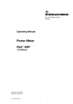
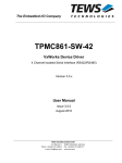
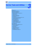
The diagram below shows how the R&S®NRP VISA Passport fits into the overall VISA
architecture. The application generally uses the VISA functions to access an
instrument. When an instrument is opened a unique resource identifier is used to
define the physical instrument link, for example, GPIB, LAN VXI-11, or USB. The R&S ®
NRP series power sensors use a proprietary binary protocol for the data transfer
between the host PC and the sensor. Therefore a driver is required on the PC side to
translate SCPI commands into the binary data required by the sensor. The so called
‘VISA Passport’ is the defined extension interface to install links between VISA and a
custom drivers and provides a way to route SCPI commands to these drivers.
APPLICATION
VISA
VISA32.dll
Passport
Interface
VISA NRP - Passport
RsViNrp.dll
NRP
NrpControl2.dll
NRP Sensor
USB
Note: Although the above picture illustrates only 32-bit modules the R&S ®NRP VISA
Passport driver is available in both 32-bit and 64-bit versions.
2
Installation
Prior to installing the R&S®NRP VISA Passport driver the following other software
packages must be installed:
1) Install the R&S® NRP-Toolkit. This package provides the USB drivers for the
NRP series power meters as well as the low level power sensor drivers.
2) Install the National Instruments VISA runtime. Currently only this VISA version
is supported.
Once the above prerequisites are met the R&S ® NRP VISA Passport can be installed.
The setup is provided as a standard installation package which will guide you through
the installation process. The name of the installation package looks like
RsViNrp_x_y_z.exe where x, y and z identify the major-, minor- and sub-version of
the current release (for example, at the time of this document being written, the current
installation package is called RsViNrp_2_5_0.exe). Depending on the architecture of
your system, either only the 32-bit version of R&S ® NRP VISA Passport
(RsViNrp.dll) or both 32-bit and 64-bit versions (RsViNrp.dll and
RsViNrp64.dll) become installed.
If the R&S® NRP VISA Passport is updated from an earlier version the old version is
removed first. In this case a reboot may be required after the installation is complete.
2.1 Message Log
The R&S® NRP VISA Passport component supports a logging mechanism for
debugging purposes. The log level is set by changing a registry key as mentioned
below. Changing can be made by following the steps listed below:
1) Start the registry editor by executing regedit on the command line.
2) Navigate to the following location:
HKEY_LOCAL_MACHINE / SOFTWARE / National Instruments /
NI-VISA / CurrentVersion / IoLibraries / RsViNrp.dll
3) Modifies the following entries as needed:
LOG_FILE
C:\RsViNrp.log
LOG_LEVEL
NONE
4) Close the registry editor tool.
The following log levels are supported:
R&S® NRP VISA Passport
DEBUG
INFO
WARN
ERROR
FATAL
NONE
Table of Contents
All messages are logged
Human readable messages, warning, and errors are logged
Warnings and errors are logged
Only error messages are logged
Only fatal errors are logged
Logging is off (default)
5
R&S® NRP VISA Passport
Table of Contents
3 Using the NRP VISA Passport
3.1 Resource Descriptor
In order to operate a device under VISA a so called VISA sessions must be opened. A
VISA session is generally opened using the viOpen function. This function requires a
resource descriptor string that clearly identifies the hardware interface as well as the
instrument used with this VISA session. The format of the resource descriptor for the
R&S® NRP series power sensors is as follows:
“RSNRP::<id>::<serial>[::INSTR]”
<id>
: USB device ID in hex. format
<serial>
: the sensor’s serial number, e.g. 100123
Please note that the hardware type is RSNRP and not USB. Using the RSNRP hardware
type instructs the VISA layer to route all further communication through the R&S ® NRP
VISA Passport driver to the corresponding power sensor(s).
3.2 VISA Functions
The R&S® NRP VISA Passport supports the following VISA functions and attributes:
viGetAttribute
VI_ATTR_RSRC_SPEC_VERSION
VI_ATTR_INTF_INST_NAME
VI_ATTR_MANF_ID
VI_ATTR_MANF_NAME
VI_ATTR_RSRC_NAME
VI_ATTR_RSRC_MANF_NAME
VI_ATTR_RSRC_MANF_ID
VI_ATTR_RSRC_IMPL_VERSION
VI_ATTR_RSRC_CLASS
VI_ATTR_TMO_VALUE (in ms)
VI_ATTR_USB_INTFC_NUM
VI_ATTR_USB_PROTOCOL
VI_ATTR_USB_SERIAL_NUM
viSetAttribute
6
R&S® NRP VISA Passport
Table of Contents
VI_ATTR_TMO_VALUE (in ms)
viEnableEvent
VI_EVENT_SERVICE_REQ
The event will be generated if the status of the NRP series power
sensor changes.
VI_EVENT_USB_INTR
This event will be generated if a power sensor gets connected
or disconnected.
VI_EVENT_EXCEPTION
This event will be generated if an error occurs.
viDisableEvent
viWrite
viRead
viAssertTrigger
viReadSTB
viClear
viOpen
viClose
viParseRsrc
viFindRsrc
7
R&S® NRP VISA Passport
Table of Contents
3.3 Return Data Format
The viRead function as well as the FETCH? query are both used to read data from the
ower sensor. Typically this data was requested by a previous SCPI command and the
result was stored in the driver cache. The format of the data returned by the two
methods therefore depends on this SCPI query. The following data types are currently
supported:
●
●
●
●
●
Binary result (unsigned char)
Integer value in ASCII format.
Floating point number in exponential ASCII format.
Multiple, comma separated floating point values in ASCII format.
Fixed length binary data block according to SCPI standard:
LC
CO
B1
B2
…
Bn
[LC]:
Number of characters in CO (length of length)
[CO]:
Data block length in bytes
[B1]:
1st byte
[B2]:
2nd byte
[Bn]:
nth byte
8
R&S® NRP VISA Passport
Table of Contents
3.4 Specific SCPI Commands
The protocol between the low level NRP power sensor drivers and the NRP series
power sensors is a proprietary binary format. As a result, the R&S ® NRP VISA passport
forwards SCPI commands to the low level drivers which translates them into binary
information that the sensor can process. In turn, all results received from the sensor
are cached by the driver and forwarded to the VISA layer as needed.
Some specific SCPI commands do not have a direct functional representation inside of
the power sensor. Instead, this functionality is mimicked by the low level NRP power
sensor driver layer:
SYSTem:ERRor?
This query returns the next error message from the driver’s error queue.
STATus:OPERation:CONDition?
This query returns the status byte from the driver’s status cache. The following table
lists which bits reflect a certain sensor state:
Bit
Function
0
0
1
0
2
0
3
0
4
sensor state is MEASURING
5
sensor state is WAIT_FOR_TRIGGER
6
0
7
0
9
R&S® NRP VISA Passport
Table of Contents
FORMat ASCii
This command sets the format of all returned numeric data to ASCII.
FORMat REAL;32
This command sets the format of all returned numeric data to floating point, 32-bit.
FETCh?
The query returns values from the driver’s internal data cache. The format depends on
the SCPI commands that were send before.
10
R&S® NRP VISA Passport
4
Table of Contents
Examples
This section provides C-code examples that may be used as a starting point for own
software projects. The code examples use the standard VISA functions, e.g.
viPrintf or viScanf to exchange data with the power sensor.
4.1 Checking for Errors
The function below repeatedly polls the driver’s error queue. The return code is false
if errors occurred or true if the queue does not contain any errors.
bool checkErrors( ViSession SensorSes )
{
bool bOK = true;
static const int BUFFER_SIZE = 4096;
char buf[BUFFER_SIZE] = {0};
memset( buf, 0, sizeof(buf) );
do
{
if( viPrintf( SensorSes, "SYST:ERR?\n" )!=0 )
return false;
if( viScanf( SensorSes, "%t", &buf )!=0 )
return false;
if( buf[0]=='0' )
break;
bOK = false;
printf( "Error: '%s'\n", buf );
} while( true );
return bOK;
}
11
R&S® NRP VISA Passport
Table of Contents
4.2 Wait for Completion
The function below polls the driver’s cache for the measurement completion state. The
function times out after about 2 seconds.
bool waitForCompletion( ViSession SensorSes )
{
int Status;
static const int BUFFER_SIZE = 4096;
char buf[BUFFER_SIZE] = {0};
printf( "\n" );
for( int i=0; i<20; i++ )
{
// sleep for 100 milliseconds
Sleep( 100 );
memset( buf, 0, sizeof(buf) );
if( viPrintf( SensorSes, "STAT:OPER:COND?\n" )!=0 )
return false;
if( viScanf( SensorSes, "%t", &buf )!=0 )
return false;
Status = atoi( buf );
printf( "." );
}
if( Status==0 )
break;
printf( "\n" );
if( Status!=0 )
return false;
return true;
}
12
R&S® NRP VISA Passport
Table of Contents
4.3 Zeroing Sensor
This example shows how to execute zero compensation on a power sensor. The
command is
CAL:ZERO:AUTO ONCE
Depending on the type of sensor zero compensation may take 4 s to 8 s (or sometimes
even longer). After executing the sensor's zero compensation an error check should
follow.
The following snippet shows an implementation in C/C++ code.
bool zeroSensor( ViSession SensorSes )
{
// This may take some sesonds...
viPrintf( SensorSes, "CAL:ZERO:AUTO ONCE\n" );
if ( !checkErrors( SensorSes ) )
{
printf( "Zeroing failed\n" );
return false;
}
}
printf( "Zeroing successful\n" );
return true;
13
R&S® NRP VISA Passport
Table of Contents
4.4 Continuous Average
The example below measures the average power of a signal. The sampling window is
set to 5 ms. Averaging is turned on with an average count of 16.
INIT:CONT OFF
SENS:FUNC "POW:AVG"
SENS:FREQ 1e9
SENS:AVER:COUN:AUTO OFF
SENS:AVER:COUN 16
SENS:AVER:STAT ON
SENS:AVER:TCON REP
SENS:POW:AVG:APER 5e-3
FORMAT ASCII
SYST:ERR?
0,”No Error”
INIT:IMM
STAT:OPER:COND?
0
FETCH?
1.001674e-002,0.000000e+000,0.000000e+000
The first set of commands configures the measurement mode as well as basic
parameters. The complete list of commands varies between sensors and can be found
in the sensor’s operating manual.
When the sensor is used in manual filter mode it is required to turn the AUTO filter off
explicitly. Otherwise the automatic filter takes precedence over the manual setting.
The FORMAT command sets the return data format to ASCII. After the configuration is
complete the sensor’s error queue should be checked for pending errors. This is done
by calling the SYST:ERR? query until the error number is zero.
The following command INIT:IMM starts the measurement. The command returns
immediately and therefore it is required to poll the measurement completion state
before fetching the result. Polling the sensor state is done with the query
STAT:OPER:COND?. A zero return value indicates that the result is available.
The following FETCH? query returns the measured power value. Since some R&S
power sensor models can be configured to also return auxiliary values (min/max or
random/max), the string returned by FETCH? contains three result values. In the
example above no auxiliary values have been configured, therefore only the first value
is used and contains the average power in Watts. (If you want to learn more about
auxiliary values, search your sensor's operating manual for command SENS:AUX.
However, bear in mind that not all sensors implement the SENS:AUX command. In
such cases the second and third value would always be 0.0)
The following C-code example demonstrates how this measurement can be
implemented.
14
R&S® NRP VISA Passport
Table of Contents
bool contav( ViSession SensorSes )
{
viPrintf( SensorSes, "INIT:CONT OFF\n"
viPrintf( SensorSes, "SENS:FUNC \"POW:AVG\"\n"
viPrintf( SensorSes, "SENS:FREQ 1e9\n"
viPrintf( SensorSes, "SENS:AVER:COUN:AUTO OFF\n"
viPrintf( SensorSes, "SENS:AVER:COUN 16\n"
viPrintf( SensorSes, "SENS:AVER:STAT ON\n"
viPrintf( SensorSes, "SENS:AVER:TCON REP\n"
viPrintf( SensorSes, "SENS:POW:AVG:APER 5e-3\n"
viPrintf( SensorSes, "FORMAT ASCII\n"
);
);
);
);
);
);
);
);
);
if( !checkErrors( SensorSes ) )
return false;
viPrintf( SensorSes, "INIT:IMM\n" );
if( !waitForCompletion( SensorSes ) )
return false;
if( viPrintf( SensorSes, "FETCH?\n" ) != 0 )
return false;
char cData[256];
memset( cData, 0, 256 );
ViUInt32 iRetCnt;
if( viBufRead( SensorSes, (ViPBuf)cData,
256, &iRetCnt ) != 0 )
return false;
// three comma seperated values
printf( "Raw Result = '%s'\n", cData );
double dResult = atof( cData );
printf( "Pav = %10.2f dBm\n",
30.0 + 10.0 * log10( fabs( dResult ) + 1e-32 ) );
}
return true;
15
R&S® NRP VISA Passport
Table of Contents
4.5 Reading Binary Data
The following function reads a block of binary data in Float32 format from the sensor.
This function can therefore be used with trace or CCDF measurements.
bool readArray( ViSession SensorSes, float *pData, int iPoints )
{
ViUInt32 iRetCnt = 0;
if( pData==0 )
return false;
if( viPrintf( SensorSes, "FETCH?\n" ) != 0 )
return false;
int iBufLen = iPoints * 4 + 32;
char *cTmpBuf = (char*)malloc( iBufLen );
if( cTmpBuf==0 )
return false;
viSetAttribute( SensorSes, VI_ATTR_TERMCHAR_EN, false );
if( viRead( SensorSes, (ViPBuf)cTmpBuf, iBufLen,
&iRetCnt ) != 0 )
{
delete cTmpBuf;
viSetAttribute( SensorSes, VI_ATTR_TERMCHAR_EN,
true );
return false;
}
viSetAttribute( SensorSes, VI_ATTR_TERMCHAR_EN, true );
if( cTmpBuf[0]!='#' )
{
delete cTmpBuf;
printf( "Unexpected prefix.\n" );
return false;
}
int iLenLen = cTmpBuf[1] - '0';
if( iLenLen<1 || iLenLen>9 )
{
delete cTmpBuf;
printf( "Invalid length of length.\n" );
return false;
}
char cLenBuf[10];
memcpy( cLenBuf, &cTmpBuf[2], iLenLen );
cLenBuf[iLenLen] = 0;
int iDataLen = atoi( cLenBuf );
if( iDataLen<=0 || iDataLen>iPoints*4 || (iDataLen%4)!=0 )
{
16
R&S® NRP VISA Passport
Table of Contents
delete cTmpBuf;
printf( "Invalid data length.\n" );
return false;
}
memcpy( pData, cTmpBuf + 2 + iLenLen, iPoints*4 );
delete cTmpBuf;
if( (int)iRetCnt < iPoints*4+2+iLenLen )
{
printf( "Insufficient number of points.\n" );
return false;
}
return true;
}
17
R&S® NRP VISA Passport
Table of Contents
4.6 Measuring Trace
The code example below demonstrates how a simple trace measurement can be
configured and how the measured data is read back to the host PC.
bool trace( ViSession SensorSes )
{
viPrintf( SensorSes, "INIT:CONT OFF\n" );
viPrintf( SensorSes, "SENS:FUNC \"XTIM:POW\"\n" );
viPrintf( SensorSes, "SENS:FREQ 1e9\n" );
viPrintf( SensorSes, "SENS:TRAC:POIN 200\n" );
viPrintf( SensorSes, "SENS:TRAC:TIME 5e-3\n" );
viPrintf( SensorSes, "SENS:TRAC:OFFS:TIME -500e-6\n" );
viPrintf( SensorSes, "TRIG:SLOP POS\n" );
viPrintf( SensorSes, "TRIG:LEV 1e-3\n" );
viPrintf( SensorSes, "TRIG:SOUR INT\n" );
viPrintf( SensorSes, "TRIG:DTIM 0\n" );
viPrintf( SensorSes, "SENS:AVER:COUN 16\n" );
viPrintf( SensorSes, "SENS:AVER:STAT ON\n" );
viPrintf( SensorSes, "SENS:AVER:TCON REP\n" );
viPrintf( SensorSes, "FORMAT REAL,32\n" );
if( !checkErrors( SensorSes ) )
return false;
viPrintf( SensorSes, "INIT:IMM\n" );
if( !waitForCompletion( SensorSes ) )
return false;
float FloatData[200];
if( !readArray( SensorSes, FloatData, 200 ) )
return false;
// simple conversion to dBm
double OutData[200];
for( int i=0; i<200; i++ )
OutData[i] = 30.0+10.0*log10(
fabs( FloatData[i] ) + 1e-32 );
// … plot data …
return true;
}
18
R&S® NRP VISA Passport
Table of Contents
4.7 Further information
As mentioned earlier, the basic driver package for R&S ® USB power sensors –the so
called R&S® NRP-Toolkit– needs to be installed before you are able to communicate
with the device(s). During the R&S® NRP-Toolkit installation you will have an option of
installing the NRP-Toolkit software development kit (SDK). When selecting this option,
the package (also) installs some VISA Passport example programs in C/C++ and C#
source-code, which show how to construct your own applications utilizing NI-VISA and
R&S® NRP VISA Passport. --- After the installation of the R&S ® NRP-Toolkit-SDK see
C:\ProgramData\Rohde-Schwarz\NRP-Toolkit-SDK\examples\Visa
for further references.
19