1
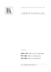
Kramer Electronics, Ltd.
USER MANUAL
Models:
PT-110, XGA Line Transmitter
WP-110, XGA Line Transmitter
PT-120, XGA Line Receiver
TP-120, XGA Line Receiver
Contents
Contents
1
2
3
3.1
3.2
3.3
3.4
3.5
3.6
3.7
4
4.1
4.2
4.3
4.4
5
5.1
5.2
6
Introduction
Getting Started
Overview
PT-110 XGA Line Transmitter
WP-110 XGA Line Transmitter
PT-120 XGA Line Receiver
TP-120 XGA Line Receiver
About the Power Connect Feature
Shielded Twisted Pair (STP) / Unshielded Twisted Pair (UTP)
Achieving the Best Performance
Your XGA Line Transmitter(s) / Receiver
Your PT-110 XGA Line Transmitter
Your WP-110 XGA Line Transmitter
Your PT-120 XGA Line Receiver
Your TP-120 XGA Line Receiver
Using the XGA Line Transmitter(s) / Receiver
Installing the WP-110 XGA Line Transmitter
Wiring the CAT 5 LINE IN / LINE OUT RJ-45 Connectors
Technical Specifications
1
1
2
2
2
3
3
3
4
4
5
5
6
7
8
10
11
12
13
Figures
Figure 1: PT-110 XGA Line Transmitter
Figure 2: WP-110 XGA Line Transmitter
Figure 3: PT-120 XGA Line Receiver
Figure 4: TP-120 XGA Line Receiver
Figure 5: TP-120 XGA Line Receiver (Underside)
Figure 6: XGA-to-Twisted Pair Transmitter and Receiver System via UTP Cable
Figure 7: CAT 5 PINOUT
5
6
7
8
9
11
12
Tables
Table 1: PT-110 Features
Table 2: WP-110 XGA Line Transmitter Features
Table 3: PT-120 XGA Line Receiver Features
Table 4: TP-120 XGA Line Receiver Features
Table 5: TP-120 XGA Line Receiver (Underside) Features
Table 6: CAT 5 PINOUT
Table 7: Technical Specifications of the PT-110 / WP-110 / PT-120 / TP-120
5
7
8
9
9
12
13
i
Introduction
1
Introduction
Welcome to Kramer Electronics! Since 1981, Kramer Electronics has been
providing a world of unique, creative, and affordable solutions to the vast
range of problems that confront the video, audio, and presentation
professional on a daily basis. In recent years, we have redesigned and
upgraded most of our line, making the best even better! Our 500-plus
different models now appear in eight groups1 that are clearly defined by
function.
Thank you for purchasing the Kramer Pico TOOLS PT-110 XGA Line
Transmitter, Kramer Wall Plate WP-110 XGA Line Transmitter, Kramer
Pico TOOLS PT-120 XGA Line Receiver, and/or Kramer TOOLS TP-120
XGA Line Receiver, which are ideal for:
Presentation and multimedia applications
Long range graphics distribution for schools, hospitals, security, and
stores
The package includes the following items:
PT-110 XGA Line Transmitter or WP-110 XGA Line Transmitter
or PT-120 XGA Line Receiver or TP-120 XGA Line Receiver
Power adapter (12V DC Input) and this user manual2
2
Getting Started
We recommend that you:
Unpack the equipment carefully and save the original box and
packaging materials for possible future shipment
Review the contents of this user manual
Use Kramer high-performance high-resolution cables3
1 GROUP 1: Distribution Amplifiers; GROUP 2: Video and Audio Switchers, Matrix Switchers and Controllers; GROUP 3:
Video, Audio, VGA/XGA Processors; GROUP 4: Interfaces and Sync Processors; GROUP 5: Twisted Pair Interfaces;
GROUP 6: Accessories and Rack Adapters; GROUP 7: Scan Converters and Scalers; and GROUP 8: Cables and Connectors
2 Download up-to-date Kramer user manuals from the Internet at this URL: http://www.kramerelectronics.com
3 The complete list of Kramer cables is on our Web site at http://www.kramerelectronics.com
1
Overview
3
Overview
This section describes:
A summary of the PT-110 XGA Line Transmitter, see section 3.1
A summary of the WP-110 XGA Line Transmitter, see section 3.2
A summary of the PT-120 XGA Line Receiver, see section 3.3
A summary of the TP-120 XGA Line Receiver, see section 3.4
The power connect feature, see section 3.5
Using shielded twisted pair (STP) / unshielded twisted pair (UTP),
see section 3.6
Recommendations for achieving the best performance, see section
3.7
3.1
PT-110 XGA Line Transmitter
Using a XGA Line Transmitter—the PT-110 or WP-110—with the PT-120
or TP-120 constitutes a VGA/XGA-to-Twisted Pair Transmitter and
Receiver.
The Kramer Pico TOOLS PT-110 is an XGA line transmitter that receives
an XGA signal and transmits it over a CAT 5 cable to the PT-120 or
TP-120 receiver. In particular, the PT-110:
Has a resolution of up to UXGA
Can use the simplest UTP CAT 5 cables, and performs even better
with higher quality cables
Has the power connect feature1
Is 12VDC fed
3.2
WP-110 XGA Line Transmitter
The Kramer Wall Plate WP-110 is an XGA line transmitter—available in
three versions: one for the USA, one for Belgium and Germany, and one for
the UK and most of Europe2—that receives an XGA signal and transmits it
over a CAT 5 cable to the PT-120 or TP-120 receiver. In particular, the
WP-110:
Has a resolution of up to UXGA
Can use the simplest UTP CAT 5 cables, however, it benefits
1 Powering via the CAT5 cable from either the receiver or the transmitter is good for 100 meters. Above it, both sides should
be fed with power
2 Excluding Belgium and Germany
2
KRAMER: SIMPLE CREATIVE TECHNOLOGY
Overview
from better quality cables
Has the power connect feature1
Is powered via a standard 12 Volt DC feed
3.3
PT-120 XGA Line Receiver
The Kramer Pico TOOLS PT-120 is an XGA line receiver that receives a
coded CAT 5 signal transmitted by either the WP-110 or the PT-110,
decodes it and converts it to an XGA output. In particular, the PT-120:
Has an operating range of more than 300 ft. (more than 100
meters) using standard CAT 5 cable and the WP-110 or the
PT-110
Includes EQ. and level controls
Has the power connect feature1
Is 12V DC fed
3.4
TP-120 XGA Line Receiver
The Kramer TOOLS TP-120 is an XGA line receiver that receives a coded
CAT 5 signal transmitted by either the WP-110 or the PT-110, decodes it
and converts it to an XGA output. In particular, the TP-120:
Has an operating range of more than 300 ft. (more than 100
meters) using standard CAT 5 cable and the WP-110 or the
PT-110
Includes EQ. and level controls
Has the power connect feature2
Is 12V DC fed
3.5
About the Power Connect Feature
The Power Connect feature applies as long as the cable can carry power. The
distance does not exceed 50 meters on standard CAT 5 cable, for longer
distances, heavy gauge cable should be used3.
For a CAT 5 cable exceeding a distance of 50 meters, separate power supplies
should be connected to the transmitter and to the receiver simultaneously.
1 Powering via the CAT5 cable from either the receiver or the transmitter is good for 60 meters. Above it, both sides should
be fed with power
2 Powering via the CAT5 cable from either the receiver or the transmitter is good for 100 meters. Above it, both sides should
be fed with power
3 CAT5 cable is still suitable for the video/audio transmission, but not for feeding the power at these distances
3
Overview
3.6
Shielded Twisted Pair (STP) / Unshielded Twisted Pair (UTP)
The decision whether to use shielded twisted pair (STP) cable or unshielded
twisted pair (UTP) cable depends on the nature of the application.
It is recommended that in applications with high interference, shielded
twisted pair (STP) cable will give better results. However, the shield itself
does create a capacitance that degrades the frequency response of the
machines. For shorter distances, of 50m or so, shielded twisted pair (STP)
cable is preferred because it provides protection from interference
(degradation is non-apparent).
For a long-range application, unshielded twisted pair (UTP) cable is
preferred. However, the unshielded twisted pair (UTP) cable should be
installed far away from electric cables, motors etc., which are prone to create
electrical interference.
It is recommended to use shielded twisted pair (STP) skew-free Kramer cable
BC-SXTP for transmitting VGA signals, and shielded twisted pair (STP)
non-skew-free Kramer BC-STP cable for digital signals.
3.7
Achieving the Best Performance
To achieve the best performance:
Use only good quality connection cables1 to avoid interference,
deterioration in signal quality due to poor matching, and elevated
noise levels (often associated with low-quality cables).
Avoid interference from neighboring electrical appliances that
may adversely influence signal quality and position your Kramer
XGA Line Transmitter(s) / Receiver away from moisture,
excessive sunlight and dust
Caution – No operator-serviceable parts inside unit.
Warning – Use only the Kramer Electronics input power
wall adapter that is provided with this unit2.
Warning – Disconnect power and unplug unit from wall
before installing or removing device or servicing unit.
1 Available from Kramer Electronics on our Web site at http://www.kramerelectronics.com
2 For example: model number AD2512C, part number 2535-000251
4
KRAMER: SIMPLE CREATIVE TECHNOLOGY
Your XGA Line Transmitter(s) / Receiver
4
Your XGA Line Transmitter(s) / Receiver
This section defines the XGA Line Transmitter(s) / Receiver:
PT-110 XGA Line Transmitter (see section 4.1)
WP-110 XGA Line Transmitter (see section 4.2)
PT-120 XGA Line Receiver (see section 4.3)
TP-120 XGA Line Receiver (see section 4.4)
4.1
Your PT-110 XGA Line Transmitter
Figure 1 and Table 1 define the PT-110:
Figure 1: PT-110 XGA Line Transmitter
Table 1: PT-110 Features
#
1
Feature
12V DC
Function
+12V DC connector for powering the unit
2
XGA INPUT
HD15F Connector
Connect to the XGA source
3
LINE OUT RJ-45
Connector
Connects to the LINE IN RJ-45
connector on the PT-120 or TP-120 XGA
1
Line Receiver
4
ON LED
Illuminates when receiving power
1 Using a UTP cable with CAT 5 connectors at both ends (the PINOUT is defined in Table 6 and Figure 7)
5
Your XGA Line Transmitter(s) / Receiver
4.2
Your WP-110 XGA Line Transmitter
The WP-110 is available in three versions: one for the US, one for Belgium
and Germany, and one for the UK and most of Europe1, as Figure 2 and
Table 2 define:
Figure 2: WP-110 XGA Line Transmitter
1 Excluding Belgium and Germany
6
KRAMER: SIMPLE CREATIVE TECHNOLOGY
Your XGA Line Transmitter(s) / Receiver
Table 2: WP-110 XGA Line Transmitter Features
#
1
Feature
XGA IN HD15F Connector
2
ON LED
3
HS Switch
4
VS3 Switch
5
6
Function
Connect to the XGA source
Illuminates when receiving power
3
1
Slide the switch to the left to change the HS polarity to (NEG.) negative
2
polarity ; slide the switch to the right (NORM.) to retain the polarity
Slide the switch to the left1 to change the VS polarity to (NEG.) negative
2
polarity ; slide the switch to the right (NORM.) to retain the polarity
LINE OUT RJ-45 Connector Connects to the LINE IN RJ-45 connector on the PT-120 or TP-120
4
XGA Line Receiver
POWER
SUPPLY
4.3
GND PIN
Connect (-) to the Ground
+12 VDC PIN
Connect (+) to the connector for powering the unit
Your PT-120 XGA Line Receiver
This section describes the PT-120 XGA Line Receiver
Figure 3 and Table 3 define the topside of the PT-120 XGA Line Receiver:
Figure 3: PT-120 XGA Line Receiver
1 By default, both switches are set to the right
2 Downgoing syncs
3 SYNC
4 Using a UTP cable with CAT 5 connectors at both ends (the PINOUT is defined in Table 8 and Figure 9)
7
Your XGA Line Transmitter(s) / Receiver
Table 3: PT-120 XGA Line Receiver Features
#
1
2
3
4
5
6
Feature
12V DC
XGA OUTPUT HD15F Connector
ON LED
LEVEL Trimmer
EQ.2 Trimmer
LINE IN RJ-45 Connector
4.4
Function
+12V DC connector for powering the unit
Connect to the XGA acceptor
Illuminates when receiving power
1
Adjusts the output signal level
2
Adjusts the cable compensation equalization level
Connects to the LINE OUT RJ-45 connector on the PT-110 or
3
WP-110 XGA Line Receiver
Your TP-120 XGA Line Receiver
This section describes the TP-120 XGA Line Receiver and its underside.
Figure 4 and Table 4 define the topside of the TP-120 XGA Line Receiver:
Figure 4: TP-120 XGA Line Receiver
1 Use a screwdriver to carefully rotate the trimmer, adjusting the appropriate level
2 Degradation and VGA/XGA signal loss can result from using long cables (due to stray capacitance), sometimes leading to a
total loss of sharpness in high-resolution signals
3 Using a UTP cable with CAT 5 connectors at both ends (the PINOUT is defined in Table 6 and Figure 7)
8
KRAMER: SIMPLE CREATIVE TECHNOLOGY
Your XGA Line Transmitter(s) / Receiver
Table 4: TP-120 XGA Line Receiver Features
#
Feature
1 12V DC
2 XGA OUT HD15F Connector
3 LINE IN RJ-45 Connector
4
5
6
ON LED
LEVEL Trimmer
3
EQ. Trimmer
Function
+12V DC connector for powering the unit
Connect to the XGA acceptor
Connects to the LINE OUT RJ-45 connector on the PT-110 or
1
WP-110 XGA Line Receiver
Illuminates when receiving power
Adjusts2 the output signal level
2
Adjusts the cable compensation equalization level
Figure 5 and Table 5 define the underside of the TP-120 XGA Line
Receiver:
Figure 5: TP-120 XGA Line Receiver (Underside)
Table 5: TP-120 XGA Line Receiver (Underside) Features
#
Feature
1 H SYNC
Switch
2 V SYNC
Switch
Function
Slide the switch up4 to change the H SYNC polarity; slide the switch down to retain
the polarity
Slide the switch up4 to change the V SYNC polarity; slide the switch down to retain
the polarity
1 Using a UTP cable with CAT 5 connectors at both ends (the PINOUT is defined in Table 6 and Figure 7)
2 Use a screwdriver to carefully rotate the trimmer, adjusting the appropriate level
3 Degradation and VGA/XGA signal loss can result from using long cables (due to stray capacitance), sometimes leading to a
total loss of sharpness in high-resolution signals
4 By default, both switches are set down for normal V SYNC and H SYNC polarity
9
Using the XGA Line Transmitter(s) / Receiver
5
Using the XGA Line Transmitter(s) / Receiver
You can use the PT-1101 XGA Line Transmitter and the TP-120 XGA Line
Receiver to configure an XGA-to-Twisted Pair Transmitter and Receiver
system.
To connect the PT-110 XGA Line Transmitter with the TP-120 XGA Line
Receiver, as the example in Figure 6 illustrates, do the following:
1. On the PT-110, connect the XGA source (for example, the HD-15 output
from a computer’s graphics card) to the XGA INPUT HD15F connector.
2. On the TP-120, connect the XGA OUT HD15F connector to the XGA
acceptor (for example, a monitor).
3. Connect the LINE OUTPUT RJ-45 connector on the PT-110 to the LINE
IN RJ-45 connector on the TP-120, via UTP cabling (with a range of more
than 300ft (>100m)).
4. On both2 the PT-110 and the TP-120, connect the 12V DC power adapter
to the power socket and connect the adapter to the mains electricity.
The signal from the XGA source is transmitted via CAT 5 cable, decoded
and converted at the XGA OUT HD15F connector to the XGA acceptor.
5. On the TP-120, adjust3 the output signal level and/or cable compensation
equalization level, if required.
6. If necessary, set the H SYNC and V SYNC switches4, on the undersides of
the units.
1 You can use the WP-110 (not shown in Figure 6) instead of the PT-110. For details, see section 5.1
2 For distances of up to 100 meters you can connect a power adapter to either the PT-110 or TP-120. Above it, both sides
should be fed with power
3 Use a screwdriver to carefully rotate the trimmer, adjusting the appropriate level
4 By default, both switches are set for normal H SYNC and V SYNC polarity
10
KRAMER: SIMPLE CREATIVE TECHNOLOGY
Using the XGA Line Transmitter(s) / Receiver
Figure 6: XGA-to-Twisted Pair Transmitter and Receiver System via UTP Cable
5.1
Installing the WP-110 XGA Line Transmitter
To install your WP-110 XGA Line Transmitter:
1. Connect the LINE OUT RJ-45 connector to the pre-installed UTP wiring
in the wall box opening that connects via UTP cabling to the LINE IN
RJ-45 connector of the PT-120 or TP-120.
2. Connect your 12V DC power supply to the POWER SUPPLY pins1, taking
care that polarity is correct.
3. Insert the WP-110 directly into the wall box opening, and then mount the
front panel securely using the screws.
4. Connect the XGA source to the XGA IN HD15F connector.
1 Connect the wire labeled “+” to the +12V pin, and the wire labeled “–” to the GND pin
11
Using the XGA Line Transmitter(s) / Receiver
5.2
Wiring the CAT 5 LINE IN / LINE OUT RJ-45 Connectors
Table 6 and Figure 7 define the CAT 5 PINOUT, using a straight pin to pin
cable with RJ-45 connectors:
Table 6: CAT 5 PINOUT
EIA /TIA 568A
PIN
1
2
3
4
5
6
7
8
Wire Color
Green / White
Green
Orange / White
Blue
Blue / White
Orange
Brown / White
Brown
EIA /TIA 568B
PIN
1
2
3
4
5
6
7
8
Wire Color
Orange / White
Orange
Green / White
Blue
Blue / White
Green
Brown / White
Brown
Pair 1
4 and 5
Pair 1
Pair 2
3 and 6
Pair 2
1 and 2
Pair 3
1 and 2
Pair 3
3 and 6
Pair 4
7 and 8
Pair 4
7 and 8
12
Figure 7: CAT 5 PINOUT
4 and 5
KRAMER: SIMPLE CREATIVE TECHNOLOGY
Technical Specifications
6
Technical Specifications
Table 7 lists the technical specifications:
1
Table 7: Technical Specifications of the PT-110 / WP-110 / PT-120 / TP-120
INPUTS:
OUTPUTS:
MAX. OUTPUT
LEVEL:
RESOLUTION:
2
DIFF. GAIN :
2
DIFF. PHASE
2
K-FACTOR :
2
S/N RATIO :
CONTROLS:
PT-110
1 VGA / UXGA on
an HD15 connector
1 RJ-45 LINE
OUTPUT connector
WP-110
1 VGA / UXGA on an HD15
connector
1 RJ-45 LINE OUT
connector
PT-120
1 RJ-45 LINE IN
connector
1 VGA / UXGA on an
HD15 connector
1.5Vpp
TP-120
1 RJ-45 LINE IN
connector
1 VGA / UXGA on an
HD15 connector
1.4Vpp
Up to UXGA
2.9% (worst case)
0.3 Deg (worst case)
<0.05%
69dB (worst case)
–7.7dB to +3.1dB,
130m level,
0dB to +25dB
EQ. @ 50MHz
COUPLING:
AC
AC
DC
POWERSOURCE: 12 VDC 60mA
12 VDC 60mA
12 VDC 175mA
DIMENSIONS:
6cm x 6.5cm x 2.5cm USA: 6.9cm x 3.8cm x 11.4cm 6cm x 6.5cm x 2.5cm
(2.36" x 2.56" x 1",
(2.36" x 2.56" x 1",
(2.72" x 1.5" x 4.5", W, D, H)
W, D, H)
W, D, H)
Belgium and Germany:
8cm x 3.8cm x 8cm
(3.15" x 1.5" x 3.15", W, D, H)
–7.5dB to +4.4dB,
130m level, 0dB to
+33dBm 130m,
EQ. @ 50MHz
AC
12 VDC 160mA
12cm x 7.5cm x 2.5cm
(4.7" x 0.98" x 2.95",
W, D, H)
3
WEIGHT:
UK and most of Europe :
8.6cm x 3.8cm x 8.6cm
(3.39" x 1.5" x 3.39", W, D, H)
0.14 kg. (0.31 lbs.) approx.
0.14 kg. (0.31 lbs.)
approx.
ACCESSORIES: Power supply
OPTIONS:
19-inch rack adapters
0.14 kg. (0.31 lbs.)
approx.
0.3kg. (0.66lbs.)
approx.
1 Specifications are subject to change without notice
2 For the Transmitter/Receiver pair
3 Excluding Belgium and Germany
13
14
KRAMER: SIMPLE CREATIVE TECHNOLOGY
For the latest information on our products and a list of Kramer
distributors, visit our Web site: www.kramerelectronics.com
where updates to this user manual may be found.
We welcome your questions, comments and feedback.
Safety Warning:
Disconnect the unit from the power supply before
opening/servicing.
Caution
Kramer Electronics, Ltd.
Web site: www.kramerelectronics.com
E-mail: [email protected]
P/N: 2900-000085 REV 6