1
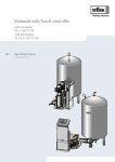
Variomat 1
GB
Operating manual
Original operating manual
2014-03-12
Contents
English
Variomat1
2014-03-12
Contents
1
Notes on the operating manual.....................................................................................................................................................5
2
Liability and guarantee...................................................................................................................................................................5
3
Safety................................................................................................................................................................................................6
3.1
3.2
3.3
3.4
3.5
3.6
4
Explanation of symbols........................................................................................................................................................................ 6
3.1.1
Symbols and notes used................................................................................................................................................... 6
3.1.2
Safety symbols used.......................................................................................................................................................... 6
Personnel requirements ...................................................................................................................................................................... 7
Personal protective equipment .......................................................................................................................................................... 7
Intended use.......................................................................................................................................................................................... 7
Inadmissible operating conditions..................................................................................................................................................... 7
Residual risks ......................................................................................................................................................................................... 8
Description of the device................................................................................................................................................................9
4.1
4.2
4.3
4.4
4.5
4.6
Description............................................................................................................................................................................................. 9
Overview ................................................................................................................................................................................................ 9
Identification .......................................................................................................................................................................................10
4.3.1
Nameplate ........................................................................................................................................................................10
4.3.2
Type code..........................................................................................................................................................................10
Function ...............................................................................................................................................................................................11
Scope of delivery.................................................................................................................................................................................13
Optional equipment and accessories ..............................................................................................................................................13
5
Technical data ...............................................................................................................................................................................14
6
Installation.....................................................................................................................................................................................15
6.1
6.2
6.3
6.4
6.5
6.6
7
Installation conditions .......................................................................................................................................................................16
6.1.1
Incoming inspection .......................................................................................................................................................16
Preparatory work ................................................................................................................................................................................16
Execution..............................................................................................................................................................................................17
6.3.1
Positioning........................................................................................................................................................................17
6.3.2
Installation of add-on components for the tanks.......................................................................................................18
6.3.3
Tank installation ..............................................................................................................................................................19
6.3.4
Hydraulic connection......................................................................................................................................................21
6.3.5
Fitting the thermal insulation........................................................................................................................................24
6.3.6
Fitting the level sensor ...................................................................................................................................................25
Switching and make-up variants......................................................................................................................................................26
Electrical connection ..........................................................................................................................................................................29
6.5.1
Terminal diagram ............................................................................................................................................................30
6.5.2
RS-485 interface...............................................................................................................................................................32
Installation and commissioning certificate.....................................................................................................................................33
Commissioning..............................................................................................................................................................................34
7.1
7.2
7.3
7.4
7.5
7.6
7.7
Checking the requirements for commissioning.............................................................................................................................34
Determine the P0 minimum operating pressure for the controller............................................................................................35
Controller .............................................................................................................................................................................................36
7.3.1
Operator panel.................................................................................................................................................................36
Modifying the controller's start routine ..........................................................................................................................................37
Filling the tanks with water...............................................................................................................................................................39
7.5.1
Filling with a hose ...........................................................................................................................................................39
7.5.2
Filling with the make-up solenoid valve......................................................................................................................39
Venting the pump...............................................................................................................................................................................40
Parametrising the controller in the Customer menu ....................................................................................................................41
Variomat 1 — 2014-03-12
English — 3
Contents
7.8
8
Operation...................................................................................................................................................................................... 47
8.1
8.2
9
Starting Automatic mode.................................................................................................................................................................. 46
Operating modes ................................................................................................................................................................................ 47
8.1.1
Automatic mode.............................................................................................................................................................. 47
8.1.2
Manual mode ................................................................................................................................................................... 48
8.1.3
Stop mode ........................................................................................................................................................................ 48
8.1.4
Summer operation .......................................................................................................................................................... 49
8.1.5
Restarting ......................................................................................................................................................................... 49
Controller ............................................................................................................................................................................................. 50
8.2.1
Customer menu ............................................................................................................................................................... 50
8.2.2
Service menu.................................................................................................................................................................... 50
8.2.3
Default settings ............................................................................................................................................................... 51
8.2.4
Messages .......................................................................................................................................................................... 53
Maintenance................................................................................................................................................................................. 56
9.1
9.2
9.3
9.4
9.5
Maintenance schedule....................................................................................................................................................................... 57
Cleaning ............................................................................................................................................................................................... 58
9.2.1
Cleaning the dirt trap...................................................................................................................................................... 58
9.2.2
Cleaning the tanks........................................................................................................................................................... 59
Checking switching points ................................................................................................................................................................ 60
Maintenance certificate ..................................................................................................................................................................... 61
Inspection ............................................................................................................................................................................................ 62
9.5.1
Pressure-bearing components ...................................................................................................................................... 62
9.5.2
Inspection prior to commissioning............................................................................................................................... 62
9.5.3
Inspection intervals......................................................................................................................................................... 62
10
Disassembly.................................................................................................................................................................................. 63
11
Annex ............................................................................................................................................................................................ 64
11.1
11.2
11.3
11.4
11.5
4 — English
Reflex Customer Service .................................................................................................................................................................... 64
Conformity and standards................................................................................................................................................................. 65
Certificate No. of the design type examination ............................................................................................................................. 67
Guarantee ............................................................................................................................................................................................ 67
Glossary ................................................................................................................................................................................................ 67
Variomat 1 — 2014-03-12
Notes on the operating manual
1
Notes on the operating manual
This operating manual is an important aid for the safe and reliable function of the device.
The operating manual is intended to:
• Avert dangers to personnel.
• Understand the device.
• Obtain optimal functioning.
• Early identify and rectify problems.
• Avoid faults caused by improper use.
• Prevent repair costs and downtimes.
• Increase reliability and service life.
• Prevent damage to the environment.
Reflex Winkelmann GmbH cannot accept any liability for damage caused by ignoring this operating manual. In addition to this operating
manual, you must comply with national legislation and regulations in the country of use (accident prevention, environment protection,
save and proper work, etc.).
This operating manual describes the device with basic equipment for degassing and interfaces for optional equipment with additional
functions. For optional equipment and accessories, see chapter 4.6 "Optional equipment and accessories" on page 13 .
Notice!
Every person installing this equipment or performing any other work at the equipment is required to carefully read this
operating manual prior to commencing work and to comply with its instructions. The manual is to be provided to the
product operator and must be stored near the product for access at any time.
2
Liability and guarantee
The product is manufactured to the latest engineering standards and acknowledged safety regulations. Nevertheless, risk of injury and
death for the user and other parties and damage to the system and other property can arise from its use.
Modifications of the device such as changes of the hydraulic system or interference with the interconnection are strictly prohibited.
The liability and guarantee of the manufacturer are excluded when the malfunction can be traced back to one or more of the following
causes:
• Improper use of the device.
• Improper commissioning, operation, maintenance, servicing, repair, and installation of the device.
• Ignoring the safety notes in this operating manual.
• Device operation with defective or improperly installed safety and/or protective equipment.
• Failure to perform maintenance and inspection work at due times.
• Use of unauthorised replacement parts and accessories.
The precondition for any guarantee claims is the proper installation and commissioning of the device.
Notice!
Have the Reflex Customer Service carry out commissioning and the annual maintenance, see chapter 11.1 "Reflex
Customer Service" on page 64 .
Variomat 1 — 2014-03-12
English — 5
Safety
3
Safety
3.1
Explanation of symbols
3.1.1
Symbols and notes used
The following symbols are used in this operating manual.
Danger
•
Danger to life and/or severe damage to health
– The corresponding warning symbol in combination with the "Danger" signal term indicates an imminent
threatening danger which will result in death or severe (irreversible) injuries.
Warning
•
Severe damage to health
– The corresponding warning symbol in combination with the "Warning" signal term indicates a threatening
danger which may result in death or severe (irreversible) injuries.
Caution
•
Damage to health
– The corresponding warning symbol in combination with the "Caution" signal term indicates a danger which
may result in minor (reversible) injuries.
Attention!
•
Damage to property
– This symbol in combination with the "Attention" signal word indicates a situation that may cause damage to
the product itself or objects in its vicinity.
Notice!
This symbol in combination with the "Notice" signal word indicates useful tips and recommendations regarding the
efficient use of the product.
3.1.2
Safety symbols used
The following safety symbols are used in this operating manual. They are also attached to the equipment or in its vicinity.
This symbol warns of electric.voltage.
This symbol warns of a hot surface.
This symbol warns of overpressure in conduits and connections.
6 — English
Variomat 1 — 2014-03-12
Safety
3.2
Personnel requirements
Only specialist personnel or specifically trained personnel may install and operate the equipment.
The electric connections and the wiring of the device must be executed by a specialist in accordance with all applicable national and
local regulations.
3.3
Personal protective equipment
When working at the system, wear the stipulated personal equipment such as hearing and eye protection, safety boots, helmet,
protective clothing, protective gloves.
See the national regulation of your country for personal protective equipment required.
3.4
•
•
3.5
Intended use
The devices are manufactured from steel with exterior coating; the interior is uncoated. The devices may be used only in systems
that are sealed against corrosion and with the following water types:
• Non-corrosive
• Chemically non-aggressive
• Non-toxic
The ingress of atmospheric oxygen by permeation into the entire heating and cooling water system, make-up water and similar
must be reliably minimised during operation.
Inadmissible operating conditions
The devices are not suited for the following conditions.
• In mobile system operation
• For outdoors operation
• For the use with mineral oils
• For the use with flammable media
• For the use with distilled water
Notice!
Changes to the hydraulic system or interference with the interconnection are strictly prohibited.
Variomat 1 — 2014-03-12
English — 7
Safety
3.6
Residual risks
This device has been manufactured to the current state of the art. However, some residual risk cannot be excluded.
Caution – risk of burning!
•
Excessive surface temperatures in heating systems can cause skin to burn.
– Wait until surfaces have cooled down or wear protective gloves.
– The operator is required to attach corresponding warning notes in the device vicinity.
Caution – risk of injury!
•
Incorrect installation or service work may cause burns and other injuries at the connections when hot water or
steam suddenly escape at pressure.
– Ensure proper installation.
– Ensure that the system is de-pressurised before performing service work at the connections.
Warning – large weight!
•
8 — English
The devices are very heavy. Thus, there is a risk of physical damage and accidents.
– Use only lifting gear suitable for transport and installation.
Variomat 1 — 2014-03-12
Description of the device
4
Description of the device
4.1
Description
The Variomat is a pump-controlled pressure maintaining, make-up and degassing station for heating and cooling water systems. The
Variomat is essentially a controller with pump and at least one expansion tank. A diaphragm in the extension tank separates the same
into an air and a water space, preventing the penetration of atmospheric oxygen into the expansion water.
The Variomat provides the following safety features:
• Optimisation of all pressure maintaining, degassing and make-up processes.
• No direct intake of air thanks to a regulation of the pressure maintenance with automatic make-up.
• No circulation issues caused by free bubbles in the circuit water.
• Reduced corrosion damage due to oxygen removal from fill and make-up water.
4.2
Overview
1
"VE" aeration and de-aeration
6
"PU" pump
2
"DV" degassing valve
7
"FD" feed and drain cock
3
"PIS" pressure transducer
8
"LIS" level sensor
4
"PV" overflow valve
WC Make-up connection
5
"WV" make-up valve
EC
Degassing connection
• Gas-rich water inlet
• Degassed water outlet
Variomat 1 — 2014-03-12
English — 9
Description of the device
4.3
Identification
4.3.1
Nameplate
The nameplate provides manufacturer information, year of manufacture, serial number, and technical data.
Information on nameplate
Type
Serial No.
min. / max. allowable pressure P
Meaning
Device name
Serial number
Minimum/maximum
permissible pressure
max. continuous operating
Maximum temperature for
temperature
continuous operation
min. / max. allowable
Minimum/maximum
temperature / flow temperature permissible
TS
temperature/TS flow
temperature
Year built
Year of manufacture
min. operating pressure set up on Factory-set minimum
shop floor
operating pressure
at site
Set minimum operating
pressure
max. pressure saftey valve
Factory-set opening
factory - aline
pressure of the safety valve
at site
Set opening pressure of the
safety valve
4.3.2
Type code
No.
1
Control unit with number of pumps "1"
2
Primary tank with 500 litre volume
3
Secondary tank with 500 litre volume
10 — English
Type code
Variomat VS 1, VG 500 l, VF 500 l
1
2
3
Variomat 1 — 2014-03-12
Description of the device
4.4
1
2
3
Function
WV
PIS
PV
Make-up valve
Pressure sensor
Overflow limiter (motor ball valve)
PU
SV
Pump (pressure maintenance)
Safety valve
6
Heating system
"MAG" pressure expansion tank
Reflex Fillset Impulse, see chapter 4.6 "Optional
equipment and accessories" on page 13 .
Control unit
Hydraulic inlets
• For gas-rich water
• For degassed water
Air space, "VG" primary tank
EC
7
ST
FQIRA+
WC
Air space, "VG" secondary tank
Dirt trap
Contact water meter
Make-up line
FD
LIS
DV
VE
Expansion line
• For gas-rich water
• For degassed water
Feed and drain cock
Pressure pick-up
Degassing valve
Aeration and de-aeration
4
5
The device is a pressure maintaining station for heating and cooling water systems. It is used for maintaining pressure, making-up and
degassing the water in heating and cooling systems. It comprises a control unit consisting of a controller with hydraulics and at least
one expansion tank.
Expansion tank
One "VG" primary tank and multiple optional "VF" secondary tanks may be connected. A diaphragm separates the tanks into an air and a
water space, preventing the penetration of atmospheric oxygen into the expansion water. The "VE" line connects the air space with the
atmosphere. The "VG" primary tank is hydraulically flexibly connected to the control unit. The function of the "LIS" level measuring using
a pressure pick-up is thus ensured.
Control unit
The control unit contains the hydraulic system and the controller. The "PIS" pressure transducer records the pressure and the "LIS"
pressure pick-up registers the level; both values are displayed at the controller.
Variomat 1 — 2014-03-12
English — 11
Description of the device
Maintaining pressure
The pressure in the system rises when the water is heated. When the pressure set at the controller is exceeded, the "PV" overflow valve
opens and drains water from the system into the "VG" primary tank, using the "EC" expansion line. The pressure within the system drops.
The pressure in the system drops when the water cools. When the pressure drops below the set value, the "PU" pump is activated and
uses the "EC" expansion line to transport water from the "VG" primary tank back into the system. The pressure in the system rises. The
controller ensures that the pressure is maintained, further supported by the stabilisation provided by the "MAG" expansion tank.
Degassing
Two "EC" expansion lines are required to degas the system water. One line is intended for gas-rich water from the system, and the other
one serves to return the degassed water to the system. During the degassing action, the "PU" pump and the "PV" overflow valve are in
operation. This transports a gas-rich partial flow of the system water V through the de-pressurised "VG" primary tank. Atmospheric
pressure is used to separate the free and dissolved gases and to discharge them through the "DV" degassing valve. The controller
ensures the hydraulic equalisation by regulating the stroke of a motor ball valve used as the "PV" overflow valve. There are three
different modes for this process: continuous, interval or run-on degassing.
Make-up
When the water level in the "VG" primary tank falls below the minimum, the "WV" make-up valve opens until the set level is again
reached. During the make-up process, the number of requests, the time and the make-up duration within a cycle are monitored. Using a
FQIRA+ contact water meter, the system monitors each individual make-up volume and the overall make-up volume.
12 — English
Variomat 1 — 2014-03-12
Description of the device
4.5
Scope of delivery
The scope of delivery is described in the shipping document and the content is shown on the packaging. Immediately after receipt of the
goods, please check the shipment for completeness and damage. Please notify us immediately of any transport damage.
Basic pressure-maintaining equipment:
• The device on a pallet.
– Control unit and "VG" primary tank.
– Connection kit in cardboard box and add-on components in a plastic bag for the "VG" primary tank.
– Plastic sleeve with operating manual.
Optional equipment and accessories:
• Thermal insulation for the "VG" primary tank.
• "VF" secondary tanks with add-on components in a plastic bag and a set of flexible hoses.
4.6
Optional equipment and accessories
The following optional equipment and accessories are available for this device:
• Fillset for make-up with water.
– Fillset with integrated back flow preventer, water meter, dirt trap, and locking mechanisms for the "WC" make-up line.
• Fillset Impulse with FQIRA+ contact water meter for make-up with water.
• Servitec for make-up and degassing.
• Fillsoft for softening the make-up water from the public water network.
– Fillsoft is installed between Fillset and the device. The device controller evaluates the make-up quantities and signals a
required replacement of the softening cartridges.
• Enhancements for the device controller:
– I/O module for standard communication.
– Master-Slave-Connect for master controllers for maximum 10 devices.
– Bus modules:
• Lonworks Digital
• Lonworks
• Profibus DP
• Ethernet
• Diaphragm rupture monitor.
Notice!
Separate operating instructions are supplied with accessories.
Variomat 1 — 2014-03-12
English — 13
Technical data
5
Technical data
Control unit
Type
Part No.
Electric output
Voltage
Frequency
Power Supply
Width
Height
Depth
Weight
VS 1
8910100
0.75 kW
230 V
50 Hz
Plug
530 mm
680 mm
580 mm
25 kg
Mechanical connection in
inches
2 x G1
Tanks
Type
"VG" primary tank, Article No.
"VF" secondary tank, Article No.
"VW" thermal insulation for
heating systems, Article No.
Diameter Ø "D"
Height "H"
Height "h"
Weight
Connection in inch
200
8600011
8610000
300
8600111
8610100
400
8600211
8610200
500
8600311
8610300
600
8600411
8610400
800
8600511
8610500
1000
8600611
8610600
7985700
7986000
7995600
7983900
7995700
7993800
7993900
Type
"VG" primary tank, Article No.
"VF" secondary tank, Article No.
"VW" thermal insulation for
heating systems, Article No.
Diameter Ø "D"
Height "H"
Height "h"
Weight
Connection in inch
1000
8600705
8610705
1500
8600905
8610905
2000
8601005
8611005
3000
8601205
8611205
4000
8601305
8611305
5000
8601405
8611405
7986800
7987000
7987100
7993200
7993300
7993400
14 — English
634 mm
1060 mm
146 mm
37 kg
G1
1000 mm
2130 mm
350 mm
320 kg
G1
634 mm
1360 mm
146 mm
54 kg
G1
1200 mm
2130 mm
350 mm
465 kg
G1
740 mm
1345 mm
133 mm
65 kg
G1
740 mm
1560 mm
133 mm
78 kg
G1
1200 mm
2590 mm
350 mm
565 kg
G1
Variomat 1 — 2014-03-12
1500 mm
2590 mm
380 mm
795 kg
G1
740 mm
1810 mm
133 mm
94 kg
G1
1500 mm
3160 mm
380 mm
1080 kg
G1
740 mm
2275 mm
133 mm
149 kg
G1
1500 mm
3695 mm
380 mm
1115 kg
G1
740 mm
2685 mm
133 mm
156 kg
G1
Installation
6
Installation
Danger – Electric shock!
•
Serious injury or death due to electric shock.
– Any system in which the device is to be installed must be de-energised.
– Ensure that the system is locked and cannot be switched on by other personnel.
– Installation work for the electric connection of the device must be carried out by an authorised electrician in
compliance with electrical engineering regulations.
Caution – risk of injury!
•
Incorrect installation or service work may cause burns and other injuries at the connections when hot water or
steam suddenly escape at pressure.
– Ensure proper installation.
– Ensure that the system is de-pressurised before performing service work at the connections.
Caution – risk of burning!
•
Excessive surface temperatures in heating systems can cause skin to burn.
– Wait until surfaces have cooled down or wear protective gloves.
– The operator is required to attach corresponding warning notes in the device vicinity.
Caution – Risk of injury due to falls or bumps!
•
Bruising from falls or bumps at system components during installation.
– Wear personal protective equipment (helmet, protective clothing, gloves, safety boots).
Notice!
•
The proper installation and commissioning must be confirmed in the installation, commissioning and maintenance
certificate. This certificate is prerequisite for any warranty claim.
– Have the Reflex Customer Service carry out commissioning and the annual maintenance.
Variomat 1 — 2014-03-12
English — 15
Installation
6.1
Installation conditions
6.1.1
Incoming inspection
Prior to shipping, this device was carefully inspected and packed. Damages during transport cannot be excluded.
Notice!
After receipt of the goods, please check the shipment for completeness and damage. Document any transport damage.
Contact the shipper to register a claim for damage.
6.2
Preparatory work
Conditions for the device installation:
• No access by unauthorised personnel.
• Frost-free, well ventilated room.
– Room temperature 0 °C to 45 °C.
• Level, stable flooring.
– Ensure sufficient bearing strength of the flooring before filling the "VG" and "VF" tanks.
– Ensure that the control unit and the "VG" and "VF" tanks are installed on the same level.
• Filling and dewatering option.
– Provide a DN 15 filling connection according to DIN 1988 T 4.
– Provide an optional cold water inlet.
– Prepare a drain for the drain water.
• Electric connection: 230 V~, 50 Hz, 16 A with upstream ELCB: Tripping current 0.03 A.
• Use only approved transport and lifting gear.
– The load fastening points at the "VG" and "VF" tanks must be used only as installation resources.
16 — English
Variomat 1 — 2014-03-12
Installation
6.3
Execution
Attention! – Damage caused by improper installation
•
Remember that the connection of pipelines or equipment originating with the system may cause additional stresses
to the device.
– Ensure a stress-free installation of the pipe connections between the device and the overall system.
For installation, proceed as follows:
• Position the device.
• Complete the "VG" primary tank and the optional "VF" secondary tanks.
• Create the water-side connections of the control unit to the system.
• Create the interfaces according to the terminal plan.
• Connect the water connection optional "VF" secondary tanks to each other and to the "VG" primary tank.
Notice!
For installation, note the operability of the valves and the inlet options of the connecting lines.
6.3.1
Positioning
Determine the positions for the control unit and the "VG" and
"VF" tanks (if used).
– The control unit can be installed on either side or in front
of the "VG" primary tank. The distance of the control unit
to the primary tank results from the connection set
supplied.
Variomat 1 — 2014-03-12
English — 17
Installation
6.3.2
Installation of add-on components for the tanks
The add-on components are packed in plastic bags and
attached to the base of the devices.
• For "VG" and "VF" tanks up to 740 mm Ø.
– "DV" degassing valve and reducing sleeve
Rp 1/2 × Rp ⅜.
– "VE" equalisation elbow.
• For "VG" and "VF" tanks up to 1000 mm Ø.
– "DV" degassing valve and reducing sleeve Rp 1
× Rp ⅜.
– "VE" equalisation elbow.
For add-on components, proceed as follows:
1. Seal the "DV" degassing valve and the reducing
sleeve and assemble.
2. Install the assembly at the connection of the
corresponding tank.
3. Remove the protective cap from the "DV"
degassing valve.
4. Use the clamping ring screw connection to install
the "VE" equalisation elbow for aeration and deaeration at the tanks.
1 "VE" equalisation
elbow
18 — English
Variomat 1 — 2014-03-12
2 "DV" degassing valve with reducing sleeve
Installation
6.3.3
Tank installation
Attention! – Damage caused by improper installation
•
Remember that the connection of pipelines or equipment originating with the system may cause additional stresses
to the device.
– Ensure a stress-free installation of the pipe connections between the device and the overall system.
Attention! – Equipment damage
•
The pump will be damaged if it is permitted to run dry.
– Ensure that the connections for the overflow collector and the pump are not interchanged.
– Ensure the correct connection of the pump to the primary tank.
Comply with the following notes regarding the installation of
the "VG" primary tank and the "VF" secondary tanks:
•
•
•
•
•
•
All flange openings at the tanks are viewing and
maintenance openings. Install the "VG" primary tank and
the "VF" secondary tanks, if provided, with sufficient
spaces at the sides and the top.
Install the "VG" and "VF" tanks on a level plane.
Ensure rectangular and free-standing position of the
tanks.
If you use "VF" secondary tanks in addition to the
"VG"primary tank, ensure that all tanks have the same
type and dimensions.
Do not attach the tanks to the flooring to ensure the
functioning of the "LIS" level sensor.
Install the control unit on the same level as the tanks.
Variomat 1 — 2014-03-12
English — 19
Installation
•
•
Align the "VG" primary tank.
– The adhesive label (1) and the connections must
point to the connection points at the control unit.
– The distance of the primary tank to the control unit
must match the length of the connection set.
Connect the connection set (2) and (3) with the screw
fittings and gaskets to the connections at the lower tank
flange of the "VG" primary tank.
– For tanks up to 740 mm Ø:
• Connect the connection set (2) and (3) to the
two free 1-inch barrel nipples at the tank
flange.
• Connect the connection set (4) of the secondary
tank to the T-joint at the outlet of the tank
flange.
– For tanks from 1000 mm Ø:
• Connect the connection set (2) to the 1-inch
barrel nipple of the tank flange.
• Connect the connection sets (3) and (4) to the
T-joint at the 1-inch barrel nipple of the tank
flange.
1 Adhesive label
2 "Overflow collector" connection
set
3 "Pump" connection set
4 "VF" secondary tank
connection set
Notice!
If necessary, install the supplied connection set (4) at the "VF" secondary tank. Connect the connection set (4) with a usersupplied pipeline to the "VF" primary tank.
20 — English
Variomat 1 — 2014-03-12
Installation
6.3.4
Hydraulic connection
6.3.4.1
Connection to the facility system
Caution – risk of burning!
•
Hot water vapour can cause burns to skin and eyes.
– Install the blow-off line from the control unit's safety valve so that a hazard to persons in the vicinity is
excluded.
Attention! – Damage caused by improper installation
•
Remember that the connection of pipelines or equipment originating with the system may cause additional stresses
to the device.
– Ensure a stress-free installation of the pipe connections between the device and the overall system.
Connection to the "VG" primary tank
The control unit is positioned to the "VG" primary tank as determined by the selected installation variant, and is connected to the tank
using its connection set, see chapter 6.3.3 "Tank installation" on page 19 .
The connections to the system are identified by adhesive labels on the control unit:
Pumpen
Zur Anlage
Überströmung
Zur Anlage
Pump to system connection
Overflow valve to system
connection
Variomat 1 — 2014-03-12
Nachspeisung
Zum Behälter
Make-up to system connection
English — 21
Installation
Connection to the system
1
2
Heat generator
For optional equipment and accessories, see chapter 4.6
"Optional equipment and accessories" on page 13 .
3
4
5
6
"VF" secondary tank
Reflex rapid-action coupling R 1 x 1
"VG" primary tank
Connection set, "VG" primary tank
7
EC
Control unit
Degassing line
• Gas-rich water from the system
• Degassed water to the system
LIS "LIS" level sensor
WC Make-up line
MAG Pressure expansion tank
If required, install a diaphragm expansion tank MAG ≥ 35 litres (Reflex N, for example). It reduces the switching frequency and can be
also used in the individual protection of the heat generators. According to DIN / EN 12828, the installation of valves between the device
and the heat generator is required for heating systems. Otherwise, protected shut-off devices must be installed.
Notice!
Due to the optimal degassing capacity of the device, we recommend the installation of a diaphragm expansion tank MAG
≥ 35 litre (Reflex N, for example).
22 — English
Variomat 1 — 2014-03-12
Installation
"EC" expansion lines
Because of the degassing function, you must install two "EC"
expansion lines.
• One line from the system for the gas-rich water.
• One line to the system for the degassed water.
The "DN" nominal connection diameter for the "EC"
expansion lines must be designed for the "P0" minimum
operating pressure.
DN25:
P0 ≥ 2,0 bar
DN32:
P0 = 0,5 bar – 2,0 bar
see chapter 7.2 "Determine the P0 minimum operating
pressure for the controller" on page 35 .
The "DN" nominal connection diameter applies to an
expansion line length of up to 10 metres. Beyond this length,
select the next larger dimension. Integrate with the "V" main
flow volume of the system. Viewed in system flow direction,
you must integrate the gas-rich expansion line upstream of
the expansion line transporting the degassed water.
Ensure that particulate dirt cannot enter and thus creating an
overload of the "ST" dirt trap. Connect the "EC" expansion
lines according to the following installation variants.
Notice!
The water temperature at the connection point of the "EC" expansion lines must be in the range of 0 °C to 70 °C. The use
of in-line tanks does not increase the application range. Because the thermal protection is not ensured due to the flow
during the degassing phase.
Variomat 1 — 2014-03-12
English — 23
Installation
6.3.4.2
Make-up line
"WC" make-up line
See Chapter "Switching and make-up variants" for the various make-up variants, see chapter 6.4 "Switching and make-up variants" on
page 26 . If you don't connect the automatic water make-up to the device, you must close the connection of the "WC" make-up line with
a R ½ " blind plug. Prevent a potential device fault by ensuring manual water make-up. Install at least one "ST" dirt trap with a mesh size
≤ 0.25 mm close upstream to the make-up solenoid valve. Install a short line between the "ST" dirt trap and the solenoid valve.
Notice!
Use a pressure reducer in the "WC" make-up line if the idle pressure exceeds 6 bar.
6.3.5
Fitting the thermal insulation
Install the "VW" thermal insulation (2) around the "VG" primary tank (1) and close the
insulation with the zip fastener.
Notice!
For heating systems, insulate the "VG" primary tank and the "EC" expansion lines against heat loss. The cover of the
primary tank does not require insulation, as there is space between the diaphragm and the tank wall. The "VF" secondary
tanks do not require insulation either.
Notice!
Condensate formation requires insulation by the user.
24 — English
Variomat 1 — 2014-03-12
Installation
6.3.6
Fitting the level sensor
Attention! – Equipment damage
•
Incorrect installation may result in damages to the "LIS" level sensor, malfunctioning and incorrect measurements
from the pressure pick-up.
– Comply with the instructions regarding the installation of the pressure pick-up.
The "LIS" level sensor uses a pressure pick-up. This pressure pick-up is to be installed after the "VG" primary tank has been placed at its
final position, see chapter 6.3.3 "Tank installation" on page 19 . Comply with the following instructions:
• Remove the transport securing device (squared timber) at the vessel base of the "VG" primary tank.
• Replace this transport securing device with the pressure pick-up.
– In the case of a tank volume of 1000 l (Ø 1000 mm) or more, use the supplied screws to attach the pressure pick-up at the vessel
base of the primary tank.
• The vessel base must not be subject to stress after the pressure pick-up has been installed.
– Avoid shock stresses by a subsequent alignment of the vessel, for example.
• Use flexible hoses to connect the primary tank and the, if provided, the first secondary "VF" tank.
– Use only the supplied connection sets.
• Perform a null balancing of the filling level when the primary tank is aligned and fully emptied, see chapter 7.7 "Parametrising the
controller in the Customer menu" on page 41 .
Standard values for level measurements:
Primary tank
200 l
300 – 500 l
600 – 1000 l
1500 – 2000 l
3000 – 5000 l
Measuring range
0 – 4 bar
0 – 10 bar
0 – 25 bar
0 – 60 bar
0 – 100 bar
Variomat 1 — 2014-03-12
English — 25
Installation
6.4
Switching and make-up variants
The filling level is recorded in the "VG" primary tank by the "LIS" level sensor and evaluated in the controller. When the water level falls
below the value specified in the controller's customer menu, the "WV" make-up valve opens.
Notice!
To complete the make-up function from the drinking water system, Reflex offers the Fillset with integrated system
separator and Fillsoft softening equipment. – Fillsoft is installed between Fillset and the device, see chapter 4.6
"Optional equipment and accessories" on page 13 .
Using a single-tank system
1
2
3
4
Heat generator
"MAG" pressure expansion tank
"VG" primary tank
Control unit
WC
PIS
WV
EC
5
Reflex Fillset, see chapter 4.6 "Optional equipment and
accessories" on page 13 .
Dirt trap
LIS
ST
Make-up line
Pressure transducer
Make-up solenoid valve
Degassing line
• For gas-rich water from the system.
• For degassed water into the system.
Level sensor
Single-tank system ≤ 350 kW, water temperature < 100 °C.
• Preferably, you should use the Reflex Fillset with integrated system separator when using drinking water for make-up..
– If you don't use a Reflex Fillset, you must use an "ST" dirt trap with a mesh size ≥ 0.25 mm for the make-up.
Notice!
The quality of the make-up water must comply with the applicable standards such as VDI 2035.
– If necessary, use Reflex Fillsoft, see chapter 4.6 "Optional equipment and accessories" on page 13 for softening the
make-up water.
26 — English
Variomat 1 — 2014-03-12
Installation
Using a district heating substation
1
2
3
4
District heating substation
"VG" primary tank
"MAG" pressure expansion tank
User-supplied make-up unit
PIS
WV
ST
EC
5
WC
Control unit
Make-up line
LIS
Pressure transducer
Make-up solenoid valve
Dirt trap
Degassing line
• For gas-rich water from the system.
• For degassed water into the system.
Level sensor
District heating water is particularly suited as make-up water.
• Water treatment is not necessary.
• Use an "ST" dirt trap with a mesh size ≥ 0.25 mm for the make-up.
Notice!
You require approval by the supplier of the district heating water.
Variomat 1 — 2014-03-12
English — 27
Installation
Use in a system with central return flow admixture
1
2
3
4
5
"MAG" pressure expansion tank
Heat generator
"VG" primary tank
Control unit
Reflex Fillsoft, see chapter 4.6 "Optional equipment and
accessories" on page 13 .
WC
PIS
WV
ST
EC
6
Reflex Fillset Impulse, see chapter 4.6 "Optional
equipment and accessories" on page 13 .
LIS
Make-up line
Pressure transducer
Make-up solenoid valve
Dirt trap
Degassing line
• For gas-rich water from the system.
• For degassed water into the system.
Level sensor
Using a softening system for the water make-up.
• Always integrate the device in the "V" main volume flow to ensure degassing the system water. It is the system side in systems with
central return flow admixture or hydraulic switching points. The tank of the heat generator must be fitted with an individual
protective device.
• When using Reflex Fillsoft softening systems, always install the Fillset Impulse.
– The device controller evaluates the make-up quantities and signals a required replacement of the softening cartridges.
Notice!
The quality of the make-up water must comply with the applicable standards such as VDI 2035.
28 — English
Variomat 1 — 2014-03-12
Installation
6.5
Electrical connection
Danger – Electric shock!
•
Serious injury or death due to electric shock.
– Any system in which the device is to be installed must be de-energised.
– Ensure that the system is locked and cannot be switched on by other personnel.
– Installation work for the electric connection of the device must be carried out by an authorised electrician in
compliance with electrical engineering regulations.
Danger – Electric shock!
•
Serious injury or death due to electric shock. Some parts of the main board may still carry 230V voltage even with
the device physically isolated from the 230 V power supply.
– Before you remove the covers, completely isolate the device controller from the power supply.
The following descriptions apply to standard systems and are limited to the necessary user-provided connections.
1. Shut down the system and secure it against unintentional reactivation.
2. Remove the cover.
3. Install a screwed cable gland suitable for the respective cable. M16 or M20, for example.
4. Thread all cables to be connected through the cable gland.
5. Connect all cables as shown in the terminal diagram, see chapter 6.5.1 "Terminal diagram" on page 30 .
– Note that the fusing for the device connection is to be provided by the user, see chapter 5 "Technical data" on page 14 .
When all connections have been made according to the terminal diagram, install the cover and connect the the mains cable with the 230
V power supply.
Variomat 1 — 2014-03-12
English — 29
Installation
6.5.1
Terminal diagram
1
"L" fuse for electronics and solenoid valves
9
2
3
4
5
6
7
8
"N" fuse for solenoid valves
Overflow valve (not for motor ball valve)
Group message
Optional for second pressure value
Motor ball valve (control connection)
RS-485 interface
Shielding
10
11
12
13
14
15
30 — English
Digital inputs
• Water meter
• Insufficient water
Motor ball valve (energy connection)
Pressure analogue input
External make-up request
Make-up valve
"PU" pump
Mains supply
Variomat 1 — 2014-03-12
Installation
Terminal
number
Signal
1
2
3
4
5N
6 M1
7
8
9
10
11
12
13
14
15
16
17
18
19
20
21
PE
N
L
PE
N
M1
Y2
N
PE
Y1
N
PE
COM
NC
NO
Not assigned
Make-up (230 V)
Make-up (230 V)
PE shield
- Level (signal)
+ Level (+ 18 V)
22
23
24
25
PE (shield)
- Pressure (signal)
+ Pressure (+ 18 V)
0 – 10 V (correcting
variable)
0 – 10 V (feedback)
GND
+ 24 V (supply)
A
B
GND
+ 24 V (supply) E1
E1
26
27
28
29
30
31
32
33
E2
34
Function
Wiring
230 V power supply via mains cable and plug.
Pre-wired
Pump for maintaining the pressure.
Pre-wired
Overflow solenoid valve
• Not used in a standard device.
---
Valve to control the water make-up.
Pre-wired
Group message (floating).
User, optional
External make-up request.
• To be used only upon consultation with the Reflex Customer
Service.
---
Level analogue input.
• Display at the controller.
• Activation of the make-up.
• Dry-running protection of the pump.
Pre-wired, sensor plug
must be attached onsite
Pressure analogue input.
• Display at the controller.
• Control of pressure maintenance.
Pre-wired
Motor ball valve in the overflow line to control the pressure
maintenance.
Pre-wired
RS-485 interface.
User, optional
Supply for E1 and E2.
Contact water meter (in Fillset, for example), see chapter 4.6
"Optional equipment and accessories" on page 13 .
• Evaluation of the make-up.
– If contact 32/33 is closed = meter pulse.
Insufficient water switch.
• Not used in this device.
– If contact 32/34 is closed = OK.
Pre-wired
Variomat 1 — 2014-03-12
User, optional
---
English — 31
Installation
6.5.2
RS-485 interface
Use this interface to retrieve all controller data and to enable the communication with control centres or other devices.
The following data can be requested:
– Pressure and level.
– Pump operating states.
– Operating states of the motor ball valve in the overflow line.
– Operating states of make-up via solenoid valve.
– Cumulated quantity of the "FQIRA+" contact water meter.
– All messages, see chapter 8.2.4 "Messages" on page 53 .
– All entries in the fault memory.
Notice!
If required, please contact the Reflex Customer Service for the protocol of the RS-485 interface, details of the connections
and information about the accessories offered.
6.5.2.1
•
•
Connecting the RS-485 interface
Use a shielded cable to connect the interface to terminals 29, 30, 31 of the main board in the control cabinet.
– For connecting the interface, see chapter 6.5 "Electrical connection" on page 29 .
When using the device with a control centre not supporting an RS-485 interface (RS-232, for example), you must use a
corresponding adapter.
Notice!
•
32 — English
For connecting the interface use only a cable with these properties.
– LJYCY (TP), 4 × 2 × 0.8, maximum overall bus length 1000 m.
Variomat 1 — 2014-03-12
Installation
6.6
Installation and commissioning certificate
Data shown on the nameplate:
Type:
Serial number:
P0
PSV
This device has been installed and commissioned in accordance to the instructions provided in the Reflex Installation, Operating, and
Maintenance Manual. The settings in the controller match the local conditions.
Notice!
When any factory-set values of the device are changed, you must enter this information in the Maintenance certificate,
see chapter 9.4 "Maintenance certificate " on page 61
For the installation
Place, date
Company
Signature
Company
Signature
For the commissioning
Place, date
Variomat 1 — 2014-03-12
English — 33
Commissioning
7
Commissioning
Notice!
•
7.1
The proper installation and commissioning must be confirmed in the installation, commissioning and maintenance
certificate. This certificate is prerequisite for any warranty claim.
– Have the Reflex Customer Service carry out commissioning and the annual maintenance.
Checking the requirements for commissioning
The device is ready for commissioning when the tasks described in Chapter Installation have been concluded. Comply with the following
instructions for commissioning:
• The control unit is connected to the "VG" primary tank and the "VF" secondary tanks, if provided.
• The water connections of the "VG" and "VF" tanks to the systems are established.
• The "VG" and "VF" tanks are not filled with water.
• The valves for emptying the "VG" and "VF" tanks are open.
• The facility system is filled with water and gas-vented.
• The electrical connection has been created according to applicable national and local regulations.
34 — English
Variomat 1 — 2014-03-12
Commissioning
7.2
Determine the P0 minimum operating pressure for the controller
The "P0" minimum operating pressure is determined by the location of the pressure maintaining device. The controller calculates the
switching points for the "PV" overflow valve and the "PU" pump from the "P0" minimum operating pressure.
Actuating pressure for the safety valve "psv"
Overflow valve "OPEN" = final pressure "pe"
Overflow valve "CLOSED" / Pump "OFF"
Pump "ON" = initial pressure "pa"
Minimum operating pressure "P0"
Static pressure "pst"
The "P0" minimum pressure is calculated as follows:
P0 = pst + pD + 0.2 bar*
Pst = hst/10
PD = 0.0 bar
PD = 0.5 bar
Enter the calculated value in the start routine of the controller, see
chapter 7.4 "Modifying the controller's start routine" on page 37 .
hst in metres
for safety temperatures ≤ 100 °C
for safety temperatures = 110 °C
*Addition of 0.2 bar recommended, no addition in extreme cases
Calculation example for "P0" minimum operating pressure:
Heating system: Static height 18 m, run-on temperature 70 °C, safety temperature 100 °C.
Calculation example:
P0 = pst + pD + 0.2 bar*
pst = hst/10
ps=18 m/10
pst = 1.8 bar
pD = 0.0 bar at a safety temperature of 100 °C
P0 = 1.8 bar + 0 bar + 0.2 bar
P0 = 2.0 bar
Notice!
Avoid dropping below the "P0"minimum operating pressure. Vacuum, vaporisation and cavitation are thus excluded.
Variomat 1 — 2014-03-12
English — 35
Commissioning
7.3
Controller
7.3.1
Operator panel
1
2
3
4
5
6
Error LED
• The LED illuminates red during a fault alarm
Display
Auto LED
• The LED illuminates green during automatic
operation
• The LED flashes green during manual operation
• The LED is not illuminated when the system is
stopped
Stop
• For commissioning and entry of new values in the
controller
OK
• Confirm actions
Manual
• For tests and maintenance tasks
7
"Back" to the previous menu
8
Auto
• For continuous operation
"Forward" to the next menu
9
10
Menu
• Call up the Customer menu
11
Quit
• Acknowledge messages
Selecting and changing parameters
• Use "OK" (5) to select the parameter.
• Use the arrow buttons (7) or (9) to change the parameter value.
• Use "OK" (5) to confirm the parameter.
• Use the arrow buttons (7) or (9) to change the menu option.
• Use "Quit" (11) to switch to different menu level.
36 — English
Variomat 1 — 2014-03-12
Commissioning
7.4
Modifying the controller's start routine
Danger – Electric shock!
•
Serious injury or death due to electric shock.
– Any system in which the device is to be installed must be de-energised.
– Ensure that the system is locked and cannot be switched on by other personnel.
– Installation work for the electric connection of the device must be carried out by an authorised electrician in
compliance with electrical engineering regulations.
The start routine is used to set the required parameters for the device commissioning. It commences with the first activation of the
controller and can be run only once. Parameters can be changed or checked in the customer menu after the start routine has terminated
see chapter 8.2.1 "Customer menu" on page 50 .
Notice!
Plug in the contact plug to provide power (230 V) to the controller.
You are now in Stop mode. The "Auto" LED on the operator panel has extinguished.
Device name
Variomat
Standard software with various languages.
Language
Prior to commissioning, read the entire operating manual and verify the proper assembly.
Read the operating manual!
Enter the value for the minimum operating pressure.
• Calculating the minimum operating pressure, see chapter 7.2 "Determine the P0
minimum operating pressure for the controller" on page 35 .
Min. op. pressure
Change the flashing display items for "Hour", "Minute", and "Seconds" to the current time.
• The time of an alarm will be stored in the fault memory.
Time
Change the flashing display items for "Day", "Month", and "Year" to the current date.
• The date of an alarm will be stored in the fault memory.
Date
Select the size of the "VG" primary tank.
• For the primary tank data, see the name plate or see chapter 5 "Technical data" on
page 14 .
00500 l
GB = 0093 kg
Variomat 1 — 2014-03-12
740 mm
English — 37
Commissioning
Null balancing of the level sensor.
• The controller checks whether the level measuring signal matches the dimensional
data of the "VG" primary tank. The primary tank must be fully emptied, see
dg_ref_source_inline>Montage Niveaumessung</dg_ref_source_inline>.
1%
Null balancing!
Upon successful conclusion of the null balancing, confirm with "OK" on the controller
operator panel.
0%
1.0 bar
Null balancing concluded
successfully
Select "Yes" or "No" on the controller display and confirm with "OK" on the controller
operator panel.
Cancel null balancing?
yes:
The "VG" primary tank is fully emptied and the device is installed as per the
instructions.
• If null balancing is still not possible, confirm with "Yes".. The start routine is
terminated. Use the customer menu to repeat the null balancing, see chapter
6.3.6 "Fitting the level sensor" on page 25 .
• Contact your Reflex Customer Service, see chapter 8.2.1 "Customer menu" on
page 50 .
no:
The start routine restarts.
• Check the prerequisites for the commissioning, see chapter 8.2.1 "Customer
menu" on page 50 .
This message appears on the display only after null balancing has been successful.
Select "Yes" or "No" on the controller display and confirm with "OK" on the controller
operator panel.
yes:
no:
1.7 bar
No
Terminate routine?
No
The start routine is terminated, the device automatically switches to Stop mode.
The start routine restarts.
The level indication is at 0 %.
0%
2.0 bar
STOP
Notice!
After successful conclusion of the start routine, you are in Stop mode. Do not yet switch to Automatic mode.
see chapter 7.1 "Checking the requirements for commissioning" on page 34
38 — English
Variomat 1 — 2014-03-12
Commissioning
7.5
Filling the tanks with water
The following information applies to the devices:
• Control unit and "VG" primary tank.
• Control unit and "VG" primary tank and one "VF" secondary tank.
• Control unit and "VG" primary tank and multiple "VF" secondary tanks.
Facility system
Heating system
Cooling system
7.5.1
System temperature
≥ 50 °C
< 50 °C
Filling level of "VG" primary tank
Approx. 30 %
Approx. 50 %
Filling with a hose
Preferably use a water hose to fill the "VG" primary tank with water when the automatic make-up device is not yet connected.
•
•
•
•
Use a vented water hose filled with water.
Connect the water hose to the external water supply and the
"FD" feed and drain cock (1) at the "VG" primary tank.
Check whether the shut-off valves between control unit and
primary tank are open (supplied pre-wired in open position).
Fill the primary tank with water until the filling level has
been reached.
7.5.2
Filling with the make-up solenoid valve
Switch from Stop mode to Manual mode and open the solenoid valve of the make-up device until the filling level has been reached.
• Press "Manual" on the controller's operator panel.
• Select the "WV1" make-up solenoid valve.
• Confirm your selection with "OK" on the controller operator panel.
Notice!
For a detailed description of the Manual mode and the selection of the make-up solenoid valve, see see chapter 8.1.2
"Manual mode" on page 48 .
Variomat 1 — 2014-03-12
English — 39
Commissioning
7.6
Venting the pump
Caution – risk of burning!
•
Risk of burning from escaping medium
– Maintain sufficient distance from the escaping medium.
– Wear suitable personal protective equipment (safety gloves and goggles, for example).
Vent the "PU" pump as follows:
• Remove the vent screw (2) from the pump (1) and vent the
pump until bubble-free water escapes.
• Screw the vent screw (2) back in and tighten.
• Check the vent screw (2) for leaks.
1 "PU" pump
2 "AV" vent screw
3 "ST" dirt trap
Notice!
Repeat the venting process if the pump does not deliver.
40 — English
Variomat 1 — 2014-03-12
Commissioning
7.7
Parametrising the controller in the Customer menu
Use the Customer menu to display or correct system-specific values. In the course of commissioning, the factory settings must be
adjusted for the system-specific conditions.
Notice!
Operation description, see chapter 7.3.1 "Operator panel" on page 36 .
All grey marked menu items must be reviewed during commissioning.
Press "Manual" to switch to manual operation.
Press "Menu" to display the first main menu option "Customer menu".
Switch to the next main menu option.
Customer menu
Standard software with various languages.
Language
Adjust the "Hour", "Minute", and "Second" display when each begins to flash.
This time is used for entries in the fault memory.
Time:
Adjust the "Day", "Month", and "Year" display when each begins to flash.
This date is used for entries in the fault memory.
Date:
The controller checks whether the level sensor signal matches the value entered for the
"VG" primary tank in the controller, see chapter 7.4 "Modifying the controller's start
routine" on page 37 .
1%
1.7 bar
Null balancing concluded
successfully!
Notice!
The "VG" primary tank must be completely empty.
One of the following messages appears on the display:
• Null balancing concluded successfully
Confirm with the "▼" button.
• Empty the tank and repeat the process
Confirm with "OK".
0%
0 bar
XXX XXX XXX XXX
This message appears when null balancing has failed. Select "Yes" or "No" on the display.
0%
Yes:
Cancel null balancing
No:
The "VG" primary tank is empty and the device is installed as per the instructions. If
null balancing is still not possible, cancel with "Yes".. Contact your Reflex Customer
Service.
0 bar
No
Check the prerequisites for the commissioning, see chapter 7.1 "Checking the
requirements for commissioning" on page 34 .
Confirm the selection of "Yes" or "No" with "OK".
Variomat 1 — 2014-03-12
English — 41
Commissioning
Enter the value for the minimum operating pressure.
Min.op.pressure
Notice!
Calculation of minimum operating pressure, see chapter 7.2 "Determine
the P0 minimum operating pressure for the controller" on page 35 .
Switch to the "Degassing" sub-menu.
•
Press "OK" to open the menu.
•
Use the "▼▲" buttons to open the next sub-menu.
01.8 bar
Degassing˃
Switch to the next list item.
Degassing
Select between the degassing programmes:
• Continuous degassing
• Interval degassing
For a detailed description, see chapter 8.1.1 "Automatic mode" on page 47 .
Degassing programme
Interval degassing
Time setting for Continuous degassing.
The standard values during commissioning can be between 12 and 100 hours. The default
setting is 12 hours.
Less times for continuous degassing are sufficient when the following conditions apply:
• Significant gauge pressure (≥ 0.5 bar above atmospheric pressure) at the high point.
• Little difference between the maximum temperature at the high point and the
degassing temperature.
• Small system volume with low initial gas content due to good initial ventilation, for
example.
Time Continuous. degas.
12 h
Switch to the "Make-up" sub-menu.
• Press "OK" to open the menu.
• Use the "▼▲" buttons to open the sub-menu.
Make-up
If the water content is below the specified tank size, add water, see chapter 7.4 "Modifying
the controller's start routine" on page 37 .
• If an automatic make-up device (Fillcontrol for example) is installed, make-up will be
actuated automatically; otherwise the make-up must be manually activated.
Terminate the water make-up when the specified tank size is exceeded.
• If an automatic make-up device is installed, make-up will be shut off automatically;
otherwise the make-up must be manually deactivated.
• If you have selected "No" for automatic make-up, the system will not return any
further queries about the make-up.
42 — English
Variomat 1 — 2014-03-12
Commissioning
Pre-selected time for a make-up cycle. Upon expiry of this set time, the system interrupts
the make-up and returns the "Make-up time" fault message.
Max. make-up time
If the set number of make-up cycles is exceeded within two hours, the system interrupts
the make-up and returns the "Make-up cycles" fault message.
Max. make-up cycl.
yes:
no:
FQIRA+ contact water meter is installed, see chapter 4.6 "Optional equipment and
accessories" on page 13 .
This is the prerequisite for the make-up quantity monitoring and the operation of a
softening system.
010 min.
003 / 2 h
With water meter
YES
A contact water meter is not installed (standard model).
Only displayed if "YES" has been set in the "With water meter" menu option.
• Use "OK" to delete the counter.
– Press "YES" to reset the value displayed to "0".
– Press "No" to retain the displayed value.
Make-up quantity
This value is only displayed if "YES" has been set in the "With water meter" menu option.
• When the set quantity is exceeded, the system interrupts the make-up process and
returns the error message "Max. make-up quantity exceeded".
Max. make-up qty.
This value is only displayed if "YES" has been set in the "With water meter" menu option.
With softening
000020 l
000100 l
YES
yes:
The system offers more queries regarding the softening process.
no:
The system does not offer more queries regarding the softening process.
This value is only displayed if "YES" has been set in the "With softening" menu option.
Lock make-up?
YES
yes:
The system stops the make-up process when the set soft water capacity is exceeded.
no:
The system does not stop the make-up process. The system displays the "Softening"
message.
This value is only displayed if "YES" has been set in the "With softening" menu option.
•
Hardness reduction is calculated from the difference of the overall water hardness
GHactual and the target water hardness GHtarget.
– Hardness reduction = GHactual-GHtargetl °dH
Enter the value in the controller. Consult the manufacturer information for third-party
products.
Variomat 1 — 2014-03-12
Hardness reduction
10 °dH
English — 43
Commissioning
This value is only displayed if "YES" has been set in the "With softening" menu option.
The attainable soft water capacity is calculated from the type of softening used and the
specified hardness reduction.
• Fillsoft I, soft water capacity ≤ 6000/hardness red. l
• Fillsoft II, soft water capacity ≤ 12000/hardness red. l
Enter the value in the controller. Consult the manufacturer information for the values of
third-party products.
Cap. soft water
This value is only displayed if "YES" has been set in the "With softening" menu option.
• Available soft water capacity.
Remaining cap. soft w.
This value is only displayed if "YES" has been set in the "With softening" menu option.
• Manufacturer specification for the replacement interval of the softening cartridges,
regardless of the calculated soft water capacity. The system displays the "Softening"
message.
Replacement
Recommended maintenance messages.
Off:
Without maintenance recommendation.
001 – 060:
000020 l
18 months
Next maintenance
012 months
Maintenance recommendation in months.
For the output of messages to the floating contact, see chapter 8.2.4 "Messages" on page
53 .
yes:
Output of all messages.
no:
Output of all messages identified with "xxx" ("01", for example).
Switch to the "Fault memory" sub-menu.
• Press "OK" to open the menu.
• Use the "▼▲" buttons to open the sub-menu.
Floating fault contact
YES
Fault memory˃
The last 20 alarms are stored with fault type, date, time, and fault code.
See the chapter "Messages" for more information about the ER... messages.
44 — English
05000 l
Variomat 1 — 2014-03-12
ER 01…xx
Commissioning
Switch to the "Parameter memory" sub-menu.
• Press "OK" to open the menu.
• Use the "▼▲" buttons to open the sub-menu.
Parameter memory˃
The last 10 entries of the minimum working pressure are stored with date and time.
P0 = xx.x bar
Date | Time
The system displays the values for the volume and the diameter of the "VG" primary tank.
• If you identify differences to the information provided on the primary tank's
nameplate, please contact the Reflex Customer Service.
Tank info
This value displays in percent the opening angle of the motor ball valve of the overflow
line.
Pos. motor ball valve
Information about the software version
Variomat
00800 l
000 %
mkh
Variomat 1 — 2014-03-12
V1.00
English — 45
Commissioning
7.8
Starting Automatic mode
The Automatic mode can be started as soon as the system is filled with water and the gases contained have been vented.
• At the controller, press "Auto" for automatic operation.
– During commissioning, continuous degassing is automatically activated to remove any residual free or dissolved gases from
the system. This time can be set in the Customer menu as required by the system conditions. The default setting is 12 hours.
Subsequent to the continuous degassing, the device automatically switches to interval degassing.
Notice!
The commissioning process is now concluded.
Notice!
The "ST" dirt trap in the "DC" degassing line must be cleaned after the expiry of the continuous degassing time at the
latest, see chapter 9.2.1 "Cleaning the dirt trap" on page 58 .
46 — English
Variomat 1 — 2014-03-12
Operation
8
Operation
8.1
Operating modes
8.1.1
Automatic mode
After successful commissioning, start the Automatic mode from the device. The Automatic mode is suitable for continuous device
operation and the controller monitors the following functions:
• Maintain pressure
• Compensate expansion volume
• Degas
• Automatic make-up
Press "Auto" on the controller operator panel to start the Automatic mode. The "PU" pump and the "PV1" motor ball valve of the
overflow line are regulated by the controller so that the pressure remains constant at a regulation range of ± 0.2 bar. Faults are displayed
and evaluated. The "PV1" motor ball valve of the overflow line remains open during the adjustable degassing time as long as the pump
runs. In the de-pressurised "VG" primary tank, the system water is expanded and degassed. For Automatic mode, you can set various
degassing programmes in the Customer menu, see chapter 8.2.1 "Customer menu" on page 50 . The controller display supplies the
necessary information.
Continuous degassing
Select this programme after commissioning and repairs of the connected system.
– The device will continuously degas for a set period of time. Free and dissolved
gases are quickly removed.
Start/setting:
– Automatic start after execution of the start routine during commissioning.
– Activated from the Customer menu.
• The degassing time can be set in the Customer menu, dependent on the actual
system.
– The default setting is 12 hours. After expiry of the set time, the device
automatically switches to interval degassing.
30 %
2.5 bar
Continuous degassing
Interval degassing
Select this programme for continuous operation. As the default setting, it is set in the
Customer menu see chapter 8.2.1 "Customer menu" on page 50 .
Degassing is continuous during an interval. An idling time follows an interval. The interval
degassing mode can be limited to an adjustable time period. Set the time in the Service
menu, see chapter 8.2.2 "Service menu" on page 50 , möglich.
30 %
Interval degassing
2.5 bar
Start/setting:
• Automatic activation upon expiry of continuous degassing.
• Degassing interval
– The default setting is 90 seconds.
• Idling time
– The default setting is 120 minutes
• Start/End
– 8:00 to 18:00 o'clock.
Variomat 1 — 2014-03-12
English — 47
Operation
8.1.2
Manual mode
The Manual mode is intended for test and service tasks.
Press "Manual" on the controller. The Auto LED at the operator panel flashes to visually indicate that Manual mode is active. Manual
mode enables you to select the following functions and to perform a test run:
• "PU" pump.
• "PV" motor ball valve in the "PV" overflow line.
• "WV" make-up solenoid valve.
You can switch several functions after each other and test them at the same time.
•
•
•
•
Use the "Switch up/down" keys to select the function.
– "PU1" = Pump
– "PV1" = Solenoid valve in the overflow line
– "WV1" = Make-up solenoid valve
Press "OK".
– Confirm the selection or shut-down of the individual functions.
"Quit" button
– Shut-down of the individual functions in reverse order.
– Press "Quit" for the last time and the system moves in Stop mode.
"Auto" button
– Return to Automatic mode.
30%
2.5 bar
PU1!*
*
PV1
WV1
Units with "!“ are selected and active.
Notice!
Manual operation can not be performed if safety-relevant parameters are exceeded.
– Switching is blocked if safety-relevant parameters are exceeded.
8.1.3
Stop mode
The Stop mode is intended for the device commissioning.
Press "Stop" on the controller. The Auto LED at the operator panel extinguishes.
Except for the display of information, the device is non-functional in Stop mode. Function monitoring is stopped.
The following functions are deactivated:
• The "PU" pump is switched off.
• The "PV" motor ball valve in the "PV" overflow line is closed.
• The "WV" solenoid valve in the make-up line is closed.
Notice!
The system returns an alarm if the Stop mode is activated for more than 4 hours.
– If "Floating alarm contact?" in the Customer menu is set to "Yes", the system outputs the alarm to the group alarm
contact.
48 — English
Variomat 1 — 2014-03-12
Operation
8.1.4
Summer operation
The degassing of the network water is not assured if the circulating pumps of the system are shut down during Summer because gas-rich
water cannot reach the device. In this event, use the Customer menu to shut-down interval degassing to save energy. After Summer,
select the "Interval degassing" degassing programme in the Customer menu or "Continuous degassing", if required.
Setting in the Customer menu, see chapter 8.2.1 "Customer menu" on page 50 .
Degassing programme
Run-on degassing
Select from the available degassing programmes:
• Continuous degassing
– For commissioning and after repairs.
• Interval degassing
– For continuous operation (time-controlled).
Notice!
For a detailed description of the selection of degassing programmes, see chapter 8.1.1 "Automatic mode" on page 47 .
Notice!
The pressure maintaining feature of the device must remain operative in Summer.
8.1.5
Restarting
Caution – Risk of injury due to pump start!
•
Injuries to your hand and damage to property at the pump due to a pump start.
– De-energise the pump prior to turning the pump at the fan wheel with a screwdriver.
After an extended standstill time (the device is de-energised or in Stop mode), the "PU" pump may jam. For this reason, use a
screwdriver to rotate the pump at the fan wheel of the pump motor before restarting.
Notice!
A jamming of the "PU" pump is prevented during operation thanks to forced starting action (after 24 hours).
Variomat 1 — 2014-03-12
English — 49
Operation
8.2
Controller
8.2.1
Customer menu
Use the Customer menu to set the device controller during commissioning. You can then correct or retrieve system-specific values
during operation, see chapter 7.7 "Parametrising the controller in the Customer menu" on page 41 .
8.2.2
Service menu
This menu is protected with a password. It can be accessed only by the Reflex Customer Service. A partial summary of the settings stored
in the Service menu is proved in the Chapter Default settings.
50 — English
Variomat 1 — 2014-03-12
Operation
8.2.3
Default settings
The device controller is shipped with the following default settings. Use the Customer menu to adjust these values to local conditions. In
specific cases, it is possible to further adjust the values in the Service menu.
Customer menu
Parameter
Language
Minimum operating pressure
"P0"
Next maintenance
Floating alarm contact
Make-up
Maximum make-up quantity
Maximum make-up time
Maximum make-up cycles
Degassing
Degassing programme
Continuous degassing time
Softening (Only if "With softening
Yes")
Lock make-up
Hardness reduction
Maximum make-up quantity
Soft water capacity
Cartridge replacement
Setting
EN
1.8 bar
12 months
YES
0 Litres
Remarks
Display language.
see chapter 7.2 "Determine the P0 minimum operating pressure for the
controller" on page 35 .
Time left to the next due maintenance
see chapter 8.2.4 "Messages" on page 53 .
Only when "With water meter Yes" has been selected in the Customer
menu under Make-up.
20 minutes
3 cycles within 2
hours
Continuous
degassing
12 hours
No
8°dH
0 Litres
0 Litres
18 months
Default setting
In the case of soft water residual capacity = 0
= Target – Actual
Replace cartridge.
Variomat 1 — 2014-03-12
English — 51
Operation
Service menu
Parameter
Setting
Remarks
Maintain pressure
Pump "ON"
P0 + 0.3 bar
Pump "OFF"
P0 + 0.5 bar
Forced pump start
24 h
"Pump run time exceeded" message
30 minutes
Overflow line "CLOSED"
P0 + 0.5 bar
Overflow line "OPEN"
P0 + 0.7 bar
Maximum pressure
P0 + 3 bar
Differential pressured added to the "P0" minimum
operating pressure.
Differential pressured added to the "P0" minimum
operating pressure.
If the pump is standing still for 24 hours, it is forced to run
for 3 seconds.
The message is displayed after the pump runs for 30
minutes.
Differential pressured added to the "P0" minimum
operating pressure.
Differential pressured added to the "P0" minimum
operating pressure.
Differential pressured added to the "P0" minimum
operating pressure.
Degassing
Degassing time of interval degassing mode
Idling time of interval degassing mode
Interval degassing start
Interval degassing end
Filling levels
Insufficient water "ON"
90 seconds
120 minutes
08:00 h
18:00 h
6%
Insufficient water "OFF"
12 %
Solenoid valve in overflow line "CLOSED"
90 %
52 — English
The "PU" pump is activated at a minimum filling level of 6
% in the "VG" primary tank.
The "PU" pump is deactivated at a filling level of 12 % in
the "VG" primary tank.
Variomat 1 — 2014-03-12
Operation
8.2.4
Messages
The display provides alarms in plain text and the ER codes shown in the list. Use the arrow buttons to scroll through multiple alarms
displayed at the same time.
The fault memory stores the last 20 alarms for review, see chapter 7.7 "Parametrising the controller in the Customer menu" on page 41 .
Alarm causes can be eliminated by the operator or a specialist workshop. If this is not possible, contact the Reflex Customer Service.
Notice!
When the cause for the alarm is eliminated, you must acknowledge the fault with "Quit" at the controller's operator panel.
All other alarms are automatically reset as soon as the cause has been eliminated.
Notice!
Floating contacts, setting in the Customer menu, see chapter 7.7 "Parametrising the controller in the Customer menu" on
page 41 .
ER Code
01
Alarm
Minimum pressure
Floating
contact
YES
Causes
•
•
•
•
02.1
Insufficient water
-
•
•
•
•
Set value not reached.
Water loss in the
system.
Pump fault.
Controller in Manual
mode
Set value not reached.
Make-up disabled.
Air in the system.
Dirt trap clogged.
Remedy
•
•
•
•
•
•
•
•
03
04.1
High water
Pump
YES
YES
•
•
•
Set value exceeded.
Make-up disabled.
Water intake through
a leak in a thermal
transfer medium of
the user.
• "VG" and "VF" tanks
too small.
Pump disabled.
• Pump jammed.
• Pump motor
defective.
• Pump motor
contactor (Klixon)
tripped.
• Fuse defective.
•
•
•
•
•
•
•
•
Variomat 1 — 2014-03-12
Check set value in the
Customer or Service menu.
Check water level.
Check pump.
Set the controller to
Automatic mode.
Check set value in the
Customer or Service menu.
Clean the dirt trap.
Check functioning of the
"PV1" solenoid valve.
If necessary, manually add
water.
Check set value in the
Customer or Service menu.
Check functioning of the
"WV1" solenoid valve.
Drain water from the "VG"
tank.
Check user's thermal transfer
medium for leaks.
Rotate the pump with
screwdriver.
Replace the pump motor.
Electrically test the pump
motor.
Replace the fuse.
Alarm reset
"Quit"
-
-
"Quit"
English — 53
Operation
ER Code
05
06
Alarm
Pump run time
Make-up time
Floating
contact
-
-
07
Make-up cycles
-
08
Pressure measurement
YES
Causes
•
•
Set value exceeded.
Severe water loss in
the system.
• Cap valve at the intake
side closed.
• Air in the pump.
• Solenoid valve in the
overflow line does not
close.
• Set value exceeded.
• Water loss in the
system.
• Make-up line not
connected.
• Make-up rate
insufficient.
• Make-up hysteresis
too low.
Set value exceeded.
•
•
Controller receives
incorrect signal.
•
•
•
•
•
•
•
•
•
•
•
•
09
10
Level sensor
Maximum pressure
YES
-
Controller receives
incorrect signal.
•
•
•
11
54 — English
Make-up quantity
-
Set value exceeded.
Overflow line
disabled.
Dirt trap clogged.
"With water meter" must
be activated in the
Customer menu.
• Set value exceeded.
• Severe water loss in
the system.
Variomat 1 — 2014-03-12
•
•
•
•
•
•
•
•
Remedy
Alarm reset
Check set value in the
Customer or Service menu.
Check the water loss and
correct, if necessary.
Open the cap valve.
Vent the pump.
Check functioning of the
"PV1" solenoid valve.
-
Check set value in the
Customer or Service menu.
Check water level.
Connect make-up line
"Quit"
Check set value in the
Customer or Service menu.
Seal any leak in the system.
Connect the plug.
Check functioning of the
pressure sensor.
Check the cable for damage.
Check the pressure
transducer.
Check functioning of the oil
pick-up sensor.
Check the cable for damage.
Connect the plug.
Check set value in the
Customer or Service menu.
Check functioning of the
overflow line.
Clean the dirt trap.
Check set value in the
Customer or Service menu.
Check water loss in the
system and repair, if
necessary.
"Quit"
"Quit"
"Quit"
"Quit"
"Quit"
Operation
ER Code
Alarm
Floating
contact
Causes
Remedy
Alarm reset
Check the make-up valve for leaks.
"Quit"
15
Make-up valve
-
16
19
Power failure
Stop ˃ 4 hours
-
20
Max. Make-up volume
-
Contact water meter
measures without makeup request.
No power.
Device is in Stop mode for
more than 4 hours.
Set value exceeded.
21
Maintenance
recommended
-
Set value exceeded.
24
Softening
-
•
30
I/O module fault
-
31
EEPROM defective
YES
32
Undervoltage
YES
33
Adjustment
parameters
faulty
Communication
Main board faulty
YES
34
35
36
37
-
Digital input voltage
faulty
Analogue input voltage faulty
Input voltage
Ball valve missing
Set value for soft
water capacity
exceeded.
• Time interval for
replacement of the
softening cartridge
exceeded.
• I/O module defective.
• Connection between
option card and
controller faulty.
• Option card defective.
• EEPROM defective.
• Internal calculation
error.
Supply voltage not
achieved.
EEPROM parameter
memory defective.
•
Connecting cable
defective.
• Main board defective.
Short-circuit of input
voltage.
Short-circuit of input
voltage.
Short-circuit of input
voltage.
Connect to power supply.
Set the controller to Automatic
mode.
Reset the "Make-up quantity"
meter in the Customer menu.
Perform maintenance and reset
the maintenance counter upon
completion.
Replace the softening cartridges.
Contact the Reflex Customer
Service.
Contact
Reflex Customer Service.
"Quit"
"Quit"
"Quit"
-
"Quit"
Check power supply.
-
Contact the Reflex Customer
Service.
-
Contact the Reflex Customer
Service.
-
Check the wiring at the digital
inputs (water meter, for example).
Check the wiring at the analogue
inputs (pressure/level).
Check wiring of the ball valve.
-
Variomat 1 — 2014-03-12
-
English — 55
Maintenance
9
Maintenance
Caution – risk of burning!
•
Risk of burning from escaping medium
– Maintain sufficient distance from the escaping medium.
– Wear suitable personal protective equipment (safety gloves and goggles, for example).
Danger – Electric shock!
•
Serious injury or death due to electric shock.
– Any system in which the device is to be installed must be de-energised.
– Ensure that the system is locked and cannot be switched on by other personnel.
– Installation work for the electric connection of the device must be carried out by an authorised electrician in
compliance with electrical engineering regulations.
The device is to be maintained annually.
– The maintenance intervals depend on the operating conditions and the degassing times.
The annual maintenance is displayed upon expiry of the set operating time. Use "Quit" to acknowledge the "Maintenance
recommended" message. Reset the maintenance counter in the Customer menu.
Notice!
Maintenance work must be carried out and confirmed by specialist personnel or the Reflex Customer Service, see chapter
9.4 "Maintenance certificate " on page 61 .
56 — English
Variomat 1 — 2014-03-12
Maintenance
9.1
Maintenance schedule
The maintenance schedule is a summary of maintenance tasks to be carried out regularly.
Maintenance task
Conditions
Interval
▲= Check, ■= Service, ● = Clean
Check for leaks.
• "PU" pump.
• Screw connections.
• Check valve downstream of "PU" pump.
▲
■
Clean "ST" dirt trap.
– see chapter 9.2.1 "Cleaning the dirt trap" on page 58 .
▲
■
●
Depending on the operating
conditions
Clear sludge from "VG" primary tank and "VF" secondary tanks.
– see chapter 9.2.2 "Cleaning the tanks" on page 59 .
▲
■
●
Depending on the operating
conditions
Check the make-up switching points.
– see chapter 9.3 "Checking switching points" on page 60 .
▲
Annually
Check the Automatic mode switching points.
– see chapter 9.3 "Checking switching points" on page 60 .
▲
Annually
Variomat 1 — 2014-03-12
Annually
English — 57
Maintenance
9.2
Cleaning
9.2.1
Cleaning the dirt trap
Caution – risk of injury!
•
Incorrect installation or service work may cause burns and other injuries at the connections when hot water or
steam suddenly escape at pressure.
– Ensure proper installation.
– Ensure that the system is de-pressurised before performing service work at the connections.
The "ST" dirt trap must be cleaned after the expiry of the continuous degassing time at the latest. An inspection is also required after
longer lasting operation.
•
•
•
•
•
•
•
•
Switch to Stop mode.
– Press "Stop" on the controller's operator panel.
Close the ball vales upstream of the "ST" dirt trap (1) and the
"VG" primary tank.
Slowly unscrew the dirt trap insert (2) from the dirt trap in
order for the residual pressure to escape from the pipeline
segment.
Pull the mesh from the dirt trap insert and rinse it with clear
water. Use a soft brush for cleaning.
Re-insert the mesh into the dirt trap insert, check the gasket
for damage, and screw the dirt trap insert back into the
housing of the "ST" (1) dirt trap.
Open the ball vales upstream of the "ST" dirt trap (1) and the
"VG" primary tank.
Vent the "PU“ pump, see chapter 7.6 "Venting the pump" on
page 40 .
Switch to Automatic mode.
– Press "Auto" on the controller's operator panel.
1
"ST" dirt trap
Notice!
Clean all other installed dirt traps (in the Fillset, for example).
58 — English
Variomat 1 — 2014-03-12
2 Dirt trap insert
Maintenance
9.2.2
Cleaning the tanks
Caution – risk of injury!
•
Incorrect installation or service work may cause burns and other injuries at the connections when hot water or
steam suddenly escape at pressure.
– Ensure proper installation.
– Ensure that the system is de-pressurised before performing service work at the connections.
Clean the "VG" primary tank and any "VF" secondary from sludge deposits.
• Switch to Stop mode.
– Press "Stop" on the controller's operator panel.
• Drain the "VG" and "VF" tanks.
– Open the "FD" feed and drain cocks and empty the tanks completely from water.
• Remove the hose connection between the "VG" primary tank and the and the "VF" secondary tank, if provided.
• Remove the lower vessel covers from the "VG" and "VF" tanks.
• Remove any sludge from the covers and the spaces between the diaphragms and the tanks.
• Reinstall the covers on the "VG" and "VF" tanks.
• Reinstall the hose connection between the "VG" primary tank and the and the "VF" secondary tank, if provided.
• Close the "FD" feed and drain cocks at the "VG" and "VF" tanks.
• Use the "FD" feed and drain cock to fill the "VG" tank with water, see chapter 7.5 "Filling the tanks with water" on page 39 .
• Switch to Automatic mode.
– Press "Auto" on the controller's operator panel.
Variomat 1 — 2014-03-12
English — 59
Maintenance
9.3
Checking switching points
Check the functioning of the following switching points.
Check the make-up switching points:
• Set the device to Automatic mode.
– Press "Auto" on the controller's operator panel.
• Use the automatic make-up to fill the "VG" primary tank.
– Check the switching points for insufficient water, "Make-up ON"/"Make-up OFF", see chapter 7.7 "Parametrising the controller
in the Customer menu" on page 41 .
– If necessary, use the "FD" feed and cock valve to manually raise the filling level to the previously noted value.
You can also check the switching point using the load and unload indication of the level sensor (oil pick-up).
Check the switching points of the controller's Automatic mode.
• Set the device to Manual mode.
– Press "Manual" on the controller's operator panel.
• Manually run the "PU" pump beyond the actuating pressure of the "PV" overflow solenoid valve, see chapter 8.1.2 "Manual mode"
on page 48 .
• Set the device to Automatic mode.
– Press "Auto" on the controller's operator panel.
The overflow valve must open and close at the value set in the Customer menu.
•
Set the device back to Manual mode.
– Press "Manual" on the controller's operator panel.
• Allow the "PV" overflow solenoid valve to run below the actuating pressure of the "PU" pump, see chapter 8.1.2 "Manual mode" on
page 48 .
• Set the device to Automatic mode.
– Press "Auto" on the controller's operator panel.
The "PU" pump must start and shut down at the value set in the Customer menu.
60 — English
Variomat 1 — 2014-03-12
Maintenance
9.4
Maintenance certificate
All maintenance tasks have been completed according to the Reflex Installation, Operating and Maintenance Manual.
Date
Service organisation
Signature
Variomat 1 — 2014-03-12
Remarks
English — 61
Maintenance
9.5
Inspection
9.5.1
Pressure-bearing components
Comply with all applicable national regulations for the operation of pressure equipment. De-pressurise all pressurised components prior
to inspection (see disassembly information).
9.5.2
Inspection prior to commissioning
In Germany, follow the Industrial Safety Regulation [Betriebssicherheitsverordnung] Section 14 and Section 14 (3) No. 6 in particular.
9.5.3
Inspection intervals
Recommended maximum inspection intervals for operation in Germany pursuant to Section 15 of the Industrial Safety Regulation
[Betriebssicherheitsverordnung] and the vessel classification of the device in diagram 2 of the EU Directive 97/23/EC, applicable in strict
compliance with the Reflex Installation, Operation and Maintenance Manual.
External inspection:
No requirement according to Section 15 (6).
Internal inspection:
Maximum interval according to Section § 15 (5); if necessary, suitable replacement actions are to be taken (such as wall thickness
measurement and comparison with the design specification which may be requested from the manufacturer)..
Tightness test:
Maximum interval according to Section 15 (5), possibly in conjunction with Section 15 (10).
Furthermore, compliance with Section 15 of the Industrial Safety Regulation and Section 15 (1) in particular, in conjunction with Section
14 (3) No. 6 and Section 15 (6), must be ensured.
The actual intervals must be determined by the user on the basis of a safety-technical assessment taking into account the real
operational conditions, the experience with the operation and the charging material, and the national regulations for the operation of
pressure equipment.
62 — English
Variomat 1 — 2014-03-12
Disassembly
10
Disassembly
Danger – Electric shock!
•
Serious injury or death due to electric shock.
– Any system in which the device is to be installed must be de-energised.
– Ensure that the system is locked and cannot be switched on by other personnel.
– Installation work for the electric connection of the device must be carried out by an authorised electrician in
compliance with electrical engineering regulations.
Danger – Electric shock!
•
Serious injury or death due to electric shock. Some parts of the main board may still carry 230V voltage even with
the device physically isolated from the 230 V power supply.
– Before you remove the covers, completely isolate the device controller from the power supply.
Caution – risk of burning!
•
Risk of burning from escaping medium
– Maintain sufficient distance from the escaping medium.
– Wear suitable personal protective equipment (safety gloves and goggles, for example).
Caution – risk of burning!
•
Excessive surface temperatures in heating systems can cause skin to burn.
– Wait until surfaces have cooled down or wear protective gloves.
– The operator is required to attach corresponding warning notes in the device vicinity.
Caution – risk of injury!
•
Incorrect installation or service work may cause burns and other injuries at the connections when hot water or
steam suddenly escape at pressure.
– Ensure proper disassembly.
– Ensure that the system is de-pressurised before performing the disassembly.
Prior to disassembly, disconnect all water-sided connections from the device. Vent the device to de-pressurise it. Then disconnect the
device from electrical voltages.
•
•
•
•
•
•
•
Disconnect the system from the power supply and secure it against unintended reactivation.
Disconnect the power cable of the device from the power supply.
Disconnect and remove all cables from the terminals of the device controller.
Disconnect the "VF" secondary tank (if provided) on the water side from the system and the "VG" primary tank.
Open the "FD" feed and drain cocks at the "VG" and "VF" tanks until they are completely empty and de-pressurised..
Undo all hose and pipe connections to the "VG" and "VF" tanks and the control unit of the device to the system and remove them
completely.
If necessary, remove the "VG" and "VF" tanks and the device itself from the area.
Variomat 1 — 2014-03-12
English — 63
Annex
11
Annex
11.1
Reflex Customer Service
Central customer service
Switchboard: Telephone number: +49 (0)2382 7069 - 0
Customer Service extension: +49 (0)2382 7069 - 9505
Fax: +49 (0)2382 7069 - 523
E-mail: [email protected]
64 — English
Variomat 1 — 2014-03-12
Annex
11.2
Conformity and standards
Declaration of conformity for electrical installations in the pressure maintaining, make-up or degassing systems
1.
We hereby confirm that the products meet the essential protection requirements
as established in the Council Directive to
approximate the laws of the Member States relating to electromagnetic
compatibility (2004/108/EC).
The following Standards have been applied to assess the products:
Deutsches Institut für Normung, European
Standard 61326 – 1:2006-10
2.
We hereby confirm that the control cabinets meet the essential requirements of
the Low-voltage Directive (2006/95/EC).
The following Standards have been applied to assess the products:
Deutsches Institut für Normung, European
Standard 61010 – 1:2002-08, Occupational
Health and Safety Regulations of the trade
associations (German BGV, Para 2)
Declaration of conformity for assemblies
Design, manufacture, and testing of pressure equipment
Applied assessment of conformity procedure according to the Pressure Equipment Directive 97/23/EU of the European Parliament and
the Council of 29 May 1997
Pressure expansion tanks and pressure-maintaining
Device for universal application in heating, solar and cooling water systems
systems:
Type
according to vessel/assembly nameplate
Serial number
according to vessel/assembly nameplate
Year of manufacturing
according to vessel/assembly nameplate
Maximum allowable pressure
according to vessel/assembly nameplate
Test pressure
according to vessel nameplate
Minimum/maximum permissible temperature
according to vessel/assembly nameplate
Maximum continuous operation temperature for full and according to vessel/assembly nameplate
semi diaphragm
Charging material
Water, inert gas or air according to vessel nameplate
Standards and set of rules
Pressure Equipment Directive, prEN 13831:2000 or European Standard
13831:2007 or AD 2000 according to vessel nameplate
Pressure equipment
Vessel, Article 3 Para. 1.1 a) 2. - (Annex II, Diagram 2) with:
– Accessories, Article 3 Para. 1.4: Full diaphragm, vent pipe, equalising
elbow and drain cock with flexible connection set
Assembly Article 3 Para. 2.2 comprising:
– Vessel, Article 3 Para. 1.1 a) 2. - (Annex II, Diagram 2) with:
Accessories, Article 3 Para. 1.4: Full diaphragm, vent pipe, equalising
elbow and drain cock with flexible connection set
– Accessories, Article 3 Para. 1.4: Control unit with safety valve
Variomat 1 — 2014-03-12
English — 65
Annex
Fluid group
Conformity assessment to module
Labelling according to Directive 97/23/EC
Safety valve (air side) (Category IV)
See operating manual, item SV
Certificate number of the EC Type Examination
Certificate No., QA system (Module D)
Notified body for the assessment of the QA system
Register No. of the notified body
Manufacturer
Reflex Winkelmann GmbH
Gersteinstraße 19
D - 59227 Ahlen - Germany
Telephone: +49 (0)2382 7069-0
Fax: +49 (0)2382 7069-588
E-mail: [email protected]
66 — English
2
B+D
CE 0045
Labelled and certified by the safety valve manufacturer pursuant to the
provisions of the Directive 97/23/EC.
For a vessel size of 200 to 1000 litres: 04 202 1 932 01 00051
For a vessel size of 1000 to 5000 litres: 04 202 1 450 02 00712
07 202 1403 Z 0250/12/D0045
TÜV Nord Systems GmbH & Co. KG
Große Bahnstraße 31, D - 22525 Hamburg
0045
The manufacturer declares that the pressure equipment (the assembly)
complies with the requirements of
Directive 97/23/EC.
Norbert Hülsmann / Volker Mauel
Members of the Board of Directors
Variomat 1 — 2014-03-12
Annex
11.3
Certificate No. of the design type examination
Type
Reflexomat Compact RC
Reflexomat RS
Variomat
Gigamat
Servitec
11.4
200 – 500 litres
200 – 800 litres
1000 – 5000 litres
350 – 5000 litres
1000 – 5000 litres
200 – 1000 litres
1000 – 5000 litres
1000 – 5000 litres
10000 Litres
DN 150 - DN 250
6 bar – 120 °C
6 bar – 120 °C
6 bar – 120 °C
10 bar – 120 °C
10 bar – 120 °C
10 bar – 120 °C
10 bar – 120 °C
10 bar – 120 °C
10 bar – 120 °C
10 bar/16 bar – 120 °C
Certificate number
04 202 1 450 04 01952
04 202 1 932 01 00077
04 202 1 450 02 00714
04 202 1 450 02 00039
04 202 1 450 02 00715
04 202 1 932 01 00051
04 202 1 450 02 00712
04 202 1 450 02 00713
04 202 1 450 02 00062
04 202 1 450 03 00210
Guarantee
The respective statutory guarantee regulations apply.
11.5
System
Hysteresis
Cavitation
Cumulated
Klixon
Permeation
Glossary
Heating, climate control or other building services system to which the device is connected.
Delayed behaviour of an output variable relative to the input variable.
(The input signal influences the output signal)
Formation and dissolution of vapour-filled cavities (vapour bubbles) in fluids.
Cumulation of values.
Pressure safety cut-out for the protection of the pump motor.
Process in which a substance (permeate) penetrates or migrates through a solid body.
Variomat 1 — 2014-03-12
English — 67
SI1418en / 9125062 / 04-14
Reflex Winkelmann GmbH
Gersteinstraße 19
59227 Ahlen, Germany
Telephone: +49 (0)2382 7069-0
Fax: +49 (0)2382 7069-588
www.reflex.de