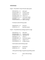
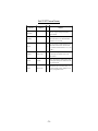
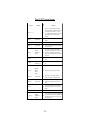
1
BNC
555 Series
Pulse Generator
User's Manual
Berkeley Nucleonics Corporation
2955 Kerner Blvd.
San Rafael, CA 94901
Phone (415) 453-9955
Fax (415) 453-9956
www.berkeleynucleonics.com
Contents
INTRODUCTION .................................................................................... 1
Technical Support .............................................................................................................. 1
Parts List ............................................................................................................................ 1
Warranty ............................................................................................................................ 1
Safety Issues ...................................................................................................................... 1
CONTROLS & CONNECTORS .............................................................. 5
Front Panel ......................................................................................................................... 5
Display Layout and Indicators ............................................................................................ 5
Keypads .............................................................................................................................. 5
Parameter Adjustment Knob ............................................................................................. 6
BASIC OPERATION ............................................................................... 7
Overview ............................................................................................................................ 7
QuickStart ........................................................................................................................... 8
Selecting Menus ................................................................................................................ 9
Selecting Menu Items ....................................................................................................... 9
Numeric Input Mode ......................................................................................................... 9
Item Edit Mode ................................................................................................................ 10
Alphanumeric Input Mode .............................................................................................. 10
MENUS ................................................................................................. 11
CHANNEL Menu .............................................................................................................11
Enable/Disable ...................................................................................................................11
Timing Parameters ............................................................................................................11
Pulse Configuration ...........................................................................................................11
Special Functions .............................................................................................................. 12
Gated Operation ............................................................................................................... 12
MODE Menu ................................................................................................................... 12
Modes ............................................................................................................................... 12
RATE Menu ..................................................................................................................... 13
To Period .......................................................................................................................... 13
GATE/TRIGGER Menu ................................................................................................. 13
Gate/Trigger Mode .......................................................................................................... 14
-i-
SYSTEM Menu ............................................................................................................... 14
Computer Communication Parameters ........................................................................... 14
Keypad Controls .............................................................................................................. 15
Miscellaneous .................................................................................................................. 15
STORE Menu .................................................................................................................. 15
Storing a Configuration..................................................................................................... 15
Configuration # ................................................................................................................. 16
Name ................................................................................................................................. 16
RECALL Menu ............................................................................................................... 16
Recalling a Configuration ................................................................................................. 16
Configuration # ................................................................................................................. 16
Name ................................................................................................................................. 16
AUXILIARY Menus ........................................................................................................ 17
BASIC OPERATION ............................................................................. 18
COMPUTER INTERFACE .................................................................... 21
Serial Port Pinout ............................................................................................................. 21
Programming Command Types and Format ................................................................... 21
IEEE 488.2 Common Command Format ......................................................................... 21
SCPI Command Keywords ............................................................................................... 22
SCPI Command and Query Format ................................................................................. 22
SCPI Keyword Separator ................................................................................................. 23
SCPI Option Keyword ...................................................................................................... 23
SCPI Specific and Implied Channel ................................................................................. 23
SCPI Parameter Types ..................................................................................................... 23
Error Codes ...................................................................................................................... 23
INTERFACE EXAMPLES ..................................................................... 25
SPECIFICATIONS ................................................................................ 31
Internal Rate Generator ................................................................................................. 31
Channel Timing Parameters ............................................................................................ 31
Output Channel Parameters ............................................................................................ 31
External Trigger and Gate .............................................................................................. 31
Computer Interface ......................................................................................................... 32
General ............................................................................................................................. 32
MENU SUMMARY ................................................................................ 33
MAINTENANCE ................................................................................... 37
- ii -
CUSTOM FEATURES ........................................................................... 39
35 Volt Option .................................................................................................................. 39
- iii -
- iv -
INTRODUCTION
This manual is designed to familiarize you with the Berkeley Nucleonics Model 555 pulse
generator. Rather than the usual array of knobs and switches, the 555 uses a menu-driven user
interface with “on-line” help -- once you learn the basics of operating your 555, you may never
need to refer to this manual again.
The 555 has some unique features that are designed exclusively for use as a laser trigger signal
generator, but can also be used as a general purpose pulse generator. Because it employs a
flexible microprocessor-controlled architecture, the 555 can be customized to fit your exact
requirements -- contact Berkeley Nucleonics for details.
Technical Support
For questions or comments about operating the 555 -- contact Berkeley Nucleonics via one of
the following methods.
- Phone - (415)453-9955
- Fax - (415)453-9956
- Internet - www.berkeleynucleonics.com
Parts List
The following parts are included with the 555 -- contact Berkeley Nucleonics if any parts are
missing.
- 555 Pulse Generator
- AC Power Cord
- User’s Manual
Warranty
In addition to a 30-day money back guarantee, the 555 has a one-year limited warranty from
the date of delivery. This warranty covers defects in materials and workmanship. Berkeley
Nucleonics will repair or replace any defective unit. Contact us for information on obtaining
warranty service. Warranty does not apply to defects resulting from:
- Improper or inadequate maintenance or calibration;
- Unauthorized modification or misuse;
- Operation outside of the published environmental specifications for the product;
- Improper site preparation or maintenance.
-1-
Berkeley Nucleonics does not warrant the operation of this product to be uninterrupted or error
free. This product is not intended for medical or life-support use, for the detonation of
explosive devices, or for any other application that could cause bodily harm in the event of a
product malfunction. The user assumes all risks associated with such use of this product.
Safety Issues
Normal use of test equipment presents a certain amount of danger from electrical shock because testing must be performed where exposed voltage is present. An electrical shock causing
10 milliamps of current to pass through the heart will stop most human heartbeats. Voltage as
low as 35 VDC or RMS AC should be considered dangerous and hazardous since it can
produce a lethal current under certain conditions. Higher voltages pose an even greater threat
because such voltage can easily produce a lethal current. Your normal work habits should
include all accepted practices that will prevent contact with exposed high voltage, and steer
current away from your heart in case of accidental contact with a high voltage. You will significantly reduce the risk factor if you know and observe the following safety precautions:
1. To avoid the risk of electric shock, do not remove the instrument cover. Servicing of the instrument should only be performed by trained, qualified personnel.
2. Do not position the instrument in such a manner that makes it difficult to remove
the AC power cord.
3. Use an insulated floor material or a large, insulated floor mat to stand on, and an
insulated work surface on which to place equipment. Make certain such
surfaces are not damp or wet.
4. Use the time-proven “one hand in the pocket” technique while handling an
instrument probe. Be particularly careful to avoid contact with metal objects
that could provide a good ground return path.
5. When testing AC powered equipment, remember that AC line voltage is usually
present on power input circuits, such as the on-off switch, fuses, power transformer etc.
-2-
6. Never work alone. Someone should always be nearby to render aid if necessary. Training in CPR first aid is highly recommended.
7. Safety symbols used on the instrument
- Instruction Manual symbol
(user must refer to the instruction manual)
- On/Standby switch symbols:
On
Standby
-3-
-4-
CONTROLS & CONNECTORS
Front Panel
Display Layout and Indicators
A 4 line x 20 character vacuum fluorescent display module displays parameters and status
information. The status information is located in the upper-left corner of the display, between
the two brackets. There are three enunciators:
• Vertical Arrow
Indicates there are additional pages to the current menu.
• Blinking Light
Indicates the unit is actively generating pulses, or armed and
waiting for an external trigger.
• Musical Note
Indicates the function key has been pressed.
The upper-right side of the display contains the title of the currently displayed menu. The rest of
the display is used for system parameters. The display brightness may be adjusted allowing the
instrument to be used under various lighting conditions.
Keypads
Three keypad areas provide fast access to various menus and easy editing of system parameters.
• Channel Keypad
Provides one touch access to the menus for setting up the
channel parameters. Pressing the appropriate letter will display the parameters for the corresponding channel.
• Arrow Keypad
The up/down arrows are used to increment/decrement the
current parameter (indicated by the blinking cursor). The position of the cursor controls the step size for each increment.
The right/left arrow moves the cursor to different positions
within the current parameter. The NEXT key selects the next
parameter in the currently displayed menu. The blue Function
key allows the keys to select the blue function.
• Numeric Keypad
Allows numbers and alphanumeric values to be entered.
When entering alphanumeric values, pressing a key will display the first letter shown on the keypad. Repeated key
presses will toggle through all the letters, both upper and
lower case, shown on the keycap.
-5-
To enter two letters which appear on the same keycap, select
the first character, then use the right arrow to shift to the next
position and enter the next letter. When data entry is complete the ENTER key must be pressed.
Parameter Adjustment Knob
An alternate to the Arrow Keypad, the Parameter Adjustment Knob may be used to adjust the
current parameter. The step size is controlled by the position of the cursor, however turning the
knob faster will increase the step size. Pushing the knob will perform functions similar to the
NEXT key and switch to the next parameter in the currently displayed menu.
-6-
Basic Operation
Arm
Overview
Gate
*
Start
To
Internal System Timer
and System Mode
Generator
Internal
To Pulse
RUN
Command
External
Input
Start
**
Gate
Arm
Channel Timers and Channel
Mode Generators
Output
MUX
Output
Pulses
*Start
source is: RUN button in Internal Modes
* Start source is: RUN button in Internal Modes
External
input
in External
Trigger
External
input
i n External
triggermodes
modes
** Channels
armed
RUNbutton.
button. In
In single
single shot
**Channels
areare
armed
byby
thetheRUN
shotandburst
and burstmodes
modes
channells may be rearmed by pressing the RUN a second time.
channels may be rearmed by pressing the RUN button.
The Model 555 Pulse Generator is designed to provide maximum flexibility, while maintaining a
simple interface. A basic understanding of the architecture of the instrument will aid in fully
exploiting its capabilities. Referring to the figure above, the timing generator is divided into two
sections: the Internal System Timer & Mode Generator and the Channel Timer & Mode
Generator.
The Channel Timer functions as a 'non-retriggerable, delayed, one shot' pulse generator. This
means that the timer will only generate one delayed pulse for every start pulse received. Once
the channel timer has started counting, additional start pulses will be ignored until the pulse has
been completed (nonretriggerable). The start pulse for each channel is provided by the internal
To pulse generated by the Internal System Timer. Whether or not a pulse is generated for each
To pulse is determined by the Channel Mode Generator. Standard modes include:
Normal
a pulse is generated for each To pulse
Single Shot
a pulse is generated at the first To pulse
-7-
Burst
Divide-by-n
a pulse is generated for each To pulse, 'n' times, after which
output is inhibited
a pulse is generated every nth To pulse
Different modes may be selected for each output, allowing a wide variety of output combinations. Each output may also be independently disabled or gated (using the external trigger
input).
The System Timer functions as a non-retriggerable, multivibrator pulse generator. This means
that once started, depending on the mode, the timer will produce pulses continuously. Before
pulses will be generated, the timer must be armed and then receive a start pulse. Arming the
counter is done by pressing the RUN key. With external trigger disabled, the RUN key also
generates the start command for the counter. With external trigger enabled, the external trigger
provides the start pulse. In either case, once started, the counter operation is determined by the
System Mode Generator. Standard modes include:
Continuous
once started To pulses are generated continuously
Single Shot
one To pulse is generated for each start command
Burst Mode
'n' To pulses are generated for each start command
Duty Cycle
once started To pulses cycle on and off continuously
The To pulses are distributed to all of the start inputs of the Channel Timer and Mode Generators.
QuickStart
The default mode (channel mode = normal, system mode = continuous, and external trigger
disabled) of the Model 555 generates a continuous stream of pulses when started by the RUN
key. The output status is given in the upper-left corner of the display. A blinking light indicates
pulses are being produced.
To generate a specific pulse train in the default mode:
• Enter the output channel menu by pressing the appropriate letter key. Set the
desired pulsewidth and delay. Repeat for each output.
-8-
•
•
Enter the RATE menu, by pressing the FUNCTION key and then the "4" key.
Set the desired pulse period. Note that in general the pulse delay plus
pulsewidth should be less than the period.
Press the RUN key.
Selecting Menus
Parameters are grouped in menus, selectable using the function keys. To select the output
channel parameters press the letter key corresponding to the desired channel. To select blue
menus press the FUNCTION key and then the key corresponding to the desired blue function.
Menus may include a number of different pages. Each page contains up to four parameters.
The status block in the upper-left corner of the display shows a vertical arrow if the current
menu contains additional pages. To select the next page, select the same menu button again,
pressing the FUNCTION key and blue function again for higher-order menus.
Selecting Menu Items
Within a menu, the blinking cursor indicates the current menu item for editing. The NEXT key
or pressing the adjustment knob will select a different menu item.
Numeric Input Mode
When the current item is numeric, the system enters the Numeric Input Mode. In this mode
data may be edited in one of three ways. Using the arrow keypad, the Left and Right arrow
keys are used to select a digit to edit. The selected digit blinks to identify itself as the active
digit. The Up and Down arrow keys are then used to increment or decrement this digit. Alternately, after using the Left and Right arrow keys to select an active digit, the adjustment knob
may be used to increment and decrement this digit. The adjustment knob features speed
dependent resolution. Slow rotation will increment or decrement the active digit by one. As
you increase the speed of rotation, the parameter will be 10 to 1000 times faster depending on
the speed.
The last entry mode is using the numeric keypad. Enter the number, including decimal point
using the numeric keypad. When complete, enter the number using the ENTER key. Errors
may be corrected using the backspace key or to start over press the clear key (CLR). Pressing
the CLR key a second time will exit the numeric keypad mode and restore the original number.
-9-
Item Edit Mode
When the current item is non-numeric, the Up and Down arrow keys are used to select among
different options for the parameter. The adjustment knob may also be used to change the
selection. If the item is an on/off toggle, the Up arrow (CW adjustment knob) enables the item
and the Down arrow (CCW adjustment knob) disables the item.
Alphanumeric Input Mode
When the current item is alphanumeric, the system enters the Alphanumeric Input Mode. In this
mode, data is entered using the alphanumeric keypad. When entering alphanumeric values,
pressing a key will display the first letter shown on the keypad. Repeated key presses will
toggle through all the letters, both upper and lower case, shown on the keycap. To enter two
letters which appear on the same keycap, select the first character, then use the right arrow to
shift to the next position and enter the next letter. The Left and Right arrow keys may be used
to position the cursor to edit any character. When data entry is complete, the ENTER key must
be pressed. The keys contain the following characters.
•
•
•
•
•
•
•
•
•
•
•
•
1
2
3
4
5
6
7
8
9
0
.
-
1234567890
ABCabc2
DEFdef3
GHIghi4
JKLJkl5
MNOmno6
PQRSpqrs7
TUVtuv8
WXYZwxyz9
0123456789
.,#$%&?
- + * / space
- 10 -
MENUS
CHANNEL Menu
CHANNEL Menus
Timing Parameters
Pulse Configuration
Special Functions
Gated Operation
Enable
Enable
Enable
Enable
Gate Enable
Polarity
Pulsewidth
Output Type
Mode
Delay
Output Level
Divide-by-N
# / Burst
Enable/Disable
The top of each Channel menu page is a parameter to enable or disable the output of the
channel. This affects only the output of the current channel.
Timing Parameters
• PULSEWIDTH
• DELAY
Sets the width of the active portion of the pulse.
Sets the delay from the internal To or external trigger to the
start of the pulse.
*NOTE: The pulsewidth + delay + 250 ns (hardware reset constant) must be
less than the To period. Therefore if the sum exceeds To period, the correct
pulses will be generated but at a rate slower than the To rate.
Pulse Configuration
• POLARITY
• OUTPUT TYPE
• OUTPUT LEVEL
Sets the pulse to active high or active low.
Selects between the high speed TTL/CMOS compatible output or the slower adjustable output.
Sets the voltage level when the adjustable output is selected.
*NOTE: The unit does not generate negative output voltages. An active high
TTL/CMOS pulse is: 0v - 5v - 0v. An active low pulse is: 5v - 0v - 5v. The
adjustable output has a slower rise/fall time than the TTL/CMOS output and
should be used only when the adjustable voltage or the extra current is
needed.
- 11 -
Special Functions
• MODE
• #/BURST
• DIVIDE-BY-N
Selects the channel output mode: continuous, single shot,
burst, or divide-by-n.
Sets the number of pulses to be generated in the burst mode.
Sets the divisor for the divide-by-n mode.
Gated Operation
• GATE
• POLARITY
Enables/disables the channel gating using the external trigger
input. This function is independent of any other use of the
trigger input. Care should be taken to insure that all uses of
the trigger are compatible.
Sets the gate to active low or active high.
*NOTE: The gate function disables the channel from being triggered by the
To pulse. To prevent partial pulses from being generated, the gate does not
disable the channel timers. Thus, if a pulse has already started when the
gate disables the channel, the pulse will continue normal output but will not
restart on the next To pulse.
MODE Menu
MODE Menus
To Mode
To Mode
To Mode
To Mode
MODE: Continuous
MODE: Single Shot
MODE: Burst
MODE: Duty Cycle
# / Burst
Oscillator
DC On
OSC Out
DC Off
OSC In
Modes
• MODE
• #/BURST
Selects the To mode: Continuous, Single Shot, Burst or Duty
Cycle mode.
Sets the number of pulses to be generated when in the Burst
mode.
- 12 -
• DC ON
Sets the number of pulses to be generated each on cycle
when in the Duty Cycle mode..
Sets the number of pulses to skip each off cycle when in the
Duty Cycle mode.
• DC OFF
*NOTE: Any mode may be started by either the RUN key in the internal
trigger mode or armed by the RUN key and started by an external trigger in
the external trigger mode. In the single shot and burst modes, (internally
triggered) the unit disarms itself at the end of the pulse train. Pressing the
RUN key after the unit has been disarmed will generate a new pulse train.
RATE Menu
Rate Menu
To Period
To Period
To Period
• PERIOD
Sets the To period.
GATE/TRIGGER Menu
GATE/TRIGGER Menu
Gate/Trigger Mode Gate/Trigger Mode Gate/Trigger Mode
MODE: Disabled
MODE: Triggered
MODE: Gated
THRESHOLD
THRESHOLD
THRESHOLD
EDGE
POLARITY
- 13 -
Gate/Trigger Mode
• MODE
• THRESHOLD
• EDGE
• POLARITY
Selects external input usage for controlling To: disabled, edge
triggered or level gated.
Sets the voltage threshold for the external input. This level is
applied to all uses of the external input.
Selects rising or falling edge for the trigger mode.
Selects active high or active low in the gated mode.
*NOTE: When the gate disables the System Timer, the timer is reset. The gate
edge to enable the timer will restart the System Timer, which synchronizes the
To pulse to the gate and minimizes jitter relative to the gate. The trigger
threshold applies to all uses, channel and system, of the trigger/gate input.
SYSTEM Menu
SYSTEM Menus
Comm. Parameters
Keypad
Parameters
Baud Rate
Key Repeat Rate
Echo Enable
Key Volume
Decimal Mark
GPIB Address
Knob Volume
LCD Brightness
Misc. Parameters
Computer Communication Parameters
• BAUD RATE
• ECHO
• GPIB ADDRESS
Selects the baud rate for the RS232 interface.
Selects whether to echo characters back to the host computer
or not.
Selects the GPIB address.
*NOTE: The unit will not respond to computer commands unless the appropriate BAUD rate or GPIB address is selected.
- 14 -
Keypad Controls
• KEY REPEAT RATE Sets the rate at which the keys will repeat when held down.
This is most useful when using the Up/Down arrows to
change parameters.
• KEY VOLUME
Sets the key click volume.
• KNOB VOLUME Sets the parameter adjustment knob click volume.
*NOTE: The key repeat rate is fairly accurate (better than one millisecond)
and may be used to increase/decrease a parameter at a set rate.
Miscellaneous
• AUTO
Auto run startup function - allows unit to automatically generate pulses after startup is complete.
• DECIMAL MARK Selects a dot or a comma for the decimal point.
• LCD BRIGHTNESS Sets the LCD brightness.
*NOTE: The decimal point may be replaced with a comma for display purposes, but the computer command interface always uses a decimal point.
STORE Menu
STORE Menu
Store Menu
Configuration #
Name
Help Line
Storing a Configuration
Use the following procedure to store a complete system configuration:
• To enter the Store Menu, press the store button (function + store).
• Set all parameters to the desired value.
• Select a configuration number.
*NOTE: The number of storage locations is model dependent; see the specifications for your model. You cannot store to the zero location, as that
contains the factory default values.
- 15 -
• Label the configuration as desired. Press enter key to save label.
• From the Store menu, press the store button (function + store).
Configuration #
Specifies the location to store the current system configuration. Numbers range from 1 to n,
where "n" is the number of stored configuration.
Name
Prior to storing the system configuration, a label may be added to help identify the configuration
later. Enter a new label using the alphanumeric keypad.
RECALL Menu
RECALL Menu
Recall Menu
Configuration #
Name
Help Line
Recalling a Configuration
Use the following procedure to recall a stored or default system configuration:
• To enter the Recall Menu, press the recall button (function + recall).
• Select a configuration number. Note that configuration 0 is the factory default setting.
• From the Recall Menu, press the recall button (function + recall).
Configuration #
Specifies the location of the system configuration. Numbers range from 0 to n, where n is the
number of stored configuration. Zero is the factory default values.
Name
A label may be added to help identify the configuration. This is a read only field. The label is
changed in the Store menu.
*NOTE: The number of storage locations is model dependent; see the specifications for your model.
- 16 -
AUXILIARY Menus
AUX 1 Menu
Pulsewidth
Delay
Ch A Pulsewidth
Ch A Delay
Ch B Pulsewidth
Ch B Delay
Ch C Pulsewidth
Ch C Delay
Ch DPulsewidth
Ch D Delay
The auxiliary menus provide a location for special functions to be added for semi-custom units.
In addition, the Auxiliary 1 menu provides summary menus for pulsewidth and delay. Thus,
providing a location to change all the delays and/or pulsewidths without having to go through all
the channel menus.
*NOTE: The Auxiliary 1 Menu has summary pages for pulsewidth and delay,
which allow you to change all the widths or delays from one menu.
- 17 -
- 18 -
BASIC OPERATION
With the channels in the normal mode, operation of the unit is controlled by the system mode
and the external trigger. The basic modes are as follows:
Operational Modes w/o External Trigger
Continuous
RUN/STOP button starts and stops a continuous pulse
stream at the rate specified by the RATE menu. This corresponds to the normal output mode for most pulse generators.
Single Shot
RUN/STOP button generates a single pulse.
Burst
RUN/STOP button generates a stream of "n" pulses, where
"n" is specified by the Burst parameter. The rate is specified
in the RATE menu. Pressing the RUN/STOP button while the
burst is in process will stop the output. After the burst has
been completed, pressing the RUN/STOP button will generate another burst.
Duty Cycle
RUN/STOP button starts a continuous pulse stream which
oscillates for the "n" pulses and off for "m" pulses, where "n"
and "m" are specified by the ON and OFF parameters, respectively. The rate is specified in the RATE menu.
Operation Modes w/External Trigger
Continuous
RUN/STOP button arms unit. The first trigger received starts
continuous pulse stream at the rate specified by the RATE
menu. Additional triggers are ignored. Pressing the RUN/
STOP button a second time will stop and disarm the instrument.
- 19 -
Single Shot
RUN/STOP button arms unit. Generates a pulse for every
external trigger received. Press the RUN/STOP button a
second time to disarm the instrument. This corresponds to
the normal externally triggered mode for most pulse generators.
Burst
RUN/STOP button arms unit. Generates a stream of "n"
pulses where "n" is specified by the Burst parameter for every
external trigger received. The rate is specified in the RATE
menu.
Duty Cycle
RUN/STOP button arms unit. The first trigger starts a continuous pulse stream which oscillates on for "n" pulses and off
for "m" pulses, where "n" and "m" are specified by the ON
and OFF parameters respectively. The rate is specified in the
RATE menu. Additional triggers are ignored.
- 20 -
COMPUTER INTERFACE
Serial Port Pinout
1. No Connection
2. Tx - Transmit (to computer)
3. Rx - Receive (from computer)
4. DTR - connected to pin 6
5. Ground
6. DSR - connected to pin 4
7. RTS - connected to pin 8
8. CTS - connected to pin 7
9. No connection
A standard straight through cable is used with most PCs.
Programming Command Types and Format
The Model 555 Pulse Generators use two types of programming commands: IEEE 488.2
Common Commands and Standard Commands for Programmable Instruments (SCPI). The
format is the same for both the RS232 interface and the optional IEEE 488 interface.
Hyperterminal (in Windows) or any other generic terminal program may be used to interactively
test the commands using the RS232 interface. The format of each type is described in the
following paragraphs.
IEEE 488.2 Common Command Format
The IEEE 448.2 Common Commands control and manage generic system functions such as
reset, self-test, and identification. Common commands always begin with the asterisk (*)
character and may include parameters. The parameters are separated from the command
pneumonic by a space character. For Example:
*RST
*RCL 1
*IDN?
<cr> <lf>
<cr> <lf>
<cr> <lf>
- 21 -
SCPI Command Keywords
The commands are shown as a mixture of upper and lower case letters. The upper case letters
indicate the abbreviated spelling for the command. You may send either the abbreviated version
or the entire keyword. Upper and/or lower case characters are acceptable.
For example: If the command keyword is given as POLarity, the POL and POLARITY are
both acceptable forms; truncated forms such as POLAR will generate an error; polarity, pol,
and PolAriTy are all acceptable as the pulse generator is not case sensitive.
SCPI Command and Query Format
SCPI commands control and set instrument specific functions such as setting the pulsewidth,
delay and period. SCPI commands have a hierarchical structure composed of functional
elements that include a header or keywords separated with a colon, data parameters and
terminators.
:PULSE1:STATE ON
<cr> <lf>
:PULSe1:WIDth 0.000120
<cr> <lf>
:PULSe:POL NORMal
<cr> <lf>
A colon always separates one keyword from the next lower-level keyword. A space must be
used to separate the keyword header from the first parameter. If more than one parameter is
used, you must separate adjacent parameters with a comma.
Any parameter may be queried by sending the command with a question mark appended.
For example: :PULSE1:STATE?
Will return:
1 <cr> <lf>
Will return:
:PULSE1:WIDT? <cr> <lf>
0.000120000 <cr> <lf>
Will return:
:PULSE1:POL? <cr> <lf>
NORM <cr> <lf>
- 22 -
SCPI Keyword Separator
A colon ( : ) must always separate one keyword from the next lower-level keyword.
SCPI Option Keyword
Optional keywords and/or parameters appear in square brackets ( [ ] ) in the command syntax.
Note that the brackets are not part of the command and should not be sent to the pulse generator. When sending a second level keyword without the optional keyword, the pulse generator
assumes that you intend to use the optional keyword and responds as if it had been sent.
SCPI Specific and Implied Channel
Some commands, such as PULSe, allow specifying a channel with an optional numeric keyword
suffix. The suffix will be shown in square brackets [ 1 / 2 ]. The brackets are not part of
command and are not sent to the pulse generator. The numeric parameters correspond to the
following channels: 0 = To, 1 = ChA, 2 = ChB, etc. Only one channel may be specified at a
time.
If you do not specify the channel number, the implied channel is specified by the
:INSTrument:SELect command or the last referenced channel. After power-up or reset (*RST)
The instrument default is channel #1.
SCPI Parameter Types
The following parameter types are used:
<numeric value>
Accepts all commonly used decimal representation of numbers including optional signs, decimal points and scientific notation:
123, 123e2, -123, -1.23e2, .123, 1.23e-2, 1.2300E-01
<boolean value>
Represents a single binary condition that is either true or false. True is
represented by a 1 or ON; false is represented by a 0 or OFF. Queries return 1 or 0.
- 23 -
<identifier>
Selects from a finite number of predefined strings.
Error Codes
The unit responds to all commands with either:
or
ok <cr> <lf>
?n <cr> <lf>
Where "n" is one of the following error codes:
1
2
3
4
5
6
7
Incorrect prefix, i.e. no colon or * to start command.
Missing command keyword.
Invalid command keyword.
Missing parameter.
Invalid parameter.
Query only, command needs a question mark
Invalid query, command does not have a query form.
- 24 -
Interface Examples
Example 1) - 20 ms pulsewidth, 2.3 ms delay, 10 Hz, internal, continuous operation.
:PULSE1:STATE ON <cr> <lf>
:PULSE1:POL NORM <cr> <lf>
:PULSE:WIDT 0.020 <cr> <lf>
:PULSE1:DELAY 0.0023 <cr> <lf>
:PULSE0:MODE CONT <cr> <lf>
:PULSE0:PER 0.1 <cr> <lf>
:PULSE0:EXT:MODE DIS <cr> <lf>
enables channel A
sets polarity to active high
sets pulsewidth to 20 ms
sets delay to 2.3 ms
sets system mode to continuous
sets period to 100 ms (10 Hz)
disables the external trigger
To start the pulses use either of the following commands:
:PULSE0:STATE ON <cr> <lf>
:INST:STATE ON <cr> <lf>
starts the pulses
alternate form to start pulses.
Example 2) - 25 ms pulsewidth, 0 is delay, external trigger, one pulse for every trigger.
:PULSE1:STATE ON <cr> <lf>
:PULSE1:POL NORM <cr> <lf>
:PULSE:WIDT 0.000025 <cr> <lf>
:PULSE1:DELAY 0 <cr> <lf>
:PULSE0:MODE SING <cr> <lf>
:PULS:EXT:LEV 2.5 <cr> <lf>
:PULS:EXT:EDGE RIS <cr> <lf>
enables channel A
sets polarity to active high
sets pulsewidth to 25 ms
sets delay to 0
sets system mode to single shot
sets trigger level to 2.5v
set to trigger on rising edge
To arm the instrument use either of the following commands:
:PULSE0:STATE ON <cr> <lf>
:INST:STATE ON <cr> <lf>
arms the instrument
alternate form
A software generated external trigger can be generated by using the following command:
*TRG <cr> <lf>
generates a software external trigger
- 25 -
Model 555 SCPI Command Summary
Keyword
Parameter
Std/
New
Comments
:INSTrument
Std
Subsystem. Supports treating each channel as a
logical instrument.
:CATalog?
Std
Query only. Returns a comma-separated list of the
names of all channels. A two channel instrument
would return: To, ChA, ChB.
:FULL?
Std
Query only. Returns a comma-separated list of the
names of all channels and their associated number.
A two channel instrument would return: To, 0, ChA,
1, ChB, 2.
:NSELect
<numeric value>
Std
Selects a channel using the channel's numeric value.
All channel specific commands will refer to the
selected channel.
:SELect
<identifier>
Std
Selects a channel using the channel's identifier string.
All subsequent channel specific commands will refer
to the selected channel.
:STATe
<boolean value>
Std
Enables/Disables the selected channel output. If To
is selected all output is affected. Enabling To is the
same as pressing the RUN button.
- 26 -
Model 555 SCPI Command Summary
Keyword
Parameter
Std/
New
Comments
Std
Subsystem. Contains commands to control the
output pulse generation. Commands without suffix
refer to the currently selected logical instrument. See
INSTrument subsystem.
<boolean value>
Std
Enables / Disables the output for all channels.
Command is the same as pressing the RUN button.
:BCOunter
<numeric value>
New
Burst Counter. Number of pulses to generate in the
Burst mode.
:PCOunter
<numeric value>
New
Pulse Counter. Number of pulses to generate during
on cycle of the Duty Cycle mode.
:OCOunter
<numeric value>
New
Off Counter. Number of pulses to inhibit output
during the off cycle of the Duty Cycle mode.
:OSCillator
INTernal / EXTernal
New
Selects the To oscillator source: Internal 80 MHz or
external 10 MHz.
New
Subsystem. Contains the commands to define the
system use of the external input.
:PULSe [0]
: STATe
:EXTernal
:LEVel
<numeric value>
Sets the trigger threshold. Value is in volts, with a
range of 200 - 300 volts. Note: This command is an
New
alias to :GATE:AMPLitude; both adjust the threshold
for the external input.
- 27 -
Model 555 SCPI Command Summary
Keyword
Parameter
:PULSe [1 / 2 / n]
Std/New
Comments
Std
Subsystem. Contains commands to control the
output pulse generation. Valid suffix range depends
on the number of channels (CHA = 1, ChB = 2,
etc). Command without suffix refers to the currently
selected logical instrument. See INSTrument
subsystem.
:STATe
<boolean value>
Std
Enables/Disables the output pulse for selected
channel.
:WIDTh
<numeric value>
Std
Sets the width or duration of the output pulse.
:DELay
<numeric value>
Std
Sets the time from the start of the To period to the
first edge of the pulse.
:POLarity
NORMal /
COMPlement /
INVerted
Std
Sets the polarity of the pulse. For NORMal
operation the second nominal state is more positive
than the first. COMPlement and INVerted are
aliases. For both, the second state is more negative
than the first.
New
Subsystem. Contains command to control output
mode.
:OUTPut
:MODe
TTL /
ADJustable / 35 V
New
Selects output mode: TTL/CMOS, Adjustable or 35
Volt.
:AMPLitude
<numeric value>
New
Sets Adjustable output level.
:CMODe
NORMal /
SINGle /
BURSt /
DIVide
New
Channel Mode. Sets the channel output mode.
:BCOunter
<numeric value>
New
Burst Counter. Sets the number of pulses to
generate when channel is in the BURST mode.
:DCOunter
<numeric value>
New
Divide Counter. Sets the number of pulses to
generate when the channel is in the divide-by-n
mode.
New
Channel Gate Subsystem. Contains commands to
control using the gate input to control the output
channel.
:CGATE
:STATe
<boolean value>
New
Enables/disables the use of the channel gate function.
:POLarity
NORMal /
COMPlement /
INVerted
New
Sets the polarity of the gate signal. NORMal output
is active when gate signal is high. COMPlement and
INVerted are aliases. For both, the output is active
when gate signal is low.
- 28 -
Model 555 SCPI Command Summary
Keyword
Parameter
:UPDate
Keyword
Subsystem. Contains commands to control the
display.
<numeric value>
Std
Controls intensity of display. Range is 0 to 1, where
0 is off and 1 is full intensity.
Query
New
Query only. Forces update of display.
Parameter
:SYSTem
:STATe
:VOLume
Query
<boolean value>
<numeric value>
:COMMunicate
:GPIB
:ADDRess
Std/
New
Comments
Std
:BEEPer
:STATe
Comments
Std
:DISPlay
:BRIGhtness
Std/
New
<numeric value>
[<numeric value>]
:SERial
New
Query only. Returns the state of the machine:
returns ACTIVE if the machine is armed and/or
generating pulses or IDLE if the machine has been
disarmed, followed by a counter of the number of
bursts generated by the machine. The counter
ranges from 0-99 and rolls back to 0 after the 99th
burst group has been completed.
Std
Subsystem. Controls the audible beeper.
Std
Enables/disables the beeper.
Std
Sets the volume of the beeper. Range is 0 to 1,
where 0 is off and 1 is maximum volume.
Std
Subsystem. Controls the RS232 and GPIB
interfaces.
Std
Subsystem. Controls the physical configuration of
the GPIB port.
Std
Sets the GPIB address of the instrument.
Std
Subsystem. Controls the physical configuration of
the RS232 port.
:BAUD
4800 /
9600 /
19200 /
38400 /
Std
Sets the baud rate for both receiving and transmitting
using the RS232 port. Valid rates are 4800, 9600,
19200 and 38400.
:ECHO
<boolean value>
New
Enables/Disables transmission of characters received
by the RS232 port.
:KLOCk
<boolean value>
New
Locks the keypad.
:AUTorun
<boolean value>
New
After power-up, unit will start generating pulses
automatically.
Std
Query only. Returns SCPI version number in the
form: YYYY.V ex. 1999.0
:VERSion?
- 29 -
IEEE 488.2 Common Commands
Mnemonic
Command Name
*IDN?
Identification Query
*RCL
Recall Command
*RST
Reset Command
*SAV
Save Command
*TRG
Trigger
Parameters
Comments
Queries the Pulse Generator Identification. The ID
will be in the following format:
model#-option#-version#
Restores the state of the Pulse Generator from a
<numeric value> copy stored in local nonvolatile memory (0 through
10 are valid memory blocks).
Resets the Pulse Generator to the default state.
Stores the current state of the Pulse Generator in
<numeric value> local nonvolatile memory (1 through 10 are valid
memory blocks).
Generates a software trigger pulse. Operation is the
same as receiving an external trigger pulse.
- 30 -
SPECIFICATIONS
Internal Rate Generator
• Trigger Modes
• Rate
• Resolution
• Accuracy
• Jitter
• Burst Range
• On/Off Cycle Range
Single shot, continuous, burst, duty cycle
1?? s - 99.99999999 s (.01 Hz to 1 Mhz)
100 ns
1 ns + .0001 x period
1 ns (RMS)
1 - 50,000 pulses
1 - 50,000 pulses
Channel Timing Parameters
• Delay
0 - 99.999999999s (2 & 4 Channel Units)
0 - 20 s (8 Channel Unit; channels 1 & 2)
0 - 13 s (8 Channel Unit; channel 3)
0 - 1.6 s (8Channel Unit; channels 4 - 8)
• Pulsewidth
10 ns - 99.999999999 s (2 & 4 Channel Units)
10 ns - 20 s (8 Channel Unit; channels 1 &2)
10 ns - 13 s (8 Channel Unit; channel 3)
10 ns - 1.6 s (8 Channel Unit; channels 4 - 8)
• Resolution
1 ns
• Accuracy
2 ns + .0001 x delay
• Timebase
80 MHz
• Jitter
1 ns (RMS)
Output Channel Parameters
• Impedance
50 ohm
• Output
TTL/CMOS
Adjustable 2.00 V - 12 V into high impedance load
Independently adjustable for each channel
• Slew Rate
> 1 V/ns TTL/CMOS Mode
> .1 V/ns Adjustable Mode
• Channel Modes
Single shot, normal, burst, divide-by-n
• Burst Range
1 - 50,000 pulses
• Divide-by-n Range
1 - 50,000
- 31 -
External Trigger and Gate
• Rate
• Threshold
• Insertion Delay
• Jitter
• Trigger Slope
• Gate
• Impedance
Computer Interface
• RS232
• GPIB (optional)
DC - 1 MHz
100 mV - 12V
< 250 ns
15 ns (RMS)
Rising or falling edge
Active low or active high
1000 ohm
4800, 9600, 19200, 38400 Baud. All instrument functions
and settings may be controlled over the interface bus.
IEEE 488.2
General
• Configuration Memory Twelve (12) complete configurations may be stored and
recalled from the front panel or the computer interface.
• Weight
6 lbs.
• Dimensions
8.25" x 8.25" x 5.5"
• Power
100 - 240 V~, 50 - 60 Hz, 1 A max
• Storage Temperature -40 degrees C to +85 degrees C
• Class 1 Equipment II Earth grounded mains supply required.
• Pollution Degree II
• Overvoltage Category II
• Safety
Designed in compliance with EN 61010-1
• EMC
Innumity: EN61326-1 : 2000 - General Requirements
Emissions: EN55011 : 1998 - Class B
Normal Operating Conditions
• Indoor use only.
• Altitude up to 2 000 m.
• Temperature 5 degrees C to 40 degrees C.
• Maximum relative humidity 80% for temperatures up to 31 degrees C; decreasing
linearly to 50% relative humidity at 40 degrees C.
• Mains supply voltage fluctuation up to +10% of the nominal voltage.
- 32 -
MENU SUMMARY
CHANNEL Menus
Timing Parameters Pulse Configuration
Enable
Special Functions
Gated Operation
Enable
Enable
Enable
Polarity
Pulsewidth
Output Type
Mode
Gate Enable
Delay
Output Level
Divide-by-N
# / Burst
Polarity
MODE Menus
To Mode
To Mode
To Mode
To Mode
MODE: Continuous
MODE: Single Shot
MODE: Burst
MODE: Duty Cycle
DC On
OSC Out
# / Burst
DC Off
OSC In
RATE Menu
To Period
To Period
- 33 -
Oscillator
GATE/TRIGGER Menus
Gate/Trigger Mode Gate/Trigger Mode Gate/Trigger Mode
MODE: Disabled
MODE: Triggered
MODE: Gated
THRESHOLD
THRESHOLD
THRESHOLD
EDGE
POLARITY
SYSTEM Menus
Comm. Parameters
Keypad
Parameters
Baud Rate
Key Repeat Rate
Echo Enable
Key Volume
Decimal Mark
GPIB Address
Knob Volume
LCD Brightness
STORE Menu
Store Menu
Configuration #
Name
Help Line
RECALL Menu
Recall Menu
Configuration #
Name
Help Line
- 34 -
Misc. Parameters
AUX 1 Menu
Pulsewidth
Delay
Ch A Pulsewidth
Ch A Delay
Ch B Pulsewidth
Ch B Delay
Ch C Pulsewidth
Ch C Delay
Ch D Pulsewidth
Ch D Delay
- 35 -
- 36 -
MAINTENANCE
The Model 555 pulse generator has no user-serviceable parts. For repair, contact your distributor.
- 37 -
- 38 -
CUSTOM FEATURES
35 Volt Option
For units with the optional 35 volt output, additional BNC connectors are provided on the rear
panel. The 35 volt output can be enabled independently for each of the channels from the
channel output mode menu. When enabled, the rear panel outputs will provide an adjustable
output from 2 volts to 38 volts and the timing will be calibrated to all other channels. The front
panel output will be in the TTL/CMOS mode. The 35 volt output provides a fast, controlled
rising edge. However, pulsewidth and falling edge are not tightly controlled. The front output
remains calibrated. The pulsewidth can be set over the standard range of the unit to allow full
use of the front panel outputs, but the 35 volt output will self limit to approximately 4 ns with
some droop. To maintain the highest possible rise time, care must be taken with cabling and
termination. Low capacitance cable and 50 ohm termination will provide the fastest rise times
without overshoot. Faster rise times can be achieved by increasing the termination resistance,
but some overshoot is likely to occur.
Keyword
Parameter
Std/
New
Comments
:MODe
TTL /
ADJustable / 35 V
New
Selects output mode: TTL/CMOS, Adjustable or
35 Volt.
:AMPLitude
<numeric value>
New
Sets Adjustable output level. Note that 35 V option
AMPLitude can only be set when channel is in 35 V
mode.
35 Volt Specifications (@ 35 volts 1 ns unless otherwise specified)
• Output into 50 ohms 2 - 35 volts
• Risetime
<10 ns
• Falltime
100 ns nominal
• Pulsewidth Accuracy 200 ns nominal
• Delay Offset Error
<10 ns
• Delay Jitter
<2 ns
• Pulsewidth
1 - 4 ns (width can be set longer with significant droop)
• Pulse Period
single shot - .001 s (1 KHz)
- 39 -
- 40 -