1
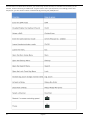
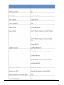
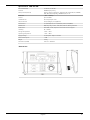
Owner's Manual
Digital Recording Systems
GKB-A0110M
GKB-A0110M.62.1.04.06.2012
© ASP AG
Keyboard with 3D joystick
Content:
4. Connection to a GRUNDIG DVR
7
1. Introduction
1
5. Connection to DVRs and Motordomes
8
2. Key Features of the Keyboard
2
6. Combined Connection (Recommended)
8
3. Important Safety Instructions
2
7. Camera Protocol Setup
8
4. Package Contents
2
8. DVR Protocol Setup
9
5. Installation
3
9. Keyboard Setup in a GRUNDIG DVR
9
1. Part Names and Functions
3
6. DVR Control
2. System Setup
6
7. Camera Control
3. Connection to a Motordome Camera
6
9
12
1. Introduction
Before product installation and operation, please become thoroughly familiar with this user manual and other
manuals referenced by this manual.
This user manual, the software and the hardware described here are protected by copyright law. With the
exception of copying for general use within fair use, copying and reprinting the user manual, either partially or in
entirety, or translating it into another language without the consent of ASP AG is strictly prohibited.
This specification may change without prior notice for improvement of product performance.
Product Warranty and Limits of Responsibility:
The manufacturer does not assume any responsibility concerning the sale of this product and does not delegate
any right to any third party to take any responsibility on its behalf. No warranty is offered for any attachments or
parts not supplied by the manufacturer. The product warranty does not cover cases of accidents, negligence,
alteration, misuse or abuse, for example:
- Malfunctions due to negligence by the user
- Deliberate disassembly and replacement by the user
- Connection of a power source other than a properly rated power source
- Malfunctions caused by natural disasters (fire, flood, tidal wave, etc.)
This product is not for exclusive use of crime prevention but also for assistance in cases of fire. We take no
responsibility for damage from any incident.
Caution:
This equipment underwent EMC registration and is suitable for business purposes. Distributors and users are
aware of this point.
Warning:
This is a class A product. In a domestic environment this product may cause radio interference, in which case the
user may be required to take adequate measures.
English
1
2. Key Features of the Keyboard
- Full control over GRUNDIG Recorders of the GRH or GDV series and GRUNDIG Motordome Cameras of the
GCA and GCH series
- Auto-protocol search function for easy installation of Motordome Cameras
- Multiple protocols implemented: Pelco-D, Pelco-P, Panasonic, Sony, Samsung, etc.
3. Important Safety Instructions
1. Do not place heavy objects on the top of the product.
2. This Product is for indoor use. It is not weatherproof. Please use the product considering its environmental
specifications (Temperature & Humidity). To clean the product, gently wipe the outside with a clean dry cloth.
3. This Product uses AC power of 110V ~ 240V. Be cautious not to cause electric damages to the product.
4. Be careful not to drop the product. Physical shocks may harm the product including the internal HDD. In
addition, be sure the product is secured after installation.
5. This Product is made of metal. Therefore you can hurt human beings if you throw it to them or hit it on them.
When installing the product, be cautious to locate it in safe places where children cannot reach it.
6. If the product does not operate properly, please contact the closest GRUNDIG distributor for after sales
service. Tampering or disassembling the product will cause expiration of the warranty.
7. Security surveillance laws may differ for each country. Therefore, please contact the local region first to avoid
any surveillance law violations.
8. Experience and technical skills are needed for the installation of this product as an improper installation may
cause fire, electric shocks, or defects. Any installation job should be performed by the vendor you purchased this
product from.
The content of this manual can differ according to firmware or software upgrading. The standard and appearance
of the products may be changed for the improvement of quality without prior notice.
4. Package Contents
These parts are included:
Keyboard, Power supply, Power cord, Cleaning towel, RS-232 connector, RS-485 connector, Owner’s manual
2
English
5. Installation
5.1. Part Names and Functions
Top View:
English
3
4
English
English
5
Rear View:
1) DC12V power port:Power supply connection
2) RS-485 communication port:Camera and/or DVR connection
3) RS-232 communication port:Firmware update or DVR connection
5.2. System Setup
The CCTV System Control Keyboard can connect and control various front-end/terminal equipment such as
Motordome Cameras, DVRs and Decoders via the RS-485 communication port. You can access the operation and
configuration functions of these by directly connecting them to the keyboard.
5.3. Connection to a Motordome Camera
Connect a Motordome Camera directly to the Keyboard by connecting the + and – of the RS-485 port with the
corresponding + and – ports of the Motordome Camera. Set both devices to the same protocol and baud rate.
6
English
5.4. Connection to a GRUNDIG DVR
Connect a GRUNDIG Recorder directly to the Keyboard by connecting the + and – of the RS-485 port with the
corresponding + and – ports of COM Port of the GRUNDIG DVR. Set the serial settings of the corresponding COM
port of the DVR to GKB-A0110M or WKC-100 (depending on the firmware).
The Keyboard is already configured under DVR mode. Motordome cameras that are connected to the DVR and
configured in the DVR can be controlled by the keyboard, too.
NOTE: You can also use a RS232 cable to control the DVR. Connect an appropriate cable to the connectors of the
keyboard and the DVR and configure the COM1 port of the DVR as described above.
English
7
5.5. Connection to DVRs and Motordome Cameras
It is also possible to connect several GRUNDIG DVRs and Motordome Cameras directly to the keyboard. There
will be no serial connection between the cameras and the DVRs, but the PTZ control will be more fluent.
5.6. Combined Connection (Recommended)
Another option to connect the Keyboard to a DVR and a Motordome Camera would be to connect them all directly
together, using a triangle connection. This will give you full control of the DVR and the Motordome, while adding
a slighty better performance under CAM mode using the PELCO-D protocol of the camera.
5.7. Camera Protocol Setup
If the Motordome Camera is connected to the DVR and not directly to the Keyboard, you do not need to setup the
protocol and baud rate. The Keyboard will use the GRUNDIG protocol to send the commands to the DVR, which
will forward them to the Motordome Camera.
8
English
If you have the Motordome Camera connected directly to the Keyboard, you will need to set up the protocol and
the baud rate of the Motordome Camera in the keyboard. To change the protocol of the CAM mode, you will need
to get administrator access to the keyboard first. Press [ID] and afterwards [ON], then enter the admin password
123456 and press [Enter] afterwards. Select the camera for which you want to change the protocol by pressing
the Camera ID and [Enter] afterwards and change the protocol by pressing the key [Protocol] until the used
protocol appears on the display, then press [Enter] to confirm. To adjust the baud rate, press the [Baudrate]
button until the used baud rate appears on the display. Press [Enter] to confirm the selected baudrate.
You can also use the [Search] button to automatically search for the protocol and baud rate. Follow the
instructions on the display to find the correct protocol and baud rate. Leave the administrator mode after you
have set up the protocol and baud rate by pressing [ID] and [Off] afterwards.
5.8. DVR Protocol Setup
Under DVR mode the keyboard is set automatically to the GRUNDIG proprietary DVR protocol that should work
straight away. If you need to change the protocol or baudrate of the DVR mode, just enter the administrator mode
(the procedure is similar to the one for CAM mode).
5.9. Keyboard Setup in a GRUNDIG DVR
The Keyboard needs to be configured in the Main Menu of the DVR under Device > Serial. It can be configured for
each Serial connection (Com1 (RS232), or Com2 and Com3 (RS485)). Just select the serial connection to which
the keyboard is attached to and change the protocol to WKC100 or GKB-A0110M (depending on the firmware
version). Under default settings the baud rate is set to 9600. If you have changed the baudrate of the keyboard
under DVR mode, please adjust the DVR correspondingly.
Picture: Default settings for the Keyboard in the DVR
6. DVR Control
The System Keyboard can take over all the functions on the front panel or the On-screen Menu of the DVR.
Therefore all the buttons that are named the same as a button on the front panel will execute the same
functionality. Please check the DVR manual for reference what these buttons do.
The Joystick will perform the Up, Down, Left & Right functionality of the direction keys and can also execute the
[Esc] and [Enter] button if you turn it counter- or clockwise.
To select a DVR, please enter the DVR mode by pressing the button [DVR]. Then select the ID of the DVR by
pressing [ID], then pressing the number and [Enter] in the end (in the table, ID+No+Enter). The ID of the DVR can
be changed in the system menu of the DVR under System> Utilitiy> Keyboard ID.
To select the Single Channel View, press the dedicated number of the channel and then press [Enter] (No+Enter,
in the table - for example, 3+Enter for Channel 3 or 1+2+Enter for channel 12).
English
9
If the Channel is a Motordome Camera, you will directly access the Pan, Tilt and Zoom functionality of the
camera, without switching to CAM mode. To get access to more functionalities, like loading presets and
sequences, you will need to switch to CAM mode by pressing the [CAM] button.
10
English
English
11
7. Camera Control
Under CAM mode you will be able to access more functions of the Motordome Camera depending of the protocol
that is used in the Motordome Camera. With GRUNDIG cameras and the PELCO-D protocol you can load Presets,
Sequences, Auto-Pans and Cruises. It is also possible to save Presets, Auto-Pans and Cruises. Of course you can
also access the OSD of the camera and do all the configuration of the Motordome Camera from remote.
If you switch from DVR mode to CAM mode, the Keyboard will set the ID of the CAM mode camera to the last
selected single channel view. If you want to change the ID of the camera, please press a number and [Enter]
afterwards (No+Enter, in the table - for example, 1+1+Enter to select the Camera with the ID 11). You can control
the PTZ function with the 3D Joystick by moving it left, right, up & down and turn the Joystick wheel counter- and
clockwise.
The following table explains how to call and save functions of the Motordome Camera connected to a GRUNDIG
DVR using the GRUNDIG Protocol.
12
English
English
13
Note: If you have the Motordome Camera connected directly to the Keyboard using the PELCO-D protocol, all of
the functions of the above table will work, only the functionalities in the table below are different.
14
English
Specifications GKB-A0110M
Serial Interface(s)
1x RS-232, 1x RS-485
Protocol
GRUNDIG proprietary
Multi protocol (camera)
Pelco-D, Pelco-P, Panasonic, Samsung, DM, SonyD70, VCL, MIKAMI,
CBC, B01, B02, SonyD70_R, GRUNDIG, VC, LILIN
Baud Rate
1,200 ~ 19,200bps
Control
Up to 99 DVRs
LCD Panel size
2x16 Gray Graphic LCD
Pan/Tilt Control
Pan (Left/Right), Tilt (Up/Down)
Lens Control
Iris (Close/Open), Focus (Near/Far), Zoom (Tele/Wide)
DVR Control
RW, Stop, Play, FF, Rec, PTZ, Menu, Search, Backup, Monitors
PTZ Control
Auto PAN, Preset, Sequence and Cruise Function Support
Humidity
20 ~ 70%RH
Storage Temperature
-40°C ~ +70°C
Operating Temperature
-10°C ~ +50°C
Supply Voltage
12 VDC power adaptor included
Power Consumption
1.5 W
Weight
2.5 kg
Dimensions (wxhxd)
299 x 94 x 188.5 mm
Dimensions
English
15
EC Declaration of Conformity
GKB-A0110M
Keyboard with 3D joystick
It is hereby certified that the products meet the standards in
the following relevant provisions:
EC EMC Directive 2004/108/EC
Low Voltage Directive 2006/95/EC
Applied harmonised standards and technical specifications:
EN 55022: 2003,
EN 61000-6-2: 2002, EN 61000-6-3: 2002,
EN 61000-4-2: 2001, EN 61000-4-3: 2003,
EN 61000-4-4: 2002, EN 61000-4-5: 2001,
EN 61000-4-6: 2001
ASP AG
Lüttringhauser Str. 9
42897 Remscheid
Germany
Remscheid, 04.06.2012
Ludwig Bergschneider
CEO
16
English