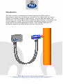
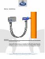
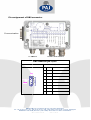
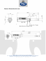
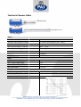
1
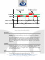
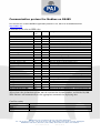
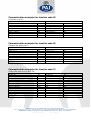
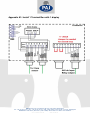
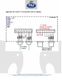
<
1%
%
!"
" #
$%&
33*4) 5 6 4 '
!"
76 4
% * --
+
" '
()*
!' ++' ,,,.%/
-0
76 4
#!76
8(
! 96
3(
!
(*:
%;!
1% .%/
2.%/
-0
(5
%
;=
6
=
%; >
=
$ =
? 1% . %
$%
=%
;
; %% 1; =
@;
% %
1
11
1 %
& 1
11
=A =%
% %
=A =% % %
1 % @&
=A =% % %
1 %
.%>@ &
=A =% % %
1 % @& % 1
=A =% % %
1 % @ & % 1 @ BB
=A =% % %
1 % @ & % 1 @ BB
( 11
=%
.
= ; C
*
!
" #$
! %&'( )
(
*
8(
=% %
;( ; 1 >
+
+ ,%
- ) .
+
+ ,%
- ) .
+
+ ,%
) .
+
+ ,%
) .
+
+ ,%
) .
+
+ ,%
) .
+
+ ,%
) .
+
+ ,%
) .
+
+0, +-1 (
+
+ ,
2
3+4
( 1.% >6 ; 1%
!"
" #
$%&
33*4) 5 6 4 '
!"
76 4
#!
/
/
/
/
/
/
/
/
" '
()*
!' ++' ,,,.%/
-0
76 4
#!76
8(
! 96
3(
!
(*:
+ %;!
0
1% .%/
2.%/
-0
(5
A
=%
> 1D6
4
A.
..>%
=
=
1%
% .
=A =% % %
%
A D6
4E
,%
7 %
& 7
7A> % =
% ; 1
F
A > 1=
;% D6
4
7 1 %
&%
=%
-A
%
,A=A1 %
,%
=
=%
1 % -A
1 %
&=
= A
.,
A A.
% = > 1- A
..
=%
% ;
,
A D6
4
%
A
1 %
&
!"
" #
$%&
33*4) 5 6 4 '
!"
76 4
" '
()*
!' ++' ,,,.%/
-0
76 4
#!76
8(
! 96
3(
!
(*:
%;!
1% .%/
2.%/
-0
(5
For your safety
The WIO400 (WIO) is designed as water in oil monitoring system, with a relay switchoff function and RS485 communication based on Modbus protocol.
Before use please read the user manual and carefully store it in a safe place. Install
and operate the device only after reading and comprehending the instruction manual,
and after you are familiar with the valid rules on work safety and accident prevention.
Please use the device only as specified. For this purpose please also note the values
in section “Technical data”.
During transport, storage and operation please adhere to the conditions listed in
“Technical data”.
IMPORTANT
Only qualified personnel may assemble start-up and maintain the unit when it is in a
zero voltage state. Only qualified electricians may work on electrical installations.
The connection and instruction manual contains information that enables the proper
and efficient use of the WIO monitoring system. PAJ Sensors A/S is not liable for
damage caused be improper use of this device. This manual is an integral part of the
basic knowledge necessary for proper use of the system.
Rights
PAJ Sensors A/S reserves the right to alter its products without prior notice.
Copying and using the instruction manual for other purposes is only allowed with the
acceptance from PAJ Sensors A/S.
PAJ Sensors A/S accepts no responsibility for possible errors and deficiencies in
brochures, catalogues and other printed material.
PAJ Sensors A/S guarantees correct function as well as fulfillment of the safety
requirements only when connections are made in accordance with instructions.
Safety observations
The comments about safety in this document will not discuss safety observations of
individual machine parts where safety devices (usually safety relays) are applied.
Here the respective instruction manuals will be referenced! This document merely
describes how to establish a WIO and how to start it up.
!"
" #
$%&
33*4) 5 6 4 '
!"
76 4
" '
()*
!' ++' ,,,.%/
-0
76 4
#!76
8(
! 96
3(
!
(*:
%;!
1% .%/
2.%/
-0
(5
WARNING
The monitoring system during machine operation cannot be guaranteed if the system
is connected incorrectly or not used as specified. This may lead to fatal injuries.
Interventions and changes to the WIO monitoring system are not permitted, unless
they are explicitly described in this user manual or be written from PAJ Sensors A/S.
The regional legal regulations and conditions of the liability insurance of the employer
must be maintained.
Area of application
The WIO monitoring system is usually used in engines were a WIO will monitor the
water content in lubrication oil, gear box oil, diesel oil, hydraulic oil or transformer oil.
The advantage of this monitoring system is the simple 4-20 mA interface and the two
relays indicating alarms, with digital readout.
Normally the WIO sensor is calibrated in Taro30 lubrication oil, if nothing else are
defined from customer.
Short description of the function
PAJ Sensors A/S has developed a water in oil (WIO) monitoring system. The
fundamental idea of the WIO system is to easily and continuously monitor the water
activity (aw) in oil. The output is converted into a standard 4-20 mA output.
The system also includes two relays indicating when too much water is present in the
oil. Default alarm values are set to 0,5 aw (high alarm) and 0,9 aw (high high alarm)
With the WIO-Software can HHA and HA level changes and there can be
continuously read out the actual (aw) or PPM of water in the oil.
WARNING
Do not use the sensor or relays to automatically enable/turn on or disable/shut down
engine. The decision to enable/turn on or disable/shut down an engine, based on the
sensor data, must be taken by proper trained crew personnel, not by the sensor
system.
!"
" #
$%&
33*4) 5 6 4 '
!"
76 4
" '
()*
!' ++' ,,,.%/
-0
76 4
#!76
8(
! 96
3(
!
(*:
! %;!
1% .%/
2.%/
-0
(5
Water activity (aw) provides the relative availability of water in oil where pure oil has
an activity of zero and oil saturated with distilled water has an activity of exactly one.
Under normal operation the WIO400 continuously supplies an output analogue signal
of 4 to 20 mA corresponding to 0.01 to 1.00 aw. Alarm indications with 0.03 aw
hysteresis via 2 relays are provided for each sensor. These data can also be read out
from the sensor on the RS485 Modbus communication line.
Default alarm values are 0,5 aw and 0,9 aw. Assumes these alarm values:
High alarm on at 0,50 aw (12 mA).
High alarm off at 0,47 aw (11,5 mA)
High high alarm on at 0,90 aw (18,4 mA).
High high alarm off at 0,87 aw (17,9 mA).
High high alarm will disable high alarm, thus only one alarm can be active.
Internal function failure will be indicated by activating both alarm relays at the same
time, or indicated as defined in the NAMUR NE43.
Internal failures includes:
•
•
•
Sensor reading out of range.
Sensor reading CRC error.
Unstable Sensor reading.
NAMUR NE43 is a German fault detection standard for 4-20mA analogue signals. It
allows the user to know if there is a fault within the instrument, by sending analogue
signal below 4mA and/or above 20mA. In accordance with NAMUR NE43, the failure
is indicated by:
•
Fault indicated by analogue output =<2,0 mA
!"
" #
$%&
33*4) 5 6 4 '
!"
76 4
" '
()*
!' ++' ,,,.%/
-0
76 4
#!76
8(
! 96
3(
!
(*:
%;!
1% .%/
2.%/
-0
(5
On the WIO Sensor there is a button for testing the alarm functions. By pushing the
Test button for 5 sec the high alarm relay turns on, and by pushing the Test button for
10 sec the high high alarm also turns on, after pushing the Test button for 15 sec
both relays turns off.
off After 20 sec pushing
ng the Test button then the Test button will be
ignored by the soft ware.
ware
Test Button
Un-pressed
Pressed = 5 sec
Mode
Normal operation
and no alarm
Test of high alarm
Pressed = 10 sec Test of high high alarm
Pressed = 15 sec Test of high alarm and
high high alarm
Pressed = 20 sec Normal operation
Test Button
Un-pressed
Pressed = 5 sec
Mode
Normal operation and
with high alarm active
Test of high alarm
Pressed = 10 sec Test of high high alarm
Pressed = 15 sec Test of high alarm and
high high alarm
Pressed = 20 sec Normal operation
!"
" #
$%&
33*4) 5 6 4 '
!"
76 4
Output Relay
Relay 1 closed
Relay 2 closed
Relay 1 open
Relay 2 closed
Relay 1 closed
Relay 2 open
Relay 1 closed
Relay 2 closed
Normal
Analogue Output
Normal
Output Relay
Relay 1 open
Relay 2 closed
Relay 1 open
Relay 2 closed
Relay 1 closed
Relay 2 open
Relay 1 closed
Relay 2 closed
Normal
Analogue Output
Normal
" '
()*
!' ++' ,,,.%/
-0
76 4
#!76
8(
! 96
3(
!
(*:
" %;!
Normal
Normal
Normal
Normal
Normal
Normal
Normal
Normal
1% .%/
2.%/
-0
(5
IMPORTANT
Only qualified personnel may assemble and maintain the unit. Only qualified
personnel may install the unit.
Screw in probe with ISO 228-1
228 G ¾” thread pressure-tight
tight directly in the center of the
oil pipe where the measurement is to take place. The threads should be sealed with
Loctite® 271. The sensor should
sh
be mounted with max. torque of 35 Nm. Connect
the cables from the WIO sensor to the Terminal box. Use a hexagon wrench size 30.
!"
" #
$%&
33*4) 5 6 4 '
!"
76 4
" '
()*
!' ++' ,,,.%/
-0
76 4
#!76
8(
! 96
3(
!
(*:
# %;!
1% .%/
2.%/
-0
(5
3,
%
% 1
IMPORTANT
Only qualified personnel may assemble start-up and maintain the terminal box(s)
when it is in a zero voltage state. Only qualified electricians may work on electrical
installations.
Install +24 VDC and GND into the terminal box and connect the 4-20 mA to an
external device if needed. Connect the relay to external device if needed.
If the terminal box has a (aw) or PPM display, there must be a short circuit between
terminals 11 and 12. This short circuit produces the needed closed loop for mA
measurement.
If the terminal box has a °C or °F display, there must be a short circuit between
terminals 9 and 10. This short circuit produces the needed closed loop for mA
measurement.
After installing the WIO-Software can PC and terminal box be connected through
DB9 connector.
Last connect the cables from the Terminal box to the sensor.
It is allowed (but not necessary) to connect screw terminal 10 and 12 “- 4-20 mA” to
screw terminal 14 “GND”, thus creating common ground for the output and the power.
Terminal boxes with display. Screw terminal pin 11 and 12 or screw terminal pin 9
and 10 can be connected to external equipment, but only in a closed loop for mA
measurement.
!"
" #
$%&
33*4) 5 6 4 '
!"
76 4
" '
()*
!' ++' ,,,.%/
-0
76 4
#!76
8(
! 96
3(
!
(*:
' %;!
1% .%/
2.%/
-0
(5
!"
"
A
#
>
=
=
(? ;
;A
1 %
&=
%= -
Contact-Number
Description
9
+4 – 20 mA positive analog output signal for indication of temperature in oil.
This option is not available for WIO200
10
-4 – 20 mA return analog signal for indication of temperature in oil.
This option is not available for WIO200
11
+4 – 20 mA positive analog output signal for indication of aw or PPM in oil.
12
-4 – 20 mA return analog signal for indication of aw or PPM in oil.
13
Power supply, 24VDC ±10% and with max. residual voltage ripple 10%
14
Power supply ground terminal contact
15
Relay contact for HH Alarm
16
Relay contact for HH Alarm
17
Relay contact for H Alarm
18
Relay contact for H Alarm
$ =
=
..
..
..
1
&
& +
&
A%
!"
" #
$%&
33*4) 5 6 4 '
1 %
!"
76 4
&. %
;
" '
()*
!' ++' ,,,.%/
-0
76 4
#!76
8(
! 96
3(
!
(*:
%;!
1% .%/
2.%/
-0
(5
#
( 11
$ %
=%
3,
%
% 1
DB9 connector pin layout
Illustration
!"
" #
$%&
33*4) 5 6 4 '
!"
76 4
Assignment
" '
()*
!' ++' ,,,.%/
-0
76 4
#!76
8(
! 96
3(
!
(*:
%;!
1% .%/
2.%/
-0
(5
Sensor dimensions in mm for WIO standard
1 G ¾” Thread
ISO 228-1
30mm Wrench max. torque 35 Nm
Sensor dimensions in mm for WIO Ball valve
!"
" #
$%&
33*4) 5 6 4 '
!"
76 4
" '
()*
!' ++' ,,,.%/
-0
76 4
#!76
8(
! 96
3(
!
(*:
+ %;!
1% .%/
2.%/
-0
(5
!
!"
" #
$%&
33*4) 5 6 4 '
!"
76 4
" '
()*
!' ++' ,,,.%/
-0
76 4
#!76
8(
! 96
3(
!
(*:
%;!
1% .%/
2.%/
-0
(5
&
$
WIO Standard
WIO Ball Valve
Output
Analogue output (galvanic isolated)
4 – 20 mA for %,
Analogue output (galvanic isolated)
4 – 20 mA for temperature (0°C – 100°C)
Max. Load (analogue output)
< 500
Measurement Range (4 – 20 mA)
0,01 – 1,00 %,
Accuracy (0,05-0,95 %,)
± 0,03 %,
Accuracy (outside 0,05-0,95 %,)
± 0,05 %,
Resolution
< 0,004 %,
Digital output
Communication RS485
Input
Supply nominal voltage
24V DC ± 10%
Max. residual voltage ripple
10%
Maximum Load current
58 mA + output load current
Max. Power input
< 2,4 VA
Relays
Contact arrangement
2 x Normally Closed (NC)
Rated voltage
60V
Rated current (40°C)
1A
Max. DC Load breaking capacity
!"
" #
$%&
33*4) 5 6 4 '
!"
76 4
" '
()*
!' ++' ,,,.%/
-0
76 4
#!76
8(
! 96
3(
!
(*:
%;!
1% .%/
2.%/
-0
(5
Relay 1
„High Alarm“
Relay 2
„High High Alarm“
Default High Alarm
0,50 %,
Default High High Alarm
0,90 %,
Socket specification
Connector design
1x male socket, 1x female socket
Connector locking system
Screw-locking
Wire gauge
0,25 mm
Contacts
8 Pol
Rated voltage
60V
Rated current (40°C)
1A
2
Cable specification
Cable design
Multipair overall screened cable PG9
Outlet diameter
9,9 mm
Voltage class
0,6/1kV
Wires
4x2 twisted pair
Wire gauge
0,75 mm
2
'
5
=%
%
Max. Oil temperature
90°C
Max. Oil pressure
10 Bar
8
@? !
Response times
Delay before valid data from start-up
< 30 s
Delay before valid data from installation (first use)
10 minutes
Device Failure Indication
Analogue output
< 2 mA
Manual test
Press sensor button for 5 seconds
High Alarm turns on for 5 seconds
Press sensor button for 10 seconds
High High Alarm turns also on for 5 seconds
Press sensor button for 15 seconds
Both Alarms turns off
Press sensor button for 20 seconds
Normal operating and test button ignored
Miscellaneous
Ambient Temperature, running / storage
0 - 90°C / -30 - +95°C
Relative humidity for running and storage
10% up to 95%, no condensation
Re calibration
Recommended with max 3 years interval
!"
" #
$%&
33*4) 5 6 4 '
!"
76 4
" '
()*
!' ++' ,,,.%/
-0
76 4
#!76
8(
! 96
3(
!
(*:
! %;!
1% .%/
2.%/
-0
(5
Warranty
2 years
Approvals
Germanischer Loyd
Enclosure
Weight for WIO standard
640 grams
Weight for WIO Ball valve
690 grams
Connection (mechanical)
ISO 228-1 G ¾ male and female thread.
Enclosure material
Stainless Steel
Protective type
IP66
!"
" #
$%&
33*4) 5 6 4 '
!"
76 4
" '
()*
!' ++' ,,,.%/
-0
76 4
#!76
8(
! 96
3(
!
(*:
%;!
1% .%/
2.%/
-0
(5
&
$
!
Output
Analogue output
See the specifications for sensor’s analogue output
Digital output
See the specifications for sensor’s digital output
Input
Supply nominal voltage
24V DC ± 10%
Max. residual voltage ripple
10%
Maximum Load current
20 mA + output load current
Max. Power input
< 0,6 VA
Relays
Contact arrangement
2 x Normally Closed (NC)
Rated voltage
250 VAC
Max. switching voltage
400VAC
Rated current
2A
Breaking capacity max.
1250VA
Enclosure
Weight
510 grams
Connection to sensor (mechanical)
2 x PG9 connectors (male + female) or gland PG *
Connection (mechanical)
2 x gland PG **
Enclosure material
Aluminum
Protective type
IP66
Warranty
2 years
G
GG
;
;
%
%
B E
3 '73
B E
3 '73
3
73
7
!F
7
!
3
F
FUNCTIONING
Terminal box shall be provided with 24vdc.
Terminal box supply 24vdc on to WIO sensor.
WIO sensor delivers mA, digital values and relay status to the terminal box.
!"
" #
$%&
33*4) 5 6 4 '
!"
76 4
" '
()*
!' ++' ,,,.%/
-0
76 4
#!76
8(
! 96
3(
!
(*:
"%;!
1% .%/
2.%/
-0
(5
&
$
$
!
Output
Analogue output
See the specifications for sensor’s analogue output
Digital output
See the specifications for sensor’s digital output
Input
Supply nominal voltage
24V DC ± 10%
Max. residual voltage ripple
10%
Maximum Load current
45 mA + output load current
Max. Power input
< 1,3 VA
Relays
Contact arrangement
2 x Normally Closed (NC)
Rated voltage
250 VAC
Max. switching voltage
400VAC
Rated current
2A
Breaking capacity max.
1250VA
Display version -
(
),%
%=
>; 1 7
7 *
Accuracy (0,05-0,95 %,)
± 0,03 %,
Resolution
<0,004 %,
Display version -
' )+, *
Accuracy (0,05-0,95 %,)
30%
Resolution
1 PPM
Enclosure
Weight
570 grams
Connection to sensor (mechanical)
2 x PG9 connectors (male + female) or gland PG *
Connection (mechanical)
2 x gland PG **
Enclosure material
Aluminum
Protective type
IP66
Warranty
2 years
G
GG
;
;
%
%
B E
3 '73
B E
3 '73
!"
" #
$%&
33*4) 5 6 4 '
3
73
!"
76 4
7
!F
7
!
3
F
" '
()*
!' ++' ,,,.%/
-0
76 4
#!76
8(
! 96
3(
!
(*:
#%;!
1% .%/
2.%/
-0
(5
FUNCTIONING
Terminal box shall be provided with 24vdc.
Terminal box supply 24vdc on to WIO sensor.
Terminal box measuring mA from the sensor, and convert it to %, or PPM value.
WIO sensor delivers mA, digital value and relay status to the terminal box.
IMPORTANT
The display is an indication of the water level in the oil. Display can be shipped as
PPM or aw.
Upon ordering a PPM display the customer must specify the water saturation point in
PPM of the used oil at the preferred working temperature of the oil. The saturation
point is typically between 3000-10000 PPM. Alternatively the customer can ship 10
liters of oil to PAJ Sensor A/S for inspection including specification of the working oil
temperature.
WARNING
All displays will show from positive values when operating properly. There will appear
a negative value during start-up, after 5 seconds the value will be in positive
measurement range. Otherwise, if a negative value is present the Terminal box might
have been installed incorrectly.
NOTE
There are three terms for the measurement of water in oil.
PPM is where the saturation point must be known at a given temperature.
%H20 and aw measures in principle the same, aw measures from 0,03 up to 1,00
moisture in the oil, and %H20 measures from 0,00 up to 1,00 moisture in the oil.
!"
" #
$%&
33*4) 5 6 4 '
!"
76 4
" '
()*
!' ++' ,,,.%/
-0
76 4
#!76
8(
! 96
3(
!
(*:
'%;!
1% .%/
2.%/
-0
(5
&
$
!
Output
Analogue output
See the specifications for sensor’s analogue output
Digital output
See the specifications for sensor’s digital output
Input
Supply nominal voltage
24V DC ± 10%
Max. residual voltage ripple
10%
Maximum Load current
33 mA + output load current
Max. Power input
< 1,0 VA
Relays
Contact arrangement
2 x Normally Closed (NC)
Rated voltage
250 VAC
Max. switching voltage
400VAC
Rated current
2A
Breaking capacity max.
1250VA
Buzzer
Oscillation frequency
3000±500 Hz
Sound pressure level
85db by open housing
Tone
pulsed
Button with LED
Blink frequency
2 Hz
Color
RED
Enclosure
Weight
530 grams
Connection to sensor (mechanical)
2 x PG9 connectors (male + female) or gland PG *
Connection (mechanical)
2 x gland PG **
Enclosure material
Aluminum
Protective type
IP66
Warranty
2 years
G
GG
;
;
%
%
B E
3 '73
B E
3 '73
!"
" #
$%&
33*4) 5 6 4 '
3
73
!"
76 4
7
!F
7
!
3
F
" '
()*
!' ++' ,,,.%/
-0
76 4
#!76
8(
! 96
3(
!
(*:
+ %;!
1% .%/
2.%/
-0
(5
FUNCTIONING
Terminal box shall be provided with 24vdc.
Terminal box supply 24vdc on to WIO sensor.
Terminal box indicate the relay status from the WIO sensor.
WIO sensor delivers mA, digtal values and relay status to the terminal box.
H-Alarm LED is for indication of the High Alarm relay state from the WIO sensor.
When the alarm condition is generated by the WIO sensor, then the High Alarm relay
is open and the H-Alarm LED flash red ON/OFF sequence to show the High Alarm
state, and the alarm signal buzzer will be switched ON.
HH-Alarm LED is for indication of the High High Alarm relay state from the WIO
sensor. When the alarm condition is generated by the WIO sensor, then the High
High Alarm relay is open and the HH-Alarm LED flash red ON/OFF sequence to
show the High High Alarm state, and the alarm signal buzzer will be switched ON.
The H-Alarm LED or HH-Alarm LED will stay in blinking mode until the H-Alarm or
HH-Alarm button is pressed, then the LED constantly turned on.
The alarm signal buzzer will stay on until the H-Alarm or HH-Alarm button is pressed.
Abstract representation of the H-Alarm and HH-Alarm button and LED function:
Figure 1: H-Alarm and HH-Alarm button function
!"
" #
$%&
33*4) 5 6 4 '
!"
76 4
" '
()*
!' ++' ,,,.%/
-0
76 4
#!76
8(
! 96
3(
!
(*:
+ %;!
1% .%/
2.%/
-0
(5
&
$
!
--
Output
Analogue output
See the specifications for sensor’s analogue output
Digital output
See the specifications for sensor’s digital output
Input
Supply nominal voltage
24V DC ± 10%
Max. residual voltage ripple
10%
Maximum Load current
58 mA + output load current
Max. Power input
< 1,7 VA
Relays
Contact arrangement
2 x Normally Closed (NC)
Rated voltage
250 VAC
Max. switching voltage
400VAC
Rated current
2A
Breaking capacity max.
1250VA
Display version -
(
),%
%=
>; 1 7
7 *
Accuracy (0,05-0,95 %,)
± 0,03 %,
Resolution
<0,004 %,
Display version -
' )+, *
Accuracy (0,05-0,95 %,)
30%
Resolution
1 PPM
Buzzer
Oscillation frequency
3000±500 Hz
Sound pressure level
85db by open housing
Tone
pulsed
Button with LED
Blink frequency
2 Hz
Color
RED
!"
" #
$%&
33*4) 5 6 4 '
!"
76 4
" '
()*
!' ++' ,,,.%/
-0
76 4
#!76
8(
! 96
3(
!
(*:
++%;!
1% .%/
2.%/
-0
(5
Enclosure
Weight
650 grams
Connection to sensor (mechanical)
2 x PG9 connectors (male + female) or gland PG *
Connection (mechanical)
2 x gland PG **
Enclosure material
Aluminum
Protective type
IP66
Warranty
2 years
G
GG
;
;
%
%
B E
3 '73
B E
3 '73
3
73
7
!F
7
!
3
F
FUNCTIONING
Terminal box shall be provided with 24vdc.
Terminal box supply 24vdc on to WIO sensor.
Terminal box measuring mA from the sensor, and convert it to %, or PPM value.
WIO sensor delivers mA, digital values and relay status to the terminal box.
H-Alarm LED is for indication of the High Alarm relay state from the WIO sensor.
When the alarm condition is generated by the WIO sensor, then the High Alarm relay
is open and the H-Alarm LED flash red ON/OFF sequence to show the High Alarm
state, and the alarm signal buzzer will be switched ON.
HH-Alarm LED is for indication of the High High Alarm relay state from the WIO
sensor. When the alarm condition is generated by the WIO sensor, then the High
High Alarm relay is open and the HH-Alarm LED flash red ON/OFF sequence to
show the High High Alarm state, and the alarm signal buzzer will be switched ON.
The H-Alarm LED or HH-Alarm LED will stay in blinking mode until the H-Alarm or
HH-Alarm button is pressed, then the LED constantly turned on.
The alarm signal buzzer will stay on until the H-Alarm or HH-Alarm button is pressed.
Abstract representation of the H-Alarm and HH-Alarm button and LED function:
!"
" #
$%&
33*4) 5 6 4 '
!"
76 4
" '
()*
!' ++' ,,,.%/
-0
76 4
#!76
8(
! 96
3(
!
(*:
+ %;!
1% .%/
2.%/
-0
(5
Figure 2: H-Alarm and HH-Alarm button function
IMPORTANT
The display is an indication of the water level in the oil. Display can be shipped as
PPM or aw.
Upon ordering a PPM display the customer must specify the water saturation point in
PPM of the used oil at the preferred working temperature of the oil. The saturation
point is typically between 3000-10000 PPM. Alternatively the customer can ship 10
liters of oil to PAJ Sensor A/S for inspection including specification of the working oil
temperature.
WARNING
All displays will show from positive values when operating properly. There will appear
a negative value during start-up, after 5 seconds the value will be in positive
measurement range. Otherwise, if a negative value is present the Terminal box might
have been installed incorrectly.
NOTE
There are three terms for the measurement of water in oil.
!"
" #
$%&
33*4) 5 6 4 '
!"
76 4
" '
()*
!' ++' ,,,.%/
-0
76 4
#!76
8(
! 96
3(
!
(*:
+ %;!
1% .%/
2.%/
-0
(5
PPM is where the saturation point must be known at a given temperature.
%H20 and aw measures in principle the same, aw measures from 0,03 up to 1,00
moisture in the oil, and %H20 measures from 0,00 up to 1,00 moisture in the oil.
!"
" #
$%&
33*4) 5 6 4 '
!"
76 4
" '
()*
!' ++' ,,,.%/
-0
76 4
#!76
8(
! 96
3(
!
(*:
+! %;!
1% .%/
2.%/
-0
(5
Output
Analogue output
See the specifications for sensor’s analogue output
Digital output
See the specifications for sensor’s digital output
Input
Supply nominal voltage
24V DC ± 10%
Max. residual voltage ripple
10%
Maximum Load current
83 mA + output load current
Max. Power input
< 2,4 VA
Relays
Contact arrangement
2 x Normally Closed (NC)
Rated voltage
250 VAC
Max. switching voltage
400VAC
Rated current
2A
Breaking capacity max.
1250VA
Display version -
(
),%
,%
%=
>; 1 7
7 *
Accuracy (0,05-0,95 %,)
± 0,03 %,
Resolution
<0,004 %,
Display version -
' )+, *
Accuracy (0,05-0,95 %,)
30%
Resolution
1 PPM
Display version -
"
Accuracy
± 3% rH
Resolution
20 ... 90% rH (max. Dew point = 50°C)
!"
" #
$%&
33*4) 5 6 4 '
!"
76 4
" '
()*
!' ++' ,,,.%/
-0
76 4
#!76
8(
! 96
3(
!
(*:
+ %;!
1% .%/
2.%/
-0
(5
Buzzer
Oscillation frequency
3000±500 Hz
Sound pressure level
85db by open housing
Tone
pulsed
Button with LED
Blink frequency
2 Hz
Color
RED
Enclosure
Weight
720 grams
Connection to sensor (mechanical)
2 x PG9 connectors (male + female) or gland PG *
Connection (mechanical)
2 x gland PG **
Enclosure material
Aluminum
Protective type
IP66
Warranty
G
GG
2 years
;
;
%
%
B E
3 '73
B E
3 '73
3
73
7
!F
7
!
FUNCTIONING
Terminal box shall be provided with 24vdc.
Terminal box supply 24vdc on to WIO sensor.
Terminal box measuring mA from the sensor, and convert it to %, or PPM value.
WIO sensor delivers mA, digital values and relay status to the terminal box.
H-Alarm LED is for indication of the High Alarm relay state from the WIO sensor.
When the alarm condition is generated by the WIO sensor, then the High Alarm relay
is open and the H-Alarm LED flash red ON/OFF sequence to show the High Alarm
state, and the alarm signal buzzer will be switched ON.
HH-Alarm LED is for indication of the High High Alarm relay state from the WIO
sensor. When the alarm condition is generated by the WIO sensor, then the High
High Alarm relay is open and the HH-Alarm LED flash red ON/OFF sequence to
show the High High Alarm state, and the alarm signal buzzer will be switched ON.
The H-Alarm LED or HH-Alarm LED will stay in blinking mode until the H-Alarm or
HH-Alarm button is pressed, then the LED constantly turned on.
The alarm signal buzzer will stay on until the H-Alarm or HH-Alarm button is pressed.
Abstract representation of the H-Alarm and HH-Alarm button and LED function:
!"
" #
$%&
33*4) 5 6 4 '
!"
76 4
" '
()*
!' ++' ,,,.%/
-0
76 4
#!76
8(
! 96
3(
!
(*:
+"%;!
1% .%/
2.%/
-0
(5
Figure 2: H-Alarm and HH-Alarm button function
IMPORTANT
The display is an indication of the water level in the oil. Display can be shipped as
PPM or aw.
Upon ordering a PPM display the customer must specify the water saturation point in
PPM of the used oil at the preferred working temperature of the oil. The saturation
point is typically between 3000-10000 PPM. Alternatively the customer can ship 10
liters of oil to PAJ Sensor A/S for inspection including specification of the working oil
temperature.
WARNING
All displays will show from positive values when operating properly. There will appear
a negative value during start-up, after 5 seconds the value will be in positive
measurement range. Otherwise, if a negative value is present the Terminal box might
have been installed incorrectly.
NOTE
There are three terms for the measurement of water in oil.
!"
" #
$%&
33*4) 5 6 4 '
!"
76 4
" '
()*
!' ++' ,,,.%/
-0
76 4
#!76
8(
! 96
3(
!
(*:
+#%;!
1% .%/
2.%/
-0
(5
PPM is where the saturation point must be known at a given temperature.
%H20 and aw measures in principle the same, aw measures from 0,03 up to 1,00
moisture in the oil, and %H20 measures from 0,00 up to 1,00 moisture in the oil.
!"
" #
$%&
33*4) 5 6 4 '
!"
76 4
" '
()*
!' ++' ,,,.%/
-0
76 4
#!76
8(
! 96
3(
!
(*:
+'%;!
1% .%/
2.%/
-0
(5
"
'
.
/0
PAJ Sensor have used the MODBUS application protocol V1.1b3, which can be downloaded from
http://modbus.org.
Command list all value are HEX value
Item
Address
descriptions
Read relay status of HA
Read relay status of HHA
Read factory reset bit status
Read termination resistor status
Function
code
01
01
01
01
26
27
2A
29
Relay is enabled = 1 => no alarm
Relay is enabled = 1 => no alarm
Data = 1 => WIO is ready for factory reset
Data = 1 => Resistor is omitted ( see RS485 guideline)
Read HA alarm level
Read HHA alarm level
Read WIO S/N
Read calibration date
Read WIO type
Read PPM max value
03
03
03
03
03
03
1E
20
04
31&32
23
2D
Data have to be recalculated to aW value for HA alarm
Data have to be recalculated to aW value for HHA alarm
S/N of connected WIO device
Date of calibration. Year month day
Data = 4 => WIO400
PPM saturations point at a given °C
Read °C
Read aW
Read mA output for aW
Read mA output for °C
Read current PPM value
Read °F
04
04
04
04
04
04
06
07
2C
2E
34
35
The measured temperature of the sensor
The measured moist in aW from the sensor
The mA output for aW from WIO sensor
The mA output for °C from WIO sensor
mA value converted into a PPM value
The measured temperature of the sensor
Set factory reset bit
Set termination resistor
05
05
2A
29
Make the Wio ready for factory reset
Activate the termination Resistor ( see RS485 guideline)
Complete factory reset
Change Modbus ID on WIO
06
06
08
24
Before complete factory reset, must factory reset bit = 1
Change the ID nr ( Valid data is 01 – FA ) from factory 01
Change HA alarm level
Change HHA alarm level
10
10
1E
20
aW must be calculated to HEX. Factory value is 0,50aW
aW must be calculated to HEX. Factory value is 0,90aW
Change Modbus ID on WIO
00
24
Change the ID nr ( Valid data is 01 – FA ) from factory 01
All read out value in function code 04, must be rewritten for decimal numbers, and divided by 100.
WIO-Software will automatically use the appropriate commands for displaying data.
Com Port setting
Baudrate
Data bits
Parity
Stop bits
9600
8
0 (none)
1
!"
" #
$%&
33*4) 5 6 4 '
!"
76 4
" '
()*
!' ++' ,,,.%/
-0
76 4
#!76
8(
! 96
3(
!
(*:
%;!
1% .%/
2.%/
-0
(5
Communication examples for function code 01
Read factory reset bit status
Request from user
Modbus ID
Function code
Starting address Hi
Starting address Lo (factory reset bit status)
Quantity of outputs Hi
Quantity of outputs Lo
CRC Hi
CRC Lo
01
01
00
2A
00
01
DC
02
Response from WIO
Modbus ID
Function code
Byte count
Output status
CRC
CRC
01
01
01
00
51
88
Communication examples for function code 03
Read WIO type
Request from user
Modbus ID
Function code
Starting address Hi
Starting address Lo (WIO type)
Quantity of outputs Hi
Quantity of outputs Lo
CRC Hi
CRC Lo
01
03
00
23
00
01
75
C0
Response from WIO400
Modbus ID
Function code
Byte count
Output status Hi
Output status Lo
CRC
CRC
01
03
02
00
03
F8
45
Communication examples for function code 04
Read measured temperature
Request from user
Modbus ID
Function code
Starting address Hi
Starting address Lo (Read °C)
Quantity of outputs Hi
Quantity of outputs Lo
CRC Hi
CRC Lo
01
04
00
06
00
01
D1
CB
Response from WIO (22,25°C)
Modbus ID
01
Function code
04
Byte count
02
Output status Hi
08
Output status Lo
B1
CRC
7E
CRC
84
08B1 is a HEX value, rewritten for decimal numbers is 2225, it must be divided by 100 and the
result is 22,25°C
All read out value in function code 04, must be rewritten for decimal numbers, and divided by 100.
!"
" #
$%&
33*4) 5 6 4 '
!"
76 4
" '
()*
!' ++' ,,,.%/
-0
76 4
#!76
8(
! 96
3(
!
(*:
%;!
1% .%/
2.%/
-0
(5
Communication examples for function code 05
Set factory reset bit
Request from user
Modbus ID
Function code
Starting address Hi
Starting address Lo (factory reset bit status)
Register Value Hi
Register Value Lo
CRC Hi
CRC Lo
01
05
00
2A
FF
00
AC
76
Response from WIO
Modbus ID
Function code
Starting address Hi
Starting address Lo
Output status Hi
Output status Lo
CRC
CRC
01
05
00
2A
FF
00
AC
76
Communication examples for function code 06
Complete the factory reset
Request from user
Modbus ID
Function code
Starting address Hi
Starting address Lo (factory reset complete)
Quantity of outputs Hi
Quantity of outputs Lo
CRC Hi
CRC Lo
01
06
00
08
00
01
C9
C8
Response from WIO
Modbus ID
Function code
Starting address Hi
Starting address Lo
Output status Hi
Output status Lo
CRC
CRC
Before complete factory reset, the factory reset bit must be set to 01
01
06
00
08
00
01
C9
C8
Communication examples for function code 10
Change HA alarm level to 0,55 aW
Request from user
Modbus ID
Function code
Starting address Hi
Starting address Lo (HA alarm level)
Quantity of outputs Hi
Quantity of outputs Lo
Byte count
Register Value Hi
Register Value Lo
Register Value Hi
Register Value Lo
CRC Hi
CRC Lo
!"
" #
$%&
33*4) 5 6 4 '
01
10
00
1E
00
02
04
CD
CC
0C
3F
C8
AC
!"
76 4
Response from WIO
Modbus ID
Function code
Starting address Hi
Starting address Lo
Output status Hi
Output status Lo
CRC
CRC
" '
()*
!' ++' ,,,.%/
-0
76 4
#!76
8(
! 96
3(
!
(*:
+%;!
01
10
00
1E
00
02
21
CE
1% .%/
2.%/
-0
(5
CRC Calculation
Use google, search for: on-line Modbus CRC calculation.
Put in the calculator (only HEX value) 0101002A0001.
The calculator can give you 2 result 02DC or DC02.
If the result is 02DC, then just put 02 behind DC, and the CRC result will be DC02.
If the result is DC02. Then you have the CRC value
Error codes
If you get a response back by a factor of 80 higher, as in the example shown, it is 3. digit
explanation of the error code.
Example 1.
Request from user to WIO: 01 01 00 25 00 01 EC 01
Response from WIO: 01 81 02 C1 91
81 says that there is an error in the transmitted function code 01 message.
02 says that it is the wrong address.
Example 2.
Request from user to WIO: 01 10 00 1D 00 02 04 00 00 10 3F 7E EA
Response from WIO: 01 90 02 CD C1
90 says that there is an error in the transmitted function code 10 message.
02 says that it is the wrong address.
Example 3.
Request from user to WIO: 01 05 00 28 00 FF 0D 82
Response from WIO: 01 85 03 02 91
85 says that there is an error in the transmitted function code 05 message.
03 says that it is the wrong data for this address.
There are 4 possible error digit.
01 function code not supported
02 wrong address
03 to many output registers are selected or wrong input of data
04 error in reading the selected register
!"
" #
$%&
33*4) 5 6 4 '
!"
76 4
" '
()*
!' ++' ,,,.%/
-0
76 4
#!76
8(
! 96
3(
!
(*:
%;!
1% .%/
2.%/
-0
(5
Table for aW to HEX value
aW value
HEX value
aW value
HEX value
WIO-Software
Connect the USB-Stick to the PC and wait for windows has installed driver for this USB-Stick on
PC. Then select Setup and wait until everything is installed. After install is completed, restart the
PC and start WIO-Software, WIO-Software will even find the current communication port.
!"
" #
$%&
33*4) 5 6 4 '
!"
76 4
" '
()*
!' ++' ,,,.%/
-0
76 4
#!76
8(
! 96
3(
!
(*:
%;!
1% .%/
2.%/
-0
(5
RS485 Guidelines
As its name implies, a twisted pair is simply a pair of wires of equal length and twisted together.
Using a twisted-pair wire reduces two major sources of problems for users of high-speed long
distance networks. It reduces noise on the transmitted and received signals.
An important condition for communication over long distance is that the transmission lines are
properly terminated with a termination resistor (RT) of 120 . Which is typically is the
characteristic impedance of a twisted-pair wire. If the resistance is omitted, the signals sent on the
wire, will be reflected where the cable physically ends and hike back on the cord. Here they will
interfere with subsequent transmitted signals. For long cable runs, this can cause data errors,
especially at high speeds.
There is a built-in termination resistor in the WIO, which can be connected with function code 05.
The maximum number of unit loads allowed one twisted pair, assuming a properly terminated cable
with a characteristic impedance of 120 or more, is 32 unit.
!"
" #
$%&
33*4) 5 6 4 '
!"
76 4
" '
()*
!' ++' ,,,.%/
-0
76 4
#!76
8(
! 96
3(
!
(*:
! %;!
1% .%/
2.%/
-0
(5
1"2$
"
PAJ Group, Grundtvigs Allé 163, DK-6400 Sønderborg, Denmark
Manufactory
Declare under our sole responsibility that the product:
unit identification:
product classification:
WIO200 – WIO300 – WIO400 – WIO500
Water In Oil measuring instrument
is a safety tested component according to EC Guideline:
2004/108/EC Electromagnetic compatibility
2006/95/EC Low voltage directive
to which this declaration relates is in conformity with the following standard(s) or other normative documents(s):
IEC 61326-1:2006-11-03, EN 61010-1:2001, EN 60529 Edition 2.1 2001-02,
IEC 60068-1:1988, IEC 60068-2-2:2007, IEC 60068-2-1:2007, IEC 60068-2-30:2005,
IEC 60068-2-6:2007, IEC 61000-4-16:1998-01, IEC 61000-4-6:2007, IEC 61000-43:2006,
IEC 61000-4-5:2005, IEC 61000-4-2:2001, IEC 61000-4-4:2004
The described product corresponds to the following European Directives:
2004/108/EC Electromagnetic compatibility
2006/95/EC Low voltage directive
Consistency of a production sample device with the marked product in accordance with the Directives No:
2004/108/EC Electromagnetic compatibility
2006/95/EC Low voltage directive
Germanischer Lloyd AG Head Office
Deputy Head of Department
Automation, Navigation and Communication (MC-EA)
Vorsetzen 35
D-20459 Hamburg/Germany
Notified agency/Address:
75 956 – 09 HH
2009-11-30
Certification number
Date of issue
The marked product is consistent with the examined production sample device.
Technical documentation:
Poul Jessen
______________________________________________________________________
Grundtvigs Allé 163 • DK-6400 Sønderborg • Tel: +45 74 43 71 81 • E-Mail: [email protected]
Sønderborg, 15.04.2011
Poul Jessen, Managing Director
Date of issue
Name and signature
!"
" #
$%&
33*4) 5 6 4 '
!"
76 4
" '
()*
!' ++' ,,,.%/
-0
76 4
#!76
8(
! 96
3(
!
(*:
%;!
1% .%/
2.%/
-0
(5
!"
" #
$%&
33*4) 5 6 4 '
!"
76 4
" '
()*
!' ++' ,,,.%/
-0
76 4
#!76
8(
! 96
3(
!
(*:
"%;!
1% .%/
2.%/
-0
(5
!"
" #
$%&
33*4) 5 6 4 '
!"
76 4
" '
()*
!' ++' ,,,.%/
-0
76 4
#!76
8(
! 96
3(
!
(*:
#%;!
1% .%/
2.%/
-0
(5
Appendix A1: Install 1 Terminal Box with 1 display
!"
" #
$%&
33*4) 5 6 4 '
!"
76 4
" '
()*
!' ++' ,,,.%/
-0
76 4
#!76
8(
! 96
3(
!
(*:
'%;!
1% .%/
2.%/
-0
(5
Appendix A2: Install 1 Terminal Box with no display
!"
" #
$%&
33*4) 5 6 4 '
!"
76 4
" '
()*
!' ++' ,,,.%/
-0
76 4
#!76
8(
! 96
3(
!
(*:
%;!
1% .%/
2.%/
-0
(5
Appendix A3: Install 2 Terminal Boxes with 3 display
!"
" #
$%&
33*4) 5 6 4 '
!"
76 4
" '
()*
!' ++' ,,,.%/
-0
76 4
#!76
8(
! 96
3(
!
(*:
%;!
1% .%/
2.%/
-0
(5
Appendix A4: Install 2 Terminal Boxes with 1 display
!"
" #
$%&
33*4) 5 6 4 '
!"
76 4
" '
()*
!' ++' ,,,.%/
-0
76 4
#!76
8(
! 96
3(
!
(*:
+%;!
1% .%/
2.%/
-0
(5
Appendix A5: Install 2 Terminal Boxes with 2 display
!"
" #
$%&
33*4) 5 6 4 '
!"
76 4
" '
()*
!' ++' ,,,.%/
-0
76 4
#!76
8(
! 96
3(
!
(*:
%;!
1% .%/
2.%/
-0
(5
Appendix A6: Install 3 Terminal Boxes with 4 display
!"
" #
$%&
33*4) 5 6 4 '
!"
76 4
" '
()*
!' ++' ,,,.%/
-0
76 4
#!76
8(
! 96
3(
!
(*:
%;!
1% .%/
2.%/
-0
(5
Appendix A7: Install 3 Terminal Boxes with 3 display
!"
" #
$%&
33*4) 5 6 4 '
!"
76 4
" '
()*
!' ++' ,,,.%/
-0
76 4
#!76
8(
! 96
3(
!
(*:
! %;!
1% .%/
2.%/
-0
(5
Appendix A8: Install 3 Terminal Boxes with 2 display
!"
" #
$%&
33*4) 5 6 4 '
!"
76 4
" '
()*
!' ++' ,,,.%/
-0
76 4
#!76
8(
! 96
3(
!
(*:
%;!
1% .%/
2.%/
-0
(5
Appendix A9: CABLE Specification
!"
" #
$%&
33*4) 5 6 4 '
!"
76 4
" '
()*
!' ++' ,,,.%/
-0
76 4
#!76
8(
! 96
3(
!
(*:
"%;!
1% .%/
2.%/
-0
(5
Appendix A10: Error / failure FAQ
Failure type
Description
Possible reasons
PPM display
failure
Display shows only negative numbers
1. Sensor is not connected.
2. The error caused by missing jumper in
terminal box pin 11 and pin 12. See
Appendix A1
3. Check that the jumper is properly
installed, it is seen that the jumper has been
installed but the jumper had no proper
connection
4. The wires are reversed in terminal box pin
7 and pin 8 lower part. After changing and
there is no change in the display, then the
fault is either 1, 2 or 3.
%, display
failure
Dispay shows only negative numbers
1. Sensor is not connected.
2. The error caused by missing jumper in
terminal box pin 11 and pin 12. See
Appendix A1
3. Check that the jumper is properly
installed, it is seen that the jumper has been
installed but the jumper had no proper
connection
4. The wires are reversed in terminal box pin
7 and pin 8 lower part. After changing and
there is no change in the display, then the
fault is either 1, 2 or 3.
Dead display
Display indicate nothing
!"
" #
$%&
33*4) 5 6 4 '
!"
76 4
Maybe is 24V dc supply interrupted to the
display. There shall be 24V dc at this
connector.
" '
()*
!' ++' ,,,.%/
-0
76 4
#!76
8(
! 96
3(
!
(*:
#%;!
1% .%/
2.%/
-0
(5
Relay
Always alarm ON or always OFF
1. Most often the cause is wrong connection
or understanding of NC.
Sensor
How to check the mA output from sensor?
Remove jumper in pin 11 and pin 12. In
order to ensure that there can be measured
mA must pin 11 and pin 12 must be screwed.
Remember to set the measuring instrument
in dc mA and connect test leads correctly in
the measuring instrument. Sensor is alright
when measuring a value between 4 and 20
mA. Is the result about 2 mA then there is an
internal sensor error, so the sensor must be
sent for repair. Is the result 0 mA, tjek if the
sensor get 24 Vdc power.
Dip Switch
Are the dip switch still correctly?
%,
Dip Switch
PPM
Are the dip switch still correctly?
!"
" #
$%&
33*4) 5 6 4 '
!"
76 4
" '
()*
!' ++' ,,,.%/
-0
76 4
#!76
8(
! 96
3(
!
(*:
'%;!
1% .%/
2.%/
-0
(5
3:
%
E !F "
"#
C% .%/
2.%/
-0
!"
" #
$%&
33*4) 5 6 4 '
!"
76 4
" '
()*
!' ++' ,,,.%/
-0
76 4
#!76
8(
! 96
3(
!
(*:
! %;!
1% .%/
2.%/
-0
(5