1
V7N Drive with DeviceNet
Technical Manual
TM
Models: CIMR-V7NU
Document Number: TM.V7N.01
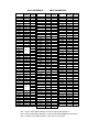
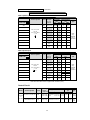
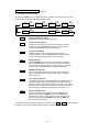
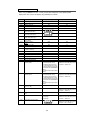
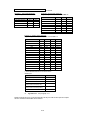
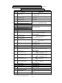
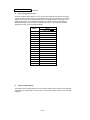
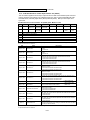
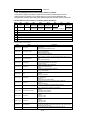
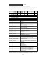
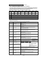
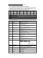
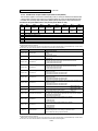
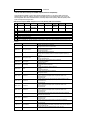
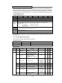
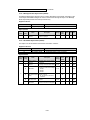
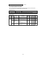
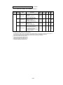
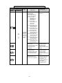
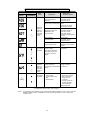
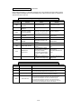
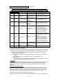
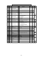
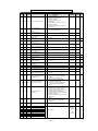
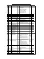
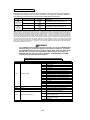
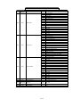
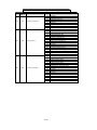
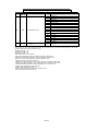
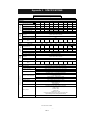
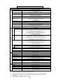
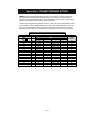
QUICK REFERENCE – – DRIVE PARAMETERS
PARAMETERS FACTORY USER
SETTING SETTING
n001
1
n002
0
n003
3
n004
9
n005
0
n006
0
n007
0
n008
0
n009
0
n010
0
n011
60
n012
230/460
n013
60
n014
(Note 2)
n015
(Note 2)
n016
(Note 2)
n017
(Note 2)
n018
0
n019
n020
10.0
n021
n022
n023
0
n024
6.00
n025
0.00
n026
0.00
n027
0.00
n028
0.00
n029
0.00
n030
0.00
n031
0.00
n032
6.00
n033
100
n034
0
n035
0
n036
(Note 1)
n037
0
n038
8
n039
0
n040
0
n041
n042
10.0
n043
n044
n050
1 (1)
n051
2 (2)
n052
3 (0)
n053
5 (5)
n054
6 (6)
n055
7 (7)
n056
10 (10)
n057
2
n058
1
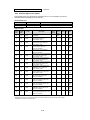
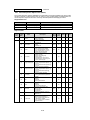
PARAMETERS FACTORY USER
SETTING SETTING
n059
0
n064
0
n068
100
n069
0
n070
0.10
n071
100
n072
0
n073
0.10
n077
0
n078
0
n079
0
n080
3
n081
0
n082
0
n083
0.00
n084
0.00
n085
0.00
n086
0.00
n087(3)
0
n088(3)
0
n089
50
n090
0.0
n091
0.0
n092
0
n093
170
n094
160
n095
0.00
n096
0
n097
0
n098
160
n099
0.1
n100
0
n101
2.0
n102
150
n103
1.0
n104
(Note 2)
n105
(Note 1)
n106
(Note 1)
n107
(Note 1)
n108
(Note 1)
n109
150
n110
(Note 1)
n111
(Note 2)
n112
(Note 2)
n113
0
n115
0
n116
0
n117
0
n118
10
n119
0.1
n120
0.00
n121
0.00
n122
0.00
n123
0.00
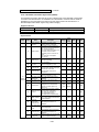
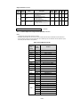
PARAMETERS FACTORY USER
SETTING SETTING
n124
0.00
n125
0.00
n126
0.00
n127
0.00
n128
0
n129
1.00
n130
1.0
n131
1.0
n132
0.00
n133
0
n134
100
n135
0.0
n136
0
n137
0
n138
1.0
n139
0
n140
(Note 1)
n141
50
n142
12
n143
1 (24 ms)
n144
0%
n145
0.5%
n146
0.2%
n148
71
n149
21
n150
63
n151
0
n152
0.2
n153
0
n154
0
n155
0
n156
0
n157
0
n158
(Note 1)
n159
120
n160
16
n161
10
n162
5 (20 ms)
n163
1.0
n164
0
n166
0
n167
0
n168
0
n169
0.0
n170
0
n173
83 (0.083)
n174
25 (100 ms)
n175
0
n176
rdy
n177
0
n178
N/A
n179
0011
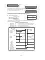
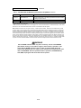
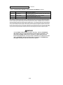
Note 1: Factory setting differs depending on the Drive capacity. See Appendix 3-1.
Note 2: Factory setting differs depending on control method selected (n002). See Appendix 3-1.
Note 3: Available only in CIMR-V7NU25P5, 27P5, 45P5, and 47P5 drives.
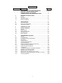
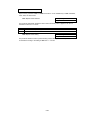
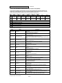
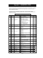
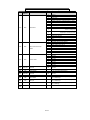
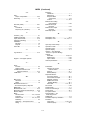
CONTENTS
PARAGRAPH
SUBJECT
PAGE
QUICK REFERENCE FOR DRIVE PARAMETERS ....................Inside Cover
WARNINGS, CAUTIONS, INSTRUCTIONS ......................................... iii
SIMPLIFIED STARTUP PROCEDURE.................................................. v
CURRENT RATINGS AND HORSEPOWER RANGE .......................... ix
1
1.1
1.2
1.3
1.4
RECEIVING AND INSTALLATION .....................................................
General ................................................................................................
Receiving .............................................................................................
Physical Installation .............................................................................
Electrical Installation ............................................................................
1-1
1-1
1-1
1-1
1-6
2
2.1
2.2
2.3
INITIAL START-UP ..............................................................................
Pre-Power Checks ...............................................................................
Open Loop Vector Startup ...................................................................
V/f Startup Procedure ..........................................................................
2-1
2-1
2-2
2-6
3
OPERATION AT LOAD ....................................................................... 3-1
4
4.1
4.2
4.3
4.4
4.5
DIGITAL OPERATOR ..........................................................................
General ................................................................................................
Digital Operator ....................................................................................
Status Indicator LEDs ..........................................................................
DeviceNet LEDs....................................................................................
Monitor Displays ..................................................................................
5
5.1
5.2
5.3
5.4
5.5
5.6
5.7
5.8
5.9
5.10
5.11
5.12
5.13
5.14
5.15
5.16
5.17
PROGRAMMABLE FEATURES ......................................................... 5-1
General ................................................................................................ 5-1
Accel/Decel Time ................................................................................. 5-2
Accel/Decel: S-Curve Characteristics .................................................. 5-3
Auto-Restart ......................................................................................... 5-4
Carrier Frequency ................................................................................ 5-4
Critical Frequency Rejection ................................................................ 5-6
DC Injection Braking ............................................................................ 5-7
Frequency Reference Upper and Lower Limits .................................... 5-8
Frequency Reference Retention .......................................................... 5-8
Frequency Reference Selection .......................................................... 5-9
Jog Reference .................................................................................... 5-12
Local/Remote Reference and Sequence Selection ............................ 5-13
Miscellaneous Protective Functions ................................................... 5-15
Momentary Power Loss Ride-Thru ..................................................... 5-15
Multi-Function Input Terminals (Term. S1-S4) .................................... 5-16
Multi-Function Output Terminals (Term. MA, MC, P1, P2, PC) .......... 5-22
Overtorque Detection ......................................................................... 5-25
-i-
4-1
4-1
4-1
4-3
4-3
4-5
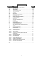
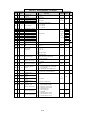
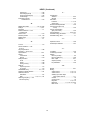
CONTENTS – Continued
PARAGRAPH
PAGE
SUBJECT
5.18
5.19
5.20
5.21
5.22
5.23
5.24
5.25
5.26
5.27
5.28
5.29
5.30
5.31
5.32
Reset Codes: 2-Wire, 3-Wire Initialization .......................................... 5-27
Slip Compensation ............................................................................. 5-28
Stall Prevention ................................................................................... 5-29
Stopping Method ................................................................................ 5-31
Thermal Overload Protection .............................................................. 5-32
Torque Compensation ......................................................................... 5-33
V/f Pattern ........................................................................................... 5-34
PID Control ......................................................................................... 5-36
Copy Function ..................................................................................... 5-40
Digital Operator Display Selection ...................................................... 5-46
Energy Saving Control ........................................................................ 5-47
Multi-Function Analog Input Selection ................................................ 5-49
Frequency Reference Loss Detection ................................................. 5-51
Undertorque Detection ....................................................................... 5-51
Elapsed Timer ......................................................................................5-53
6
6.1
6.2
6.3
6.4
6.5
DEVICENET COMMUNICATIONS....................................................... 6-1
Introduction ........................................................................................... 6-1
DeviceNet Set-up.................................................................................. 6-1
DeviceNet Parameters .......................................................................... 6-7
DeviceNet Polled I/O Messaging ......................................................... 6-11
DeviceNet Explicit Messaging ..............................................................6-25
7
7.1
7.2
7.3
7.4
FAULT DIAGNOSIS AND CORRECTIVE ACTIONS............................7-1
General..................................................................................................7-1
Displaying Fault Sequence....................................................................7-8
DeviceNet Faults ...................................................................................7-9
DeviceNet Troubleshooting...................................................................7-11
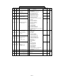
Appendix 1
PARAMETER LISTING ....................................................................... A1-1
Appendix 2
SPECIFICATIONS .............................................................................. A2-1
Appendix 3
CAPACITY AND CONTROL METHOD RELATED
PARAMETERS ................................................................................... A3-1
Appendix 4
PERIPHERAL DEVICES .................................................................... A4-1
Appendix 5
DRIVE DIMENSIONS ......................................................................... A5-1
Appendix 6
DYNAMIC BRAKING OPTION .......................................................... A6-1
Appendix 7
NAMEPLATE INFORMATION ........................................................... A7-1
Appendix 8
REMOVE/INSTALL DRIVE FACE PLATES ....................................... A8-1
Appendix 9
DEVICENET CONFIGURATION ........................................................ A9-1
Index
.............................................................................................................. I-1
- ii -
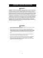
WARNINGS, CAUTIONS, INSTRUCTIONS
WARNING
YASKAWA manufactures component parts that can be used in a wide variety of industrial
applications. The selection and application of YASKAWA products remain the responsibility of
the equipment designer or end user. YASKAWA accepts no responsibility for the way its
products are incorporated into the final system design. Under no circumstances should any
YASKAWA product be incorporated into any product or design as the exclusive or sole safety
control. Without exception, all controls should be designed to detect faults dynamically and
fail safely under all circumstances. All products designed to incorporate a component part
manufactured by YASKAWA must be supplied to the end user with appropriate warnings and
instructions as to that part’s safe use and operation. Any warnings provided by YASKAWA
must be promptly provided to the end user. YASKAWA offers an express warranty only as to
the quality of its products in conforming to standards and specifications published in the
YASKAWA manual. NO OTHER WARRANTY, EXPRESS OR IMPLIED, IS OFFERED.
YASKAWA assumes no liability for any personal injury, property damage, losses, or claims
arising from misapplication of its products.
WARNING
• Do not connect or disconnect wiring while the power is on. Do not remove covers or
touch circuit boards while the power is on.
• Before servicing, disconnect all power to the equipment. The internal capacitor
remains charged even after the power supply is turned OFF. Status indicator LEDs
and Digital Operator display will be extinguished when the DC bus voltage is below
50 VDC. To prevent electric shock, wait at least 5 minutes after all indicators are
OFF.
• Do not perform a withstand voltage test on any part of the unit. This equipment
uses sensitive devices and may be damaged by high voltage.
• The drive is not suitable for circuits capable of delivering more than 18,000 RMS
symmetrical amperes at 250V maximum or 480V maximum. Install adequate
branch short circuit protection. Refer to Appendix 4. Failure to do so may result in
equipment damage and/or personal injury.
- iii -
CAUTION
The Drive leaves the factory with parameters initialized for 2-Wire control (when
using external Run/Stop signals). Before using the initialization function of constant
n001, know your control wiring configuration:
10 = Factory 2-Wire Control Initialization (Maintained RUN Contact)
11 = Factory 3-Wire Control Initialization (Momentary START/STOP Contact)
Entering either Initialization code resets all parameters to factory settings, and
automatically returns parameter n001 setting to “ 1 ”. If the Drive is connected for
3-Wire control and this parameter is set to “ 10 ” (2-Wire Control Initialization), the
motor may run in reverse direction WITHOUT A RUN COMMAND APPLIED.
Equipment damage or personal injury may result.
Parameter n012 must be set to proper motor voltage.
Always ground the Drive using the ground terminal provided.
Never connect main circuit output terminals T1 (U), T2 (V) & T3 (W) to AC main
circuit power supply.
When programmed for auto-restart ( n082 = “ 1 ” thru “ 10 ”), the motor may restart
unexpectedly — personal injury may result
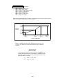
For Enclosed wall-mounted type (NEMA type 1)
When mounting units in an enclosure, remove the top, bottom and terminal covers. Install
a cooling fan or some other means to maintain the air entering the enclosure below 113°F
(45°C).
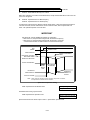
IMPORTANT
• Wiring should be performed only by qualified personnel.
• Verify that the rated voltage of the drive matches the voltage of the incoming power.
• Some drawings in this manual are shown with the protective covers and shields removed, in order to
describe detail with more clarity. Make sure all covers and shields are replaced before operating this
product.
• This manual may be modified when necessary because of product improvement, modification, or
changes in specifications.
• YASKAWA is not responsible for any modification of the product made by the user, doing so will void
the warranty.
- iv -
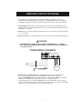
SIMPLIFIED STARTUP PROCEDURE
This procedure is a simplified step by step guide to installing, programming, and using
the Yaskawa V7N (hereafter referred to as the Drive). It highlights several common installation
configurations. Detailed information on all drive features can be found in this Technical Manual.
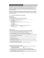
❏ Check Nameplate - Be certain your input voltage source, motor and drive nameplates are all
marked either 230V or 460V. Other voltages can be used, but require additional programming; see
paragraph 5.27, V/f pattern.
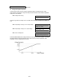
❏ Mount drive - on a vertical surface with adequate space for air circulation (4.7" above and below,
1.2" on each side).
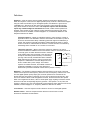
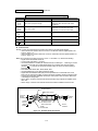
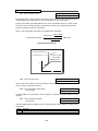
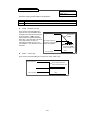
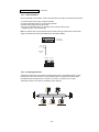
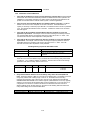
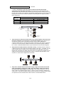
❏ Remove front cover - fit conduit to bottom plate, and connect power and ground wires as shown.
CAUTION
BE CERTAIN YOU CONNECT INPUT POWER TO TERMINALS L1, L2, AND L3
ONLY, OR SERIOUS DAMAGE WILL RESULT. CONNECT MOTOR TO TERMINALS
T1, T2, AND T3 ONLY.
POWER WIRING SCHEMATIC
–
+1
+2
R/L1 S/L2 T/L3
Note:
Exact terminal configuration
may vary with drive rating
B1
B2
U/T1 V/T2 W/T3
3 PHASE
INPUT
POWER
MOTOR
WIRE TO
EARTH GROUND
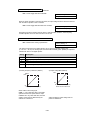
❏ Replace cover and apply input power – digital operator shows “0.00”; The FREF LED
is on and the RUN LED is flashing. Press the DSPL key until the LO/RE LED is on.
Press the UP ARROW button until the display shows “Lo,” then press the DSPL button until the
FREF LED is on. Rotate the potentiometer on the front of the digital operator
until the display shows “6.00.” Press the RUN button and note the direction of motor rotation. If
rotation is incorrect, remove power, wait for the display lights to go out, then switch wires between
terminals T1 and T2. Replace the front cover and apply input power.
-v-
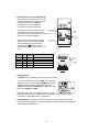
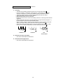
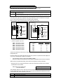
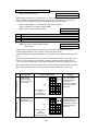
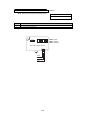
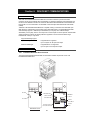
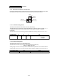
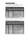
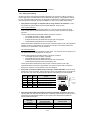
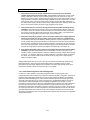
❏ DeviceNet and Control Terminal Wiring –
Remove power and wait for all LEDs to go
out before making DeviceNet and control
terminal connections. Use standard
DeviceNet thin or thick cable when
connecting to DeviceNet terminals.
RUN
Remove the front cover and connect the
DeviceNet communication wires on the
quick-disconnect screw terminal on the drive
(Section 6.2.3 Cable Installation).
SW1 Baud Rate
ALARM
PNP/NPN
Switch
SW4 LSD Addr.
23
1 4
0
5
9 8 76
SW3 MSD Addr.
2
1 34
0
5
9876
2
1 34
0
9 8 76
S1 S2 S3 S4 SC
P1 P2 PC
Control wiring should be sized 16 to 20
AWG. Control wiring should be shielded,
with the shield wire connected to the
ground terminal
, which is located
towards the left side of the aluminum heat
sink.
E
Control
Terminal Block
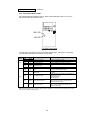
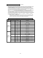
Quick-Disconnect
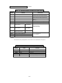
DeviceNet Terminal
Terminal
Color
Name
Wiring
Color
Content
Black
V-
Black
Communication power supply GND
Blue
CAN_L
Blue
Communication data low side
-
Shield
Bare
Shield wire
White
CAN_H
White
Communication data high side
Red
V+
Red
Without Front Cover
0.2in
(5.5mm)
Top View
Black Blue
W hite Red
DeviceNet
Cable
Communication power supply DC+24V
Side View
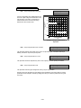
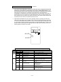
❏ Digital Operator
The DSPL button cycles through all of the quick start LEDs.
To access a parameter, press the DSPL button until the
PRGM LED is on. Use the UP and DOWN keys until the
desired parameter number is displayed, then press
ENTER. Use the UP and DOWN keys to adjust the value
then press ENTER then DSPL.
FREF
FOUT
F/R
IOUT
MNTR
LO/RE PRGM
DSPL
RUN
DATA
ENTER
STOP
RESET
MIN
MAX
Before the drive will accept a RUN command, one of the
following LEDs must be on: FREF, FOUT, IOUT, MNTR, or F/R. For more specific
information on the digital operator, see Section 4.
❏ Control Method – This section assumes that the drive will be left in the volts per
hertz (V/f) control method. For a further explanation of control method or to change the
control method, see Section 2.1.
- vi -
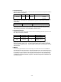
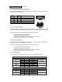
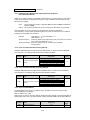
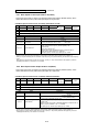
❏ DeviceNet Settings
Using the rotary switch SW1 (RATE) on the drive, set communication baud rate (Section 2.6 Baud
Rate and Address Configuration).
S1 Switch Setting
0
1
2
Baud Rate
125 kbps
250 kbps
500 kbps
3-9
Parameter n152:
0: 125kbps
1: 250kbps
2: 500kbps
Using the rotary switch SW3 (MSD) and SW4 (LSD), set the DeviceNet MAC ID. Be sure to verify
that no devices on the network have duplicate MAC ID’s (Section 2.6 Baud Rate and Address
Configuration).
S3 + S4 Switch Setting
Address or MAC ID
0 - 63
MAC ID = (S3 x 10) + S4
64 - 99
Parameter n150: Setting Range: 0 to 63
Reassemble the front cover and power up the V7N. Verify that the MS LED is lit green and NS
LED is flashing green (Section 2.8 DeviceNet Status Indication LED’s)
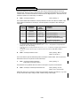
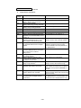
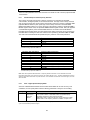
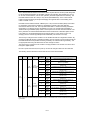
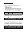
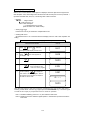
❏ DeviceNet Parameters
Verify the drive’s run/stop and frequency reference to be controlled by DeviceNet. (Section 2.10.2
Run / Stop and Frequency Selection)
Parameter
n003
n004
Display Text
Run Source
Option PCB
Reference Source
Option PCB
Default Value
3
9
Description
Sets the start/stop
to come from DeviceNet.
Sets the frequency
reference to come from
DeviceNet.
Note: When the above parameters are set and DeviceNet communication to the drive has not
begun, the operator will flash “CAL”. This alarm indicates that the drive is waiting for DeviceNet
communication to operate the drive. Once DeviceNet communication to the drive begins, the “CAL”
alarm will cease.
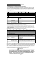
❏ EDS File
Download the proper EDS file for the corresponding V7N model number from the CD-ROM that
came with the V7N drive, from www.odva.org in the “Downloads” area, or from www.drives.com in
the “Our Products” - “Literature Library” - “Software Downloads” area. Each V7N drive capacity has
its own EDS file, so it is important to select the EDS file that matches the drive capacity (Section
2.9 EDS File). Install the EDS file in the configuration tool software, such as DeviceNet Manager
or RSNetworx from Rockwell Software. (Appendix 9 DeviceNet Configuration for RSNetWorx and
DeviceNet Manager)
- vii -
Definitions
Sequence – refers to how the drive is started, stopped, and told which direction to run.
When the sequence comes from the digital operator (local), the drive is started and stopped
using the “RUN” and “STOP” keys on the digital operator, and direction is given via the
“FWD/REV” key. Sequence can also come from the drive’s control terminals (remote)
using either two-wire or three-wire control. The sequence inputs to the drive do NOT
require any outside voltages to activate them. Instead, contact closures (either from
switches, relay contacts or open collector circuits) activate the sequence inputs. Other
sequence sources are available; consult Paragraph 5.13, Local/Remote Reference and
Sequence Selection for details.
Two-wire sequence – utilizes a “maintained” switch or relay contact. It is used on
applications where it is desirable to have the drive restart on restoration of power. It
should not be used where safety of attending personnel might be threatened by a
restart. This method is generally restricted to unattended fans & pumps, or where
another controller is entrusted with the decision to restart. Direction is controlled by
maintaining either a forward run or a reverse run command.
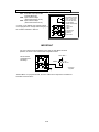
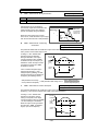
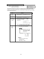
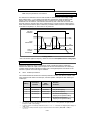
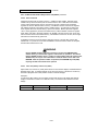
Three-wire sequence – utilizes “momentary” buttons or switches. This control
scheme emulates the traditional 3-wire motor starter control. A momentary closure of
a normally open run switch latches the drive in the RUN
Start
mode (STOP switch must be closed or the drive will not
S1
START
accept the momentary RUN command). A momentary
Stop
opening of the normally closed STOP switch unlatches
S2
STOP
RUN mode bringing the drive to a stop. The three-wire
sequence is used where it would be dangerous for the
SC
drive to restart after a power outage. This method
requires an intentional restart, as the RUN command is
3-Wire Sequence
unlatched immediately on loss of power. Direction is
determined by another maintained contact closure (closed = reverse).
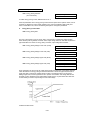
Reference – The frequency reference tells the drive how fast to run the motor. There are
several source options for the frequency reference. First, the frequency reference can come
from the digital operator (local). Simply put, the motor speed can be entered into the
keypad. Second, the frequency reference can come from an analog signal (remote), such
as 0 to 10 Volts DC. When 0 Volts is applied to the drive, the drive will run at zero speed.
When 10V is applied to the drive, it will run at full speed. Apply anything in between and the
drive will run at that corresponding frequency (2.5VDC = 25% speed = 15 Hz). Third, the
frequency reference can come from DeviceNet communications. Other reference sources are
available; consult Paragraph 5.11, Frequency Reference Selection for details.
Local Control – when the sequence and/or reference comes from the digital operator.
Remote Control – when the sequence and/or reference comes from the control
terminals or DeviceNet communications.
- viii -
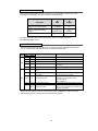
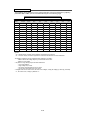
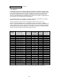
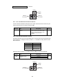
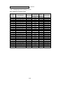
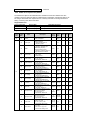
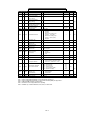
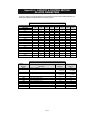
Current Ratings & Horsepower Range
Rated
Input Voltage
230V
460V
Current
Rating [A]
0.8
1.6
3.0
5.0
8.0
11.0
17.5
25.0
33.0
1.2
1.8
3.4
4.8
8.6
14.8
18.0
Nominal
Horsepower
1/8
1/4
1/2
3/4 & 1
2
3
5
7.5
10
1/2
3/4
1&2
3
5
7.5 & 10
10
Model Number
CIMR-V7NU
20P1
20P2
20P4
20P7
21P5
22P2
23P7
25P5
27P5
40P2
40P4
40P7
41P5
43P7
45P5
47P5
WARNING
Do not touch circuit components until main input power has been turned
OFF. Status indicator LEDs and Digital Operator display will be extinguished
when the DC bus voltage is below 50 VDC. Wait 5 additional minutes.
Do not connect or disconnect wires and connectors while the main input
power is turned on.
CAUTION
The Drive leaves the factory with parameters initialized for 2-Wire control
(when using external Run/Stop signals). Before using the initialization
function of constant n001, know your control wiring configuration:
10 = Factory 2-Wire Control Initialization (Maintained RUN Contact)
11 = Factory 3-Wire Control Initialization (Momentary START/STOP
Contact)
Entering either Initialization code resets all parameters to factory settings,
and automatically returns parameter n001 setting to “ 1 ”. If the Drive is
connected for 3-Wire control and this parameter is set to “ 10 ” (2-Wire
Control Initialization), the motor may run in reverse direction WITHOUT A
RUN COMMAND APPLIED. Equipment damage or personal injury may
result.
- ix -
-x-
Section 1. RECEIVING AND INSTALLATION
1.1 GENERAL
This document pertains to the V7N ac drive. This manual reflects the Software Version 0011 for
models CIMR-V7▫▫▫0P1 through V7▫▫▫4P0 and Software Version 0100 for models CIMR-V7▫▫▫5P5
and V7▫▫▫7P5. In this document, the word “drive”, “ac drive”, and “inverter” may be used
interchangeably. The V7N is a general purpose sine-coded pulse width modulated AC motor drive
with embedded DeviceNet communications. It generates an adjustable voltage/frequency three
phase output for complete speed control of most conventional squirrel cage induction motors.
Automatic stall prevention and voltage boost prevent nuisance tripping during load or line side
transient conditions. The Drive will not induce any voltage line notching distortion back to the utility
line, and it maintains a displacement power factor of not less than 0.98 throughout its speed range.
When properly installed, operated and maintained, the Drive will provide a lifetime of service. It is
mandatory that the person who operates, inspects, or maintains this equipment thoroughly read and
understand this manual before proceeding.
Information in this manual covers both the Drive functionality and DeviceNet communications. It
also contains basic information for the operator control station. For detailed operation of other units
in the drive system, refer to their respective manuals.
1.2 RECEIVING
The Drive is thoroughly tested at the factory. After unpacking, verify the part numbers on the
nameplate with the purchase order (invoice). Any damages or shortages evident when the
equipment is received must be reported immediately to the commercial carrier who transported the
equipment. Assistance, if required, is available from your sales representative.
CAUTION
Do not install a drive that is damaged or missing parts.
If the drive will be stored after receiving, keep it in its original packaging and store according to
storage temperature specifications in Appendix 2.
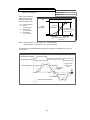
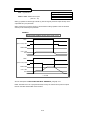
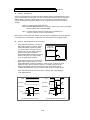
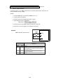
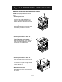
1.3 PHYSICAL INSTALLATION
Location of the Drive is important to achieve proper performance and normal operating life. The unit
should be installed in an area where it will be protected from:
• Extreme cold and heat. Use only within the ambient temperature range (for open chassis
type): 14 to 122°F (-10 to +50°C)
• Rain, moisture
• Oil sprays, splashes
• Salt spray
• Direct sunlight. (Avoid using outdoors)
• Corrosive gases (e.g. sulfurized gas) or liquids
• Dust or metallic particles in the air
• Physical shock, vibration
• Magnetic noise (Example: welding machines, power devices, etc.)
• High humidity
• Radioactive substances
• Combustibles: thinner, solvents, etc.
When preparing to mount the Drive, lift it by its base, never by the front cover. For effective cooling,
as well as proper maintenance, the Drive must be installed on a flat, non-flammable vertical surface
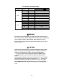
(wall or panel) using four mounting screws. There MUST be a MINIMUM 3.9 in. clearance above
and below the Drive to allow air flow over the heat sink fins. A minimum 1.2 in. clearance is required
on each side of the Drive.
1-1
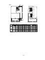
1.3 PHYSICAL INSTALLATION
Continued
AIR
3.94 in.
(100mm)
50mm
30mm
30mm
AIR
50mm
3.94 in.
(100mm)
1. To use 5.5/5.7 kw (7.5/10 Hp) Drives as open chassis, remove both top and bottom covers.
2. The clearances required at top/bottom and both sides are common in open chassis type
(IP00) and enclosed wall-mounted type (IP20).
3. For the external dimensions and mounting dimensions, refer to the “DIMENSIONS” section
of Appendix 5.
4. Allowable intake air temperature to the Drive:
Open chassis type:
-10°C to +50°C
Enclosed wall-mounted type: -10°C to +40°C
5. Allow sufficient space for the sections at the upper and lower parts marked with * in order to
permit the flow of intake/exhaust air to/from the Drive.
1-2
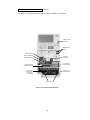
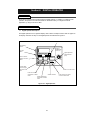
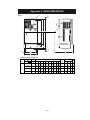
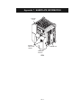
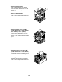
1.3 PHYSICAL INSTALLATION
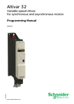
Continued
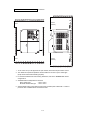
For details on removing the front panels and accessing the terminals, see Appendix 8.
Digital Operator
Speed Pot
Status Indicator
LEDs
SW1 Baud Rate
SW4 LSD Address
S2 Digital
Input Type
SW4 MSD Address
Control Circuit
Terminal Block
Quick Disconnect
DeviceNet Terminal
Main Circuit
Terminal Block
Shorting Bar
(Remove when
DC Reactor
is installed)
Ground Terminal
Figure 1-1a. Component Identification
1-3
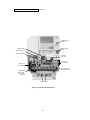
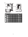
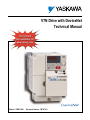
1.3 PHYSICAL INSTALLATION
Continued
Digital Operator
Speed Pot
Status Indicator
LEDs
SW1 Baud Rate
SW4 LSD Address
SW4 MSD Address
S2 Digital
Input Type
Control Circuit
Terminal Block
Main Circuit
Terminal Block
Quick Disconnect
DeviceNet Terminal
Shorting Bar
(Remove when
DC Reactor
is installed)
Ground Terminal
Figure 1-1b. Component Identification
1-4
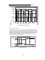
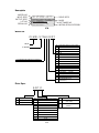
Continued
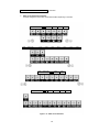
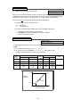
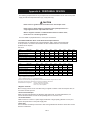
1.3 PHYSICAL INSTALLATION
I.
Main Circuit Terminal Arrangement
Terminal arrangement of the main circuit terminal differs depending on the drive.
Model
Model
CIMR-V7NU
CIMR-V7NU
21P5
Model
Model
20P1
20P2
22P2
40P2
CIMR-V7NU
CIMR-V7NU
25P5
20P4
40P4
20P7
40P7
23P7
43P7
27P5
45P5
Figure 1-1c. Main Circuit Terminals
1-5
41P5
47P5
42P2
1.4 ELECTRICAL INSTALLATION
The Drive leaves the factory with all parameters set for 2-Wire external reference control. Figure 1-5
must be used for all external connections.
To use the Drive in a 3-Wire application, drive parameters n001, n003, and n004 must be
reprogrammed, using the Digital Operator. Figure 1-6 must then be used for all external connections.
A. Main Circuit Input /Output Wiring
Complete wire interconnections according to Table 1-2, Figure 1-5 thru Figure 1-7. Be sure to
observe the following:
• Use 600V vinyl-sheathed wire or equivalent. Wire size and type should be determined by local
electrical codes.
• Avoid routing power wiring near equipment sensitive to electrical noise.
• Avoid running input and output wiring in the same conduit.
• NEVER connect AC main power to output terminals T1(U), T2(V), and T3(W).
• NEVER allow wire leads to contact metal surfaces. Short-circuit may result.
• NEVER connect power factor correction capacitors to the drive output. Consult Yaskawa when
connecting noise filters to the drive output.
• WIRE SIZING MUST BE SUITABLE FOR CLASS I CIRCUITS.
• When connecting motor to drive’s output terminals, include a separate ground wire. Attach ground
wire solidly to motor frame and to drive’s ground terminal
.
• When using armored or shielded cable for connection between drive and motor, solidly connect
armor or shield to motor frame, and to drive’s ground terminal
.
• Motor lead length should NOT EXCEED 164 feet (50 meters), and motor wiring should be run in a
separate conduit from the power wiring. If lead length must exceed this distance, reduce carrier
frequency (see paragraph 5.8) and consult factory for proper installation procedures.
• Use UL listed closed loop connectors or CSA certified ring connectors sized for the selected wire
gauge. Install connectors using the correct crimp tool recommended by the connector manufacturer.
1-6
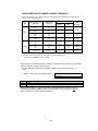
1.4 ELECTRICAL INSTALLATION
Continued
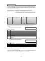
Table 1-1. Wire and Terminal Screw Sizes
230V 3-phase Input
Model
Terminal Symbol
Screw
CIMR-V7NU
20P1
Tightening
Torque
lb • in
(N • m)
7.1 to 8.88
(0.8 to 1.0)
7.1 to 8.88
M3.5
(0.8 to 1.0)
7.1 to 8.88
M3.5
(0.8 to 1.0)
7.1 to 8.88
M3.5
(0.8 to 1.0)
M4 10.65 to 13.31
(1.2 to 1.5)
M4 10.65 to 13.31
(1.2 to 1.5)
M4 10.65 to 13.31
(1.2 to 1.5)
22.19
M5
(2.5)
22.19
M5
(2.5)
M3.5
20P2
R/L1, S/L2, T/L3
B1, B2
U/T1, V/T2, W/T3
-, +1,+2
20P4
20P7
21P5
22P2
23P7
25P5
27P5
Wire
Applicable
Recommended
size
size
mm2 AWG
mm2 AWG
0.75 to 2 18 to
14
0.75 to 2 18 to
14
0.75 to 2 18 to
10
0.75 to 2 18 to
14
2 to 5.5 14 to
10
2 to 5.5 14 to
10
2 to 5.5 14 to
10
2
14
2
14
2
14
2
14
2
14
3.5
12
5.5
10
5.5 to 8 10 to 8
8
8
5.5 to 8 10 to 8
8
8
Type
600V
vinylsheathed
wire or
equivalent
460V 3-phase Input
Model
Terminal Symbol
Screw
CIMR-V7NU
40P2
M4
40P4
40P7
41P5
M4
R/L1, S/L2, T/L3
B1, B2
U/T1, V/T2, W/T3
-, +1,+2
42P2
x1
M4
M4
M4
43P7
M4
45P5
M4
47P5
M5
Tightening
Torque
lb • in
(N • m)
10.65 to 13.31
(1.2 to 1.5)
10.65 to 13.31
(1.2 to 1.5)
10.65 to 13.31
(1.2 to 1.5)
10.65 to 13.31
(1.2 to 1.5)
10.65 to 13.31
(1.2 to 1.5)
10.65 to 13.31
(1.2 to 1.5)
12.43
(1.4)
22.19
(2.5)
Wire
Applicable
Recommended
size
size
mm2 AWG
mm2 AWG
14 to
10
2 to 5.5 14 to
10
2 to 5.5 14 to
10
2 to 5.5 14 to
10
2 to 5.5 14 to
10
2 to 5.5 14 to
10
3.5 to 5.5 12 to
10
5.5 to 8 12 to
10
2 to 5.5
2
14
2
14
2
14
2
14
2
14
2
3.5 x 1
14
12 x 1
5.5
10
5.5
10
Type
600V
vinylsheathed
wire or
equivalent
Note: The wire size is set for copper wires at 160°F (75°C)
Control Circuit
Model
Common
to
all models
Terminal Symbol
Screw
S1 to S4, P1, P2, SC, PC
M2
DeviceNet Connector
M3
Tightening
Torque
lb • in (N • m)
Wire
Applicable size
mm2
AWG
1.94 to 2.21 twisted wire 0.5 to 0.75 20 to 18
(0.22 to 0.25) single
0.5 to 1.25 20 to 16
4.44 to 5.33
(0.5 to 0.6)
1-7
twisted wire 0.2 to 2.5
24 to 12
Recommended
size
Type
mm2 AWG
0.75
18
0.32/.2 22/24
Shielded
wire or
equivalent
DeviceNet
Thin
Cable
Continued
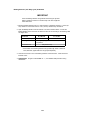
1.4 ELECTRICAL INSTALLATION
Table 1-2. Main Circuit Terminal Functions and Voltages
TERMINAL
FUNCTION
VOLTAGE / SIGNAL LEVEL
L1 (R)
L2 (S)
L3 (T)
Main circuit input power supply
230V Drive: 200 / 208 / 220 / 230V at 50/60 Hz
460V Drive: 380 / 400 / 440 / 460 / 480V
at 50/60 Hz
T1 (U)
T2 (V)
T3 (W)
Main circuit output
230V Drive: 0 - 200 / 208 / 220 / 230V
460V Drive: 0 - 400 / 440 / 460 / 480V
B1
B2
For connection of braking resistor (option)
+1
+2
DC Reactor terminals
–
DC Bus terminals (+1 & –)
Ground terminal (100 ohms or less)
––––
B. Control Circuit
All basic control circuit (signal) interconnections are shown in the appropriate diagram:
• Interconnections for external two-wire control in combination with the Digital Operator are
shown in Figure 1-5.
• Interconnections for external three-wire control in combination with the Digital Operator are
shown in Figure 1-6.
Make wire connections according to Figures 1-5 thru 1-7 and Table 1-3; observe the following:
• Signal Leads: Terminals S1-S4 & SC.
• Control Leads: Terminals P1, P2 & PC.
• Use twisted shielded or twisted-pair shielded wire (20-16 AWG [0.5 – 1.25mm2]) for control
and signal circuit leads. The shield sheath MUST be connected at the drive end ONLY
(terminal
). The other end should be dressed neatly and left unconnected (floating).
See Figure 1-2.
• DeviceNet Leads: Black, Blue, Shield, White, Red.
• Use DeviceNet thick or thin cable specified by ODVA.
• Signal leads and feedback leads (PG) must be separated from control leads main circuit
leads, and any other power cables, to prevent erroneous operation caused by electrical noise.
• Lead length should NOT EXCEED 164 feet (50 meters). Wire sizes should be determined
considering the voltage drop.
• All AC relays, contactors and solenoids should have RC surge supressors installed across
their coils.
• All DC relays, contactors and solenoids should have diodes installed across their coils.
SHIELD SHEATH
OUTER JACKET
TO DRIVE
SIGNAL
TERMINALS
TO SHIELD
SHEATH
TERMINAL
(TERM.
)
TO
EXTERNAL
CIRCUIT
WRAP BOTH ENDS
OF SHEATH WITH
INSULATING TAPE
CRIMP
CONNECTION
Figure 1-2. Shielded Sheath Termination
1-8
DO NOT
CONNECT
Continued
1.4 ELECTRICAL INSTALLATION
C. Grounding
• The drive must be solidly grounded using the main circuit ground terminal
.
• If Drive is installed in a cabinet with other equipment, ground leads for all equipment
should be connected to a common low-impedance ground point within the cabinet.
• The supply neutral should be connected to the ground point within the cabinet.
• Select appropriate ground wire size from Table 1-1.
• Make all ground wires as short as practical.
• NEVER ground the drive in common with welding machines, or other high power electrical
equipment.
• Where several drives are used, ground each directly to the ground point (see Figure 1-1).
DO NOT FORM A LOOP WITH THE GROUND LEADS.
• When connecting a motor to the drive’s output terminals, include a separate ground wire.
Attach ground wire solidly to motor frame and to drive’s ground terminal
.
• When using armored or shielded cable for connection between drive and motor, solidly
connect armor or shield to motor frame, and to the drive’s ground terminal
.
•
•
CORRECT
•
•
•
•
CORRECT
D. DeviceNet Connector and Cabling
• See Section 6 DeviceNet Communications.
E. DeviceNet Terminating Resistors
• See Section 6 DeviceNet Communications.
1-9
•
•
•
•
NOT
ACCEPTABLE
Continued
1.4 ELECTRICAL INSTALLATION
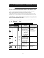
Table 1-3. Terminal Functions and Signals of Control Circuit
TERMINAL
FUNCTION
DESCRIPTION*
S1
Multi-Function-Input 1
Factory setting is " Forward Run/Stop " (1).
(Forward run when closed, stop when open)
S2
Multi-Function-Input 2
Factory setting is " Reverse Run/Stop " (1).
(Reverse Run when closed, stop when open)
S3
Multi-Function-Input 3
Factory setting is " External Fault (NO contact)
input " (1)
S4
Multi-Function-Input 4
Factory setting is " Fault Reset " (1)
SC
Sequence common for terminals S1-S4.
Common terminal for sequence inputs
P1
Multi-Function Open
Collector Output 1
Factory setting is
" Drive Running "
P2
Multi-Function Open
Collector Output 2
Factory setting is
" Speed Agree "
PC
Multi-Function Open
Collector Output common
0V
Photocoupler output:
48 VDC; 50 mA or less.
CN2 V
Frequency reference voltage input
0 to +10 / 100% (20K Ω)
CN2 I
Frequency reference current input
4 to 20 mA (250 Ω)
CN2 C
Frequency reference input common
0V
NOTES:
1.
These inputs have factory settings based on 2-wire reset. For 3-wire reset definitions, see Figure 1-6.
Table 1-4. Terminal Functions and Signals of DeviceNet
TERMINAL
BLACK
NAME
FUNCTION
V-
DeviceNet power supply ground
BLUE
CAN_L
DeviceNet data low
GREEN
Shield
Shield wire
WHITE
CAN_H
DeviceNet data high
V+
DeviceNet power supply +24VDC
RED
1-10
Continued
1.4 ELECTRICAL INSTALLATION
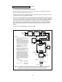
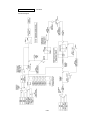
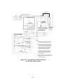
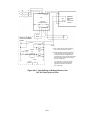
D. Auxiliary Input and Output Power Option Devices
A disconnect device (circuit breaker, contactor, disconnect switch, etc.) should NOT be used as a
means of starting and stopping the drive or motor.
A disconnect device can be installed for emergency stop purposes, but when that disconnect device
is opened, there may be loss of electrical braking.
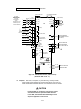
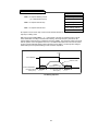
Figure 1-3 is a factory guideline for proper wiring practices and relative locations within the electrical
path from the line to the load. It does not imply what devices are needed for a particular application,
nor does it show what devices were shipped with a particular order. Therefore, disregard those items
in the diagram which are not being used in your installation. However, it is recommended that an
input or DC reactor be used with all Drive ratings when wired to a source of 600 kVA or greater.
Mount all optional power devices close to the drive, and keep electrical connections as short as
possible.
DO NOT run input and output wiring in the same conduit.
ISOLATION
TRANSFORMER
CUSTOMER’S
3fl A.C. LINE
POWER
SUPPLY
INPUT
RFI FILTER
L3
H3
X3
C1(L3)
L2
H2
X2
B1(L2) I
L1
H1
X1
A1(L1) E
INPUT
REACTOR
(L3)C2
L
N
L
O (L2)B2
A
D (L1)A2
C1
C2
B1
B2
A1
A2
(G)
EARTH GROUND
SEE NOTE 2
NOTES
1.
Connect drive ground terminal or panel to
earth ground. Always use low impedance
paths and connections.
2.
Mount input and output RFI filters physically
as close to the drive as possible (on the same
panel, if possible). Filters should have a solid
connection from filter case or ground terminal
to drive panel or ground terminal (conduit with
good bare metal to bare metal connections
may serve as the path). If multiple input or
output RFI filters are used, they must be
wired in parallel.
3.
Shield conductors with metallic conduit.
4.
Connect output conduit in a manner that
allows it to act as an unbroken shield from the
drive panel to the motor casing.
5.
RF noise filter (different from RFI filter) part
no. 05P00325-0023 is a delta wye capacitor
network which is wired in parallel with the
drive input terminals. On the smaller drives
with die cast chassis, it must be mounted
externally. On the larger drives with sheet
metal chassis, it may be mounted inside the
area where the input power wiring enters the
drive. On units equipped with bypass, it may
be wired to the primary side of the circuit
breaker and mounted to the bypass panel or
sidewall.
6.
RF NOISE
FILTER
SEE NOTE 5
SEE NOTE 3
EARTH GROUND
SEE NOTE 2
Input
Output
Ckt Brkr L1, L2, L3
T1, T2, T3
Unwired side of
Overload relay
L11 L21 L31
DC
REACTOR
+ 1
SEE NOTE 6
+ 2
OUTPUT
T1
T2
T3
EARTH GROUND
SEE NOTE 1
SEE NOTES 3, 4
1
OUTPUT
RFI FILTER
2
3
IN
OUT
4
5
6
A1
B1
C1
A2
B2
C2
TO CASE
EARTH
GROUND
SEE NOTE 2
SEE NOTES 3, 4
OUTPUT
REACTOR
Drive w/ Bypass
L1, L2, L3
L2 L3
INPUT
AC DRIVE
Connection points:
Drive w/o Bypass
L1
SEE NOTES 3, 4
T1
T2
T3
A.C. MOTOR
Figure 1-3. Customer Connection Diagram For Isolation Transformers, Input Reactors,
Input RFI Filters, DC Reactors, Output Reactors and Output RFI FIlters
1-11
1.4 ELECTRICAL INSTALLATION
Continued
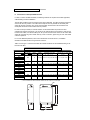
E. Conformance to European EMC Directive
In order to conform to EMC standards, the following methods are required for line filter application,
cable shielding and drive installation.
The line filter and Drive must be mounted on the same metal plate. The filter should be mounted as
close to the drive as practical. The cable must be kept as short as possible and the metal plate
should be securely grounded. The ground of the line filter and the drive must be bonded to the
metal plate with as much bare-metal contact as possible.
For main circuit input cables, a screened cable is recommended within the panel and is also
suggested for external connections. The screen of the cable should be connected to a solid ground.
For the motor cables, a screened cable (max. 20 m) must be used and the screen of the motor cable
should be connected to ground at both ends by a short connection, again using as much bare-metal
contact as practical.
For a more detailed explanation, refer to the manufacturer document TD 4077, “Installation
Guidelines For EMC Directive using AC Drive Products.”
Table 1-4 and Figure 1-4 show the line filter list for EMC standards and the installation/wiring of the
Drive and line filter.
Table 1-5. Line Filters for EMC Standards
Model
Part Number
Rated
FIL00
Current (A)
CIMR-V7NU
20P1
20P2
20P4
20P7
21P5
22P2
23P7
25P5
27P5
40P2
40P4
40P7
41P5
42P2
43P7
45P5
47P5
(1)
Line Filter
Weight
Dimensions in in. (mm)
lbs. (kg)
H x W x D (1)
Mounting Dim. in in. (mm) Screw
H1 x W1
Size
1083
10
1.8 (0.8)
7.6 x 3.2 x 2.0 (194 x 82 x 50)
7.1 x 2.4 (181 x 62)
M5
1084
16
2.2 (1.0) 6.7 x 4.4 x 2.0 (169 x 111 x 50)
6.1 x 3.6 (156 x 91)
M5
1085
26
2.4 (1.1) 6.9 x 5.7 x 2.0 (174 x 144 x 50) 6.3 x 4.7 (161 x 120)
M5
1100
50
5.1 (2.3) 12.0 x 7.2 x 2.2 (304 x 184 x 56) 11.3 x 5.9 (288 x 150)
M6
1086
5
2.2 (1.0) 6.7 x 4.4 x 1.8 (169 x 111 x 45)
6.1 x 3.6 (156 x 91)
M5
1087
10
2.2 (1.0) 6.7 x 4.4 x 1.8 (169 x 111 x 45)
6.1 x 3.6 (156 x 91)
M5
1088
15
2.4 (1.1) 6.9 x 5.7 x 2.0 (174 x 144 x 50) 6.3 x 4.7 (161 x 120)
M5
1101
30
5.1 (2.3) 12.0 x 7.2 x 2.2 (304 x 184 x 56) 11.3 x 5.9 (288 x 150)
M6
D is the distance the filter will extend outward from the surface of the metal plate.
4-d
H1
W1
D
W
1-12
H
1.4 ELECTRICAL INSTALLATION
L1 L2 L3
Continued
PE
Ground Bands (remove any paint)
V7N
DRIVE
MAINS
FILTER
LOAD
L1 L2 L3
L1 L2 L3
Cable Length
max. 40cm
Metal Plate
Motor Cable
max. 20m
Ground Bands (remove any paint)
IM
3~
Figure 1-4. Installation of Line Filter and V7N Drive
1-13
Continued
1.4 ELECTRICAL INSTALLATION
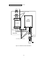
F. Interconnection - 2 Wire
NOTES FOR FIGURE 1-5
✱
– Indicates components not supplied.
– Main circuit terminal.
– Indicates control circuit terminal.
( ) – Indicates alternate terminal marking, i.e., (R) and L1.
▲
●
1.
– Function labels shown for these terminals are determined by factory settings of n050
through n056 (see paragraph 5.18).
– Function labels shown for these terminals are determined by factory settings of n057 through n059
(see paragraph 5.19).
Insulated twisted shielded wire is required.
2-conductor #18 GA. (Belden #8760 or equivalent).
3-conductor #18 GA. (Belden #8770 of equivalent).
Connect shield ONLY AT the Drive END (ground terminal
). Stub and isolate other end.
2.
The Drive’s Electronic Thermal Overload function (n036, n037) meets standards set by UL and CUL for motor
thermal overload protection. If local code requires a separate mechanical overload protection, an overload relay
should be installed, interlocked with the Drive as shown. It should be the manual reset type to prevent automatic
restart following a motor fault and subsequent contact reclosure after cool down.
3.
Customer to connect terminal
4.
For installation of Braking Resistor or Braking Resistor unit, refer to Appendix 6, “Dynamic Braking Option.”
5.
An optional DC reactor may be added for harmonic attenuation, if needed. See separate instruction sheet for wiring.
6.
If application does not allow reverse operation, parameter n006 , Reverse Run Prohibit Selection, should be set to
“ 1 ” (Reverse Run Disabled), and the Reverse Run/Stop input can be eliminated.
7.
Terminals S5-S7, MA and MC are not physical terminals, but they are multi-function inputs and outputs that are
controlled via DeviceNet communications.
to earth ground.
WARNING
8.
Input fuses are required for proper branch short circuit protection for all drives. Failure to use
recommended fuses (see Appendix 4) may result in damage to the drive and/or personal injury.
1-14
Continued
1.4 ELECTRICAL INSTALLATION
3-PHASE
POWER SUPPLY
(Use L1 (R) and
L2 (S) for
single-phase
input)
(Note that drive must
be derated by 50%
on 3-Phase Models)
MCCB
L1
*
L2
L3
FORWARD
RUN/STOP
*
1OL
(See
Note 3)
*
1-3 FU
(See Note 8)
REVERSE (See Note 6)
RUN/STOP
EXTERNAL
FAULT
FOR DC REACTOR
(See Note 5)
FOR DYNAMIC BRAKING
(See Note 4)
+1
B1
+2
–
L1 ( R )
L2 ( S )
L3 ( T )
* 1OL (See Note 2)
B2
T1 ( U )
V7N
T2 ( V )
T3 ( W )
*
AC
MOTOR
(See Note 3)
S1
(See Note 5)
S2
S3
FAULT
RESET
MULTI-FUNCTION
CONTACT INPUT
S4
MULTI-STEP
SPEED REF 1
MA
S5
MULTI-STEP
SPEED REF 2
JOG REFERENCE
MULTI-FUNCTION
DEVICENET OUTPUT
FAULT
S6
MULTI-FUNCTION
DEVICENET INPUT
S7
(See Note 7)
SC
LOGIC
COMMON
TERMINAL
MC
(See Note 7)
P1
RUNNING
PC
(See Note 1)
SHIELD
CONNECTION
BLACK
V-
BLUE
CAN_L
P2
MULTI-FUNCTION
PHOTOCOUPLER
OUTPUT
48V, 50mA OR LESS
SPEED
COINCIDENCE
DEVICENET
GREEN SHIELD TERMINALS
WHITE
CAN_H
RED
V+
FREQUENCY
SETTING
POT
MIN
SW1
BAUD RATE
1
0
9
1
0
9
2 3
8 7
4
5
6
1
0
9
2 3
8 7
2 3
8 7
MAX
PNP
NPN
CN2 V
I
C
4
5
6
4
5
6
0 ~ 10V
4 ~ 20 mA
Common
MULTI-FUNCTION
ANALOG INPUT
MSD LSD
ADDRESS
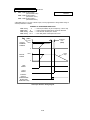
Figure 1-5. Standard Connections (2-Wire Control)
(Parameter n001 set to “10”)
FIG. 1-9
H. Inspection. After wiring is complete, verify that all wiring is correctly installed,
excess screws and wire clippings are removed from inside of unit, screws are
securely tightened, and exposed wire does not contact other wiring or terminals.
CAUTION
If a FWD or REV run command is given from the control
circuit terminal when the operation method selection
function ( n003 ) is set to “ 1 ” and the “LO/RE” selection
is set to “RE”, the motor will start automatically as soon
as power is applied to the main circuit.
1-15
Continued
1.4 ELECTRICAL INSTALLATION
G. Interconnection - 3 Wire
NOTES FOR FIGURE 1-6
✱
– Indicates components not supplied.
– Main circuit terminal.
– Indicates control circuit terminal.
( ) – Indicates alternate terminal marking, i.e., (R) and L1.
▲
●
1.
– Function labels shown for these terminals are determined by factory settings of n050
through n056 (see paragraph 5.18).
– Function labels shown for these terminals are determined by factory settings of n057 through n059
(see paragraph 5.19).
Insulated twisted shielded wire is required.
2-conductor #18 GA. (Belden #8760 or equivalent)
3-conductor #18 GA. (Belden #8770 or equivalent)
Connect shield only at the Drive end (ground terminal (
) ). Stub and isolate other end.
2.
The Drive’s Electronic Thermal Overload function (n036, n037) meets standards set by UL and CUL for motor thermal
overload protection. If local code requires a separate mechanical overload protection, an overload relay should be
installed, interlocked with the Drive as shown. It should be the manual reset type to prevent automatic restart following
a motor fault and subsequent contact reclosure after cool down.
3.
Customer to connect ground terminal (
4.
For installation of Braking Resistor or Braking Resistor Unit, refer to Appendix 6, “Dynamic Braking Option”.
5.
An optional DC reactor may be added for harmonic attenuation, if needed; see separate instruction sheet for wiring.
6.
If application does not allow reverse operation, parameter n006 , Reverse Run Prohibit Selection, should be set to “ 1 ”
(Reverse Run Disabled) and Fwd/Rev input can be eliminated.
7.
Terminals S5-S7, MA and MC are not physical terminals, but they are multi-function inputs and outputs that are
controlled via DeviceNet communications.
) to earth ground.
CAUTION
Parameter n050 must be set to “ 0 ”, AND parameter
n001 must be set to “ 11 ”. Resetting drive parameter
n001 to “ 10 ” may cause the motor to run in reverse
direction WITHOUT A RUN COMMAND, and possibly
result in equipment damage or personal injury.
WARNING
8.
Input fuses are required for proper branch short circuit protection for all drives. Failure to use recommended
fuses (see Appendix 4) may result in damage to the drive and/or personal injury.
1-16
Continued
1.4 ELECTRICAL INSTALLATION
3-PHASE
POWER SUPPLY
(Use L1 (R) and
L2 (S) for
single-phase
input)
(Note that drive must
be derated by 50%
on 3-Phase Models)
MCCB
L1
*
1-3 FU
(See Note 8)
*
FOR DYNAMIC BRAKING
(See Note 4)
+1
B1
+2
L2
L1 ( R )
L2 ( S )
L3
L3 ( T )
RUN
1OL
(See
Note 3)
FOR DC REACTOR
(See Note 5)
–
* 1OL (See Note 2)
B2
T1 ( U )
V7N
T2 ( V )
T3 ( W )
*
AC
MOTOR
(See Note 3)
S1
(See Note 6)
STOP
(See Note 5)
S2
REVERSE
S3
FAULT
RESET
MULTI-FUNCTION
CONTACT INPUT
S4
MULTI-STEP
SPEED REF 1
MA
S5
MULTI-STEP
SPEED REF 2
JOG REFERENCE
FAULT
S6
MULTI-FUNCTION
DEVICENET INPUT
S7
(See Note 7)
SC
LOGIC
COMMON
TERMINAL
MC
MULTI-FUNCTION
DEVICENET OUTPUT
(See Note 7)
P1
RUNNING
PC
(See Note 1)
SHIELD
CONNECTION
BLACK
V-
BLUE
CAN_L
P2
MULTI-FUNCTION
PHOTOCOUPLER
OUTPUT
48V, 50mA OR LESS
SPEED
COINCIDENCE
DEVICENET
GREEN SHIELD TERMINALS
WHITE
CAN_H
RED
V+
FREQUENCY
SETTING
POT
MIN
SW1
BAUD RATE
1
0
9
1
0
9
2 3
8 7
4
5
6
1
0
9
2 3
8 7
2 3
8 7
MAX
PNP
NPN
CN2 V
I
C
4
5
6
4
5
6
0 ~ 10V
4 ~ 20 mA
Common
MULTI-FUNCTION
ANALOG INPUT
MSD LSD
ADDRESS
Figure 1-6. Standard Connections (3-Wire Control)
(Parameter n001 set to “11”)
H. Inspection. After wiring is complete, verify that all wiring is correctly installed,
excess screws and wire clippings are removed from inside of unit, screws are
securely tightened, and exposed wire does not contact other wiring or terminals.
CAUTION
If a FWD or REV run command is given from the control
circuit terminal when the operation method selection
function ( n003 ) is set to “ 1 ” and the “LO/RE” selection
is set to “RE”, the motor will start automatically as soon
as power is applied to the main circuit.
1-17
1-18
Section 2. INITIAL START-UP
2.1 PRE-POWER CHECKS
• Verify wires are properly connected and no erroneous grounds exist.
• Remove all debris from the Drive enclosure, such as loose wire clippings, metal shavings, etc.
• Verify all mechanical connections inside the Drive are tight.
• Verify motor is not connected to load.
• Apply input power only after the front cover is in place. DO NOT remove the front cover or Digital
Operator while input power is on.
• Determine the proper control method for the application.
Open Loop Vector Control - Use section 2.2 for startup instructions
Parameter n002 = 1. Open Loop Vector Control method should be used for
most constant torque applications of the Drive. With this control method
there is excellent starting torque and excellent speed regulation. The startup
procedure for this control method is slightly more complicated.
V/f Control - Use section 2.3 for startup instructions
Parameter n002 = 0. V/f control should be used for most variable torque
applications. Variable torque applications would include: fan, blower,
centrifugal pump, and mixers. Generally variable torque loads do not require
high levels of starting torque. V/f control can also be used for some constant
torque loads where starting torque and speed regulation are not critical.
2-1
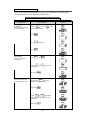
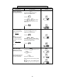
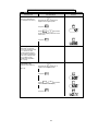
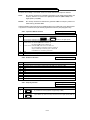
2.2 OPEN LOOP VECTOR STARTUP
NOTE: 2-wire, 3-wire, or DeviceNet sequence selection must be made prior to using this startup
procedure or making any other adjustments (parameter n001).
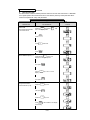
Table 2-1. Open Loop Vector Startup Procedure
DESCRIPTION
Set the highest parameter
access level.
This will allow all parameters
to be viewed and set.
DIGITAL OPERATOR
DISPLAY
KEY SEQUENCE
DSPL
Press the
key until the
is lit on the digital operator.
Press
DATA
ENTER
PRGM
LED
PRGM
PRGM
.
V
Press
Press
Set drive for Open Loop
Vector control.
This is accomplished by
setting n002 = 1
DATA
ENTER
PRGM
.
V
Press
DATA
ENTER
then
V
Use the
in the display.
Then press
Set motor rated voltage.
(This can be obtained from
the nameplate of the motor.)
PRGM
three times.
V
&
DATA
ENTER
.
keys to set a “1”
PRGM
PRGM
PRGM
.
V
Press and hold
until n012 is
displayed on the digital operator.
Then press
DATA
ENTER
PRGM
PRGM
.
(1)
V
V
Use the
&
keys until the
number in the display matches the motor
rated voltage.
Then press
DATA
ENTER
PRGM
(1)
PRGM
.
2-2
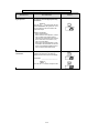
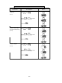
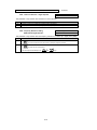
Table 2-1. Open Loop Vector Startup Procedure - Continued
DESCRIPTION
Set motor rated current.
(This can be obtained from
the nameplate of the motor.)
KEY SEQUENCE
DIGITAL OPERATOR
DISPLAY
V
Press and hold
until n036 is
displayed on the digital operator.
Then press
DATA
ENTER
PRGM
.
(1)
V
V
Use the
&
keys until the
number in the display matches the motor
rated current.
Then press
Set the motor rated slip.
This can be calculated by
using the following formula:
V
Then press
Example:
Slip = (1800 - 1725) * 4
120
PRGM
.
Press and hold
until n106 is
displayed on the digital operator.
Slip = (Ns-Nr) * P
120
Where:
Ns = Motor synch. speed (2)
Nr = Motor rated speed
P = Number of motor poles
DATA
ENTER
DATA
ENTER
PRGM
.
(1)
V
V
Use the
&
keys until the
number in the display matches the calculated
slip value (see equation at left).
Then press
DATA
ENTER
PRGM
.
Slip = 2.5
Prepare to test run the
drive from the Digital
Operator. Motor should be
disconnected from the load.
Press and hold
the
This will set the drive into the
“Local” mode and bring up
the motor current display.
LO/RE
DSPL
several times until
LED is lit.
LO/RE
V
Press the
LO/RE
key once.
Display the drive’s output current by pressing
IOUT
DSPL
four times. Turn the Digital Operator
Pot all the way to the left (counter-clockwise.
2-3
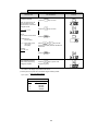
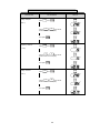
Table 2-1. Open Loop Vector Startup Procedure - Continued
DESCRIPTION
Test run the drive from the
Digital Operator.
KEY SEQUENCE
DIGITAL OPERATOR
DISPLAY
WARNING: The next key press will cause
the motor to turn! Take appropriate safety
precautions!
RUN
Press the
key then slowly turn the
Digital Operator Pot to the right about 1/4 of a
turn. The display on the drive will show the
actual motor amps.
IOUT
(1)
Operation checkpoints:
• Motor rotates smoothly
• Motor rotates in correct direction. (If motor
does not rotate in the proper direction,
stop the motor and remove power from the
Drive. Switch motor connections T1 (U)
and T2 (V) at the Drive.)
• Motor has no abnormal vibration or noise.
• Acceleration and deceleration are smooth.
• Unit is not overloaded. (Displayed current
does not exceed drive rated current).
Determine the motor “no
load current.”
With the drive still running, turn the Digital
Operator Pot all the way to the right (full
speed) and record the current on the display.
IOUT
(1)
Actual Value: ________________________
Press the
STOP
RESET
button to stop the drive.
2-4
IOUT
Table 2-1. Open Loop Vector Startup Procedure - Continued
DESCRIPTION
KEY SEQUENCE
Set the motor “no load
current” in the drive.
Press the
Motor no load current is set
as a percentage of motor
rated current. It is calculated
using the formula:
DSPL
PRGM
V
Press the
Inoload *100 = n110
Irated
key four times.
DIGITAL OPERATOR
DISPLAY
Where:
Inoload = Motor no load current
Press the
key four times.
DATA
ENTER
key.
PRGM
PRGM
(measured in the
previous step)
Irated = Motor rated current
(from motor
nameplate)
(1)
V
Example:
2.5 * 100 = 60
4.2
Press the
This completes the startup.
Make further programming
changes as required.
V
Use the
&
keys until the
number in the display matches calculated noload current.
DATA
ENTER
key.
DSPL
Press the
key to get out of the
programming mode.
(1)
The number in the display may be different than shown.
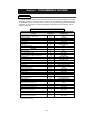
(2)
Motor synchronous speed can be calculated using the following formula:
120 x motor rated frequency
synch. speed =
number of motor poles
For 60 Hz Rated Motors
Poles
Synchronous Speed
2
3600 RPM
4
1800 RPM
6
1200 RPM
8
900 RPM
2-5
PRGM
FREF
(1)
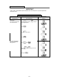
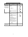
2.3 V/f STARTUP PROCEDURE
IMPORTANT
2-wire, 3-wire, or DeviceNet sequence selection must be made prior to any other adjustments
(Parameter n001).
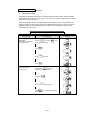
Table 2-2. V/f Startup Procedure
DESCRIPTION
Set the highest parameter
access level.
This will allow all parameters
to be viewed and set.
DIGITAL OPERATOR
DISPLAY
KEY SEQUENCE
PRGM
DSPL
Press
key until the
on the digital operator.
Press
DATA
ENTER
PRGM
LED is lit
PRGM
.
V
Press
Press
Set drive for V/f control.
This is accomplished by
setting n002 = 0
PRGM
three times.
DATA
ENTER
PRGM
.
V
Press
DATA
ENTER
then
V
Use the
in the display.
Then press
V
&
DATA
ENTER
.
keys to set a “0”
PRGM
PRGM
PRGM
.
2-6
Table 2-2. V/f Startup Procedure - Continued
DESCRIPTION
Set motor rated current.
(This can be obtained from
the nameplate of the motor.)
KEY SEQUENCE
DIGITAL OPERATOR
DISPLAY
V
Press and hold
until n036 is
displayed on the digital operator.
Then press
DATA
ENTER
PRGM
.
(1)
V
V keys until the
Use the
&
number in the display matches the motor
rated current.
Then press
DATA
ENTER
PRGM
.
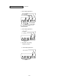
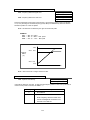
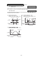
Set the V/f pattern.
Parameters n011 through
n017 set the V/f pattern. Table
5-4 in section 5.27 lists
recommended V/f patterns.
The numbers in parentheses
shown in the example below
are for a 460V / 60 Hz
variable torque application
(fan or pump).
Set Parameter n011Maximum output frequency.
(60.0 Hz)
V
Press and hold
until n011 is
displayed on the digital operator.
Then press
DATA
ENTER
PRGM
.
(1)
V
V
Use the
&
keys until the
desired number is in the display.
Then press
DATA
ENTER
PRGM
(1)
PRGM
.
2-7
Table 2-2. V/f Startup Procedure - Continued
DESCRIPTION
Set Parameter n012Voltage Max.
KEY SEQUENCE
V
Press
DATA
ENTER
then
.
DIGITAL OPERATOR
DISPLAY
PRGM
(460.0 V)
(1)
V
V
Use the
&
keys until the
desired number is in the display.
DATA
ENTER
Then press
Set Parameter n013Frequency at max. voltage
point (motor rated frequency)
DATA
ENTER
then
(1)
PRGM
.
V
Press
PRGM
.
PRGM
(1)
(60.0 Hz)
V
V
Use the
&
keys until the
desired number is in the display.
DATA
ENTER
Then press
Set Parameter n014Frequency - Midpoint
DATA
ENTER
then
(1)
PRGM
.
V
Press
PRGM
PRGM
.
(30.0 Hz)
(1)
V
V
Use the
&
keys until the
desired number is in the display.
Then press
DATA
ENTER
PRGM
(1)
PRGM
.
2-8
Table 2-2. V/f Startup Procedure - Continued
DESCRIPTION
Set Parameter n015Voltage - Midpoint
KEY SEQUENCE
V
Press
DATA
ENTER
then
.
DIGITAL OPERATOR
DISPLAY
PRGM
(80.4 V)
(1)
V
V keys until the
Use the
&
desired number is in the display.
DATA
ENTER
Then press
Set Parameter n016Frequency - Minimum
DATA
ENTER
then
(1)
PRGM
.
V
Press
PRGM
.
PRGM
(1.5 Hz)
(1)
V
V
Use the
&
keys until the
desired number is in the display.
Then press
Set Parameter n017Voltage - Minimum
DATA
ENTER
DATA
ENTER
then
(1)
PRGM
.
V
Press
PRGM
.
PRGM
(18.4 V)
(1)
V
V keys until the
Use the
&
desired number is in the display.
Then press
DATA
ENTER
PRGM
(1)
PRGM
.
2-9
Table 2-2. V/f Startup Procedure - Continued
DESCRIPTION
Prepare to test run the
drive from the Digital
Operator. Motor should be
disconnected from the load.
This will set the drive into the
“Local” mode, and bring up
the motor current display.
KEY SEQUENCE
DSPL
Press
LED is lit.
several times until the “LO/RE”
DIGITAL OPERATOR
DISPLAY
LO/RE
V
Press the
key once.
LO/RE
Display the drive’s output current by pressing
IOUT
DSPL
four times. Turn the Digital Operator
Pot all the way to the left (counter-clockwise).
Test run the drive from the
Digital Operator
WARNING: The next key press will cause
the motor to turn! Take appropriate safety
precautions!
RUN
Press the
key then slowly turn the
Digital Operator Pot to the right about 1/4 of a
turn. The display on the drive will show the
actual motor amps.
Operation checkpoints:
• Motor rotates smoothly
• Motor rotates in correct direction. (If motor
does not rotate in the proper direction,
stop the motor and remove power from the
Drive. Switch motor connections T1 (U)
and T2 (V) at the Drive to change
direction).
• Motor has no abnormal vibration or noise.
• Acceleration and deceleration are smooth.
• Unit is not overloaded. (Displayed current
does not exceed drive rated current).
Press the
STOP
RESET
key.
This completes the startup.
Make further programming
changes as required.
(1)
The number in the display may be different than shown.
2-10
IOUT
(1)
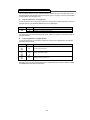
Section 3. OPERATION AT LOAD
After completing the start-up, and programming of constants, turn off the AC main circuit power.
Make additional wiring connections required for the external control functions selected by the
constant programming. Connect the driven machine to the motor. Verify that the driven machine is
in running condition, and that no dangerous conditions exist around the drive system.
CAUTION
•
Before applying a RUN command to the Drive, verify that the motor is stopped.
•
NEVER use a motor whose full-load amps exceeds the Drive rating.
•
When starting and stopping the motor, use the operation signals (RUN/STOP, FWD/REV),
NOT a magnetic contactor on the power supply side.
Run the motor under load with control by the Digital Operator using the same procedure as for the
Initial Start-up. If the Digital Operator is used in combination with external commands or external
commands only are used, the procedure must be altered accordingly.
3-1
3-2
Section 4. DIGITAL OPERATOR
4.1 GENERAL
All functions of the Drive are accessed using the Digital Operator. In addition to controlling motor
operation, the operator can enter information into the Drive memory to configure the Drive’s
application, by using the Function LEDs.
4.2 DIGITAL OPERATOR
A.
Digital Operator Description
The Digital Operator has a 4-digit LED display. Both numeric and alpha-numeric data can appear on
the display. Indicators and keys on the Digital Operator are described in Figure 4-1.
Display section
Data display
section
DIGITAL
OPERATOR
JVOP-140
Function
LEDs
FREF
FOUT
F/R
Press to switch
between function
LEDs.
DSPL
IOUT
MNTR
LO/RE
PRGM
V
Digital Operator
Potentiometer
(Pot)
RUN
MIN
DATA
ENTER
MAX
STOP
RESET
V
Displays data
to be changed
and enters new
data.
Press to run the motor.
Press to increase
parameter no./data
value.
Press to decrease
parameter no./data
value.
Status indicator
Figure 4-1. Digital Operator
4-1
Press to stop the motor,
or reset a drive fault
4.2 DIGITAL OPERATOR
Continued
B. Description of Function LEDs
By pressing the DSPL key on the Digital Operator, the operator can step to each of the seven
Function LEDs and its associated display/setting function:
Press
Press
FREF
DSPL
F/R
DSPL
FOUT
Press
DSPL
IOUT
DSPL
LO/RE
DSPL
Press
MNTR
DSPL
PRGM
DSPL
Press
Press
Press
FREF
—
Frequency Reference Setting
Sets/Displays the Drive operation speed (Hz).
FOUT
—
Output Frequency Monitor
Displays the output frequency (Hz) at which the Drive is currently
operating. This is a monitor only function; the operator cannot
change the displayed value by use of the keypad.
IOUT
—
Output Current Monitor
Displays the level of output current (Amps) that the Drive is
currently producing. This is a monitor only function; the operator
cannot change the displayed value by use of the keypad.
MNTR
—
Monitor Selection
Pressing ENTER allows access to the various Monitor parameters,
U-01 through U-10. These are monitor only functions; the operator
cannot change the displayed value. Accessible during run command.
See section 4.4. for complete listing of all monitor parameters.
F/R
—
FWD/REV Run Selection
Sets the rotation direction of the motor when a Run command is
given by the Digital Operator keypad. Display of For = forward run,
rEu = reverse run.
LO/RE
—
Local / Remote Selection
This toggles between the Local (Digital Operator) and Remote (set by
parameters n003 & n004) modes of operation. This affects both the
start/stop functions, as well as the frequency reference. Local / Remote
status cannot be changed using this LED when a multi-function input
terminal is set for Local/Remote (n050 through n056 set for “17”).*
PRGM
—
Parameter Programming
Selects or reads data using parameter number (nXXX). Data is
displayed by pressing the ENTER key, and can be changed by
pressing the “up arrow” or “down arrow” keys. Any changes can be
saved by again pressing the ENTER key. Pressing the DSPL key
exits the Programming mode.*
* The RUN command will not be accepted by the drive when the LO/RE or PRGM Function LEDs are
lit. Select any other Function LED to allow the drive to accept RUN command.
4-2
4.3 STATUS INDICATOR LEDs
There are two indicator LEDs on the front of the Drive. The drive status is indicated by various
combinations of ON, Blinking, and OFF conditions of these two LEDs:
(Green)
RUN
(Red)
ALARM
Operation Ready (during stop)
Ramp to Stop (during decel)
Blinking
Long Blinking
Off
Off
Normal Operation (running)
Alarm
On
Blinking or ON
Off
Blinking
Off
On
CONDITION
Fault
For details of how the status indicator LEDs function during a drive fault, refer to the
“TROUBLESHOOTING” section.
4.4 DEVICENET LEDs
The Drive has two LEDs (MS and NS) on the front cover to indicate DeviceNet communications
status. The table below describes the function of DeviceNet specific LEDs.
LED
Name
Display
Color Status
Green
Lit
Operation Status
Description
During drive operation
The drive is operating normally.
Green Flashing During drive initialization
MS
Red
Red
Lit
Initial setting status or communication not ready.
Unrecoverable fault
An unrecoverable fault occurred in the drive.
Flashing Recoverable fault
—
Not lit
Green
Lit
A recoverable fault occurred, such as switch
setting error.
Power OFF
Power not being supplied to the drive.
DeviceNet communication taking
place
DeviceNet communicating normally.
Green Flashing DeviceNet communication not
taking place
NS
Red
Red
—
Lit
A fault that makes it impossible for the
DeviceNet to communicate occurred.
• Duplicate MAC ID
• Bus-off detection
Communication fault
Flashing Communication timeout
Not lit
DeviceNet network normal, but not
communicating with the master.
Communication timeout with master occurred.
DeviceNet not set to Online.
Power not being supplied to the interface card.
Mismatch of baud rate.
Offline, Power OFF
NOTE: The LEDs will flash red once (100ms) during power up initialization. This is used in the
internal testing process to verify that the red LED is working properly.
4-3
4.4 DEVICENET LEDs
Continued
RUN
ALARM
MS
NS
4-4
4.5 MONITOR DISPLAYS
When using the Monitor Function, a variety of information will appear on the Digital Operator
display when each of the U-XX (display only) parameters is selected.
Monitor
Contents
Display Example
MEMOBUS Address (hex)
U-01
Frequency reference (Hz)
60.0
23
U-02
Output frequency (Hz)
60.0
24
U-03
Output current (A)
12.5
3B
U-04
AC output voltage (V)
230
28
U-05
DC Bus voltage (VPN)
325
31
U-06
Multi-function input terminal and
DeviceNet input status
(1)
2B
U-07
Multi-function output terminal and
DeviceNet output status
(2)
2D
U-08
Motor torque (%)
(Open loop vector only)
U-09
72
32
Fault history
(last 4 faults)(3)
1.bUS
1B2
U-10
Software number
XXXX
0010
1B3
U-11
Output power (KW)
99.9
37
U-12
Reserve (Not displayed)
U-13(1)
Elapse time
(0-6550 (x 10hour))
-
-
1234
35
-
U-14
Reserve (N/A)
-
U-15
Reserve (N/A)
-
-
U-16
PID feedback (%)
35.0
38
U-17
PID input (%)
100
39
U-18
PID output (%)
75.5
3A
U-19
Reserve (Not displayed)
-
-
U-60
DeviceNet Polled Producing
Attribute (PPA)
70: Basic speed control
71: Extended Speed Control
(Readable via DeviceNet Object Class
150: V7N Memobus I/O Control
5, Instance 2, Attribute 10)
151: V7N Standard Drive Control
152: V7N Accel/Decel Time Control
155: V7N Extended I/O MEMOBUS
Instance
156: V7N General Purpose DI/DO
Instance
U-61
DeviceNet Polled Consuming
Attribute (PCA)
20: Basic speed control
21: Extended Speed Control
(Readable via DeviceNet Object Class
100: V7N Memobus I/O Control
5, Instance 2, Attribute 10)
101: V7N Standard Drive Control
102: V7N Accel/Decel Time Control
105: V7N Extended I/O MEMOBUS
Instance
106: V7N General Purpose DI/DO
Instance
U-62
DeviceNet MAC ID switch setting
(S3 x 10 + S4)
17
-
U-63
DeviceNet MAC ID set
17
(Readable via DeviceNet Object Class
3, Instance 1, Attribute 1)
U-64
DeviceNet Baud Rate switch setting
(S1)
1
-
U-65
DeviceNet Baud Rate set
U-66
DeviceNet connection status
125: 125 kbps
250: 250 kbps
500: 500 kbps
(Readable via DeviceNet Object Class
3, Instance 1, Attribute 2)
(4)
(1) Available only in CIMR-V7NU25P5, 27P5, 45P5, and 47P5 drives
4-5
(Readable via DeviceNet Object Class
5, Instance 1 and 2, Attribute 1)
4.5 MONITOR DISPLAYS
Continued
(1)
Actual display appearance:
Term. S1 input OPEN
Term. S2 input CLOSED
Term. S3 input OPEN
Term. S4 input CLOSED
Term. S5 input OPEN
Term. S6 input CLOSED
Term. S7 input OPEN
Not used
(2)
Actual display appearance:
{
MA-MC CLOSED
P1 - PC OPEN
P2 - PC CLOSED
Not used
(3)
See section 6 for viewing
of fault log contents.
(4)
Actual display appearance:
{
Polled Messaging
Explicit Messaging
Not used
4-6
Section 5. PROGRAMMABLE FEATURES
5.1 GENERAL
This section describes features of the Drive which are defined by programmed settings in the various
parameters in memory. Since most features use more than one parameter, the descriptions appear
in alphabetical order by the function name. In Table 5-1, the functions are grouped into operational
categories. To cross reference a particular parameter to the features to which it applies, see the
listings in Appendix 1.
Table 5-1. List of Features Defined By Parameters
PARAGRAPH
REFERENCE
PARAMETER(S)
5.18
5.24
5.22
2.2
5.26
n001
n011 - n017
n036 - n038
n002
n176, n177
STARTING
Accel Time
S-Curve Characteristics
DC Injection Braking at Start
5.2
5.3
5.7
n018, n019, n021
n023
n089, n091
STOPPING
Stopping Method
Decel Time
DC Injection Braking at Stop
5.21
5.2
5.7
n005
n018, n020, n022
n089, n090
SPEED CONTROL
Frequency Reference, Upper & Lower Limits
Jog Reference*
Frequency Reference Selection
Multi-step Speed Setting*
5.9
5.12
5.11
5.11
FUNCTION
SET-UP
Initialization (Reset), 2-Wire or 3-Wire
Volts/Hertz Patterns
Thermal Motor Overload Protection
Control Method Selection
Copy Function
Up/Down Frequency Setting
DeviceNet Control
PID Control
5.10, 5.15E
6.3.1
5.25
n033, n034
n032, n050 - n056
n004, n008, n009
n004, n024 - n031
n050 - n056, n120 - n127
n056, n100
n003, n004, n148 - n157
n128 - n138, n163, n164
REVERSE
Reverse Run Disabled
Critical Frequency Rejection
Carrier Frequency
Speed Search*
Speed Coincidence*
Slip Compensation
Table A1-1
5.6
5.5
5.15D
5.16
5.19
n006
n083 - n086
n080, n175
n050 - n056
n057 - n059, n095
n036, n106, n110 - n113
RUNNING IMPROVEMENTS
Torque Compensation
Stall Prevention
Energy Saving
5.23
5.20
5.28
n103 - n105, n109
n092 - n094, n115, n116
n139 - n146, n158 - n162
PROTECTIVE FEATURES
Momentary Power Loss Ride-thru
Auto Restart
Overtorque/Undertorque Detection*
Miscellaneous Protective Functions
5.14
5.4
5.17, 5.31
5.13
n081
n082
n057 - n059, n096 - n099
n007, n010
DRIVE CONTROLS, INPUT
Multi-function Input Terminals*
External Fault Terminals*
Multi-function Analog Input CN2
5.15
5.16
5.29
n050 - n056
n057 - n059
n077-n078
DRIVE OUTPUT
Multi-function Output Terminals*
5.16
n057 - n059
* Terminals S5-S7 and MA are not physical terminals, but they are multi-function inputs and outputs controlled via
DeviceNet communications.
5-1
5.2 ACCEL/DECEL TIME
A.
n019 : Accel Time 1
n020 : Decel Time 1
Factory setting (each): 10.0 seconds
Range (each): 0.00 to 6000.0 seconds
n021 : Accel Time 2
n022 : Decel Time 2
Factory setting (each): 10.0 seconds
Range (each): 0.00 to 6000.0 seconds
n041 : Accel Time 3
n042 : Decel Time 3
Factory setting (each): 10.0 seconds
Range (each): 0.00 to 6000.0 seconds
n043 : Accel Time 4
n044 : Decel Time 4
Range (each): 0.00 to 6000.0 seconds
Factory setting (each): 10.0 seconds
The drive incorporates four sets of individually programmable acceleration and deceleration times.
Four acceleration and deceleration times can be selected if two Multi-Function Input Terminals
(n050 to n056) are set to ‘11’ (accel/decel time 1) and ‘27’ (accel/decel time 2).
B.
n050 thru n056 : Multi-function Inputs
(Term. S1 thru S7)
Data 11 : Accel/Decel Time Selection 1
Data 27 : Accel/Decel Time Selection 2
The following table shows which acceleration and deceleration times are selected by each
combination of accel/decel time select 1 (n050 thru n056 =11) and accel/decel time select 2
(n050 thru n056 = 27).
Accel/decel time
Select 1 (terminal S1
Accel/decel time
Select 2 (terminal S1
thru S7)
thru S7)
OPEN
C.
Acceleration time
Deceleration time
OPEN
Acceleration time 1
Deceleration time 1
CLOSED
OPEN
n019
Acceleration time 2
n020
Deceleration time 2
OPEN
CLOSED
n021
Acceleration time 3
n041
n022
Deceleration time 3
n042
CLOSED
CLOSED
Acceleration time 4
n043
Deceleration time 4
n044
n018 : Accel Time Setting Unit
Factory setting: 0
Range : 0 = 0.1 seconds
1 = 0.01 seconds
In addition to determining the setting resolution, this parameter controls the range of n019 thru n022; if
the resolution is 0.01 sec., the range is 0.00 to 600.00 sec. If the resolution is set to 0.1 sec., the range
is 0.0 to 6000.0 sec.
5-2
5.3 ACCEL/DECEL: S-CURVE CHARACTERISTICS
n023 : S-Curve Selection
Factory setting: 0
Range: 0 to 3
Setting of this parameter
determines the S-curve
(starting) characteristics
of the acceleration ramp.
0 = S-curve disabled
1 = S-curve
of 0.2 seconds
2 = S-curve time
of 0.5 seconds
3 = S-curve time
of 1.0 seconds
RUN
OUTPUT
FREQUENCY
FREQ
COMMAND
Accel ramp per
selected Accel Time
(n019 or n021 )
0
TIME
S-Curve Characteristics
Time (TSC)
NOTE: Actual accel time = Set accel time + (2 * S-curve selection)
Actual decel time = Set decel time + (2 * S-curve selection)
The following figure shows FWD/REV switching and acceleration & deceleration to a stop with
S-curve active.
FORWARD RUN COMMAND
REVERSE RUN COMMAND
DECELERATION
OUTPUT FREQUENCY ACCELERATION
MIN. OUTPUT
FREQUENCY
n016
DC INJECTION
TIME AT STOP
n090
n016
DECELERATION
ACCELERATION
= S-CURVE CHARACTERISTIC
5-3
5.4 AUTO-RESTART
A.
n082 : Number of Auto-Restart Attempts
Factory setting: 0
Range: 0 - 10
When a fault occurs during operation, the Drive can be programmed for an auto-restart operation to
automatically reset the fault. Auto-restart operation will use the number of reset attempts set in this
parameter, up to the maximum of 10. When set to " 0 ", no auto-restarts will be attempted.
Fault contact will not actuate (change state) during auto-restart attempts.
• The following faults can be automatically reset:
oC:
ou:
Overcurrent
Overvoltage (OV)
• The number of restart attempts available will be reset to the n082 setting when:
1. 10 minutes has elapsed without a fault occurring.
2. The RESET key, or external Fault Reset push button, is pressed.
3. Power is removed from the Drive.
5.5 CARRIER FREQUENCY
n080 : Carrier Frequency
Factory Setting: 3
Range: 1 to 4; 7 to 9
The relationship between output frequency and carrier frequency is determined from the set value
of n080 .
(a) For constant carrier frequency, set to " 1 ", " 2 ", " 3 ", " 4 ".
(b) For synchronous mode, set n080 to " 7 ", " 8 ", or " 9 ". These setting values
establish carrier frequencies of 12f, 24f, or 36f, respectively.
n080
SETTING
1
2
3
4
7
8
9
CARRIER FREQUENCY(kHz)
Maximum(FcMAX)
Minimum(FcMIN)
SLOPE
(=Fc)
Fo
2.5
5.0
7.5
10.0
1.0
1.0
1.0
0
0
0
0
12
24
36
2.5
5.0
7.5
10.0
2.5
2.5
2.5
OUTPUT FREQUENCY(Hz)
F1
F2
NA
NA
NA
NA
83.3
41.6
27.7
NA
NA
NA
NA
208.3
104.1
69.4
Fc MAX
CARRIER
FREQUENCY
SLOPE
Fc MIN
0
F1
F2
OUTPUT FREQUENCY
5-4
MODE
CONSTANT
SYNCHRONOUS
DRIVE DERATING FOR HIGHER CARRIER FREQUENCY
Setting carrier frequency to a value higher than its factory setting requires derating of the drive’s output
current - refer to the following table:
Rated
input
n080
Rated Output
Current (A)
20P1
20P2
0.8
1.6
20P4
20P7
3.0
5.0
4
4
10
10
21P5
22P2
23P7
8.0
11.0
17.5
3
3
3
7.5
7.5
7.5
7.0
10.0
16.5
25P5
27P5
25.0
33.0
3
3
7.5
7.5
23.0
30.0
40P2
40P4
1.2
1.8
3
3
7.5
7.5
1.0
1.6
40P7
41P5
43P7
3.4
4.8
8.6
3
3
3
7.5
7.5
7.5
3.0
4.0
No Derate
45P5
47P5
14.8
18.0
3
3
7.5
7.5
14.0
17.0
Factory
Setting
4
4
Frequency
(kHz)
10
10
230V
460V
Derated
Output
Current (A)
New Drive Model No.
CIMR-V7NU
(1)
No
Derate
(1) Derated Output Current values are the maximum currents available with a
carrier frequency n080 setting of “4” (10kHz).
Carrier frequency should be decreased as the distance between the drive and the motor increases,
to reduce capacitive coupling in the motor leads.
• For wiring distances greater than 100m (328 ft.), n080 should be set to 5 kHz (data " 2 " )
or less.
n175 : Reduce carrier at low speed selection
Factory Setting: 0
Range: 0 or 1
SETTING
0
1
DESCRIPTION
Disabled
Carrier frequency reduced to 2.5 KHz
When n175 is enabled (= “1”), the carrier frequency will automatically be reduced to 2.5 kHz,
regardless of the setting of n080, whenever the output frequency is at or below 5 Hz AND the
output current is above 110% of drive rated current.
5-5
5.6 CRITICAL FREQUENCY REJECTION
A.
n083 : Prohibited Frequency 1
n084 : Prohibited Frequency 2
n085 : Prohibited Frequency 3
Factory setting (each): 0.00
Range (each): 0.00 to 400.0 Hz
These parameters allow programming of up to three prohibited frequency points for eliminating
problems with resonant vibration of the motor/machine. This feature does not actually eliminate the
selected frequency values, but will accelerate and decelerate the motor through the prohibited
bandwidth.
B.
n086 : Prohibited Frequency Deadband
Factory setting: 0.00
Range: 0.00 to 25.50 Hz
This parameter determines the width of the deadband around each selected prohibited frequency
point.
EXAMPLE:
Vibration encountered between 30.00 and 36.00 Hz.
SOLUTION:
Set n083 to " 33.00 ". This is the center of the problem
frequency band.
Set n086 to " 3.00 ". This will cause the Drive to reject all
frequency command values between 30.00 and 36.00 Hz.
A frequency command in the deadband will be converted to the bottom
value of the deadband, e.g. a command of 33.00 Hz would result in a run
frequency of 30.00 Hz.
Total Deadband = 6.00 Hz
FREQ. CMD
36.00 Hz
n083 = 33.00 Hz
30.00 Hz
± n086 (3.00 Hz)
0
OUTPUT FREQUENCY (Hz)
NOTE: n083 > n084 > n085 - The highest prohibit frequency required needs to be in n083.
The next highest prohibit frequency needs to be in n084, and the lowest prohibit frequency
needs to be in n085.
5-6
5.7 DC INJECTION BRAKING
n016 : Minimum Frequency
Range: 0.1 to 10.0 Hz
n089 : DC Injection Braking Current
(% of Drive Rated Current)
Factory setting: 50 %
Range: 0 to 100 %
n090 : DC Injection Time at Stop
Factory setting: 0.5 sec
Range: 0.0 to 25.5 sec
n091 : DC Injection Time at Start
Factory setting: 0.0 sec
Range: 0.0 to 25.5 sec
DC injection can be used to stop a motor whose rotational direction is uncertain at start-up, or to
help stop a coasting motor.
With ramp to stop enabled (n005 = " 0 " ), after a STOP command is received the Drive controls
motor deceleration according to the Decel Time setting, until output frequency reaches the DC
injection braking start frequency (or Minimum Frequency, n016 ). Then the Drive output is turned off
and DC injection current is applied to the motor. The effective DC injection time and current should
be set to provide adequate stopping without excessive motor heating. The DC injection voltage is
determined by the DC injection braking current and motor impedance.
STOP
RUN COMMAND
RAMP TO STOP
DC
OUTPUT FREQUENCY
DC INJECTION TIME AT
START (n091 )
MINIMUM
FREQUENCY (n016 )
DC INJECTION TIME AT
STOP (n090 )
DC Braking Sequence
5-7
DC
5.8 FREQUENCY REFERENCE UPPER & LOWER LIMITS
n033 : Frequency Reference Upper Limit
Factory setting: 100 %
Range: 0 to 110 %
n034 : Frequency Reference Lower Limit
Factory setting: 0 %
Range: 0 to 110 %
These two parameters set the range for the frequency command signal. Each is set, in increments
of 1%, as a percentage of maximum frequency (Fmax; n011 ) as established by either the selected
standard V/f pattern or custom V/f pattern.
NOTE: All references are affected by the upper and lower limit points.
EXAMPLE:
n011 = " 60 " Hz (100%)
n033 = " 80 " % = 48Hz – Max. speed
n034 = " 10 " % = 6Hz – Min. speed
100%
n033
80%
OUTPUT
FREQ.
(%)
n034 10%
2.5%
t
NOTE: n033 must be set to a higher value than n034.
5.9 FREQUENCY REFERENCE RETENTION
n100 : Up/Down Hold Memory
Factory setting: 0
Range: 0 or 1
Used with the Up/Down command. To retain the held frequency reference when a stop command is
issued or when power is removed, set n100 to " 1 ".
Setting
Description
0
Not retained
1
Held reference retained
Note: Frequency reference value must
remain unchanged for a minimum of 5
seconds to be retained.
5-8
5.10 FREQUENCY REFERENCE SELECTION
The Drive allows selection of up to nineteen frequency references. One is an analog input, sixteen
are digital presets (selected with multi-function inputs), one is a jog input, and one is via DeviceNet
communications (see paragraph 5.32).
A.
Frequency Reference via Analog Input
In order to set the Drive so the frequency reference comes from the analog input CN2 connector on
the digital operator, set parameter n004 as shown in the table below:
PARAMETER
n004
SETTING
7
8
DESCRIPTION
Sets CN2 for a voltage input (0 to 10V)
Sets CN2 for a current input (4 to 20mA)
The Analog Input Connector/Cable Assembly Option (DS082) is required for interface with CN2 on
the digital operator.
B.
Frequency Reference via Digital Presets
In order to set the Drive so the frequency reference comes from the digital presets, the following
parameters need to be set:
PARAMETER
SETTING
n024
thru
n031
User
Set
n050
thru
n056
6, 7, 8,
and/or
9
n120
thru
n127
User
Set
DESCRIPTION
Eight Frequency References
Sets the multi-function inputs so selection of the various references is
possible with contact closures.
Eight More Frequency References
Depending upon how many preset references are required determines the actual settings of n050
thru n056. Several examples are listed below.
5-9
5.10 FREQUENCY REFERENCE SELECTION
Example 1 - Four preset references
Programming: n054 = 6 and n055 = 7
DIGITAL PRESET
Continued
Example 2 - Eight preset references
Programming: n054 = 6, n055 = 7 and n056 = 8
DIGITAL PRESET
S7
S6
S5
Open
Open
Open
Open
Open
Closed
Open
Closed
Open
n027
Open
Closed
Closed
n028
Closed
Open
Open
n029
Closed
Open
Closed
n030
Closed
Closed
Open
n031
Closed
Closed
Closed
S6
S5
Open
Open
n025
Open
Closed
n025
n026
Closed
Open
n026
Closed
(2)
Selectable Reference
n027
Closed
Selectable Reference
(2)
Example 3 - Sixteen preset references
Programming: n053 = 6, n054 = 7, n055 = 8 and n056 = 9
DIGITAL PRESET
S7
S6
S5
S4
Open
Open
Open
Open
n025
Open
Open
Open
Closed
n026
Open
Open
Closed
Open
n027
Open
Open
Closed
Closed
n028
Open
Closed
Open
Open
n029
Open
Closed
Open
Closed
n030
Open
Closed
Closed
Open
n031
Open
Closed
Closed
Closed
n120
Closed
Open
Open
Open
n121
Closed
Open
Open
Closed
n122
Closed
Open
Closed
Open
n123
Closed
Open
Closed
Closed
n124
Closed
Closed
Open
Open
n125
Closed
Closed
Open
Closed
n126
Closed
Closed
Closed
Open
n127
Closed
Closed
Closed
Closed
Selectable Reference
(2)
The Selectable Reference is chosen from the
following list:
(2)
REFERENCE SOURCE
PROGRAMMING
Digital Operator Speed Pot
n004 = 0
Digital Preset Reference parameter n024
n004 = 1
N/A
n004 = 2, 3, 4, 5, 6
Voltage reference from CN2 V
Auxiliary reference terminal (0-10V)
n004 = 7
Current reference from CN2 I
Auxiliary reference terminal (4-20mA)
n004 = 8
DeviceNet
n004 = 9
C.
Jog Reference - See paragraph 5.12
NOTE: Terminals S5-S7 are not physical terminals, but they are multi-function inputs and outputs
that are controlled via DeviceNet communications.
5-10
5.10 FREQUENCY REFERENCE SELECTION
Continued
D.
Frequency Reference via DeviceNet Communications
In order to set the Drive so that the frequency reference comes from DeviceNet communications,
verify the setting of the following parameters:
PARAMETER
SETTING
n004
9
n035
Number of
motor poles
DESCRIPTION
Sets reference source via DeviceNet
Sets the number of motor poles to input and output motor speed in RPMs on
DeviceNet control and digital operator display. Default value is 0 for frequency
reference in Hz.
5-11
5.11 JOG REFERENCE
n032 : Jog Reference
Factory setting: 6.00 Hz
Range: 0.00 to 400.0 Hz
n050 thru n056 : Multi-function Inputs
(Term. S1 - S7)
Data 10 : Jog Selection
When jog operation is selected (by external Jog and Run signals), the Drive output will ramp to the
output level set by this parameter.
When an external Jog signal is present, it will override the existing operation mode and the Drive
will ramp to the level set by this parameter.
EXAMPLE:
OPERATION BY REMOTE SIGNAL INPUT (RUN & JOG)
RUN
*
(Term. S1-S7) JOG
FREQ. CMD
n032 JOG
REF.
0
RUN
*
(Term. S1-S7) JOG
FREQ. CMD
n032 JOG
REF.
0
* Or FWD
Also see descriptions of MULTI-FUNCTION INPUT TERMINALS, paragraph 5.18.
NOTE: Terminals S5-S7 are not physical terminals, but they are multi-function inputs and outputs
that are controlled via DeviceNet communications.
5-12
5.12 LOCAL/REMOTE REFERENCE & SEQUENCE SELECTION
The Drive has the ability to have either a local or a remote reference and sequence selection.
Local -
Run and stop functions are controlled by the buttons on the digital operator (n007). The
frequency reference can come from a digital preset reference (n024 & n009) or the
digital operator pot (n008).
Remote -
Run and stop functions are determined by parameter n003. The frequency reference is
determined by parameter n004.
Switching between local and remote is accomplished either by the LO/RE LED on the digital operator
or by the use of a multi-function input terminal programmed to data “17” (see paragraph 5.18A).
n003 : Operation Method Selection
SETTING
Factory setting: 1
DESCRIPTION
0
STOP
RESET
RUN
Run and stop is controlled by the
and
buttons on the digital operator.
Run and stop is controlled by the multi-function input terminals
2-Wire control - Run Forward (n050 is set to a data of “1”)
Run Reverse (n051 is set to a data of “2”)
3-Wire control - Parameter n052 needs to be set to a data of “0”
Run is controlled by a momentary closure on terminal S1
Stop is controlled by a momentary open on terminal S2
Forward/Reverse is controlled by terminal S3
N/A
Run and stop is controlled by DeviceNet communications
1
2
3
n004 : Reference Selection
SETTING
0
1
2
3
4
5
6
7
8
9
Factory setting: 2
DESCRIPTION
Frequency reference is controlled by the digital operator potentiometer.
Frequency reference is controlled by a digital preset speed (n024) and is affected by n009.
N/A
N/A
N/A
N/A
N/A
Frequency reference is controlled by voltage reference of CN2 V auxiliary reference (0-10V).
Frequency reference is controlled by current reference of CN2 I auxiliary reference (4-20 mA).
Frequency reference is controlled by DeviceNet communications.
n007 : Stop Key Function
SETTING
Factory setting: 0
Range: 0 or 1
DESCRIPTION
0
STOP
RESET
1
STOP
RESET
key is effective at all times (regardless of programming of n003)
key is effective only when the run/stop command is from the digital operator (n003 = 0)
5-13
5.12 LOCAL/REMOTE REFERENCE & SEQUENCE SELECTION
n008 : Reference Selection - Digital Operator
Continued
Factory setting: 0
Range: 0 or 1
This parameter is only effective when the Drive is in the local mode.
SETTING
0
1
DESCRIPTION
Frequency reference is controlled by the digital operator potentiometer
Frequency reference is controlled by a digital preset speed (n024) and is affected by n009.
n009 : Frequency Reference Setting
Method From Digital Operator
Factory setting: 0
Range: 0 or 1
This parameter is only effective when the frequency reference is controlled by a digital preset (n024).
SETTING
DESCRIPTION
0
key must be pressed in order for the drive to accept the frequency reference.
1
key does not have to be pressed.
The Drive responds immediately to the
and
5-14
keys.
5.13 MISCELLANEOUS PROTECTIVE FUNCTIONS
n010 : Operator Connection Fault Detection
Selection
Factory Setting: 0
Range: 0 or 1
Set this parameter to " 1 " only if the drive should shut down immediately if the Digital Operator is
disconnected while the drive is running. When set to " 0 ", the fault will not occur until after the drive
has been stopped.
5.14 MOMENTARY POWER LOSS RIDE-THRU
n081 : Momentary Power Loss Ride-thru
Protection
0 = Disabled (Factory setting)
1 = Enabled – 2 sec. power loss
ride-thru
2 = Enabled – indefinite power loss
ride-thru, provided control
power is maintained
The setting of this parameter either enables or disables the ride-thru feature of the Drive. If
disabled, the unit will stop immediately whenever a power loss occurs. If enabled, the Drive will
continue to operate during a momentary power loss of up to 80%, but if the loss exceeds the
identified time period, the Drive will stop.
5-15
5.15 MULTI-FUNCTION INPUT TERMINALS (Term. S1-S4)
The multi-function input terminals S1-S4 can be activated in one of two ways:
Type of input
NPN
(Factory Setting)
Description
A contact closure must be made between a multi-function terminal (S1 to S4) and SC in order
to activate that input.
A DC voltage (+24v, 8mA max. current) must be present on a multi-function input terminal (S1 to S4)
in order to activate that input. NOTE: The minus (-) side of the 24 VDC supply must be connected to SC.
PNP
The multi-function inputs are configured using rotary switch SW1, which is located above the upper
row of control circuit terminals and can be set with a small screwdriver.
NOTE: All power must be removed from the Drive before SW1 can be set.
Drive
External
Contacts
+24VDC
(1)
Power Supply
(—) (+)
Drive
External
Contacts
n050
Multi-function
n051
Input
n052
Terminals
n053
n054 Multi-function
DeviceNet
n055
Input
n056
SW1 set
SC
to NPN
S1
S2
S3
S4
S5
S6
S7
n050
Multi-function
n051
Input
n052
Terminals
n053
n054 Multi-function
DeviceNet
n055
Input
n056
SW1 set
SC
to PNP
S1
S2
S3
S4
S5
S6
S7
External wiring for NPN inputs
External wiring for PNP inputs
(1)
Customer supplied component
n050
n051
n052
n053
n054
n055
n056
:
:
:
:
:
:
:
Terminal
Terminal
Terminal
Terminal
Terminal
Terminal
Terminal
S1
S2
S3
S4
S5
S6
S7
Function
Function
Function
Function
Function*
Function*
Function*
Factory settings:
n050
n051
n052
n053
n054
n055
n056
2-Wire control
1
2
3
5
6
7
10
3-Wire control
1
2
0
5
6
7
10
These seven parameters select the input signal function for terminals S1 thru S7, and can be
independently set.
Parameter settings are checked whenever the enter key is pressed. A parameter set failure (Err) will
occur if any of the following conditions are detected:
•
•
Two parameters contain the same value (n050 thru n056).
Both the Accel/Decel Hold (data 16) and the Up/Down (data 34) functions have been selected.
Table 5-2 lists the possible data setting values and their descriptions for these parameters.
* Terminals S5-S7 are not physical terminals, but they are multi-function inputs that are controlled
via DeviceNet communications.
n079 : Multi-function Digital Input
Scan Rate Selection
Factory Setting: 0
Range: 0 to 1
This parameter allows the user to select the scan time that the Drive reads the status of the multifunction digital inputs S1-S7. The drive scans S1-S7 two times according to the selected scan rate to
confirm the first scan before registering in the drive.
SETTING
0
1
DESCRIPTION
Scans twice with 8 msec scan rate
Scans twice with 2 msec scan rate
5-16
Continued
5.15 MULTI-FUNCTION INPUT TERMINALS (Term. S1-S4)
Table 5-2. n050 thru n056 Data Settings
DATA
FUNCTION
DESCRIPTION*
FWD/REV selection (for
3-wire control)
MUST BE SET ONLY IN n052 . Redefines terminals:
S1 = Run; S2 = Stop;
S3 = FWD/REV select
1
Forward Run/Stop command
(for 2-wire control)
Closed = Run Forward (2-wire control)
Open = Stop
2
Reverse Run/Stop command
(for 2-wire control)
Closed = Run Reverse (2-wire control)
Open = Stop
3
External fault (N.O. contact input)
4
External fault (N.C. contact input)
Drive trips; Digital Operator displays " EFX ",
where X is 1-7, corresponding to the terminal,
S2-S6, which is receiving the fault input signal
5
Fault Reset
Resets fault, only if RUN command is not present
6
Multi-step frequency ref. select A
7
Multi-step frequency ref. select B
8
Multi-step frequency ref. select C
9
Multi-step frequency ref. select D
10
Jog selection
Closed = Jog selected See paragraph 5.12
Accel/decel time selection 1
Open = Accel/decel by n019 / n020
Closed = Accel/decel by n021 /n022
See paragraph 5.2
12
External base block
(N.O. contact input)
Closed = Shuts off the Drive output
(frequency command is held)
13
External base block
(N.C. contact input)
See paragraphs 5.15B, 5.15C
Speed Search 1
Closed * = Speed Search operation from
maximum frequency
See paragraph 5.15D
Speed Search 2
Closed * = Speed Search operation from set frequency
See paragraph 5.15D
16
Accel/Decel Hold
See paragraph 5.15F
17
Remote/Local selection
See paragraph 5.15A
18
Drive operation & reference/
DeviceNet communication selection
Open = Operates according to setting of n003 & n004
Closed = Operates from serial communication
See paragraph 6.3.1
19
Fast Stop - Fault
(Normally Open Contact)
Open = No effect
Closed = If n005 = 0, ramp to stop using n022
Closed = If n005 = 1, coast to stop
20
Fast Stop - Alarm
(Normally Open Contact)
Open = No effect
Closed = If n005 = 0, ramp to stop using n022
Closed = If n005 = 1, coast to stop
21
Fast Stop - Fault
(Normally Closed Contact)
Open = If n005 = 0, ramp to stop using n022
Open = If n005 = 1, coast to stop
Closed = No effect
22
Fast Stop - Alarm
(Normally Closed Contact)
23
24
25
PID Control Off
I Value Reset (PID)
I Value Hold (PID)
Open = If n005 = 0, ramp to stop using n022
Open = If n005 = 1, coast to stop
Closed = No effect
See paragraph 5.25F
See paragraph 5.25F
See paragraph 5.25F
0
11
14
15
26
Overheat Pre-Alarm OH3
27
28
Accel/Decel Time Select 2
Data input from DeviceNet
Communications
34
Up/Down function
See paragraph 5.10B
Open = No effect
Closed = OH3 alarm
See paragraph 5.2
No effect on the drive - this input is used solely for the
purpose of the input/output monitoring by the DeviceNet
Network
See paragraph 5.15E (can only be set in n056)
* All contact closures must be maintained, except for speed search, which may
be momentary (see paragraph 5.15D).
5-17
Continued
5.15 MULTI-FUNCTION INPUT TERMINALS (Term. S1-S4)
A.
Data 17 : Remote/Local
The use of a Remote/Local command input allows switching between the Digital Operator control
and the external terminal input signals or serial communications, without the need to re-program
n003 or n004. If the status of the Remote/Local command input is changed while the drive is
running, the Remote/Local operation selection is not completed until the next time the Drive is
stopped.
Closed = Controlled locally (Digital Operator)
NOTE: Parameter n008 determines if the frequency reference will come from the digital
operator potentiometer or parameter n024.
Open = Controlled remotely (external terminal inputs, for Start/Stop and
frequency reference, or serial communications).
NOTE: When a multi-function input terminal is programmed for Local/Remote, the LO/RE LED will
only display local or remote status. Local/Remote cannot be adjusted from the digital operator.
B.
•
Data 12 : External Base Block by N.O. Contact
When either the Forward Run command or
Reverse Run command is present, and the
external Base Block command is applied
(i.e. contact closed), coast stop is accomplished (after a 20 msec delay), while the
frequency command is maintained.
When the Base Block command is removed,
the drive will recover in a manner similar
to that of Speed Search operation.
EXTERNAL
BASE BLOCK
oo
Drive
S6
SC
0V
•
When both the Forward Run command and
Reverse Run command are open, and the
external Base Block command is applied (i.e. contact closed), coast stop is accomplished and after a 20 msec delay the frequency command is changed to 0Hz.
When the Base Block command is removed, the drive will remain in stopped
condition until Forward Run command or Reverse Run command is again applied.
•
When external Base Block command is active, a blinking “ b b ” will be displayed
on the Digital Operator.
RUN
RUN
Freq. Cmd
Freq. Cmd
0
Base Block
0
Base Block
V out
V out
0
20msec
0
20msec
(A) Base Block With Run Active
(B) Base Block After Stop Command
5-18
5.15 MULTI-FUNCTION INPUT TERMINALS (Term. S1-S4)
C.
Continued
Data 13 : External Base Block by N.C. Contact
Base block operation is the same as described above, except that the Base Block contact must be
open to be recognized.
D.
Data 14 : Speed Search From Max Frequency
Data 15 : Speed Search From Set Frequency
A multi-function input terminal is utilized to activate speed search. When the external speed search
command is closed, the base is blocked for the min. base block time, then the speed search is
made. The operation depends on the set value.
IMPORTANT
Set values 14 and 15 CANNOT be selected in combination.
• When 14 is set, the speed search begins with the maximum frequency.
• When 15 is set, the speed search begins with the frequency command
command that has been set after the search command was received.
RUN
SIGNAL
WITHIN 0.5 SEC
SPEED SEARCH
SPEED COINCIDENCE
POINT
MAX FREQ., OR FREQ.
REF. WHEN SPEED
SEARCH IS INPUTTED
OUTPUT FREQUENCY
MIN.
BASE
BLOCK
TIME
SPEED SEARCH
OPERATION
VOLTAGE AT
SPEED SEARCH
RETURN TO
NORMAL V/f
OUTPUT
OUTPUT VOLTAGE
NOTE: When continuous operation mode at momentary stop function is selected,
the Speed Search command must be enabled.
Speed Search Operation Timing
n101 : Speed Search Deceleration Time
Factory setting: 2.0
Range: 0.0 to 10.0 seconds
Deceleration time during a speed search
n102 : Speed Search Operation Level
Factory setting: 2.0
Range: 0.0 to 10.0 seconds
Speed search starts if the drive’s output current >= speed search operation level.
5-19
Continued
5.15 MULTI-FUNCTION INPUT TERMINALS (Term. S1-S4)
E.
Data 34 : Up/Down Function
Programming data " 34 " for n056 (multi-function input terminal) allows the S6 / S7 inputs to be
used for Up/Down frequency setting.
NOTES:
1. Parameter n055 will not be valid when n056 is set to " 34 ".
2. Jog has priority over Up/Down.
3. Up/Down has priority over Multi-step Frequency inputs.
4. Upper limit speed is set by the formula:
n033 (Freq. Ref. Upper Limit)
n011 (Fmax) x
100
5. Lower limit speed is from n034 , Frequency Reference Lower Limit.
6. See section 5.10 for information on the Up/Down hold memory.
EXAMPLE:
Drive
n056 Data 34: Up/Down function
DOWN
o
o
S6
DOWN
S7
UP
UP
o
o
SC
0V
INPUT SIGNAL
Term. S6 Term. S7
DOWN
UP
Open
Open
Open
Closed
Closed
Open
Closed
Closed
FUNCTION
HOLD
DOWN (Frequency command approaches minimum
output frequency or frequency command lower limit,
whichever is larger)
UP (Frequency command approaches frequency
command upper limit)
HOLD
5-20
Continued
5.15 MULTI-FUNCTION INPUT TERMINALS (Term. S1-S7)
FWD RUN
(S6) UP
COMMAND
(S7) DOWN
COMMAND
UPPER
LIMIT SPEED
LOWER
LIMIT SPEED
OUTPUT
FREQUENCY*
D1 H U
H
D
H
U
H
D
D1 H
U
U1 H
D
D1
H
"SPEED AT SET
FREQUENCY"
SIGNAL
* U = UP (Accel) status; D = DOWN (Decel) status; H = HOLD (constant speed) status;
U1 = At Upper Limit Speed; D1 = At Lower Limit Speed
Up/Down Frequency Setting Timing
F. Data 16 : Accel/Decel Hold
By programming data " 16 " into one of the multifunction input parameters ( n050 thru n057 ), one
of the multi-function input terminals (S1 thru S7) becomes a HOLD command input. As long as the
HOLD command is present, accel and decel are in a prohibit state, and the output speed is held at
the level it was at the time the HOLD command was input. When the HOLD command is removed
while the system is still in Run condition, accel or decel will again become active to allow output to
reach set speed. If Stop is initiated while the HOLD command is present, the prohibit state is
cancelled and the system enters stop operation.
FWD RUN
HOLD CMD
SPEED REF.
OUTPUT SPEED
HOLD Function Timing
5-21
5.16 MULTI-FUNCTION OUTPUT TERMINALS (Term. MA, MC, P1, P2, PC)
n057 : DeviceNet Output (DeviceNet
terminals MA & MC)
n058 : Open Collector Output
(external terminals P1 & PC)
n059 : Open Collector Output
(external terminals P2 & PC)
Drive
o o
MA
MC
A contact, or two different open collector outputs,
can be programmed to change states during any of
the conditions indicated in Table 5-3.
P1
P2
PC
MULTI-FUNCTION
DEVICENET OUTPUT
250Vac 1A OR LESS
30Vdc 1A OR LESS
(FACTORY SETTING
IS FOR SIGNAL
DURING OPERATION)
MULTIFUNCTION
OPEN
COLLECTOR
OUTPUTS
48Vdc AT
50mA MAX.
IMPORTANT
If an open collector output is applied to a DC relay, the relay MUST be diode
protected, as shown in the recommended configuration below.
Recommended
Configuration for
DC Relays
48Vdc MAX. *
P1
•
DIODE
P2
PC
C
▲*
* DC
RELAY
* Customer
supplied
Terminal MA is not a physical terminal, but it is a multi-function output that is controlled via
DeviceNet communications.
5-22
5.16 MULTI-FUNCTION OUTPUT TERMINALS (Term. MA & MC; P1, P2 & PC)
Table 5-3. Multi-function Output Terminals
Description
Set
Value
Condition
Signal Level
0
Fault
Closed = Drive fault has occurred (except CPF00, CPF01)
1
During operation
Closed = Drive is operating
2
Speed at set frequency
Closed = Frequency Reference = output frequency
See paragraph 5.16A
3
Zero Speed
Closed = Drive is at zero Hz.
4
Frequency detection - low
Closed = Output frequency ≤ n095.
See paragraph 5.16B
5
Frequency detection - high
Closed = Output frequency ≥ n095.
See paragraph 5.16C
6
Overtorque detection
(N.O. contact)
Closed = Overtorque detected
See paragraph 5.17
7
Overtorque detection
(N.C. contact)
Open = Overtorque detected
See paragraph 5.17
8
Under torque detection (NO)
Closed if under torque is detected
9
Under torque detection (NC)
Open if under torque is detected
10
Alarm (minor fault)
Closed = Alarm condition is present
11
During coast to stop
Closed = Drive output base block is active; motor is coasting
12
Local/Remote
Open = Frequency and Run Command by ext. input;
Closed = Frequency and Run Command by Digital Operator
13
Operation ready
Closed = Drive is ready for operation (not faulted)
14
Auto-restart
Closed = During auto-restart operation
15
During Undervoltage
Closed = Drive has an undervoltage fault or warning.
16
During Reverse run
Closed = Drive operation in reverse
17
During Speed Search
Closed = Drive performing a speed search
18
Serial communication
Closed = Command from serial communication
19
PID Feedback Loss
Closed = Loss of feedback
20
Frequency reference is missing
Closed if frequency reference is missing
21
Inverter overheating pre-alarm OH3
Closed if drive overheat pre-alarm is input at a Multi-function
Input. Digital operator display is “OH3” (blinking)
5-23
Continued
5.16 MULTI-FUNCTION OUTPUT TERMINALS
n095 : Speed Coincidence Frequency / Frequency
Detection Level
Factory setting: 0.0 Hz
Range: 0.00 to 400.0 Hz
Speed coincidence is used to control a DeviceNet output at terminal MA (with respect to terminal
MC), or terminals P1, P2 & PC, when selected by n057, n058 and n059.
n057, n058 or n059
Data 2 , 4 or 5
The output contact will close, dependent upon the data programmed into n057, n058 or n059 . See
the appropriate figure below for operation.
A. Speed at Set Frequency
(setting: n057, n058 or n059 = " 2 ")
DETECTION WIDTH
±2Hz
B.
Frequency Detection – Low
(setting: n057, n058 or n059 = " 4 ")
RELEASE WIDTH
±2Hz
RELEASE WIDTH
+2HZ
Frequency
Reference
OUTPUT
FREQUENCY
FREQUENCY
FREQUENCY
AGREED
SIGNAL
FREQUENCY
DETECTION
SIGNAL
ON
C. Frequency Detection – High
(setting: n057, n058 or n059 = " 5 ")
FREQUENCY
DETECTION
LEVEL (Hz)
(n075)
RELEASE WIDTH
–2HZ
OUTPUT
FREQUENCY
FREQUENCY
DETECTION
SIGNAL
ON
5-24
ON
FREQUENCY
DETECTION
LEVEL (Hz)
(n075 )
5.17 OVERTORQUE DETECTION
Overtorque detection is used to compare Drive rated output current/torque with the overtorque
detection level. When the output current is equal to or greater than the defined level, an overtorque
condition exists. This will be indicated as an oL3 fault on the Digital Operator. This feature can be
selected to operate over a wide range of conditions.
A.
n096 : Overtorque Detection
Factory setting: 0
This constant determines whether the overtorque detection function of the Drive is enabled, under
what conditions it will detect for overtorque, and what operation it will perform after detecting an
overtorque.
Setting
Setting
—
—
—
—
B.
Operation
After
Detection
Overtorque
Overtorque
Disabled
Disabled
Detection
Detection
Condition
Condition
0
Disabled
——
1
Overtorque
Continues
——
2
Overtorque
Coast to stop
3
Overtorque
Continues
At all times except during
stopping or DC injection braking
4
Overtorque
Coast to stop
At all times except during
stopping or DC injection braking
Only at set frequency
Only at set frequency
For overtorque detection during accel or decel, set to " 3 " or " 4 ".
For continuous operation after overtorque detection, set to " 1 " or " 3 ". During detection, the Digital Operator
displays and “ oL3 ” alarm (blinking).
To stop the drive at an overtorque detection fault, set to " 2 " or " 4 ". At detection, the Digital Operator displays an
" oL3 " fault.
To output an overtorque detection signal, set output terminal function selection (n057, n058 or n059 ) to
" 6 " or " 7 ".
n098 : Overtorque Detection Level
Factory setting: 160 %
Range: 30 to 200 %
This is the reference point for determining that an overtorque condition exists. Set as a percent of
Drive rated current or as a percent of motor rated torque.
C.
n097 : Overtorque Detection Selection
During Open Loop Vector Control
Factory setting: 0
This parameter is only effective when the drive is in the Open Loop Vector control method.
D.
n099 : Overtorque / Undertorque Detection Time
Factory setting: 0.1 sec.
Range: 0.0 to 10.0 seconds
Determines how long an overtorque condition must exist before another event will occur, e.g. coast
to stop, multi-function output change of state, or oL3 warning or fault display.
5-25
5.17 OVERTORQUE DETECTION
E.
Continued
n057 : Multi-function Output 1
(terminals MA & MC)
n058 : Multi-function Output 2
(terminals P1 & PC)
n059 : Multi-function Output 3
(terminals P2 & PC)
Data 6 or 7 : Overtorque
Detection
A DeviceNet output, or an open collector output, can be programmed to change states during an
overtorque detection condition.
EXAMPLE OF OVERTORQUE DETECTION
n096
n057
n096
n099
setting:
setting:
setting:
setting:
2
6
110 %
1.0 s
—
—
—
—
Overtorque enabled, only at set frequency, coast to stop
Output contact programmed for overtorque detection
Level at which overtorque is sensed
Time delay before overtorque event occurs
Detection level
(n098 )
OUTPUT
CURRENT/
TORQUE
Detection
time
(n099)
110%
100%
0
100%
Coast
stop
MOTOR
SPEED
0
RUN
SIGNAL
FAULT
SIGNAL
CONTACT
OUTPUT
(OVERTORQUE
DETECTION)
TERM. MA & MC)
Overtorque Detection Timing Diagram
5-26
5.18 RESET CODES: 2-WIRE, 3-WIRE INITIALIZATION
n001 : Parameter Selection / Initialization
Factory setting: 1
Range: 0 to 9
The following table shows which parameters can be programmed (displayed & changed) or only
displayed when n001 is selected.
Setting
Function
0
n001 can be read and set;
n002 - n179 read only
1
n001 - n039 can be read and set
2
n001 - n067 can be read and set
3
n001 - n113 can be read and set
4
n001 - n179 can be read and set
5
n001 - n179 can be read and set – Run Command accepted during Program Mode
6
Clear Fault Record Only
7
Not Used
10
Initialization: 2-Wire control
11
Initialization: 3-Wire control
CAUTION
Entering a “5” into n001 will allow a RUN command to be accepted even if the drive
is in Program mode (PRGM function LED on) or the LO/RE function LED is on. This condition
may cause the motor to run; equipment damage or personal injury may result.
WARNING
By entering a “10” or an “11” into n001, all parameters in the Drive
will return to their factory settings.
Parameter
n050
n051
n052
n053
n054
n055
n056
Factory Configuration for
2-Wire Control
3-Wire Control
Terminal
S1
S2
S3
S4
S5
S6
S7
1
2
3
5
6
7
10
=
=
=
=
=
=
=
Forward Run
Reverse Run
External Fault (N.O.)
Fault Reset
Multi Step Ref. Cmd. A
Multi Step Ref. Cmd. B
JOG Selection
1
2
0
5
6
7
10
=
=
=
=
=
=
=
Start
Stop
Fwd/Rev Command
Fault Reset
Multi Step Ref. Cmd. A
Multi Step Ref. Cmd. B
JOG Selection
Terminals S5-S7 are not physical terminals, but they are multi-function inputs and outputs that are
controlled via DeviceNet communications.
CAUTION
Know your application before using either Initialization function of n001 .
This parameter must be set to " 0 " to " 5 " for operation.
" 10 " = Factory 2-Wire Control Initialization (Maintained RUN Contact)
" 11 " = Factory 3-Wire Control Initialization (Momentary START/STOP Contact)
Entering either Initialization code resets all parameters to factory settings, and
automatically returns n001 setting to " 1 ". If the Drive is connected for 3-Wire
control and this parameter is set to " 10 " (2-Wire Control Initialization), the motor
may run in reverse direction WITHOUT A RUN COMMAND APPLIED. Equipment
damage or personal injury may result.
IMPORTANT
After " 10 " or " 11 " has been entered in n001 , the Motor Rated Current (n036 )
MUST BE REPROGRAMMED to the correct setting for the application.
5-27
5.19 SLIP COMPENSATION
n111 : Slip Compensation Gain
Factory setting: See Table A3-1
Range: 0.0 to 2.5
Slip compensation is used to increase motor speed to account for slip; the drive accomplishes this by
automatically boosting output frequency, with a corresponding boost in output voltage.
The slip compensation gain (n111) determines how much compensation frequency is added. If using
the Drive in Open Loop Vector, typically no adjustment is necessary. The equation below illustrates
how the compensation frequency is generated.
NOTE: A slip compensation gain setting of 0.0 disables slip compensation.
(n110 * n036)
Output Current –
100
Compensation Frequency =
* n106 * n111
n036 – (n110 * n036)
100
Slip Compensation Equation
46.35 Hz actual output
1.35 H
frequency boost
45 Hz command
corresponding
voltage boost
V
f
n110 : Motor No-Load Current
Factory setting: See Table A3-1
Range: 0 to 99%
Motor no-load current (n110 ) is set as a percentage of motor full-load current (n036 ). It is used as
shown in the slip compensation equation.
n112 : Slip Compensation Primary Delay
Time Constant
Factory setting: 2.0 sec.
Range: 0.0 to 25.5 sec.
Parameter n112 can be increased to improve stability or decreased to improve response to load
changes.
n113 : Slip Compensation Selection
During Regen
Factory setting: 0
Range: 0 or 1.
Parameter n113 determines whether the slip compensation gain will be enabled or disabled during
regeneration.
Setting
Description
0
Disabled - No slip compensation will be added when regenerating
1
Enabled - Slip compensation will be added when regenerating
5-28
5.20 STALL PREVENTION
A.
n092 : Stall Prevention During Deceleration
SETTING
0
1
Factory setting: 0
FUNCTION
Stall prevention during deceleration enabled
Stall prevention during deceleration disabled
Stall prevention during deceleration
automatically adjusts the deceleration rate
while monitoring the DC bus voltage to
prevent overvoltage during deceleration.
Controls the
deceleration
time needed to
prevent overvoltage fault.
FREQUENCY
When the motor load is large or decel
time is short, actual decel time may be longer
than the set value because of stall prevention.
SET
DECEL
TIME
TIME
B.
n093 : Stall Prevention Level During
Acceleration
Factory setting: See Table A3-1
Range: 30 - 200 %
This parameter determines the actual Drive output current level during an acceleration condition.
Set in percent of Drive rated output current.
A setting of " 200 " disables stall
prevention during acceleration.
During acceleration, if the output
current exceeds the value in n093 ,
acceleration stops and frequency is
maintained. When the output current
goes below the value set in n093 ,
acceleration resumes.
In the constant horsepower region
[actual output frequency ≥ max.
voltage frequency (n013 )], the stall
prevention level during acceleration is
changed by the following formula:
MOTOR
CURRENT
Parameter
Constant
n093
n073
Setting
setting
t
OUTPUT
FREQ.
t
Stall prevention level during = Stall prevention level during accel x
accel (constant horsepower)
C.
n094 : Stall Prevention Level At Set Speed
Max. voltage frequency
Actual output frequency
Factory setting: 160%
Range: 30 - 200 %
This parameter determines the actual Drive output current level while operating at set speed
(frequency). Set in percent of Drive rated output current (see Appendix 2).
A setting of " 200 " disables stall
prevention at set speed. During
running at set speed, if the output
current exceeds the value set in n094
, the drive will begin to decelerate.
When the output current goes below
the value set in n094 , acceleration
begins, up to the set frequency.
MOTOR
CURRENT
Constant
Parameter
n074
n094
setting
Setting
t
OUTPUT
FREQ.
t
5-29
5.20 STALL PREVENTION
D.
Continued
n115 : Stall Prevention Above Base Speed During Running
SETTING
0
1
E.
FUNCTION
Disabled (level is based on setting of n094)
Enabled (level at Fmax, n011, is n094 x 0.4)
n116 : Stall Prevention During Run, Accel/Decel Time Select
SETTING
0
1
Factory setting: 0
Range: 0 or 1
FUNCTION
Follows accel/decel #1 (n019, n020) or accel/decel #2 (n021, n022)
Note: Multi-Function input selectable
Follows accel/decel #2 (n021, n022) always
5-30
Factory setting: 0
Range: 0 or 1
5.21 STOPPING METHOD
n005 : Stopping Method
Factory setting: 0
Range: 0 to 1
Selects the stopping method suitable for the application.
SETTING
0
1
A.
DESCRIPTION
Deceleration (ramp) to stop
Coast to stop
Data 0 : Deceleration to Stop
Upon removal of the FWD (REV) Run
command, the motor decelerates at the
deceleration rate determined by the time
set in Decel Time 1 (n020 ), and DC
injection braking is applied immediately
before stop. If the decel time is too short
or the load inertia is too large, an
overvoltage (OV) fault may occur on a
stop command — the decel time must be
increased.
Output Frequency
Min. Output Frequency
(Frequency at DC Injection
Braking Start) (n016 )
DC Injection Braking
Time at Stop (n090 )
(Factory setting: 0.5 s)
Run Command
B.
Decel Time 1
(n020 )
ON
OFF
Data 1 : Coast to Stop
Upon removal of the FWD (REV) Run command, the motor coasts to rest.
Output Frequency
Drive output is shut OFF
when stop command is input
Run Command
OFF
ON
5-31
5.22 THERMAL OVERLOAD PROTECTION
n036 : Motor Rated Current
Factory setting: See Table A3-1
Range: see description
This parameter should be set, in increments of 0.1 A, to the rated current (FLA) value shown on the
motor nameplate; this value MUST BE between 10% and 150% of the drive rated current. If the
motor FLA does not fall within this range, a different Model No. drive must be used.
NOTE: Setting n036 to " 0.0 " disables the motor overload protection
function, regardless of the setting of n037 or n038 .
n037 : Electronic Thermal Motor Protection
Factory setting: 0
Range: 0 to 2
SETTING
0
1
2
ELECTRONIC THERMAL CHARACTERISTICS
Short term rating
Standard rating
Electronic thermal overload protection disabled
n038 : Electronic Thermal Overload Protection
Time Constant
Factory setting: 8
Range: 1 to 60 min.
This parameter sets the electronic thermal overload relay protection time when when 150% of
overload is applied after the motor is operated continuously at rated current.
The Drive protects against motor overload with a UL-recognized, built-in electronic thermal overload
relay.
The electronic thermal overload function monitors motor temperature, based on drive output current
and time, to protect the motor from overheating. When the electronic thermal overload trips, an
“ oL1 ” error occurs, shutting OFF the drive output and preventing excessive overheating of the motor.
When operating with one drive connected to only one motor, an external thermal relay is not needed.
When operating several motors with one drive, install a thermal overload relay on each motor.
Standard Rating
Short Term Rating
Cooling Effect
Electronic Thermal
Overload
Current Characteristics
180
Effective when
operated at 60Hz
from a commercial
power supply
60 SEC
SHORT TERM
155
140
CONTINUOUS
RATING
TORQUE 100
(%)
80
“ oL 1 ” error (motor
overload protection)
occurs when
continuously operated
at less than 60Hz at
100% load.
55
Base Frequency
60Hz
(V/f for 60Hz,
230V Input Voltage)
38
0
3 20
60
180
Effective when
operated at low
speed (approx. 6Hz)
120
OPERATION FREQUENCY (Hz)
60 SEC
SHORT TERM
150
CONTINUOUS
RATING
TORQUE 100
(%)
55
Base Frequency
60Hz
(V/f for 60Hz,
230V Input Voltage)
38
5-32
0
6
60
120
OPERATION FREQUENCY (Hz)
Electronic thermal
overload protection not
activated even when
continuously operated
at less than 60Hz at
100% load.
5.23 TORQUE COMPENSATION
n103 : Torque Compensation Gain (KT)
Factory setting: 1.0
Range: 0.0 to 2.5
460
OUTPUT VOLTAGE
( VAC )
Torque Compensation Gain (n103) adjusts how
much the output voltage is boosted when motor
load increases. It is used to compensate for
resistive losses in the motor and the wiring
between the drive and the motor.
AUTO TORQUE BOOST
V/F PATTERN
345
230
PROGRAMMED V/F PATTERN
(NO LOAD)
115
14 V
0
0
1.5 HZ
30
OUTPUT FREQUENCY
( HZ )
Example of Torque Compensation
Operation
n104 : Torque Compensation Time Constant
Factory setting: See Table A3-2
Range: 0.0 to 2.5 (sec)
This parameter adjusts a time delay for the torque compensation gain. Increase to add torque
stability, decrease to improve torque response.
n105 : Torque Compensation Iron Loss
Factory setting: See Table A3-1
Range: 0.0 to 6550 W
This parameter should be adjusted only when motor capacity and drive capacity are different.
n109 : Torque Compensation Limit
Factory setting: 150%
Range: 0 - 250%
This parameter sets the upper voltage limit used by torque compensation.
Except for the most demanding of high starting torque applications, the factory settings of these
parameters will be adequate. The factory settings are set up to match the performance of typical
AC motors.
5-33
60
5.24 V/f PATTERN
The V/f pattern can be tailored to suit your specific application and load characteristics by adjusting
parameters n011 to n017 (see the V/f characteristics figure on the following page).
Table 5-4. Recommended V/f Patterns
Max.
Freq.
Starting
Torque
Load
Type1
n011
(Hz)
n012
(V)3
n013
(Hz)
n014
(Hz)
n015
(V)3
n016
(Hz)
n017
(V)3
50
Normal
VT
50
230
50
25.0
40.2
1.3
9.2
50
High2
VT
50
230
50
25.0
57.5
1.3
11.5
60
Normal
VT
60
230
60
30.0
40.2
1.5
9.2
60
High2
VT
60
230
60
30.0
57.5
1.5
11.5
50
Normal
CT
50
230
50
3.0
17.2
1.5
11.5
50
Medium
CT
50
230
50
2.5
23.0
1.3
13.8
50
High2
CT
50
230
50
2.5
28.7
1.3
16.1
60
Normal
CT
60
230
60
3.0
17.2
1.5
11.5
60
Medium
CT
60
230
60
3.0
20.7
1.5
13.8
60
High2
CT
60
230
60
3.0
28.7
1.5
23.0
72
Normal
CT
72
230
60
3.0
17.2
1.5
11.5
90
Normal
CT
90
230
60
3.0
17.2
1.5
11.5
120
Normal
CT
120
230
60
3.0
17.2
1.5
11.5
180
Normal
CT
180
230
60
3.0
17.2
1.5
11.5
NOTES:
VT = Variable Torque, typically used for blowers, centrifugal pumps, and fans.
CT = Constant Torque, most other applications. Consult the manufacturer for further assistance.
1
The following conditions must be considered when selecting a V/f pattern:
- Pattern matches the voltage-frequency characteristics of the motor.
- Maximum motor speed.
2 V/f pattern for high starting torque should be selected for:
- Long wiring distance.
- Large voltage drop at start
- AC reactor connected to Drive input or output.
- Use of motor rated below Drive max. output.
3 Voltages shown are for 230V motors; for other motor voltages, multiply all voltage (V) values by (Vmtr/230).
i.e., for a 460V motor, multiply by 460/230 = 2.
5-34
5.24 V/f PATTERN
n011
n012
n013
n014
n015
n016
n017
:
:
:
:
:
:
:
Continued
Frequency – Max. (Fmax)
Voltage – Max. (Vmax)
Frequency – Max. Voltage point (FA)
Frequency – Midpoint (FB)
Voltage – Midpoint (VC)
Frequency – Min. (Fmin)
Voltage – Min. (Vmin)
These seven parameters define the V/f pattern. The illustration below shows how these constants
relate to each other in establishing the custom V/f pattern.
Vmax
(n012 )
OUTPUT
VOLTAGE
VC
(n015 )
Vmin
(n017 )
Fmin
(n016 )
FB
(n014 )
FA
(n013 )
OUTPUT FREQUENCY
V/f Characteristics Set by n011 thru n017
NOTE: To establish a V/f pattern with a straight line from Fmin to FA, set
FB = Fmin. The setting of VC is then disregarded and does not affect the
V/f pattern.
IMPORTANT
The V/f parameter settings are checked each time the ENTER key is
pressed while programming the V/f parameters. A parameter set value
failure (Err ) will occur if any part of the following relationships among
n011 thru n017 is not TRUE:
(a)
Fmax ≥ FA ≥ FB ≥ Fmin
(b)
Vmax ≥ VC ≥ Vmin
5-35
Fmax
(n011 )
5.25 PID CONTROL
The Proportional, Integral and Derivative control function provides closed-loop control, or regulation,
of a system process variable (pressure, temperature, etc.). This regulation is accomplished by
comparing a feedback signal to a setpoint reference, which results in an error signal. The PID
control algorithm then performs calculations, based upon the PID parameter settings (n128 – n138,
n163 and n164), on this error signal. The result of the PID algorithm is then used as the new
frequency reference, or is added to the existing speed reference.
A.
n128 : PID Control Selection
Factory Setting: 0
Range: 0 to 8
Using this parameter, PID control can be enabled, and the type of PID control can be selected.
Setting
0
Description
PID Disabled
1
PID Enabled (D = Feed forward)
2
PID Enabled (D = Feedback)
3
PID Enabled, Reference + PID (D = Feed forward)
4
PID Enabled, Reference + PID (D = Feedback)
5
Inverse PID Enabled (D = Feed forward)
6
Inverse PID Enabled (D = Feedback)
7
Inverse PID Enabled, Reference + PID (D = Feed forward)
8
Inverse PID Enabled, Reference + PID (D = Feedback)
B.
Setpoint Reference Selection
n004 : Reference Selection
Factory Setting: 0
Range: 0 to 6
n024 thru n032: Multi-step Frequency Presets
Factory Settings:
n032 = 6.0
all others = 0.0
Range (each): 0.0 to 400.0 Hz
The frequency reference becomes the PID setpoint.
C.
Feedback Signal Selection
n164: PID Feedback Selection
Factory setting: 0
Range: 0 to 5
Setting
0
Description
Not Used
1
Not Used
2
Not Used
3
Multi-Function Analog Input CN2 V (0 – 10V)
4
Multi-Function Analog Input CN2 I (Current 4 – 20mA)
5
Not Used
* Set SW2(2) to “I” (ON). SW2 consists of two separate slide switches and can be found just above
the upper row of control circuit terminals. The switch towards the bottom (labeled "2") connects a
250Ω resistor from terminal FR to FC when set to the “I” (ON) position (to the right). NOTE: All
power must be removed from the Drive before SW2 can be set. See Figure 1-1 for the location
of SW2.
5-36
5.25 PID CONTROL
D.
Continued
PID Settings
n130: PID Proportional Gain
Factory setting: 1.00
Range: 0.00 to 10.00
Proportional gain is the value by which the error signal is multiplied to generate a new PID controller
output. A higher setting will result in a more responsive system. A lower setting will result in a more
stable system.
n131: PID Integral Time
Factory setting: 1.00
Range: 0.00 to 360.0 sec.
This parameter determines how fast the PID controller will seek to eliminate any steady-state error.
The lower the setting, the faster the error will be eliminated. To eliminate the integral function
entirely, set this parameter to 0.0 seconds. A lower setting will result in a more responsive system.
A higher setting will result in a more stable system.
n134: Integral Value Limit
Factory setting: 100.00
(1)
Range: 0.00 to 100.0%
This parameter will limit the effect that the integrator can have. It works whether the PID controller
output is positive or negative. It can also be used to prevent integrator "wind-up".
n132: Derivative Time
Factory setting: 0.00
Range: 0.00 to 10.0 sec.
This parameter can be adjusted to increase system response to fast load or reference changes, and
to reduce overshoot upon startup. To eliminate the differential function entirely, set this parameter to
0.00 seconds.
n163: PID Output Gain
Factory setting: 1.0
(1)
Range: 0.00 to 25.0
This parameter is a multiplier in the output of the PID controller. Increasing this parameter will make
the PID controller more responsive. Be careful not to increase this parameter too much or the
drive / system will become unstable.
n133: PID Offset Adjustment
Factory setting: 0.0
(1)
Range: -100.00 to 100.0%
This parameter will add a fixed percentage to the PID output. It can be used to tune out small
system offsets. NOTE: This parameter is set as a percentage of maximum output frequency (n011).
n135: PID Output Lag Filter Time
Factory setting: 0.00
(1)
Range: 0.00 to 10.00 sec.
This parameter adds a filter to the PID output to keep it from changing too quickly. The higher the
setting, the slower the PID output will change.
All of these parameters are interactive, and will need to be adjusted until the control loop is properly
tuned, i.e. stable with minimal steady-state error. A general procedure for tuning these parameters is
as follows:
1. Adjust Proportional Gain until continuous oscillations in the Controlled Variable are at a
minimum.
2. The addition of Integral Time will cause the steady-state error to approach zero. The time
should be adjusted so that this minimal error is attained as fast as possible, without making
the system oscillate.
3. If necessary, adjust derivative time to reduce overshoot during startup. The drive’s accel and
decel rate times can also be used for this purpose.
(1)
These parameters are factory set for optimum results for most applications, and generally
don’t need to be changed.
5-37
5.25 PID CONTROL
E.
Continued
Feedback Loss Detection
n136: Feedback Loss Detection Selection
Factory setting: 0
Range: 0 to 2
Proportional gain is the value by which the error signal is multiplied to generate a new PID controller
output. A higher setting will result in a more responsive system. A lower setting will result in a more
stable system.
Setting
0
Description
Feedback loss detection is disabled
1
Feedback loss detection is enabled – alarm only (drive continues running)
2
Feedback loss detection is enabled – fault (drive coasts to stop)
n137: Feedback Loss Detection Level (PID)
Factory setting: 0
Range: 0 to 100 %
n138: Feedback Loss Detection Delay Time (PID)
Factory setting: 1.0
Range: 0.0 to 25.5
When feedback loss detection is enabled (n136 = data "1" or "2"), the drive will detect if the
feedback signal falls below the n137 level for more than the n138 delay time and respond according
to the setting of n136.
F.
Multi-Function Input Terminals
n050 thru n056: Multi-function Inputs
(Term. S1 thru S6)
Data 23 : PID Control Off
By programming data "23" into one of the multi-function input parameters (n050 thru n056), the
corresponding multi-function input terminal (S1 thru S6) will disable the PID control. At the same
time the PID setpoint will become the output frequency and the PID’s integrator will reset to zero.
n050 thru n056: Multi-function Inputs
(Term. S1 thru S6)
Data 24 : PID Integral Reset
By programming data "24" into one of the multi-function input parameters (n050 thru n056), the
corresponding multi-function input terminal (S1 thru S6) will immediately reset the integrator’s value
to zero.
n050 thru n056: Multi-function Inputs
(Term. S1 thru S6)
Data 25 : PID Integral Hold
By programming data "25" into one of the multi-function input parameters (n050 thru n056), the
corresponding multi-function input terminal (S1 thru S6) will hold the integrator’s output value. When
the contact is closed (on the Multi-Function Input Terminal), whatever value the integrator is
outputting will remain the same until the contact is opened.
Terminals S5-S6 are not physical terminals, but they are multi-function inputs and outputs that are
controlled via DeviceNet communications.
5-38
5.25 PID CONTROL
Continued
PID Block Diagram
5-39
5.26 COPY FUNCTION
The standard digital operator JVOP-140 of the V7N can be used to store (upload) parameters from
one drive, and copy (download) parameters to another drive. Parameters are stored in an EEPROM
on the digital operator therefore no backup power supply is necessary. The copy function can be
used in most cases except the following.
(1) Different drive types – The user may not copy parameters from a V7N to a J7 drive.
(2) Different voltage class – The user may not copy parameters from a 230V drive to a 460V drive.
(3) Different control mode – The user may not copy parameters from a drive operating in the Volts per
hertz mode (n002=0) to a drive in the Open loop vector mode (n002=1).
The following parameters are not copied when capacities are different.
Parameter No.
n011 to n017
Parameter Name
Parameter No. Parameter Name
V/f Settings
n108
Motor Leakage Inductance
n036
Motor Rated Current
n109
Torque Boost
n080
Carrier Frequency
n110
Motor No-load Current
n105
Torque Comp Iron Loss
n140
Energy Saving Gain K2
n106
Motor Rated Slip
n107
Motor Line-to-line Resistance
n158
Motor Code (Energy Saving)
Parameters n176, n177, n178 and n179 are not read into the digital operator during a read
command.
n176: Parameter Copy Function Selection
Setting
Setting
Factory Setting: rdy
Description
Description
rdy
Drive is ready to use Copy Function
rEd
Read (or upload) all parameters from the drive and store them in the Digital Operator
Cpy
Copy (or download) all parameters stored in the Digital Operator to the drive
uFy
Verify that parameters stored in the Digital Operator and the drive are the same
uA
Displays the voltage and kW rating of the drive whose parameters are stored in the
Digital Operator
Sno
Displays the software number of the drive whose parameters are stored in the Digital
Operator
n177: Parameter Copy Access Selection
Factory Setting: 0
Range: 0 or 1
Setting
Setting
Description
Description
0
Copying Disabled
1
Copying Allowed
The Copy Function can be enabled or disabled using parameter n177 – parameters cannot be
uploaded when this parameter is disabled (n177 = 0), preventing the accidental overwriting of
parameters stored in the Digital Operator.
If n177 = 0 and an upload is attempted (n176 = rEd or Cpy), a "PrE" error message will blink on the
Digital Operator display – press DSPL or DATA/ENTER to clear the message.
5-40
5.26 COPY FUNCTION
Continued
A.
Read Function (rEd)
The Read function reads the available parameter data from the drive and stores them in a EEPROM
in the digital operator. When the Read function is executed the previously stored parameter data is
cleared and replaced with newly read parameters.
Table 5-5. Reading Drive Parameters
DESCRIPTION
Set the highest parameter
access level.
This will allow all parameters
to be viewed and set.
DIGITAL OPERATOR
DISPLAY
KEY SEQUENCE
DSPL
Press the
key until the
is lit on the digital operator.
Press
DATA
ENTER
PRGM
PRGM
LED
PRGM
.
PRGM
V
Press
three times.
PRGM
Press
Set Parameter Copy
Access Selection (n177) = 1
DATA
ENTER
.
V
Press and hold
until n177 is
displayed on the digital operator.
DATA
ENTER
Then press
PRGM
PRGM
.
PRGM
V
Use the
display.
key to set a “1” in the
PRGM
Then press
Execute upload (Read)
Using Parameter Read
Function Selection (n176)
Press the
Then press
DATA
ENTER
V
.
PRGM
key once.
DATA
ENTER
PRGM
.
V
Press the
key once.
PRGM
DATA
Press ENTER . “rED” will blink on the display
while reading.
5-41
PRGM
5.26 COPY FUNCTION
Continued
B.
Copy Function (Cpy)
The Copy function writes the parameters stored in the digital operator’s EEPROM into the drives
non-volatile memory. The Copy function is possible only for drives of the same type (i.e. from one
GPD 315/V7 to another), voltage rating, and control method (V/f or open loop vector).
Table 5-6. Writing Drive Parameters
DESCRIPTION
Set the highest parameter
access level.
This will allow all parameters
to be viewed and set.
DIGITAL OPERATOR
DISPLAY
KEY SEQUENCE
DSPL
Press the
key until the
is lit on the digital operator.
Press
DATA
ENTER
PRGM
PRGM
LED
PRGM
.
PRGM
V
Press
three times.
PRGM
Press
Set Parameter Copy
Access Selection (n177) = 1
DATA
ENTER
.
V
Press and hold
until n177 is
displayed on the digital operator.
DATA
ENTER
Then press
PRGM
PRGM
.
PRGM
V
Use the
display.
key to set a “1” in the
PRGM
Then press
Execute upload (Copy)
Using Copy Function
Selection (n176)
Press the
Then press
DATA
ENTER
V
.
PRGM
key once.
DATA
ENTER
PRGM
.
V
Press the
key twice.
PRGM
DATA
Press ENTER . “CPY” will blink on the
display while writing.
5-42
PRGM
5.26 COPY FUNCTION
C.
Continued
Verify Function (uFy)
Compares the parameter data stored in the operator with the parameter data in the drive. VERIFY
is possible only for drives of the same type (i.e. from one V7N to another), voltage rating, and control
method (V/f or open loop vector).
When the parameters stored in the digital operator match those in the drive, “uFy” will blink in the
display for several seconds, and then "End" will be displayed. When they don’t match “uAE” will be
displayed. Press stop to interrupt the execution of verify, or press Data/Enter to display a list of
parameters that do not match.
Table 5-7. Verifying Drive Parameters
DESCRIPTION
Set the highest parameter
access level.
This will allow all parameters
to be viewed and set.
DIGITAL OPERATOR
DISPLAY
KEY SEQUENCE
DSPL
Press the
key until the
is lit on the digital operator.
Press
DATA
ENTER
PRGM
PRGM
LED
PRGM
.
PRGM
V
Press
three times.
PRGM
Press
Execute upload (Copy)
Using Copy Function
Selection (n176)
DATA
ENTER
.
V
Press and hold
until n176 is
displayed on the digital operator.
PRGM
PRGM
Then press
DATA
ENTER
.
PRGM
V
Press the
key three times.
PRGM
DATA
ENTER
Press
. “Vfy” will blink on the display
while verifying.
5-43
5.26 COPY FUNCTION
D.
Continued
Drive Capacity Function (uA)
The Drive Capacity function allows the user to verify that the parameter data stored in the digital
operator are from the same capacity and voltage class as the drive being written too. The voltage
and the drive capacity whose parameters are stored in the digital operator are displayed on the
digital operator. When “uA” is selected and Data/Enter is pressed. The value that is displayed
indicates the voltage and drive capacity in kilowatts. This value can be compared to the drive
specification number on the drive data nameplate.
Model
Display
CIMR-V7NU
E.
20.1
20P1
20.2
20P2
20.4
20P4
20.7
20P7
21.5
21P5
22.2
22P2
23.7
23P7
25.5
25P5
27.5
27P5
40.2
40P2
40.4
40P4
40.7
40P7
41.5
41P5
42.2
42P2
43.7
43P7
45.5
45P5
47.5
47P5
Software Number Display
The software number display allows the user to check the software revision number of the parameter
data stored in the digital operator. This value can be compared to the PRG number on the drive data
nameplate.
5-44
5.26 COPY FUNCTION
F.
Continued
Copy Function message list
Operator Description
display
rdy
Drive is ready to perform a Copy Function
rEd
Read selected
Flashing: Read is being performed
Cpy
Writing (COPY) selected
Flashing: Write (Copy) is being performed
uFy
Verify selected
Flashing: Verify is being performed
uA
Drive capacity selected
Sno
Software number displayed
End
Read, Copy or Verify completed
PrE
Flashing: Attempt to execute Read while
parameter Copy Access Selection (n177)
is set to " 0"
rdE
Flashing: Parameter could not be read
properly by the Read function, or, an
under voltage is detected during Read
CSE
Flashing A check sum error occurred in
the parameter data stored in the digital
operator
dpS
ndr
CPE
CyE
F04
Flashing: Parameter data in the drive
and in the digital operator do not match.
(Ex.) Copying from a V7N and
writing to a J7
Flashing: No parameter data is stored
in the digital operator
Flashing: Attempt to execute a Copy
or Verify between different voltage drives
or a different Control Mode
Flashing: An under voltage is detected
during a Copy execution
A check sum error occurs in the
parameter data stored in the inverter
uAE
Flashing: Attempt Execute Verify
between different drive capacities
.FE
Flashing: A communication error has
occurred between the digital operator
and the drive
5-45
Corrective action
Set Parameter n177 to a value of “1”
Confirm that the main circuit power supply
voltage is correct, then re-execute a Read
The parameter data stored in the digital
operator is invalid and cannot be used.
Re-execute Read to store the parameters in
the digital operator
Check to see if the drives are the same type
Execute a Read
Verify Voltage and Control Modes
Confirm that the main circuit power supply
voltage is correct, then-execute a Copy
Initialize the constants. If an error occurs
again, replace the inverter due to a failure of
parameter memory element (EEPROM) in
the drive
Press the Data/Enter key to continue the
execution of Verify. Press stop to interrupt the
execution of Verify
Check the connection between the drive and
the digital operator. If a communication error
occurs be sure to re-execute Read or Copy
5.27 DIGITAL OPERATOR DISPLAY SELECTION
n 0 3 5 : Operator Display Mode
Reference and Indication
Factory setting: 0
Range: 0 to 3999
This parameter determines the scaling of the Digital Operator display, for both Output
Frequency and all Frequency References, including DeviceNet communications. Set the
number of motor poles in n 0 3 5 = 2~39, to match input and output motor speed in RPMs
per DeviceNet specifications.
DATA
DISPLAY
0
(factory
setting)
Output frequency, in increments of 0.1 Hz.
1
Output frequency, in increments of 0.1 %.
2 t o 39
(no. of motor
poles)
Motor synchronous speed (P =
in increments of 1 RPM
(3999 max).
120 x F
NS
)
P = no. of motor poles
F = Frequency
NS = motor synchronous speed
NOTE: If motor synchronous speed exceeds
3999 RPM, display holds at 3 9 9 9 .
40
to
39 9 9
Line speed or other parameter.
X X X X
Parameter value at maximum frequency (n 0 1 1 )
(include leading zeroes
if necessary)
Location of decimal point:
_= _XXX
1 = _ X X. X
2 = _ X. X X
3 = 0. X X X
EXAMPLE:
To display Line Speed, based on
54.3 FPM at 60 Hz:
n035 setting = " 15 4 3 "
5-46
5.28 ENERGY SAVING CONTROL
n139: Energy Saving Selection
(V/f control mode)
Factory Setting: 0
Range: 0 or 1
To enable energy saving control, n139 must be set to "1"
Since the parameters used in energy saving mode have been preset to the optimum values, it is not
necessary to adjust them under normal operation. If the motor characteristics differ greatly from
those of a standard motor, refer to the following description to change the parameters.
A.
Energy Saving Control Mode
n140: Energy Saving Gain
Factory Setting: See Table A3-1
Range: 0.0 to 6550
This gain is used when running in energy saving control mode to calculate the voltage at which
motor efficiency will be greatest, and is set as the output voltage reference. This value is preset to a
typical standard motor value. As energy saving increases, output voltage also increases.
n141: Energy Saving Voltage Lower Limit (60 Hz)
Factory Setting: 50%
Range: 0 to 120%
n142: Energy Saving Voltage Lower Limit (6 Hz)
Factory Setting: 12%
Range: 0 to 25%
n159: Energy Saving Voltage Upper Limit (60 Hz)
Factory Setting: 120%
Range: 0 to 120%
n160: Energy Saving Voltage Upper Limit (6 Hz)
Factory Setting: 16%
Range: 0 to 25%
These parameters are used to set the output voltage upper and lower limits. If the voltage reference
value calculated in the energy saving is below the lower limit or above the upper limit, the lower or
upper limit value is used as the voltage reference value. The lower limit value is set to prevent
stalling at light loads, and the upper limit is set to prevent over-excitation. Set voltage limits at 6Hz
and 60Hz; a value obtained by linear interpolation should be set to any limit values other than 6Hz
or 60Hz. Setting is made as a percentage of motor rated voltage.
*Doubled for 460V Drives
5-47
5.28 ENERGY SAVING CONTROL
B.
Continued
Energy Saving Search Operation
In energy saving control mode, the maximum applicable voltage is calculated using the output
power. However, a temperature change will change the fixed constants and the maximum applicable
voltage may not be obtained.
n144: Voltage limit of tuning
Factory Setting: 0%
Range: 0 or 100%
Limits the range where the voltage can be controlled. Search operation is disabled when n144 is set
to 0.
n145: Step Voltage of tuning to 100 % output voltage
Factory Setting: .5%
Range: 0.1 or 10%
n146: Step voltage of tuning to 5 % output voltage
Factory Setting: .2%
Range: 0.1 or 10%
n143: Time of average KW
Factory Setting: 1 (x24)
Range: 1 to 200 (x24)
Parameter n145 & n146 sets the voltage fluctuation for one cycle of the search operation. Increasing
the values will also increase the fluctuation of the rotation speed. The value calculated by linear
interpolation is set for voltages other than above.
5-48
5.28 ENERGY SAVING CONTROL
Continued
n161: Power Supply Detection Hold Width
Factory Setting: 10%
Range: 0 to 100%
When the power fluctuation is less then this value, the output voltage is held for three seconds and
then the search operation mode is activated.
n162: Power Supply Detection Filter Time Constant
Factory Setting: 5 (x4ms)
Range: 0 to 255 (x4ms)
Decreasing this value increases response during a load fluctuation. However, at low frequency,
unstable operation will occur when this value is set too low.
5.29 MULTI-FUNCTION ANALOG INPUT SELECTION
n077: Multi-Function Analog Input Selection
Factory Setting: 0
Range: 0 to 4
The CN2 input terminal on the digital operator can be used as an auxiliary analog input
(0 –10V or 4 – 20 mA). The Analog Input Connector/Cable Assembly option (DS082) is required for
interface with CN2 on the digital operator.
Setting
Setting
Description
Description
0
Multi- Function Analog Input is disabled
1
Auxiliary Frequency Reference (FREF2)
2
N/A
3
N/A
4
Output Voltage Bias (VBIAS)
4) Output Voltage Bias (n077=4)
1) Auxilary Frequency Reference (n077=1)
100V
FREF2
100%
0%
0V (4mA)
DV
0V (4mA)
10V (20mA)
Values are for a 230V drive
10V (20mA)
When multi-function analog input
(n004 = 7 or 8) is selected, CN2 on the digital
operator becomes the speed reference input.
If n004 is set to any other data value, the CN2
auxiliary analog input is determined by the
selection of Command A.
VBIAS is added to output voltage after V/f
pattern is established
5-49
5.29 MULTI-FUNCTION ANALOG INPUT SELECTION
n078: Multi Function Analog Input Signal Selection
Continued
Factory Setting: 0
Range: 0 or 1
SETTING
0
1
DESCRIPTION
CN2 input terminal (0-10V input)
CN2 input terminal (4-20mA input)
CN2 V: 0-10V
CN2 I: 4-20mA
CN2 C: Common
Back View Of Digital Operator
VI C
CN2
Black
White
Blue
5-50
5.30 FREQUENCY REFERENCE LOSS DETECTION
n064: Frequency Reference Loss Detection
Factory setting: 0 (disabled)
Range: 0 or 1
The reference loss detection function is either enabled or disabled, based on the setting of n064.
When enabled (data " 1 "), the reference loss detection compares the change in reference with
respect to time. If the reference decreases by 90% in more than 0.4 seconds, the drive will
decelerate to the set reference; if the reference decreases by 90% in less than 0.4 seconds, the
drive will continue to operate at 80% of the output frequency. To regain control of output frequency,
either exceed the set reference (80% of reference) or initiate a STOP command. If Auto Reference
is less than Fmax (n011) x .05, this function is not performed.
FWD RUN
COMMAND
80%
REF
AUTO
REFERENCE
10%
0.4 SEC
0.4 SEC
80%
FREQ.
GPD 515
OUTPUT
FREQUENCY
Timing Chart
Note: This function applies to frequency references at terminal 2CN (Multi-Function Analog Input).
5.31 UNDERTORQUE DETECTION
Undertorque detection is used to compare Drive output current/torque with the undertorque
detection level. When the output current is equal to or less than the defined level, an undertorque
condition exists. This will be indicated as a UL3 fault on the Digital Operator. This feature can be
selected to operate over a wide range of conditions.
A.
n117 : Undertorque Detection
Factory setting: 0
This constant determines whether the undertorque detection function of the Drive is enabled, under
what conditions it will detect for undertorque, and what operation it will perform after detecting an
undertorque.
—
—
—
—
Setting
Setting
Overtorque
Undertorque
Disabled
Disabled
Operation
After
Detection
0
Disabled
——
1
Undertorque
Continues
Only at set frequency
2
Undertorque
Coast to stop
Only at set frequency
3
Undertorque
Continues
At all times except during
stopping or DC injection braking
4
Undertorque
Coast to stop
At all times except during
stopping or DC injection braking
Detection
Condition
——
For undertorque detection during accel or decel, set to " 3 " or " 4 ".
For continuous operation after undertorque detection, set to " 1 " or " 3 ". During detection, the Digital Operator
displays and “ UL3 ” alarm (blinking).
To stop the drive at an undertorque detection fault, set to " 2 " or " 4 ". At detection, the Digital Operator displays an
" UL3 " fault.
To output an undertorque detection signal, set output terminal function selection (n057, n058 or n059 ) to
" 8 " or " 9 ".
5-51
5.31 UNDERTORQUE DETECTION
B.
Continued
n118 : Undertorque Detection Level
Factory setting: 10 %
Range: 0 to 200 %
This is the reference point for determining that an undertorque condition exists. Set as a percent of
Drive rated current or as a percent of motor rated torque.
C.
n119 : Undertorque Detection Time
Factory setting: 0.1 sec.
Range: 0.1 to 10.0 seconds
Determines how long an undertorque condition must exist before another event will occur, e.g. coast
to stop, multi-function output change of state, or UL3 warning or fault display.
D.
n057 : Multi-function Output 1
(terminals MA & MC)
n058 : Multi-function Output 2
(terminals P1 & PC)
n059 : Multi-function Output 3
(terminals P2 & PC)
Data 6 or 7 : Overtorque
Detection
Data 8 or 9 : Undertorque
Detection
A Form-C contact, or an open collector output, can be programmed to change states during an
overtorque/undertorque detection condition.
EXAMPLE OF OVERTORQUE DETECTION
n096
n057
n096
n099
setting:
setting:
setting:
setting:
2
6
110 %
1.0 s
—
—
—
—
Overtorque enabled, only at set frequency, coast to stop
Output contact programmed for overtorque detection
Level at which overtorque is sensed
Time delay before overtorque event occurs
Detection level
(n098 )
OUTPUT
CURRENT/
TORQUE
Detection
time
(n099)
110%
100%
0
100%
Coast
stop
MOTOR
SPEED
0
RUN
SIGNAL
FAULT
SIGNAL
CONTACT
OUTPUT
(OVERTORQUE
DETECTION)
TERM. MA & MC)
Overtorque Detection Timing Diagram
5-52
5.32 ELAPSED TIMER
Elapsed Timer parameters n087 and n088 and monitor U-13 are available only in CIMR-V7NU25P5,
27P5, 45P5, and 47P5 drives.
n087: Elapsed Timer Selection
Factory setting: 0
Range: 0 or 1
This parameter determines whether the timer is active whenever power is applied to the drive or
whenever the drive is in run mode.
SETTING
0
1
DESCRIPTION
Timer active whenever power is applied to the drive
Timer active whenever drive is in “run” mode
n088: Elapsed Timer Setting
Factory setting: 0 hours
Range: 0 or 6550
This parameter allows the user to preset a starting value for the elapsed timer. Elapsed time is
accumulated according to the setting of n087. Unit 1 = 10 hours
5-53
Section 6. DEVICENET COMMUNICATIONS
6.1 INTRODUCTION
This area of the V7N Embedded DeviceNet Drive manual is intended to provide information
necessary to set-up and operate drive via DeviceNet. It assumes knowledge of the parameters and
functions of the Yaskawa V7N drive as well as the DeviceNet Industrial Networks and DeviceNet AC
Drive profile. For more information on DeviceNet contact the Open DeviceNet Vendor Association
(ODVA).
Yaskawa’s V7N Embedded DeviceNet Drive is capable of being connected to the DeviceNet open
field network to achieve data communication to the DeviceNet master. The Embedded DeviceNet
drive assembly supports 7 different Input Assemblies (4 to 8 bytes) and 7 different Output
Assemblies (4 to 8 bytes), which 5 of the Input and 5 of the Output are vendor specific. All DeviceNet
objects required to meet the AC Drive profile are supported. The V7N communicates through
DeviceNet as a Group 2 only server.
Supported Message Types:
Explicit Messages:
Fragmentation is supported.
Up to 32 bytes can be input and output.
Fragmentation is not supported.
Up to 8 bytes can be input and output.
Polled I/O Messages:
6.2 DEVICENET SET-UP
6.2.1 Embedded DeviceNet Drive Overview
The figure below illustrates the DeviceNet communications related components on the V7N
Embedded DeviceNet Drive.
RUN
MS LED
ALARM
MS
NS
RUN
SW1 Baud Rate
ALARM
23
1 4
0
5
9 8 76
SW3 MSD Addr.
NS LED
PNP/NPN
Switch
SW4 LSD Addr.
2
1 34
0
5
9876
2
1 34
0
9 8 76
S1 S2 S3 S4 SC
P1 P2 PC
E
Ground
Wire
Quick-Disconnect
DeviceNet Terminal
With Front Cover
Without Front Cover
6-1
Control
Terminal Block
6.2 DEVICENET SET-UP
Continued
6.2.2 DeviceNet Connectors and Cabling
This removable terminal block connects DeviceNet communication line. The following table lists the
function of each DeviceNet terminal.
Terminal
Color
Name
Wiring
Color
Content
Black
V-
Black
Communication power supply GND
Blue
CAN_L
Blue
Communication data low side
-
Shield
Bare
Shield wire
White
CAN_H
White
Communication data high side
Red
V+
Red
Top View
Black Blue
White Red
Communication power supply DC+24V
Side View
6.2.2.1 DeviceNet Thick Cable
Thick cable consists of two shielded pairs twisted on a common axis with a drain wire in the center
covered with an overall braid shield and is commonly used as trunk line when length is important.
The thick cable specified for DeviceNet network connections consists of:
•
•
•
•
6.2.2.2
One twisted signal pair (#18): blue/white
One twisted power pair (#15): black/red
Separate aluminized Mylar shields around power pair and signal pair
Overall foil/braid shield with drain wire (#18): bare
DeviceNet Thin Cable
Thin Cable is smaller and more flexible than Thick Cable. It is commonly used for drop lines, but
can also be used, for shorter distances, as trunk line.
The thin cable specified for DeviceNet network connections consists of:
•
•
•
•
6.2.2.3
One twisted signal pair (#24): blue/white
One twisted power pair (#22): black/red
Separate aluminized Mylar shields around power pair and signal pair
Overall foil/braid shield with drain wire (#22): bare
Cable Vendors
DeviceNet cables are available from various vendors. Two sources are listed below:
Belden Part #
3082A
thick
3084A
thin
3083A
thick
3085A
thin
Pair
Data
Power
Data
Power
Data
Power
Data
Power
Berk-Tek Part #
210051
thick
210144
thin
Pair
Data
Power
Data
Power
Belden Wire & Cable Company
AWG
Insulation
18
Datalene
15
PVC/Nylon
24
Datalene
22
PVC/Nylon
18
Datalene
15
PVC/Nylon
24
Datalene
22
PVC/Nylon
Outer Jacket
Lt. Gray PVC
Lt. Gray PVC
Yellow CPE
Yellow CPE
Berk-Tek
AWG
18
15
24
22
Insulation
FPE/HDPE
PVC/Nylon
FPE/HDPE
PVC/Nylon
6-2
Outer Jacket
Lt. Gray PVC
Lt. Gray PVC
6.2 DEVICENET SET-UP
Continued
6.2.3 Cable Installation
Wire the DeviceNet communication cable to the terminal block according to the following procedures:
1)
2)
3)
4)
Loosen terminal screws using a slotted screwdriver.
Insert the DeviceNet wires into corresponding terminals.
Fasten wires by tightening terminal screws.
Secure the removable terminal by tightening down the terminal block screws.
(Tightening torque: 0.22~0.25 [N • m])
Note: The shield is daisy chained between devices and should be grounded at the 24 VDC power
supply as specified by the Open DeviceNet Vendor Association (ODVA).
Removable
Terminal Block
0.2in
(5.5mm)
DeviceNet
Cable
Black Blue
White Red
6.2.4 Terminating Resistors
Terminating resistors must be mounted on the first and last node in a DeviceNet network, at both
furthest ends of the cable. The value of the terminating resistor is specified by the ODVA (Open
DeviceNet Vendors Association) and is a value of 121 Ohms, 1% tolerance, and 1/4 watt.
Terminating resistors can be found in the ODVA product catalogue.
DeviceNet Trunk Line
Up to 64 Physical Devices
6-3
Continued
6.2 DEVICENET SET-UP
6.2.5 Baud Rate and Address Configuration
The board is equipped with one rotary switch S1 for baud rate and two rotary switches S3 and S4 for
node address set-up. The rotary switches are located next to the DeviceNet connector.
RATE
S3 S4
MAC ID
Tens Place
2
1 34
5
0
98 76
2
1 34
5
0
98 76
2
1 34
5
0
98 76
MSB
LSB
S1
BAUD
RATE
MAC ID
Ones Place
6.2.5.1 Baud Rate Setting Switch
The Drive’s DeviceNet baud rate can be set in two different ways.
The baud rate can be set using the rotary switch RATE (S1). Setting the switch to position 0, 1, or
2 enables the rotary switch to set the Drive’s baud rate for 125kbps, 250kbps, or 500kbps,
respectively.
The baud rate can also be set through parameter n152 when the rotary switch S1 is set to 3 to 9.
S1 Switch Setting
0
1
2
Baud Rate
125 kbps
250 kbps
500 kbps
3-9
Parameter n152
0: 125 kbps
1: 250 kbps
2: 500 kbps
6.2.5.2 MAC ID Setting Switch
The Drive’s MAC ID can be set in two different ways.
The MAC ID can be set using the rotary switches MSD (S3) and LSD (S4).
MAC ID = (MSD x 10) + LSD
Setting range of 0 to 63 on the rotary switches enables the rotary switches to set the Drive’s MAC ID.
Setting range of 64 to 99 on the rotary switches activates parameter n150 to set the Drive’s MAC ID.
S3 + S4 Switch Setting
0-63
MAC ID
MAC ID = (S3 x 10) + S4
64-99
6-4
Parameter n150
Setting Range: 0 to 63
6.2 DEVICENET SET-UP
Continued
6.2.6 DeviceNet Indication LEDs
The V7N Embedded DeviceNet Drive has two ODVA standard DeviceNet LED’s on the cover to
indicate DeviceNet communications status.
RUN
MS LED
ALARM
MS
NS
NS LED
V7N With Front Cover
The table below describes the function of DeviceNet specific LED’s. See Section 5.1 DeviceNet
Communication LED Faults and Operation for more details.
LED
Name
MS
NS
Display
Color
Status
Green
Lit
Green
Flashing
Red
Lit
Red
Flashing
-
Not lit
Green
Lit
Green
Flashing
Red
Lit
Red
Flashing
-
Not lit
Operation Status
Description
During drive operation
During drive initialization
Unrecoverable fault
Recoverable fault
Power OFF
DeviceNet communication taking
place
DeviceNet communication not
taking place
Communication fault
Communication timeout
Offline, Power OFF
The drive is operating normally.
Initial setting status or communication not ready.
An unrecoverable fault occurred in the drive.
A recoverable fault occurred, such as switch setting
error.
Power not being supplied to the drive.
DeviceNet communicating normally.
DeviceNet network normal, but not communicating with
the master.
A fault that makes it impossible for the DeviceNet to
communicate occurred.
• Duplicate MAC ID
• Bus-off detection
Communication timeout with master occurred.
Data length sent by the PLC matches the data
length expected by the drive.
DeviceNet not set to Online.
Power not being supplied to the interface card.
Mismatch of baud rate.
Note: The LED’s will flash red once (100ms) during power up initialization. This is used in the internal testing process to
verify that the red LED is working properly.
6-5
6.2 DEVICENET SET-UP
Continued
6.2.7 EDS File
The EDS files for the V7N are required for DeviceNet configuration. DeviceNet configuration refers
to the parameter settings of the V7N Embedded DeviceNet Communication Drive. Reading the EDS
file into the DeviceNet configuration tool makes it possible to read and set each parameter of the
drive from the configuration tool. Two examples of DeviceNet configuration tools from Rockwell
Software are DeviceNet Manager and RSNetWorx. See Appendix 9 for details on installing EDS files
and configuration on DeviceNet Manager and RSNetWorx.
The V7N Model Number or drive capacity is necessary to select the correct EDS file. The Model
Number can be found on the nameplates on the side of the drive.
To obtain the EDS file for the V7N, use the CD-ROM that came with the V7N drive, go to
www.odva.org in the "Downloads" area, or www.drives.com in the "Our Products" - "Literature
Library" - "Software Downloads" area and download the EDS file for the proper drive Model Number
or drive capacity. Each V7N drive capacity has its own EDS file, so it is very important to download
the EDS file that matches the drive capacity for correct scaling of parameters. The table below lists
all of the V7N drive capacities and their respective EDS file names.
Drive Model
Number
Drive Description
EDS File Names
CIMR-V7*20P1
CIMR-V7*20P2
CIMR-V7*20P4
CIMR-V7*20P7
CIMR-V7*21P5
CIMR-V7*22P2
CIMR-V7*23P7
CIMR-V7*24P0
CIMR-V7*25P5
CIMR-V7*27P5
CIMR-V7*40P1
CIMR-V7*40P2
CIMR-V7*40P4
CIMR-V7*40P7
CIMR-V7*41P5
CIMR-V7*42P2
CIMR-V7*43P0
CIMR-V7*43P7
CIMR-V7*44P0
CIMR-V7*45P5
CIMR-V7*47P5
CIMR-V7*B0P1
CIMR-V7*B0P2
CIMR-V7*B0P4
CIMR-V7*B0P7
CIMR-V7*B1P5
CIMR-V7*B2P2
CIMR-V7*B3P7
CIMR-V7*B4P0
3 Phase 230V, 0.13HP, 0.8A
3 Phase 230V, 0.25HP, 1.6A
3 Phase 230V, 0.5HP, 3A
3 Phase 230V, 0.75&1HP, 5A
3 Phase 230V, 2HP, 8A
3 Phase 230V, 3HP, 11A
3 Phase 230V, 5HP, 17.5A
3 Phase 230V, 5HP, 17.5A
3 Phase 230V, 7.5HP, 25A
3 Phase 230V, 10HP, 33A
3 Phase 460V, 0.25HP, 1.2A
3 Phase 460V, 0.5HP, 1.2A
3 Phase 460V, .75HP, 1.8A
3 Phase 460V, 1&2HP, 3.4A
3 Phase 460V, 3HP, 4.8A
3 Phase 460V, 3HP, 5.5A
3 Phase 460V, 4HP, 7.2A
3 Phase 460V, 5HP, 8.6A
3 Phase 460V, 5.3HP, 9.2A
3 Phase 460V, 7.5&10HP, 14.8A
3 Phase 460V, 10HP, 18A
1 Phase 230V, 0.13HP, 0.8A
1 Phase 230V, 0.25HP, 1.6A
1 Phase 230V, 0.5HP, 3A
1 Phase 230V, 1HP, 5A
1 Phase 230V, 2HP, 8A
1 Phase 230V, 3HP, 11A
1 Phase 230V, 5HP, 17.5A
1 Phase 230V, 5HP, 17.5A
V7NU20P1.EDS
V7NU20P2.EDS
V7NU20P4.EDS
V7NU20P7.EDS
V7NU21P5.EDS
V7NU22P2.EDS
V7NU23P7.EDS
V7NU24P0.EDS
V7NU25P5.EDS
V7NU27P5.EDS
V7NU40P1.EDS
V7NU40P2.EDS
V7NU40P4.EDS
V7NU40P7.EDS
V7NU41P5.EDS
V7NU42P2.EDS
V7NU43P0.EDS
V7NU43P7.EDS
V7NU44P0.EDS
V7NU45P5.EDS
V7NU47P5.EDS
V7NUB0P1.EDS
V7NUB0P2.EDS
V7NUB0P4.EDS
V7NUB0P7.EDS
V7NUB1P5.EDS
V7NUB2P2.EDS
V7NUB3P7.EDS
V7NUB4P0.EDS
Drive Capacity
V7N Parameter
n210 Modbus
Register No. 1D2H
00 (00h)
01 (01h)
02 (02h)
03 (03h)
04 (04h)
05 (05h)
07 (07h)
08 (08h)
09 (09h)
10 (0Ah)
40 (28h)
41 (29h)
42 (2Ah)
43 (2Bh)
44 (2Ch)
45 (2Dh)
46 (2Eh)
47 (2Fh)
48 (30h)
49 (31h)
50 (32h)
20 (14h)
21 (15h)
22 (16h)
23 (17h)
24 (18h)
25 (19h)
27 (1Bh)
28 (1Ch)
Product Code
Class 01
Instance 01
Attribute 03
12288 (3000h)
12289 (3001h)
12290 (3002h)
12291 (3003h)
12292 (3004h)
12293 (3005h)
12295 (3007h)
12296 (3008h)
12297 (3009h)
12298 (300Ah)
12329 (3029h)
12230 (302Ah)
12231 (302Bh)
12232(302Ch)
12233 (302Dh)
12234 (302Eh)
12235 (302Fh)
12236 (3030h)
12237 (3031h)
12238 (3032h)
12239 (3033h)
12308 (3014h)
12309 (3015h)
12310 (3016h)
12311 (3017h)
12312 (3018h)
12313 (3019h)
12315 (301Bh)
12316 (301Ch)
Product Name
CIMR-V7NU20P1
CIMR-V7NU20P2
CIMR-V7NU20P4
CIMR-V7NU20P7
CIMR-V7NU21P5
CIMR-V7NU22P2
CIMR-V7NU23P7
CIMR-V7NU24P0
CIMR-V7NU25P5
CIMR-V7NU27P5
CIMR-V7NU40P2
CIMR-V7NU40P4
CIMR-V7NU40P7
CIMR-V7NU41P5
CIMR-V7NU42P2
CIMR-V7NU43P0
CIMR-V7NU43P7
CIMR-V7NU44P0
CIMR-V7NU45P5
CIMR-V7NU47P5
CIMR-V7NU40P2
CIMR-V7NUB0P1
CIMR-V7NUB0P2
CIMR-V7NUB0P4
CIMR-V7NUB0P7
CIMR-V7NUB1P5
CIMR-V7NUB2P2
CIMR-V7NUB3P7
CIMR-V7NUB4P0
Note: All of the EDS files are in one zip file, so you must un-zip the file before installing in the configuration tool.
6-6
6.3 DEVICENET PARAMETERS
There are some parameters in the drive that need to be verified in order to ensure proper DeviceNet
communication.
6.3.1
n003 Run/Stop and n004 Frequency Selection
The run/stop commands and frequency reference command can originate from DeviceNet
communication, the digital operator, or the external terminals. The origin of the run/stop command
does not have to be the same as the origin for the frequency reference command. Parameter n003
(Operation Method Selection) sets up the origin of the run/stop commands. Parameter n004
(Reference Selection) allows you to set up the origin of the frequency reference. Parameter n003 is
Modbus register number 103h, and parameter n004 is Modbus register number 104h (see Appendix
A V7N Modbus Registers). When the DeviceNet network is connected to the V7N Embedded
DeviceNet Communication Drive, the motor speed and the status of the drive can be monitored via
DeviceNet while controlling the drive from another source specified by parameters n003 and n004.
The chart shown below illustrates the possible frequency reference and run/stop selections.
Parameter n003 (103h) Setting
0
1
2
3
Operation Method Selection (Run/Stop)
Digital Operator
External Terminals
Reserved
DeviceNet
The default setting of parameter n003 is ‘3’
Parameter n004 (104h) Setting
0
1
2
3
4
5
6
7
8
9
Frequency Reference Selection
Digital Operator Pot
Digital Operator
Reserved
Reserved
Reserved
Reserved
Reserved
Multi-Function Analog Input CN2 (0 to 10V)
Multi-Function Analog Input CN2 (4 to 20mA)
DeviceNet
The default setting of parameter n004 is ‘9’
Note: When either Operation Method Selection or Frequency Reference Selection is set for DeviceNet control and
DeviceNet communication to the drive has not begun, the operator will flash "CAL". This alarm indicates that the drive is
waiting for DeviceNet communication to operate the drive. Once DeviceNet communication to the drive begins, the "CAL"
alarm will cease.
6.3.2
n035 – Digital Operator Display Mode
Since the V7N Embedded DeviceNet Communication Drive utilizes the AC drive for many of its
calculations, such as speed please check the following parameters to verify the correct setting.
Setting No.
n035
Name
Frequency
reference set /
display unit
selection
Description
Make sure to set number of motor poles (2 ~ 39) to input and output
motor speed in RPM’s on DeviceNet control and operator display.
DeviceNet indicates the motor speed unit as RPM.
n035 setting value is used since the drive converts frequency to RPM.
Default value is 4 for frequency reference in RPM for a 4-pole motor.
Note: The V7N requires power to be cycled to the drive for the changed parameter to take affect. Please perform a power
cycle to store DeviceNet parameter changes.
6-7
6.3 DEVICENET PARAMETERS
Continued
6.3.3 n050 thru n056 : Multi-function Inputs (Terminals S1-S4 and
DeviceNet Inputs S5-S7)
Setting of “18” selects operation by DeviceNet communications or by external terminal. If the status
of this command input is changed while the drive is running, the selection is ignored until the next
time the drive is stopped.
Open
: Run according to the setting of Operation Method Selection (n003) and Reference
Selection (n004).
Closed : Run by frequency reference and run command from DeviceNet communications.
This input (setting of 18) does not have to be programmed in the drive for DeviceNet
communications. It is only used in applications where run source and reference source is switched
frequently from DeviceNet communications.
Example:
n003 setting is " 1 " and n004 setting is " 7 ".
n053 setting is " 18 ".
Terminal S6 Open:
Frequency reference from CN2 Analog Input (0-10V) and run command
from control circuit terminals S1, S2.
Terminal S6 Closed: Frequency reference and run command from DeviceNet
communications.
6.3.4 n148 : DeviceNet I/O Polled Producing Attribute
Parameter n148 determines the polled producing attribute (PPA) or output to master in DeviceNet
communications. The following table shows the PPA selections available.
Parameter
n148
Setting Range
Factory
Setting
70: Basic Speed Control Output Instance
71: Extended Speed Control Output Instance
150: V7N Memobus I/O Control Output Instance
151: V7N Standard Drive Control Output Instance
152: V7N Accel/Decel Time Control Output Instance
155: Expanded I/O MEMOBUS Output Instance
71
Name
DeviceNet I/O Polled Producing
Attribute
6.3.5 n149 : DeviceNet I/O Polled Consuming Attribute
Parameter n149 determines the polled consuming attribute (PCA) or input to Drive in DeviceNet
communications. The following table shows the PCA selections available.
Parameter
n149
Name
DeviceNet I/O Polled Consuming
Attribute
Setting Range
20: Basic Speed Control Input Instance
21: Extended Speed Control Input Instance
100: V7N Memobus I/O Control Input Instance
101: V7N Standard Drive Control Input Instance
102: V7N Accel/Decel Time Control Input Instance
105: Expanded I/O MEMOBUS Input Instance
Factory
Setting
21
6.3.6 n150 : DeviceNet MAC ID
The Drive’s MAC ID can be set in two different ways. The MAC ID can be set using the rotary
switches MSB (S3) and LSB (S4).
MAC ID = (MSB x 10) + LSB
Setting range of 0 to 63 on the rotary switches enables the rotary switches to set the Drive’s MAC ID.
Setting range of 64 to 99 on the rotary switches activates parameter n150 to set the Drive’s MAC ID.
Parameter
n150
Name
Setting Range
DeviceNet I/O MAC ID
0-63
6-8
Factory
Setting
0
6.3 DEVICENET PARAMETERS
Continued
RATE S1
2
1 34
5
0
98 76
S3 S4
MAC ID
Tens Place
2
1 34
5
0
98 76
2
1 34
5
0
98 76
MSB
LSB
BAUD
RATE
MAC ID
Ones Place
6.3.7 n151 : DeviceNet Timeover Detection Selection
If the time between DeviceNet messages from the master exceeds the timeover value set by the
master, drive will function according to parameter n151.
Parameter
n151
Name
Setting Range
DeviceNet Timeover Detection
Selection
0: Coast to stop
1: Decel to stop using Decel Time 1 (n020)
2: Decel to stop using Decel Time 2 (n022)
3: Operation continues with Alarm
4: Disabled
Factory
Setting
0
6.3.8 n152 : DeviceNet Baud Rate Selection
The Drive’s baud rate can be set in two different ways. The baud rate can be set using the rotary
switches RATE (S1). Setting the switch to position 0, 1, or 2 enables the rotary switch to set the
Drive’s baud rate.
Switch Setting
Baud Rate
0
125 kbps
1
250 kbps
2
500 kbps
3-9
Parameter n152
sets the baud rate
Setting the switch to position 3 to 9 enables parameter n152 to set the Drive’s baud rate.
Parameter
n152
Name
Setting Range
0: 125 kbps
1: 250 kbps
2: 500 kbps
DeviceNet Baud Rate
Selection
RATE S1
S3 S4
MAC ID
Tens Place
2
1 34
5
0
98 76
2
1 34
5
0
98 76
2
1 34
5
0
98 76
MSB
LSB
6-9
BAUD
RATE
MAC ID
Ones Place
Factory
Setting
2
6.3 DEVICENET PARAMETERS
Continued
6.3.9 n153 : DeviceNet Speed Scale
Parameter n153 sets the data coefficient of speed (frequency reference and output frequency) in
DeviceNet communications.
Parameter
n153
Name
DeviceNet Speed Scale
Description
Setting Range
1 [RPM] x 1/2SS
-15 - 15
Factory
Setting
0
6.3.10 n154 : DeviceNet Current Scale
Parameter n154 sets the data coefficient of motor current (output current) in DeviceNet
communications.
Parameter
n154
Name
DeviceNet Current Scale
Description
Setting Range
1 [Amp] x 1/2CS
-15 - 15
Factory
Setting
0
6.3.11 n155 : DeviceNet Electric Power Scale
Parameter n155 sets the data coefficient of output power in DeviceNet communications.
Parameter
n155
Name
DeviceNet Electric Power Scale
Description
Setting Range
1 [Watt] x 1/2PS
-15 - 15
Factory
Setting
0
6.3.12 n156 : DeviceNet Voltage Scale
Parameter n156 sets the data coefficient of time in voltage (input/output voltage) in DeviceNet
communications.
Parameter
n156
Name
DeviceNet Voltage Scale
Description
Setting Range
1 [Volt] x 1/2VS
-15 - 15
Factory
Setting
0
6.3.13 n157 : DeviceNet Time Scale
Parameter n157 sets the data coefficient of time in DeviceNet communications.
Parameter
n157
Name
DeviceNet Time Scale
Description
Setting Range
1 [msec] x 1/2TS
-15 - 15
Factory
Setting
0
6.3.14 n170 : Modbus Frequency Unit Selection
When using the Modbus area of the DeviceNet communications, the frequency (speed) units can be
selected using parameter n170.
Parameter
n170
Name
Modbus Frequency Unit
Selection
Setting Range
0: 0.1Hz
1: 0.01Hz
2: 30,000/100%
3: 0.1%
6-10
Factory
Setting
0
6.4 DEVICENET POLLED I/O MESSAGING
The V7N Embedded DeviceNet Communication Drive complies with the AC Drive profile designated
by the DeviceNet Specification and the ODVA. It allows communication with a Master (PLC or PC)
for AC drive control functions, such as drive operation, parameter adjustment and monitoring. The
DeviceNet interface works as a Group 2 Only Server (DeviceNet Slave) on the control network.
Polled I/O based messaging and Explicit messaging are supported when communicating to the
master controller or PLC.
DeviceNet Communications between a Master (PLC or PC) and the V7N Drive (Slave) uses Polled
I/O messaging, based from the following I/O Assemblies to transfer control and diagnostic
information to and from the V7N. The "Input Data Assemblies" or "Polled Consuming Assemblies
(PCA)"refers to a message sent from the Master to the V7N. The "Output Data Assemblies" or
"Polled Producing Assemblies (PPA)" refers to the response from the drive back to the Master. The
factory default of the V7N Embedded DeviceNet Communication Drive is Extended Speed Control
Input Instance 21 and Extended Speed Control Output Instance 71 (see section 3.3 and 3.4).
Changing the PCA and PPA (Input/Output Data Assemblies) can be done in two ways.
The first way to change the PCA and PPA is to use the EDS file with the configuration software. By
accessing the EDS file through configuration software, the PCA and PPA can be accessed under the
DeviceNet Parameter Group "Polled Consuming Assembly" and "Polled Producing Assembly". Set
the appropriate value using the table below and save changes to device.
The second way to change the PCA and PPA is change parameter n148 for PPA and n149 for PCA
through the digital operator.
Be sure to power down the V7N, then power up to store the changes made to the PCA and PPA.
The following sections describe the format and structure of the I/O Assemblies.
Class Instance Attribute
Type
Number of
Data Bytes
4
4
PPA
148
(Output Data
(94Hex) Assembly)
5
8
8
8
8
100
(64Hex)
1
4
4
149
(95Hex)
PCA
(Input Data
Assembly)
5
8
8
8
8
Assembly
Description
70
(46Hex)
71
(47Hex)
150
(96Hex)
151
(97Hex)
152
(98Hex)
155
(9BHex)
156
(9CHex)
20
(14Hex)
21
(15Hex)
100
(64Hex)
101
(65Hex)
102
(66Hex)
105
(69Hex)
106
(6AHex)
Basic Speed Control Output Instance 70
(Section 3.2)
Extended Speed Control Output Instance 71
(Section 3.4) *default
V7N Modbus I/O Control Output Instance 150
(Section 3.6)
V7N Standard Drive Control Output Instance 151
(Section 3.8)
V7N Accel/Decel Time Control Output Instance 152
(Section 3.10)
V7N Extended I/O Modbus Output Instance 155
(Section 3.12)
V7N General Purpose DI/DO Output Instance 156
(Section 3.14)
Basic Speed Control Input Instance 20
(Section 3.1)
Extended Speed Control Input Instance 21
(Section 3.3) *default
V7N Modbus I/O Control Input Instance 100
(Section 3.5)
V7N Standard Drive Control Input Instance 101
(Section 3.7)
V7N Accel/Decel Time Control Input Instance 102
(Section 3.9)
V7N Extended I/O Modbus Input Instance 105
(Section 3.11)
V7N General Purpose DI/DO Input Instance 106
(Section 3.13)
Note: Regardless if I/O Data Exchange is enabled or disabled, communications will occur at the determined intervals set
by the Master.
6-11
Continued
6.4 DEVICENET POLLED I/O MESSAGING
6.4.1 Basic Speed Control Input Instance 20 (14Hex)
This function is the basic I/O instance of Assembly Object Class (04Hex) Attribute (03Hex), which
defines DeviceNet AC drive profile. Both input/output use 4 bytes each.
V7N Basic Speed Control Instance 20 (14Hex) (PCA: Master to V7N)
Byte
Bit 7
Bit 6
Bit 5
Bit 4
Bit 3
Bit 2
Bit 1
Bit 0
0
-
-
-
-
-
Fault Reset
-
Fwd Run
-
-
-
-
-
-
-
-
1
2
Speed Reference (Lower Byte)
3
Speed Reference (Upper Byte)
Data
Name
Byte 0, Bit 0
Run Fwd
Byte 0, Bit 2
Fault Reset
Byte 2, 3
Description
0: Stop
The drive runs forward.
1: Fwd run
0: Fault reset off
The drive fault detection status is reset.
1: Fault reset
The drive speed reference is set.
Speed command data: Frequency reference [RPM] X 1/2SS
SS
: Speed Scale(1)
Setting range: 0xFFFF Hex(2)
Example: When setting 1800RPM reference and Speed scale = 0,
Speed reference data: 1800 X 1/20 = 0708 Hex
Lower Byte (byte 2) = 08Hex, Upper Byte (byte 3) = 07Hex
Speed Reference(3)
Speed scale can be set by explicit messaging communication AC/DC Drive Object (Class 2A Hex) attribute 16.
Setting of a speed exceeding the drive maximum output frequency (n011) will be limited by the maximum output frequency
(n011).
When applying a speed reference make sure to set No. of poles (2 ~ 39) to drive parameter n035 (frequency reference
set/display unit selection). See Section 2.10 for details.
(1)
(2)
(3)
6.4.2 Basic Speed Control Output Instance 70 (46Hex)
This function is the basic I/O instance of Assembly Object Class (04Hex) Attribute (03Hex), which
defines DeviceNet AC drive profile. Both input/output use 4 bytes each.
V7N Basic Speed Control Instance 70 (46Hex) (PPA: V7N to Master)
Byte
Bit 7
0
1
Bit 6
(2)
Bit 3
Bit 2
Bit 1
Bit 0
-
Fault
-
-
-
-
-
-
-
-
-
-
-
-
-
Speed Monitor (Lower Byte)
3
Speed Monitor (Upper Byte)
Data
(1)
Bit 4
During Fwd
Run (Fwd)
2
Name
Byte 0, Bit 0
Fault
Byte 0, Bit 2
During Fwd
Byte 2, 3
Bit 5
Speed Monitor(2)
Description
The drive fault detection status is displayed.
The drive run status is displayed.
0: Normal
1: During fault detection
0: During Stop/Rev.
1: During Fwd/AC braking
The drive speed is displayed (monitor U-02).
Speed monitor data: Frequency monitor [RPM] X 1/2SS
SS
: Speed Scale(1)
Example: If speed monitor data is 1000RPM (03E8Hex) and speed scale = 0,
Frequency monitor: 03E8Hex X 1/20 X = 1000RPM
Lower Byte (byte 2) = E8Hex, Upper Byte (byte 3) = 03Hex
Speed scale can be set by explicit messaging communication AC/DC Drive Object (Class 2A Hex) attribute 16.
When applying a speed reference make sure to set No. of poles (2 ~ 39) to drive parameter n035 (frequency reference
set/display unit selection). See Section 2.10 for details.
6-12
Continued
6.4 DEVICENET POLLED I/O MESSAGING
6.4.3 Extended Speed Control Input Instance 21 (15Hex)
This function is the basic I/O instance of Assembly Object Class (04Hex) Attribute (03Hex), which is
defined by the DeviceNet AC drive profile. This is the Factory Default V7N I/O Assemblies and use 4
bytes.
V7N Extended Speed Control Instance 21 (15Hex) (PCA: Master to V7N)
Byte
Bit 7
Bit 6
Bit 5
Bit 4
Bit 3
Bit 2
Bit 1
Bit 0
0
-
NetRef
NetCtrl
-
-
Fault Reset
Rev Run
Fwd Run
-
-
-
-
-
-
-
-
1
2
Speed Reference (Lower Byte)
3
Speed Reference (Upper Byte)
Data
Name
Byte 0, Bit 0
Fwd Run
Byte 0, Bit 1
Rev Run
Byte 0, Bit 2
Fault Reset
Byte 0, Bit 5
NetCtrl
Byte 0, Bit 6
NetRef
Byte 2, 3
Description
0: Stop
The drive runs forward.
1: Fwd run
0: Stop
The drive runs reverse.
1: Rev run
0: Fault reset off
The drive fault detection status is reset.
1: Fault reset
Run command selection is set.
0: Run command input is set by run command selection (n003)
1: Run command (Byte 0 - Bit 0, 1) through DeviceNet enabled.
Frequency reference selection set.
0: Frequency reference input is set by frequency reference selection (n004)
1: Frequency reference (Byte 2, 3) through DeviceNet enabled.
The drive speed reference is set.
This function is the same as the Speed Reference in Section 3.1 Basic
Speed Control Input Instance 20 (14Hex).
Speed Reference
6.4.4 Extended Speed Control Output Instance 71 (47Hex)
This function is the basic I/O instance of Assembly Object Class (04Hex) Attribute (03Hex), which is
defined by the DeviceNet AC drive profile. This is the Factory Default V7N I/O Assemblies and use 4
bytes.
V7N Extended Speed Control Instance 71 (47Hex) (PPA: V7N to Master)
Byte
0
Bit 7
Bit 6
Bit 5
Speed Agree
Ref From
Net
Ctrl From
Net
Drive Ready
-
-
-
-
1
2
Speed Monitor (Lower Byte)
3
Speed Monitor (Upper Byte)
Data
Fault
Byte 0, Bit 1
Alarm
Byte 0, Bit 2
During Fwd Run
Byte 0, Bit 3
During Rev Run
Byte 0, Bit 4
Drive Ready
Byte 0, Bit 5
Ctrl From Net
Byte 0, Bit 6
Ref From Net
Byte 0, Bit 7
Speed Agree
Speed Monitor
Bit 3
Bit 2
During
During
Reverse Run Forward Run
-
Name
Byte 0, Bit 0
Byte 2, 3
Bit 4
-
Bit 1
Bit 0
Alarm
Fault
-
-
Description
0: Normal
1: During fault detection
0: Normal
The drive alarm detection status is displayed.
1: During alarm detection
The drive run status
0: During Stop/Reverse Run/DC Injection @ rev run on
is displayed.
1: During Forward run/DC Injection @ rev run off
The drive run status
0: During stop/forward run/DC Injection @ rev run off
is displayed.
1: During reverse run/DC Injection @ rev run on
0: During fault detection/ready
The drive ready status is displayed.
1: Ready
The drive run command input selection status is displayed.
0: Run command input is enabled other than the DeviceNet.
1: Run command input is enabled from the DeviceNet.
The drive frequency input selection status is displayed.
0: Run command input is enabled other than the DeviceNet.
1: Run command input is enabled from the DeviceNet.
The drive frequency agree detection status is displayed.
0: During stop/acceleration deceleration
1: Frequency agree
The drive speed is displayed (monitor U-02).
This function is the same as the Speed Monitor in Section 3.2 Basic
Speed Control Output Instance 70 (46Hex).
The drive fault detection status is displayed.
6-13
Continued
6.4 DEVICENET POLLED I/O MESSAGING
6.4.5 V7N Modbus I/O Control Input Instance 100 (64Hex)
This I/O instance allows all drive parameters and monitors to be read/set. This instance is for V7N
series drives only and is not interchangeable with other DeviceNet drives, Assembly Object Class
(04Hex) Attribute (03Hex). Both input/output use 5 bytes each. Refer to the Appendix A for a list of
Modbus Registers for V7N.
V7N Modbus I/O Control Instance 100 (64Hex) (PCA: Master to V7N)
Byte
0
1
2
3
4
Bit 7
Bit 6
Bit 5
Bit 4
Bit 3
Bit 2
Bit 1
Bit 0
Function Code
Register Number (Upper Byte)*
Register Number (Lower Byte)*
Register Data (Upper Byte)*
Register Data (Lower Byte)*
Data
Name
Byte 0
Description
Modbus (reference message) function code is set.
03 Hex: Read
10 Hex: Write
00 Hex: Undetermined
Function Code
Register Number
(Upper and Lower Byte)
Register Data
(Upper and Lower Byte)
Byte 1, 2
Byte 3, 4
The drive Modbus register number is set.
The write data at Modbus write command is set to the defined
register number.
Note: Depending on PLC used the upper and lower designator may be reversed.
6.4.6 V7N Modbus I/O Control Output Instance 150 (96Hex)
This I/O instance allows all drive parameters and monitors to be read/set. This instance is for V7N
series drives only, and is not interchangeable with other DeviceNet drives, Assembly Object Class
(04Hex) Attribute (03Hex). Both input/output use 5 bytes each. Refer to the Appendix A for a list of
Modbus Registers for V7N.
V7N Modbus I/O Control Instance 150 (96Hex) (PPA: V7N to Master)
Byte
0
1
2
3
4
Bit 7
Bit 6
Bit 5
Bit 4
Bit 3
Bit 2
Bit 1
Bit 0
Function Code
Register Number (Upper Byte)
Register Number (Lower Byte)
Register Data (Upper Byte)
Register Data (Lower Byte)
Data
Name
Byte 0
Function Code
Byte 1, 2
Byte 3, 4
Register Number (Upper and
Lower Byte)
Register Data (Upper and
Lower Byte)
Description
The Modbus (response message) function code No. is displayed.
00 Hex: No command executed
03 Hex: Read normal
10 Hex: Write normal
83 Hex: Read fault
90 Hex: Write fault
The processed Modbus register No. is displayed.
For Read/write faults, Modbus error code is displayed.
The read data at Modbus read command is displayed. If writing the same
data to the same address, the Register Data will respond with 00,00
without executing the command.
Note: Yaskawa’s V7N drive has two types of memory: ‘Volatile’ and ‘Non-Volatile’. Data held in the Volatile memory will be lost when
power is removed from the drive. Data held in Non-Volatile memory will be retained when power is removed from the drive. Different
types of Modbus registers are stored in different areas of memory. V7N Modbus monitor and command registers 001-03Dhex
(Appendix A) are always stored in Volatile memory. Any data read or written from these registers will not be retained during a power
loss situation. Modbus parameter registers 101h to 1D2h (Appendix A) are stored in Volatile memory until the ‘ENTER’ command is
applied. When writing new data to parameter registers, the ‘ENTER’ command must be given for the new data to become stored in
Non-Volatile memory. If the ‘ENTER’ command is not used, the changed data will not be retained during power loss. An ‘ENTER’
command is executed by writing the value of ‘0’ to Modbus register 0900h (Class 64h, Instance 09h, Attribute 00h). If a power loss
occurs after the ENTER command has been issued and accepted, the data will be retained in the V7N.
WARNING
Use the ENTER command 0900h only when necessary! The life of the EEPROM (NonVolatile memory) on the V7N will support a finite number of operations. This means
that the ENTER command, value ‘0’ written to register 0900h (Class 64h, Instance 09h,
Attribute 00h), can only be used a maximum of a 100,000 times to store data in the
EEPROM. After the specified number of operations, the EEPROM may fault (ERR)
requiring the V7N control board to be replaced.
6-14
Continued
6.4 DEVICENET POLLED I/O MESSAGING
6.4.7 V7N Standard Drive Control Input Instance 101 (65Hex)
This I/O instance applies to all V7N input / output functions as well as the extended speed control I/O
instance functions. This instance is for V7N Series drives only, and is not interchangeable with other
DeviceNet drives, Assembly Object Class (04Hex) Attribute (03Hex). Both input and output use 8
bytes each.
V7N Standard Drive Control Instance 101 (65Hex) (PCA: Master to V7N)
Byte
Bit 7
Bit 3
Bit 2
Bit 1
Bit 0
DeviceNet
DeviceNet
DeviceNet
Terminal S7 (1) Terminal S6 (1) Terminal S5 (1)
Bit 6
Bit 5
Terminal S4
Terminal S3
Rev Run
Fwd Run
DeviceNet
Terminal MA(1)
-
-
Fault
Reset
External
Fault
0
-
1
Terminal P2
2
Speed Reference (Lower Byte)
3
Speed Reference (Upper Byte)
Terminal P1
Bit 4
-
4
-
5
-
6
-
7
-
Terminals S5, S6, S7, and MA are applicable only through DeviceNet communications. There are no physical external input
or output terminals on the V7N drive.
(1)
Data
Name
Byte 0, Bit 0
Forward Run
Byte 0, Bit 1
Reverse Run
Byte 0, Bit 2
Terminal S3
Byte 0, Bit 3
Terminal S4
Byte 0, Bit 4
Terminal S5
(1)
Byte 0, Bit 5
Terminal S6
(1)
Byte 0, Bit 6
Terminal S7
(1)
Byte 1, Bit 0
External Fault
Byte 1, Bit 1
Fault Reset
Byte 1, Bit 5
DeviceNet Terminal MA
Byte 1, Bit 6
Terminal P1
Byte 1, Bit 7
Terminal P2
Byte 2, 3
Speed Reference
(1)
Description
The drive runs forward.
0: Stop
1: Forward run
The drive runs reverse.
0: Stop
1: Reverse run
Function set in the drive multi-function input terminal S3 is input. The drive
parameter n052 sets multi-function input terminal S3 functions.
0: Terminal S3 multi-function OFF
1: Terminal S3 multi-function ON
Function set in the drive multi-function input terminal S4 is input. The drive
parameter n053 sets multi-function input terminal S4 functions.
0: Terminal S4 multi-function OFF
1: Terminal S4 multi-function ON
Function set in the drive parameter n054 multi-function DeviceNet input
selection 5 is input.
0: DeviceNet Terminal S5 multi-function OFF
1: DeviceNet Terminal S5 multi-function ON
Function set in the drive parameter n055 multi-function DeviceNet input
selection 6 is input.
0: DeviceNet Terminal S6 multi-function OFF
1: DeviceNet Terminal S6 multi-function ON
Function set in the drive parameter n056 multi-function DeviceNet input
selection 7 is input.
0: DeviceNet Terminal S7 multi-function OFF
1: DeviceNet Terminal S7 multi-function ON
0: External Fault Off
External fault (EP0) is input from DeviceNet.
1: External Fault (EF0)
0: Fault reset off
The drive fault detection status is reset.
1: Fault reset
Function set in the drive parameter n057 multi-function DeviceNet ouput
selection MA is ouput.
0: DeviceNet Terminal MA OFF
1: DeviceNet Terminal MA ON
The drive multi-function output terminal P1 is operated.
Only when “18” is set to the drive parameter No. n058 becomes enabled.
0: Terminal P1 OFF
1: Terminal P1 ON
The drive multi-function output terminal P2 is operated.
Only when “18” is set to the drive parameter No. n059 becomes enabled.
0: Terminal P2 OFF
1: Terminal P2 ON
Drive speed reference is set.
Units will change based on the setting of parameter n035. Does not affect
the setting of speed scale SS.
(1)
Terminals S5, S6, S7, and MA are applicable only through DeviceNet communications. There are no physical external input
or output terminals on the V7N drive.
6-15
Continued
6.4 DEVICENET POLLED I/O MESSAGING
6.4.8 V7N Standard Drive Control Output Instance 151 (97Hex)
This I/O instance applies to all V7N input / output functions as well as the extended speed control I/O
instance functions. This instance is for V7N Series drives only, and is not interchangeable with other
DeviceNet drives, Assembly Object Class (04Hex) Attribute (03Hex). Both input and output use 8 bytes each.
V7N Standard Drive Control Instance 151 (97Hex) (PPA: V7N to Master)
Byte
Bit 7
0
Bit 6
Fault
Alarm
-
-
1
2
Speed Actual (Lower Byte)
3
Speed Actual (Upper Byte)
Bit 5
Bit 4
Drive Ready
Speed Agree
Terminal P2
Terminal P1
4
Bit 3
Bit 2
Bit 1
Bit 0
During Reset
During
Reverse
During Zero
Speed
During Run
During UV
During OPE
DeviceNet
Local/Remote
Terminal MA(1)
-
5
-
6
Output Current Monitor (Lower Byte)
7
Output Current Monitor (Upper Byte)
Terminals S5, S6, S7, and MA are applicable only through DeviceNet communications. There are no physical external input
or output terminals on the V7N drive.
(1)
Data
Name
Byte 0, Bit 0
During Run
Byte 0, Bit 1
During Zero Speed
Byte 0, Bit 2
During Reverse Run
Byte 0, Bit 3
During Reset Input
Byte 0, Bit 4
Speed Agree
Byte 0, Bit 5
Drive Ready
Byte 0, Bit 6
Alarm
Byte 0, Bit 7
Fault
Byte 1, Bit 0
During OPE
Byte 1, Bit 1
During UV
Byte 1, Bit 2
Local/Remote
Byte 1, Bit 3
DeviceNet Terminal MA
Byte 1, Bit 4
Terminal P1
Byte 1, Bit 5
Terminal P2
Byte 2, 3
Speed Monitor
Byte 6, 7
Output Current Monitor
(1)
Description
The drive run status is displayed.
0: During stop
1: During Forward/reverse/DC injection
The drive run status is displayed.
0: During forward/reverse
1: During stop/DC injection
The drive run status is displayed.
0: During forward run/stop/DC injection @ rev run off
1: During reverse run/reverse command input/DC injection @ rev run on
The drive fault reset signal input status is displayed.
0: Off
1: During reset signal input
The drive frequency agree detection status is displayed.
0: During stop/acceleration and deceleration
1: Frequency agree
The drive run prepare status is displayed.
0: During fault detection/prepare
1: Ready
The drive alarm detection status is displayed.
0: Normal
1: During alarm detection
The drive fault detection status is displayed.
0: Normal
1: During fault detection
The drive Modbus parameter setting error (OPE) detection
status is displayed.
0: Normal
1: During OPE, (OP1-OP5) detection
The drive low voltage error (UV) detection status is displayed.
0: Normal
1: During UV detection
The drive run command input selection status is displayed.
0: Run command input is enabled other than the DeviceNet.
1: Run command input is enabled from DeviceNet.
The DeviceNet multi-function output terminal MA output status is
displayed.
0: DeviceNet Terminal MA OFF
1: DeviceNet Terminal MA ON
The drive multi-function output terminal P1 output status is
displayed.
0: Terminal P1 OFF
1: Terminal P1 ON
The drive multi-function output terminal P2 output status is
displayed.
0: Terminal P2 OFF
1: Terminal P2 ON
The drive speed is displayed (monitor U-02).
Units will change based on the setting of parameter n035. Does not affect
the setting of speed scale SS.
The drive output current is displayed (monitor U-03). The unit
(0.1A) is fixed. There is no effect on the current scale setting.
6-16
Continued
6.4 DEVICENET POLLED I/O MESSAGING
6.4.9 V7N Accel/Decel Time Control Input Instance 102 (66Hex)
This I/O instance applies to accel/decel time control as well as standard drive control I/O instance. This
instance is for V7N Series drives only, and is not interchangeable with other DeviceNet drives,
Assembly Object Class (04Hex) Attribute (03Hex). Both input and output use 8 bytes each.
V7N Accel/Decel Time Control Instance 102 (66Hex) (PCA: Master to V7N)
Byte
Bit 7
Bit 6
Bit 5
Bit 4
DeviceNet
DeviceNet
DeviceNet
Terminal S7 (1) Terminal S6 (1) Terminal S5 (1)
0
-
1
Terminal P2
2
3
4
5
6
7
Speed Reference (Lower Byte)
Speed Reference (Higher Byte)
Acceleration Time 1 (Lower Byte)
Acceleration Time 1 (Higher Byte)
Deceleration Time 1 (Lower Byte)
Deceleration Time 1 (Higher Byte)
Terminal P1
Data
DeviceNet
Terminal MA (1)
-
Forward Run
Byte 0, Bit 1
Reverse Run
Byte 0, Bit 2
Terminal S3
(2)
Byte 0, Bit 3
Terminal S4
(2)
Byte 0, Bit 4
Terminal S5
(1)
Byte 0, Bit 5
Terminal S6
(1)
Byte 0, Bit 6
Terminal S7
(1)
Byte 1, Bit 0
External Fault
Byte 1, Bit 1
Fault Reset
Byte 1, Bit 5
DeviceNet Terminal MA
Byte 1, Bit 6
Terminal P1
Byte 1, Bit 7
Terminal P2
Byte 2, 3
Speed Reference
Byte 4, 5
Acceleration Time 1
Byte 6, 7
Deceleration Time 1
Terminal S4
-
Name
Byte 0, Bit 0
Bit 3
Bit 2
(2)
Terminal S3
-
(2)
Bit 1
Bit 0
Rev Run
Fwd Run
Fault
Reset
External
Fault
Description
(1)
The drive runs forward.
0: Stop
1: Forward run
The drive runs reverse.
0: Stop
1: Reverse run
Functions set in the drive multi-function input terminal S3 is input. The drive
parameter n052 sets multi-function input terminal S3 functions.
0: Terminal S3 multi-function OFF
1: Terminal S3 multi-function ON
Functions set in the drive multi-function input terminal S4 is input. The drive
parameter n053 sets multi-function input terminal S4 functions.
0: Terminal S4 multi-function OFF
1: Terminal S4 multi-function ON
Functions set in the drive parameter n054 (multi-function DeviceNet input
selection 5) is input.
0: DeviceNet Terminal S5 multi-function OFF
1: DeviceNet Terminal S5 multi-function ON
Functions set in the drive parameter n055 (multi-function DeviceNet input
selection 6) is input.
0: DeviceNet Terminal S6 multi-function OFF
1: DeviceNet Terminal S6 multi-function ON
Functions set in the drive parameter n056 (multi-function DeviceNet input
selection 7) is input.
0: DeviceNet Terminal S7 multi-function OFF
1: DeviceNet Terminal S7 multi-function ON
0: External Fault Off
External fault (EP0) is input from option.
1: External Fault (EF0)
0: Fault reset off
The drive fault detection status is reset.
1: Fault reset
The DeviceNet multi-function output terminal MA is operated.
Only when “18” is set to the drive parameter No. n057 becomes enabled.
0: DeviceNet Terminal MA OFF
1: DeviceNet Terminal MA ON
The drive multi-function output terminal P1 is operated.
Only when “18” is set to the drive parameter No. n058 becomes enabled.
0: Terminal P1 OFF
1: Terminal P1 ON
The drive multi-function output terminal P2 is operated.
Only when “18” is set to the drive parameter No. n059 becomes enabled.
0: Terminal P2 OFF
1: Terminal P2 ON
Drive speed reference is set.
Units will change based on the setting of parameter n035. Does not affect
the setting of speed scale SS.
The drive’s acceleration time is set and adjustable during run.
Units depend upon inverter parameter n018 setting. (Default: 0.1 sec).
A set value here is not stored in the EEPROM. Does not affect
the setting of time scale TS.
The drive’s deceleration time is set and adjustable during run.
Units depend upon inverter parameter n018 setting. (Default: 0.1 sec).
A set value here is not stored in the EEPROM. Does not affect
the setting of time scale TS.
(1)
Terminals S5, S6, S7, and MA are applicable only through DeviceNet communications. There are no physical external input
or output terminals on the V7N drive.
(2)
Multi-function input terminal S3 and S4 can be triggered on via control terminal block or via DeviceNet input. In other words,
S3 and S4 on the control terminal block and S3 and S4 on DeviceNet are OR-ed together.
6-17
Continued
6.4 DEVICENET POLLED I/O MESSAGING
6.4.10 V7N Accel/Decel Time Control Output Instance 152 (98Hex)
This I/O instance applies to accel/decel time control as well as standard drive control I/O instance. This
instance is for V7N Series drives only, and is not interchangeable with other DeviceNet drives, Assembly
Object Class (04Hex) Attribute (03Hex). Both input and output use 8 bytes each.
V7N Accel/Decel Time Control Instance 152 (98Hex) (PPA: V7N to Master)
Byte
Bit 7
Bit 6
Bit 5
Bit 4
0
Fault
Alarm
Drive Ready
Speed Agree
1
-
-
Terminal P2
Terminal P1
2
3
4
5
6
7
Bit 3
Bit 2
Bit 1
Bit 0
During Reset
During
Reverse
During Zero
Speed
During Run
During UV
During OPE
DeviceNet
Local/Remote
Terminal MA(1)
Speed Output (Lower Byte)
Speed Output (Higher Byte)
Speed Reference (Lower Byte)
Speed Reference (Higher Byte)
Output Current (Lower Byte)
Output Current (Higher Byte)
(1)
Terminals S5, S6, S7, and MA are applicable only through DeviceNet communications. There are no physical external input
or output terminals on the V7N drive.
Data
Name
Byte 0, Bit 0
During Run
Byte 0, Bit 1
During Zero Speed
Byte 0, Bit 2
During Reverse Run
Byte 0, Bit 3
During Reset Input
Byte 0, Bit 4
Speed Agree
Byte 0, Bit 5
Drive Ready
Byte 0, Bit 6
Alarm
Byte 0, Bit 7
Fault
Byte 1, Bit 0
During OPE
Byte 1, Bit 1
During UV
Byte 1, Bit 2
Local/Remote
Byte 1, Bit 3
DeviceNet Output
Terminal MA (1)
Byte 1, Bit 4
Terminal P1
Byte 1, Bit 5
Terminal P2
Byte 2, 3
Speed Output
Byte 4, 5
Speed Reference
Byte 6, 7
Output Current
Description
The drive operating status is displayed.
0: During stop
1: During forward run/reverse run/DC brake
The drive operating status is displayed.
0: During forward run/reverse run
1: During stop/DC brake
The drive operating status is displayed.
0: During forward run/stop/DC injection @ rev run off
1: During reverse run/During reverse run command input/DC injection @ rev
run on
The drive reset signal input status is displayed.
0: Off
1: During reset signal input
The drive frequency agree detection status is displayed.
0: During stop/accel/decel
1: Frequency agree
The drive operation status is displayed.
0: During fault detection/preparation
1: Ready
The drive alarm detection status is displayed.
0: Normal
1: During alarm detection
The drive fault detection status is displayed.
0: Normal
1: During fault detection
The drive Modbus parameter setting error (OPE) detection
status is displayed.
0: Normal
1: During OPE, (OP1-OP5) detection
The drive low voltage error (UV) detection status is displayed.
0: Normal
1: During UV detection
The drive run command input selection status is displayed.
0: Run command input is enabled other than the DeviceNet.
1: Run command input is enabled from DeviceNet.
The DeviceNet multi-function output terminal MA output status is displayed.
0: DeviceNet Terminal MA OFF
1: DeviceNet Terminal MA ON
The drive multi-function output terminal P1 output status is displayed.
0: Terminal P1 OFF
1: Terminal P1 ON
The drive multi-function output terminal P2 output status is displayed.
0: Terminal P2 OFF
1: Terminal P2 ON
The drive speed output is displayed (monitor U-02).
Units will change based on the setting of parameter n035. Does not affect the
setting of speed scale SS.
The drive speed reference is displayed (monitor U-01).
This function displays the speed reference set in bytes 2,3 in the input
instance 102 (66Hex).
The drive output current is displayed (monitor U-03). The unit
(0.1A) is fixed. There is no effect on the current scale CS setting.
Terminals S5, S6, S7, and MA are applicable only through DeviceNet communications. There are no physical external input
or output terminals on the V7N drive.
(1)
6-18
Continued
6.4 DEVICENET POLLED I/O MESSAGING
6.4.11 V7N Extended I/O Modbus Input Instance 105 (69Hex)
This I/O instance applies to V7N Modbus I/O functions as well as the V7N standard drive control I/O instance
functions. This instance is for V7N Series drives only, and is not interchangeable with other DeviceNet drives,
Assembly Object Class (04Hex) Attribute (03Hex). Both input and output use 8 bytes each.
V7N Extended I/O Modbus Instance 105 (69 Hex) (PCA: Master to V7N)
Byte
Bit 7
Bit 6
Bit 5
Bit 4
DeviceNet
DeviceNet
DeviceNet
Terminal S7 (1) Terminal S6 (1) Terminal S5 (1)
0
-
1
Terminal P2
2
3
4
5
6
7
Speed Reference (Lower Byte)
Speed Reference (Higher Byte)
Register Number (Lower Byte)
Register Number (Higher Byte)
Register Data (Lower Byte)
Register Data (Higher Byte)
Terminal P1
DeviceNet
Terminal MA (1)
Bit 3
Terminal S4
Function
Code 1
-
Bit 2
(2)
Terminal S3
Function
Code 2
(2)
Bit 1
Bit 0
Rev Run
Fwd Run
Fault
Reset
External
Fault
(1)
Terminals S5, S6, S7, and MA are applicable only through DeviceNet communications. There are no physical external input
or output terminals on the V7N drive.
(2)
Multi-function input terminal S3 and S4 can be triggered on via control terminal block or via DeviceNet input. In other words,
S3 and S4 on the control terminal block and S3 and S4 on DeviceNet are OR-ed together.
Data
Name
Byte 0, Bit 0
Forward Run
Byte 0, Bit 1
Reverse Run
Byte 0, Bit 2
Terminal S3
(2)
Byte 0, Bit 3
Terminal S4
(2)
Byte 0, Bit 4
Terminal S5
(1)
Byte 0, Bit 5
Terminal S6
(1)
Byte 0, Bit 6
Terminal S7
(1)
Byte 1, Bit 0
External Fault
Byte 1, Bit 1
Fault Reset
Byte 1, Bit 2
Function Code 1
Byte 1, Bit 3
Function Code 2
Byte 1, Bit 5
DeviceNet Terminal MA
Byte 1, Bit 6
Terminal P1
Byte 1, Bit 7
Terminal P2
(1)
Description
The drive runs forward.
0: Stop
1: Forward run
The drive runs reverse.
0: Stop
1: Reverse run
Functions set in the drive multi-function input terminal S3 is input. The drive
parameter n052 sets multi-function input terminal S3 functions.
0: Terminal S3 multi-function OFF
1: Terminal S3 multi-function ON
Functions set in the drive multi-function input terminal S4 is input. The drive
parameter n053 sets multi-function input terminal S4 functions.
0: Terminal S4 multi-function OFF
1: Terminal S4 multi-function ON
Functions set in the drive parameter n054 (multi-function DeviceNet input
selection 5) is input.
0: DeviceNet Terminal S5 multi-function OFF
1: DeviceNet Terminal S5 multi-function ON
Functions set in the drive parameter n055 (multi-function DeviceNet input
selection 6) is input.
0: DeviceNet Terminal S6 multi-function OFF
1: DeviceNet Terminal S6 multi-function ON
Functions set in the drive parameter n056 (multi-function DeviceNet input
selection 7) is input.
0: DeviceNet Terminal S7 multi-function OFF
1: DeviceNet Terminal S7 multi-function ON
0: External Fault Off
External fault (EP0) is input from option.
1: External Fault (EF0)
0: Fault reset off
The drive fault detection status is reset.
1: Fault reset
Function Code 1 Function Code 2 Function
(Byte 1, Bit 2)
(Byte 1, Bit 3)
0
0
None
0
0
The data of byte 6, 7 is written in
Modbus register No. designated
by byte 4 and 5.
1
0
The data of the Modbus register No.
designated by byte 4 and 5 is read.
1
1
None
The DeviceNet multi-function output terminal MA is operated.
Only when “18” is set to the drive parameter No. n057 becomes enabled.
0: DeviceNet Terminal MA OFF
1: DeviceNet Terminal MA ON
The drive multi-function output terminal P1 is operated.
Only when “18” is set to the drive parameter No. n058 becomes enabled.
0: Terminal P1 OFF
1: Terminal P1 ON
The drive multi-function output terminal P2 is operated.
Only when “18” is set to the drive parameter No. n059 becomes enabled.
0: Terminal P2 OFF
1: Terminal P2 ON
6-19
6.4 DEVICENET POLLED I/O MESSAGING
Continued
6.4.11 V7N Extended I/O Modbus Input Instance 105 (69Hex) Continued
Data
Name
Byte 2, 3
Speed Reference
Byte 4, 5
Byte 6, 7
Register Number
Register Data
Description
Drive speed reference is set.
Units will change based on the setting of parameter n035. Does not affect
the setting of speed scale SS.
The drive Modbus register No. is set.
Write data at Modbus write command is set.
(1)
Terminals S5, S6, S7, and MA are applicable only through DeviceNet communications. There are no physical external input
or output terminals on the V7N drive.
(2)
Multi-function input terminal S3 and S4 can be triggered on via control terminal block or via DeviceNet input. In other words,
S3 and S4 on the control terminal block and S3 and S4 on DeviceNet are OR-ed together.
Note: Yaskawa’s V7N drive has two types of memory: ‘Volatile’ and ‘Non-Volatile’. Data held in the Volatile memory will be
lost when power is removed from the drive. Data held in Non-Volatile memory will be retained when power is removed from
the drive. Different types of Modbus registers are stored in different areas of memory. V7N Modbus monitor and command
registers 001-03Dhex (Appendix A) are always stored in Volatile memory. Any data read or written from these registers will
not be retained during a power loss situation. Modbus parameter registers 101h to 1D2h (Appendix A) are stored in Volatile
memory until the ‘ENTER’ command is applied. When writing new data to parameter registers, the ‘ENTER’ command must
be given for the new data to become stored in Non-Volatile memory. If the ‘ENTER’ command is not used, the changed data
will not be retained during power loss. An ‘ENTER’ command is executed by writing the value of ‘0’ to Modbus register 0900h.
If a power loss occurs after the ENTER command has been issued and accepted, the data will be retained in the V7N.
WARNING
Use the ENTER command 0900h only when necessary! The life of the EEPROM
(Non-Volatile memory) on the V7N will support a finite number of operations. This
means that the ENTER command, value ‘0’ written to register 0900h (Class 64h,
Instance 09h, Attribute 00h), can only be used a maximum of a 100,000 times to store
data in the EEPROM. After the specified number of operations, the EEPROM may
fault (ERR) requiring the V7N control board to be replaced.
6-20
Continued
6.4 DEVICENET POLLED I/O MESSAGING
6.4.12 V7N Extended I/O Modbus Output Instance 155 (9BHex)
This I/O instance applies to V7N Modbus I/O functions as well as the V7N standard drive control I/O instance
functions. This instance is for V7N Series drives only, and is not interchangeable with other DeviceNet drives,
Assembly Object Class (04Hex) Attribute (03Hex). Both input and output use 8 bytes each.
V7N Extended I/O Modbus Instance 155 (9BHex) (PPA: V7N to Master)
Byte
Bit 7
Bit 6
Bit 5
Bit 4
Bit 3
Bit 2
Bit 1
Bit 0
0
Fault
Alarm
Drive Ready
Speed Agree
During Reset
During
Reverse
During Zero
Speed
During Run
1
Terminal P2
Terminal P1
Function
Code 2
Function
Code 1
During UV
During OPE
2
3
4
5
6
7
Speed Actual (Lower Byte)
Speed Actual (Higher Byte)
Register Number (Lower Byte)
Register Number (Higher Byte)
Register Data (Lower Byte)
Register Data (Higher Byte)
DeviceNet
Local/Remote
Terminal MA(1)
(1)
Terminals S5, S6, S7, and MA are applicable only through DeviceNet communications. There are no physical external input
or output terminals on the V7N drive.
Data
Name
Byte 0, Bit 0
During Run
Byte 0, Bit 1
During Zero Speed
Byte 0, Bit 2
During Reverse Run
Byte 0, Bit 3
During Reset Input
Byte 0, Bit 4
Speed Agree
Byte 0, Bit 5
Drive Ready
Byte 0, Bit 6
Alarm
Byte 0, Bit 7
Fault
Byte 1, Bit 0
During OPE
Byte 1, Bit 1
During UV
Byte 1, Bit 2
Function Code 1
Byte 1, Bit 3
Function Code 2
Byte 1, Bit 4
Local/Remote
Byte 1, Bit 5
DeviceNet Terminal MA
Byte 1, Bit 6
Terminal P1
Byte 1, Bit 7
Terminal P2
Description
The drive operating status is displayed.
0: During stop
1: During forward run/reverse run/DC brake
The drive operating status is displayed.
0: During forward run/reverse run
1: During stop/DC brake
The drive operating status is displayed.
0: During forward run/stop/DC injection @ rev run off
1: During reverse run/During reverse run command input/DC injection @ rev
run on
The drive reset signal input status is displayed.
0: Off
1: During reset signal input
The drive frequency agree detection status is displayed.
0: During stop/accel/decel
1: Frequency agree
The drive operation preparation status is displayed.
0: During fault detection/preparation
1: Ready
The drive alarm detection status is displayed.
0: Normal
1: During alarm detection
The drive fault detection status is displayed.
0: Normal
1: During fault detection
The drive Modbus parameter setting error (OPE) detection
status is displayed.
0: Normal
1: During OPE, (OP1-OP5) detection
The drive low voltage error (UV) detection status is displayed.
0: Normal
1: During UV detection
Function Code 2
Function
Function Code 1
(Byte 1, Bit 2)
(Byte 1, Bit 3)
0
0
None
0
1
During Modbus command
execution
1
0
Modbus command execution
error
1
1
Modbus command execution end.
(1)
The drive run command input selection status is displayed.
0: Run command input is enabled other than the DeviceNet.
1: Run command input is enabled from DeviceNet.
The DeviceNet multi-function output terminal MA output status is displayed.
0: DeviceNet Terminal MA OFF
1: DeviceNet Terminal MA ON
The drive multi-function output terminal P1 output status is displayed.
0: Terminal P1 OFF
1: Terminal P1 ON
The drive multi-function output terminal P2 output status is displayed.
0: Terminal P2 OFF
1: Terminal P2 ON
6-21
6.4 DEVICENET POLLED I/O MESSAGING
Continued
6.4.12 V7N Extended I/O Modbus Output Instance 155 (9BHex) Continued
Data
Name
Byte 2, 3
Speed Monitor
Byte 4, 5
Register Number
Byte 6, 7
Register Data
Description
The drive speed is displayed.
Units will change based on the setting of parameter n035. Does not affect
the setting of speed scale SS.
Actually processed Modbus register number is displayed.
Read/Write fault displays Modbus error code.
Read data at Modbus read command is displayed.
Note: Yaskawa’s V7N drive has two types of memory: ‘Volatile’ and ‘Non-Volatile’. Data held in the Volatile memory will be
lost when power is removed from the drive. Data held in Non-Volatile memory will be retained when power is removed from
the drive. Different types of Modbus registers are stored in different areas of memory. V7N Modbus monitor and command
registers 001-03Dhex (Appendix A) are always stored in Volatile memory. Any data read or written from these registers will
not be retained during a power loss situation. Modbus parameter registers 101h to 1D2h (Appendix A) are stored in Volatile
memory until the ‘ENTER’ command is applied. When writing new data to parameter registers, the ‘ENTER’ command must
be given for the new data to become stored in Non-Volatile memory. If the ‘ENTER’ command is not used, the changed data
will not be retained during power loss. An ‘ENTER’ command is executed by writing the value of ‘0’ to Modbus register 0900h.
If a power loss occurs after the ENTER command has been issued and accepted, the data will be retained in the V7N.
WARNING
Use the ENTER command 0900h only when necessary! The life of the EEPROM
(Non-Volatile memory) on the V7N will support a finite number of operations. This
means that the ENTER command, value ‘0’ written to register 0900h (Class 64h,
Instance 09h, Attribute 00h), can only be used a maximum of a 100,000 times to store
data in the EEPROM. After the specified number of operations, the EEPROM may
fault (ERR) requiring the V7N control board to be replaced.
6-22
Continued
6.4 DEVICENET POLLED I/O MESSAGING
6.4.13 V7N General Purpose DI/DO Input Instance 106 (6AHex)
This I/O instance applies to V7N control circuit terminals (S1-S4, P1 and P2) as well as the V7N standard drive
control I/O instance functions. This instance is for V7N Series drives only, and is not interchangeable with other
DeviceNet drives, Assembly Object Class (04Hex) Attribute (03Hex). Both input and output use 8 bytes each.
V7N General Purpose DI/DO Instance 106 (6A Hex) (PCA: Master to V7N)
Byte
Bit 7
0
Bit 6
Bit 5
Bit 4
Bit 3
DeviceNet
DeviceNet
DeviceNet
Terminal S7 (1) Terminal S6 (1) Terminal S5 (1)
-
DeviceNet
Terminal P1
Terminal MA (1)
1
Terminal P2
2
3
4
5
6
7
Speed Reference (Lower Byte)
Speed Reference (Higher Byte)
Terminal S4
-
-
Bit 2
(2)
Terminal S3
(2)
-
Bit 1
Bit 0
Rev Run
Fwd Run
Fault
Reset
External
Fault
-
(1)
Terminals S5, S6, S7, and MA are applicable only through DeviceNet communications. There are no physical external input
or output terminals on the V7N drive.
(2)
Multi-function input terminal S3 and S4 can be triggered on via control terminal block or via DeviceNet input. In other words,
S3 and S4 on the control terminal block and S3 and S4 on DeviceNet are OR-ed together.
Data
Name
Byte 0, Bit 0
Forward Run
Byte 0, Bit 1
Reverse Run
Byte 0, Bit 2
Terminal S3
(2)
Byte 0, Bit 3
Terminal S4
(2)
Byte 0, Bit 4
Terminal S5
(1)
Byte 0, Bit 5
Terminal S6
(1)
Byte 0, Bit 6
Terminal S7
(1)
Byte 1, Bit 0
External Fault
Byte 1, Bit 1
Fault Reset
Byte 1, Bit 5
DeviceNet Terminal MA
Byte 1, Bit 6
Terminal P1
Byte 1, Bit 7
Terminal P2
Byte 2, 3
Speed Monitor
(1)
Description
The drive runs forward.
0: Stop
1: Forward run
The drive runs reverse.
0: Stop
1: Reverse run
Functions set in the drive multi-function input terminal S3 is input. The drive
parameter n052 sets multi-function input terminal S3 functions.
0: Terminal S3 multi-function OFF
1: Terminal S3 multi-function ON
Functions set in the drive multi-function input terminal S4 is input. The drive
parameter n053 sets multi-function input terminal S4 functions.
0: Terminal S4 multi-function OFF
1: Terminal S4 multi-function ON
Functions set in the drive parameter n054 (multi-function DeviceNet input
selection 5) is input.
0: DeviceNet Terminal S5 multi-function OFF
1: DeviceNet Terminal S5 multi-function ON
Functions set in the drive parameter n055 (multi-function DeviceNet input
selection 6) is input.
0: DeviceNet Terminal S6 multi-function OFF
1: DeviceNet Terminal S6 multi-function ON
Functions set in the drive parameter n056 (multi-function DeviceNet input
selection 7) is input.
0: DeviceNet Terminal S7 multi-function OFF
1: DeviceNet Terminal S7 multi-function ON
0: External Fault Off
External fault (EP0) is input from option.
1: External Fault (EF0)
0: Fault reset off
The drive fault detection status is reset.
1: Fault reset
The DeviceNet multi-function output terminal MA is operated.
Only when “18” is set to the drive parameter No. n057 becomes enabled.
0: DeviceNet Terminal MA OFF
1: DeviceNet Terminal MA ON
The drive multi-function output terminal P1 is operated.
Only when “18” is set to the drive parameter No. n058 becomes enabled.
0: Terminal P1 OFF
1: Terminal P1 ON
The drive multi-function output terminal P2 is operated.
Only when “18” is set to the drive parameter No. n059 becomes enabled.
0: Terminal P2 OFF
1: Terminal P2 ON
Drive speed is set.
Units will change based on the settings of parameter n035.
Does not affect the setting of speed scale SS.
Terminals S5, S6, S7, and MA are applicable only through DeviceNet communications. There are no physical external input
or output terminals on the V7N drive.
(2)
Multi-function input terminal S3 and S4 can be triggered on via control terminal block or via DeviceNet input. In other words,
S3 and S4 on the control terminal block and S3 and S4 on DeviceNet are OR-ed together.
(1)
6-23
Continued
6.4 DEVICENET POLLED I/O MESSAGING
6.4.14 V7N General Purpose DI/DO Output Instance 156 (9CHex)
This I/O instance applies to V7N control circuit terminals (S1-S4, P1 and P2) as well as the V7N
standard drive control I/O instance functions. This instance is for V7N Series drives only, and is not
interchangeable with other DeviceNet drives, Assembly Object Class (04Hex) Attribute (03Hex). Both
input and output use 8 bytes each.
V7N General Purpose DI/DO Output Instance 156 (9CHex) (PPA: V7N to Master)
Byte
Bit 7
Bit 6
Bit 5
Bit 4
Bit 3
Bit 2
Bit 1
Bit 0
During Zero
Speed
During Run
Terminal S2
Terminal S1
0
Fault
Alarm
Drive Ready
Speed Agree
During Reset
During
Reverse
1
Terminal P2
Terminal P1
DeviceNet
Terminal MA(1)
-
Terminal S4
Terminal S3
2
Speed Actual (Lower Byte)
3
Speed Actual (Higher Byte)
4
5
6
Output Current (Lower Byte)
7
Output Current (Higher Byte)
(1)
Terminal MA is applicable only through DeviceNet communications. There are no physical external output terminal on the
V7N drive.
Data
Name
Byte 0, Bit 0
During Run
Byte 0, Bit 1
During Zero Speed
Byte 0, Bit 2
During Reverse Run
Byte 0, Bit 3
During Reset Input
Byte 0, Bit 4
Speed Agree
Byte 0, Bit 5
Drive Ready
Byte 0, Bit 6
Alarm
Byte 0, Bit 7
Fault
Byte 1, Bit 0
Terminal S1
Byte 1, Bit 1
Terminal S2
Byte 1, Bit 2
Terminal S3
Byte 1, Bit 3
Terminal S4
Byte 1, Bit 5
DeviceNet Terminal MA
Byte 1, Bit 6
Terminal P1
Byte 1, Bit 7
Terminal P2
Byte 2, 3
Speed Monitor
Byte 6, 7
Output Current
Description
(1)
The drive operating status is displayed.
0: During stop
1: During forward run/reverse run/DC brake
The drive operating status is displayed.
0: During forward run/reverse run
1: During stop/DC brake
The drive operating status is displayed.
0: During forward run/stop/DC injection @ rev run off
1: During reverse run/During reverse run command input/DC injection @
rev run on
The drive reset signal input status is displayed.
0: Off
1: During reset signal input
The drive frequency agree detection status is displayed.
0: During stop/accel/decel
1: Frequency agree
The drive operation preparation status is displayed.
0: During fault detection/preparation
1: Ready
The drive alarm detection status is displayed.
0: Normal
1: During alarm detection
The drive fault detection status is displayed.
0: Normal
1: During fault detection
The drive multi-function input terminal S1 input status is displayed. If S1 is
used as a general-purpose digital input, set parameter n050 to “28”.
0: Terminal S1 OFF
1: Terminal S1 ON
The drive multi-function input terminal S2 input status is displayed. If S2 is
used as a general-purpose digital input, set parameter n051 to “28”.
0: Terminal S2 OFF
1: Terminal S2 ON
The drive multi-function input terminal S3 input status is displayed. If S3 is
used as a general-purpose digital input, set parameter n052 to “28”.
0: Terminal S3 OFF
1: Terminal S3 ON
The drive multi-function input terminal S4 input status is displayed. If S4 is
used as a general-purpose digital input, set parameter n053 to “28”.
0: Terminal S4 OFF
1: Terminal S4 ON
The DeviceNet multi-function output terminal MA output status is displayed.
0: DeviceNet Terminal MA OFF
1: DeviceNet Terminal MA ON
The drive multi-function output terminal P1 output status is displayed.
0: Terminal P1 OFF
1: Terminal P1 ON
The drive multi-function output terminal P2 output status is displayed.
0: Terminal P2 OFF
1: Terminal P2 ON
The drive speed output is displayed (monitor U-02).
Units will change based on the setting of parameter n035. Does not affect the
setting of speed scale SS.
The drive output current is displayed (monitor U-03). The unit
(0.1A) is fixed. There is no effect on the current scale CS setting.
6-24
6.5 DEVICENET EXPLICIT MESSAGING
The V7N DeviceNet communications may also be accomplished by utilizing an "Explicit Message" to
communicate with the master PLC or controller. The Explicit messaging communications is performed
differently than Polled I/O type messaging in that commands are not sent cyclically in the scan of the
controlling master, but one message is sent and one response is received. See table below for details
on Explicit Message Format.
• Explicit Message Format
Header
Item
Header
MAC ID
Service
Code
Class
Instance
Attribute
Data
Footer
MAC ID
Service Code
Class
Instance
Attribute
Data
Footer
Description
Since it is automatically set, there is no need to do anything.
Master / slave MAC ID is input for communication.
Code, which shows data write/read, is input in the requested message.
Also, the requested service code MSB (the most significant bit) inputs “1” at normal response,
and “94” at fault.
Example) 0E: Read request
8E: Read normal response
10: Write request
90: Write normal response
94: Fault response
Each function of DeviceNet is classified by three codes.
The data designation is determined by these three codes.
Request: Write data is input.
Response: Read data and error codes are input.
Since it is automatically set, there is no need to do anything.
The following sections define the supported DeviceNet implemented objects and services for the V7N
DeviceNet Drive.
6.5.1 Identity Object Class (01Hex)
The Identity object stores DeviceNet product information.
Supported Services
Service Code (Hex)
0E
05
Service Name
Get_Attribute_Single
Reset
Description of Service
Designated attribute content is returned.
Option unit status is reset. (returns to initial status)
Object Content
Instance Attribute
(Hex)
(Hex)
00
01
Name
01
Object Software
Revision
01
Vendor ID
02
Device Type
Description
Identity object software revision is
displayed.
Manufacturer code No. is displayed.
44 (2CHex): Yaskawa Electric
Device profile of the compatible
DeviceNet is displayed.
The DeviceNet product is
compatible with AC drive profile.
2: AC drive
03
Product Code
Manufacturer’s code
04
Revision
05
Status
Option unit software revision
Option unit communication status
is displayed.
06
Serial Number
Option unit serial number
07
Product Name
Product model is displayed.
V7N
08
Present Status
Drive status is displayed.
3: Drive ready
6-25
Initial Value (Hex)
Read Write
Size
0001
*
Word
002C
*
Word
0002
*
Word
(See Table of
EDS Files and
Product Codes in
the following
page)
03, 01
*
Word
*
Byte x2
0000
*
Word
*
Long
*
String
*
Byte
Depends on
product
(See Table of
EDS Files and
Product Codes in
the following
page)
03
6.5 DEVICENET EXPLICIT MESSAGING
Continued
6.5.1 Identity Object Class (01Hex) Continued
Table of EDS Files and Product Codes
Drive Model
Number
Drive Description
CIMR-V7*20P1 3 Phase 230V, 0.13HP, 0.8A
CIMR-V7*20P2 3 Phase 230V, 0.25HP, 1.6A
CIMR-V7*20P4
3 Phase 230V, 0.5HP, 3A
CIMR-V7*20P7 3 Phase 230V, 0.75&1HP, 5A
CIMR-V7*21P5
3 Phase 230V, 2HP, 8A
CIMR-V7*22P2
3 Phase 230V, 3HP, 11A
CIMR-V7*23P7
3 Phase 230V, 5HP, 17.5A
CIMR-V7*24P0
3 Phase 230V, 5HP, 17.5A
CIMR-V7*25P5
3 Phase 230V, 7.5HP, 25A
CIMR-V7*27P5
3 Phase 230V, 10HP, 33A
CIMR-V7*40P1 3 Phase 460V, 0.25HP, 1.2A
CIMR-V7*40P2
3 Phase 460V, 0.5HP, 1.2A
CIMR-V7*40P4
3 Phase 460V, .75HP, 1.8A
CIMR-V7*40P7 3 Phase 460V, 1&2HP, 3.4A
CIMR-V7*41P5
3 Phase 460V, 3HP, 4.8A
CIMR-V7*42P2
3 Phase 460V, 3HP, 5.5A
CIMR-V7*43P0
3 Phase 460V, 4HP, 7.2A
CIMR-V7*43P7
3 Phase 460V, 5HP, 8.6A
CIMR-V7*44P0
3 Phase 460V, 5.3HP, 9.2A
CIMR-V7*45P5 3 Phase 460V, 7.5&10HP, 14.8A
CIMR-V7*47P5
3 Phase 460V, 10HP, 18A
CIMR-V7*B0P1 1 Phase 230V, 0.13HP, 0.8A
CIMR-V7*B0P2 1 Phase 230V, 0.25HP, 1.6A
CIMR-V7*B0P4
1 Phase 230V, 0.5HP, 3A
CIMR-V7*B0P7
1 Phase 230V, 1HP, 5A
CIMR-V7*B1P5
1 Phase 230V, 2HP, 8A
CIMR-V7*B2P2
1 Phase 230V, 3HP, 11A
CIMR-V7*B3P7
1 Phase 230V, 5HP, 17.5A
CIMR-V7*B4P0
1 Phase 230V, 5HP, 17.5A
EDS File Names
V7NU20P1.EDS
V7NU20P2.EDS
V7NU20P4.EDS
V7NU20P7.EDS
V7NU21P5.EDS
V7NU22P2.EDS
V7NU23P7.EDS
V7NU24P0.EDS
V7NU25P5.EDS
V7NU27P5.EDS
V7NU40P1.EDS
V7NU40P2.EDS
V7NU40P4.EDS
V7NU40P7.EDS
V7NU41P5.EDS
V7NU42P2.EDS
V7NU43P0.EDS
V7NU43P7.EDS
V7NU44P0.EDS
V7NU45P5.EDS
V7NU47P5.EDS
V7NUB0P1.EDS
V7NUB0P2.EDS
V7NUB0P4.EDS
V7NUB0P7.EDS
V7NUB1P5.EDS
V7NUB2P2.EDS
V7NUB3P7.EDS
V7NUB4P0.EDS
Drive Capacity
V7N Parameter
n210 Memobus
Register No. 1D2H
00 (00h)
01 (01h)
02 (02h)
03 (03h)
04 (04h)
05 (05h)
07 (07h)
08 (08h)
09 (09h)
10 (0Ah)
40 (28h)
41 (29h)
42 (2Ah)
43 (2Bh)
44 (2Ch)
45 (2Dh)
46 (2Eh)
47 (2Fh)
48 (30h)
49 (31h)
50 (32h)
20 (14h)
21 (15h)
22 (16h)
23 (17h)
24 (18h)
25 (19h)
27 (1Bh)
28 (1Ch)
Product Code
Class 01
Instance 01
Attribute 03
12288 (3000h)
12289 (3001h)
12290 (3002h)
12291 (3003h)
12292 (3004h)
12293 (3005h)
12295 (3007h)
12296 (3008h)
12297 (3009h)
12298 (300Ah)
12329 (3029h)
12230 (302Ah)
12231 (302Bh)
12232(302Ch)
12233 (302Dh)
12234 (302Eh)
12235 (302Fh)
12236 (3030h)
12237 (3031h)
12238 (3032h)
12239 (3033h)
12308 (3014h)
12309 (3015h)
12310 (3016h)
12311 (3017h)
12312 (3018h)
12313 (3019h)
12315 (301Bh)
12316 (301Ch)
Product Name
CIMR-V7NU20P1
CIMR-V7NU20P2
CIMR-V7NU20P4
CIMR-V7NU20P7
CIMR-V7NU21P5
CIMR-V7NU22P2
CIMR-V7NU23P7
CIMR-V7NU24P0
CIMR-V7NU25P5
CIMR-V7NU27P5
CIMR-V7NU40P2
CIMR-V7NU40P4
CIMR-V7NU40P7
CIMR-V7NU41P5
CIMR-V7NU42P2
CIMR-V7NU43P0
CIMR-V7NU43P7
CIMR-V7NU44P0
CIMR-V7NU45P5
CIMR-V7NU47P5
CIMR-V7NU40P2
CIMR-V7NUB0P1
CIMR-V7NUB0P2
CIMR-V7NUB0P4
CIMR-V7NUB0P7
CIMR-V7NUB1P5
CIMR-V7NUB2P2
CIMR-V7NUB3P7
CIMR-V7NUB4P0
Note: The EDS files will be zip format, so you must un-zip the file before installing in the configuration tool.
6-26
Continued
6.5 DEVICENET EXPLICIT MESSAGING
6.5.2 Message Router Object Class (02Hex)
The Message Router object has the function of routing DeviceNet communication information to the
correct object. DeviceNet messages are routed to each function through this object. The Message
Router object itself performs the internal processes only.
Supported Service
Service Code (Hex)
0E
Service Name
Get_Attribute_Single
Description of Service
Designated attribute content is returned.
Object Content
Instance Attribute
(Hex)
(Hex)
00
01
Name
Object Software
Revision
Description
Setting
Range
Message Router object software
revision is displayed.
Initial
Value
(Hex)
0001
Read Write
*
Size
Word
6.5.3 DeviceNet Object Class (03Hex)
This object is for the DeviceNet communication information / functions.
Supported Services
Service Code (Hex)
0E
10
Service Name
Get_Attribute_Single
Set_Attribute_Single
Description of Service
Designated attribute content is returned.
Designated attribute content is changed.
Object Content
Instance Attribute
(Hex)
(Hex)
00
01
01
02
01
03
04
05
Name
Description
DeviceNet object software revision
is displayed.
MAC ID setting value is displayed
MAC ID
according to the DIP switch setting.
Baud rate setting value is displayed
according to the DIP switch settings.
Baud Rate
0: 125kbps
1: 250kbps
2: 500kbps
The operation at a Bus off
Bus Off Interruption detection is shown.
(BOI)
00: The Off state of the Bus is
maintained.
The number of Bus off detection
Bus Off Counter
is shown.
Allocation
DeviceNet communication
Information
connection information is displayed.
Setting
Range
Object Software
Revision
6-27
Initial
Value
(Hex)
Read Write
Size
0002
*
Word
0~63
00
*
Byte
0~02
00
*
Byte
-
00
*
Byte
0~255
00
*
Byte
*
Byte
X2
00,00
Continued
6.5 DEVICENET EXPLICIT MESSAGING
6.5.4 Assembly Object Class (04Hex)
This Assembly object is for the polled I/O message functions. For more details, see section 3
DeviceNet Polled I/O Messaging Communications.
Supported Services
Service Code (Hex)
0E
10
Service Name
Get_Attribute_Single
Set_Attribute_Single
Description of Service
Designated attribute content is returned.
Designated attribute content is changed.
Object Content
Instance Attribute
(Hex)
(Hex)
*1
*2
Name
Description
Assembly object software revision
is displayed.
Same function as the Basic Speed
Control Input Instance 20
(PCA: Master ≥ V7N)
Same function as the Extended
Speed Control Input Instance 21
(PCA: Master ≥ V7N)
Same function as the Basic Speed
Control Output Instance 70
(PPA: V7N ≥ Master)
Same function as the Extended
Speed Control Output Instance 71
(PPA: V7N ≥ Master)
Same function as the V7N MEMOBUS
I/O Control Input Instance 100
(PCA: Master ≥ V7N)
Same function as the V7N Standard
Drive Control Input Instance 101
(PCA: Master ≥ V7N)
Same function as the V7N Accel/Decel
Time Control Input Instance 102
(PCA: Master ≥ V7N)
Same function as the Extended I/O
MEMOBUS Input Instance 105
(PCA: Master ≥ V7N)
Same function as the V7N General
Purpose DI/DO Input Instance 106
(PCA: Master ≥ V7N)
Same function as the V7N MEMOBUS
I/O Control Input Instance 150
(PPA: V7N ≥ Master)
Same function as the V7N Standard
Drive Control Output Instance 151
(PPA: V7N ≥ Master)
Same function as the V7N Accel/Decel
Time Control Output Instance 152
(PPA: V7N ≥ Master)
Same function as Extended I/O
MEMOBUS Output Instance 155
(PPA: V7N ≥ Master)
Same function as V7N General
Purpose DI/DO Output Instance 156
(PPA: V7N ≥ Master)
00
01
Object Software
Revision
14
03
I/O Data
15
03
I/O Data
46
03
I/O Data
47
03
I/O Data
64
03
I/O Data
65
03
I/O Data
66
03
I/O Data
69
03
I/O Data
6A
03
I/O Data
96
03
I/O Data
97
03
I/O Data
98
03
I/O Data
9B
03
I/O Data
9C
03
I/O Data
Setting
Range
Initial
Value
(Hex)
0002
Read Write
*
Word
*1
*
*
Byte
X4
*1
*
*
Byte
X4
*
Byte
X4
*
Byte
X4
*1
*
*
Byte
X5
*1
*
*
Byte
X8
*1
*
*
Byte
X8
*1
*
*
Byte
X8
*1
*
*
Byte
X8
*
Byte
X5
*
Byte
X8
*
Byte
X8
*
Byte
X8
*
Byte
X8
Setting range is the same as the individual I/O message function.
Enabling the I/O message communication writes the currently set data over the I/O message. If I/O message
communication is ON, do not use this object.
6-28
Size
6.5 DEVICENET EXPLICIT MESSAGING
Continued
6.5.5 DeviceNet Connection Object Class (05Hex)
The DeviceNet Connection object has the function of keeping track of the DeviceNet communication
connection information/functions. On initialization the communication connection with the master is
established by using information and functions from this object. Please note that Instance 2 of
DeviceNet Object Class 05Hex supports only polled messaging.
Supported Services
Service Code (Hex)
0E
10
Service Name
Get_Attribute_Single
Set_Attribute_Single
Description of Service
Designated attribute content is returned.
Designated attribute content is changed.
Object Content
Instance Attribute
(Hex)
(Hex)
00
01
01
02
03
04
05
06
01
Explicit
Message
07
08
09
0C
0D
0E
0F
10
11
Name
Description
DeviceNet connection object
software revision is displayed.
This instance status is displayed.
00: It does not exist in the Network
yet, and being prepared.
01: On-line status and waiting for the
Instance State
connection from the master.
02: Waiting for the connection ID
write.
03: Connection is completed.
04: Time out.
This instance type is displayed.
Instance type
00: Explicit message
01: I/O message
Connection
The option unit communication
operation
status is displayed by a code.
Output (PPA)
The level used by the option unit
connection ID
communication header is displayed.
This function is set when
Input (PCA)
communication connection is
connection ID
completed.
The option unit communication
Message group
status is displayed by a code.
No. of Max. output No. of Max output (PPA) bytes is
(PPA) bytes
displayed.
No. of Max. input No. of Max. input (PCA) bytes is
(PCA) bytes
displayed.
Internal process timeout time is
displayed when communication
Timeout time
request is received. (Round up
10ms unit)
Timeout internal process regarding
communication is displayed.
Watchdog timeout
00: Holds until reset/shut off
process
01: Automatically shut off
02: Restart with connected status.
No. of output
No. of output (PPA) connection bus
(PPA) connection
bytes is displayed.
bus bytes
The application object received the
Ouput (PPA)
data through this instance is
connection bus
displayed.
No. of input (PCA)
No. of input (PCA) connection bus
connection bus
bytes is displayed.
bytes
The application object received the
Input (PCA)
data through this instance is
connection bus
displayed.
Min. explicit send Minimum waiting time at which data
waiting time
is sent in explicit messaging
Setting
Range
Object Software
Revision
6-29
65535
(ms)
Initial
Value
(Hex)
Read Write
Size
0001
*
Word
03
*
Byte
00
*
Byte
83
*
Byte
*
Word
*
Word
21
*
Byte
0020
*
Word
0020
*
Word
09C4
(2500ms)
*
01
*
Byte
0000
*
Word
*
Array
*
Word
*
Array
*
Word
0000
0000
(0mSec)
*
Word
6.5 DEVICENET EXPLICIT MESSAGING
Continued
6.5.5 DeviceNet Connection Object Class (05Hex) Continued
Instance Attribute
(Hex)
(Hex)
01
02
03
04
05
06
02
Polled
Message
Only
07
08
09
0C
0D
0E
0F
10
11
Name
Description
This instance status is displayed.
00: It does not exist in the Network
yet, and being prepared.
01: On-line status and waiting for the
Instance State
connection from the master.
02: Waiting for the connection ID
write.
03: Connection is completed.
04: Time out.
This instance type is displayed.
Instance type
00: Explicit message
01: I/O message
Connection
The option unit communication
operation
status is displayed by a code.
Output (PPA)
The level used by the option unit
connection ID
communication header is displayed.
This function is set when
Input (PCA)
communication connection is
connection ID
completed.
The option unit communication
Message group
status is displayed by the code.
No. of Max. output No. of Max output (PPA) bytes is
(PPA) bytes
displayed.
No. of Max. input No. of Max. input (PCA) bytes is
(PCA) bytes
displayed.
Internal process timeout time is
displayed when communication
Timeout time
request is received. (Round up
10ms unit)
Timeout internal process regarding
communication is displayed.
Watchdog timeout
00: Holds until reset/shut off
process
01: Automatically shut off
02: Restart with connected status.
No. of output
No. of output (PPA) connection bus
(PPA) connection
bytes is displayed.
bus bytes
Ouput
communication
path
Polled Producing
Assembly (PPA)
No. of input (PCA)
connection path
bytes
Input
communication
path
Polled Consuming
Assembly (PCA)
Min. polled send
waiting time
Setting
Range
Initial
Value
(Hex)
Read Write
Size
03
*
Byte
01
*
Byte
82
*
Byte
*
Word
*
Word
01
*
Byte
0004
*
Word
0004
*
Word
0000
(0ms)
*
*
Word
01
*
*
Byte
0003
*
The application object received the
data through this instance is
displayed.
62 34 37
*
No. of input (PCA) connection bus
bytes is displayed.
0003
*
The application object received the
data through this instance is
displayed.
62 31 35
*
Minimum waiting time at which data
is sent in polled messaging
0000
(0mSec)
*
6-30
65535
(ms)
Word
*
Array
Word
*
Array
Word
Continued
6.5 DEVICENET EXPLICIT MESSAGING
6.5.6 Motor Data Object Class (28Hex)
The motor data object is for the information and functions related to the motor connected to the
drive. Motor rated current and rated voltage can be set and read.
Supported Services
Service Code (Hex)
0E
10
Service Name
Get_Attribute_Single
Set_Attribute_Single
Description of Service
Designated attribute content is returned.
Designated attribute content is changed.
Object Content
Instance Attribute
(Hex)
(Hex)
00
01
*1
*2
Name
01
Object Software
Revision
03
Motor Type
Description
Setting
Range
Motor Data object software revision
is displayed.
Used motor type is displayed.
7: Squirrel-cage induction motor
Motor rated current can be set
and read.
Setting unit: 0.1A
06
Motor Rated
Current
07
Motor rated voltage can be set
Motor Rated Voltage and read.
Setting unit: 1V
Initial
Value
(Hex)
Read Write
Size
0001
*
Word
Byte
07
*
10~150%
of drive
rated
current
*1
*
*
Word
255V
*2
00C8
*2
*
*
Word
The motor rated current initial value varies according to drive capacity.
The initial value and setting range are for the 230V class. For the 460V class, the value is twice that of the 230V class.
6-31
6.5 DEVICENET EXPLICIT MESSAGING
Continued
6.5.7 Control Supervisor Object Class (29Hex)
The control supervisor object is dedicated to the information and services related to the drive control
functions. The basic control functions such as, drive run, stop, and fault detect are implemented. The
control supervisor object functions are commonly used with polled I/O messaging functions.
Supported Services
Service Code (Hex)
0E
10
05
Service Name
Get_Attribute_Single
Set_Attribute_Single
Reset
Description of Service
Designated attribute content is returned.
Designated attribute content is changed.
Option unit status is reset. (returns to initial status)
Object Content
Instance Attribute
(Hex)
(Hex)
00
01
Name
01
Object Software
Revision
03
Forward Run
04
Reverse Run
05
NetCtrl
06
Drive Status
07
During Forward Run
08
During Reverse Run
09
Drive Ready
0A
Fault
0B
Alarm
0C
Fault Reset
0D
Fault Code
0F
Ctrl From Net
Description
Control supervisor object software
revision is displayed.
The drive runs forward.
00: Stop
01: Forward run
The drive runs reverse.
00: Stop
01: Reverse run
Run command rights displayed. *1
00: Run command input method
by run command selection (n003)
01: Run command (byte 0 - bit 0,1)
is enabled through DeviceNet.
The drive status is displayed.
02: Drive not ready
03: Drive ready during stop
04: Drive running
05: Decelerating to stop (normal)
06: Decelerating to stop during fault
07: Drive fault during stop
The drive run status is displayed.
00: During stop/reverse/DC injection @
rev run on
01: During forward run/DC injection @
rev run off
The drive run status is displayed.
00: During stop/forward/DC injection @
rev run off
01: During reverse/DC injection @
rev run on
The drive operation preparing
status is displayed.
00: During fault detection/preparation
01: Ready
The drive fault detection status is
displayed.
00: Normal
01: During fault detection
The drive alarm detection status is
displayed.
00: Normal
01: During alarm detection
The drive is reset through fault
detection status.
00: Fault reset off
01: Fault reset
The drive fault detection content is
displayed by the code listed in the
table below. *3
The drive run command input
selection status is displayed. *1
00: Run command input other than
the DeviceNet is enabled.
01: Run command input is enabled
through DeviceNet.
6-32
Setting
Range
Initial
Value
(Hex)
Read Write
Size
0001
*
00,01
00
*
*
Byte
00,01
00
*
*
Byte
00,01
00
*
*
Byte
03
*
Byte
00
*
Byte
00
*
Byte
00
*
Byte
00
*
Byte
00
*
Byte
00
*
0000
*
Word
00
*
Byte
00,01
Word
*
Byte
Object Content Continued
Instance Attribute
(Hex)
(Hex)
01
Name
10
DeviceNet Fault
Mode
11
External Fault from
Option
12
External Fault Input
Status from Option
Setting
Range
Description
Mode selection is displayed when
DeviceNet becomes fault. *2
02: Manufacturer
External fault (EF0) is input
00: EF0 Not Active
01: External fault (EF0)
External fault (EF0) input status is
displayed.
00: EF0 Not Active
01: During external fault (EF0) input
6.5 DEVICENET EXPLICIT MESSAGING
Initial
Value
(Hex)
00,01
Read Write
02
*
00
*
00
*
Size
Byte
*
Byte
Byte
Continued
6.5.7 Control Supervisor Object Class (29Hex) Continued
Notes:
*1
*2
*3
A setting during drive operation cannot be changed.
DeviceNet communication fault cannot be set. The drive detects fault and stops at DeviceNet communication fault.
The drive stopping method at communication fault can be selected by time-over detection selection parameter (n151).
Fault Code (See below table for interpretation)
Table of DeviceNet Fault Codes
DeviceNet
Fault Code
No.
(Hex)
0000
Operator
Fault
Display
Content
_
Drive normal
2220
OL2
Drive overload
2310
OL1
Motor overload
2300
OC
Overcurrent
2340
SC
Short Circuit*
PF
Input phase loss
LF
Output phase loss
3210
OV
Main circuit overvoltage
3220
UV1
Main circuit low voltage
4210
OH
Overheat fin
5110
UV2
Power fault
5210
F05
A/D convert error
3130
5300
F07
Operator circuit error
OPR
Operator disconnection
6320
F04
EEPROM error
7112
rH
Braking resistor overheat
8100
BUS
Option communication error
8200
FbL
PID feedback error
8311
OL3
Overtorque 1
8321
UL3
Undertorque
EF3
External fault (Input terminal S3)
EF4
External fault (Input terminal S4)
EF5
External fault (Input terminal S5)
9000
EF6
External fault (Input terminal S6)
EF7
External fault (Input terminal S7)
EF0
Option external fault
STP
Fast stop
* Applies to Drives 7.5 Hp and greater.
6-33
Continued
6.5 DEVICENET EXPLICIT MESSAGING
6.5.8 AC/DC Drive Object Class (2AHex)
The AC/DC drive object is also dedicated to the information and function related to the drive
operation. Frequency reference settings, individual monitor parameters, and data unit settings can
be changed. The AC/DC drive object function is commonly used with I/O message functions for
setting or returning drive status information.
Supported Services
Service Code (Hex)
0E
10
Service Name
Get_Attribute_Single
Set_Attribute_Single
Description of Service
Designated attribute content is returned.
Designated attribute content is changed.
Object Content
Instance Attribute
(Hex)
(Hex)
00
Name
01
Object Software
Revision
03
Speed agree
04
NetRef
06
Control mode
07
Speed monitor
08
Speed reference
09
Output current
0F
Output power
10
Input Voltage
11
Output Voltage
12
Accel Time
13
Decel Time
14
Low Speed Limit
15
High Speed Limit
16
Speed Scale
17
Current Scale
01
Description
AC/DC drive object software
revision is displayed.
Drive frequency agree detection
status is displayed.
00: During stop/decel/accel
01: Frequency agree
Frequency reference rights is set. *1
00: Frequency reference input
method set by frequency
reference selection (n004).
01: Frequency reference (byte 2, 3)
through DeviceNet is enabled.
Drive control mode is set. *3
00: V/F control
01: Vector control
Drive speed is displayed. *2
Min. unit: [r/min/2SS]
SS
: Speed scale: attribute 16
Frequency Reference is set/read*2
Min. unit: [r/min/2SS]
SS
: Speed scale: attribute 16
Drive output current is displayed:*2
Current Unit: [0.1A/2CS]
CS
: Current scale: attribute 17
Drive output power is displayed:*2
Power Unit: [W/2PS]
PS
: Power scale: attribute 1A
Drive input voltage is displayed:
Min. Unit: [V/2VS]
VS
: Voltage scale: attribute 1B
Drive output voltage is displayed:
Min. Unit: [V/2VS]
VS
: Voltage scale: attribute 1B
Acceleration time 1 is set / read.
Min. Unit: [ms/2TS]
TS
: TIme scale: attribute 1C
Deceleration time 1 is set / read.
Min. Unit: [ms/2TS]
TS
: Time scale: attribute 1C
Drive Frequency Reference lower
limit value is set / read. *2 *3
Min. Unit: [r/min/2SS]
SS
: Speed scale: attribute 16
Drive Frequency Reference upper
limit value is set / read. *2 *3
Min. Unit: [r/min/2SS]
SS
: Speed scale: attribute 16
Data unit coefficient regarding
speed is set / read.
Min. Unit: 1 [r/min] x 1/2SS
SS
: Speed scale setting value
Data Coefficient regarding current
is set / read.
Current Unit: 0.1 [A] x 1/2CS
CS
: Current scale setting value
6-34
Setting
Range
Initial
Value
(Hex)
Read Write
Size
0001
*
Word
00
*
Byte
00,01
00
*
*
Byte
00,03
01
*
*
Byte
0000
*
0000
*
0000
*
Word
0000
*
Word
0000
*
Word
0000
*
Word
0655.35s
0x2710
(10.0s)
*
*
Word
0655.35s
0x2710
(10.0s)
*
*
Word
0100.0%
0000
*
*
Word
00x0708
100.0% (1800r/m)
*
*
Word
-15-15
(F1-0F)
00
*
*
Byte
-15-15
(F1-0F)
00
*
*
Byte
0-n011
Word
*
Word
6.5 DEVICENET EXPLICIT MESSAGING
Continued
6.5.8 AC/DC Drive Object Class (2AHex) Continued
Instance Attribute
(Hex)
(Hex)
Name
1A
Power Scale
1B
Voltage Scale
1C
Time Scale
1D
Ref From Net
Description
Data Coefficient regarding power is
set / read.
Power Unit: 1 [W] x 1/2PS
PS
: Power scale setting value
Data unit coefficient regarding
voltage is set / read.
Voltage Unit: 1 [V] x 1/2VS
VS
: Voltage scale setting value
Data unit coefficient regarding time
is set and read.
Time Unit: 1 [ms] x 1/2TS
TS
: Time scale setting value
Drive frequency reference input
selection status is displayed *1
00: Frequency Reference input other
than DeviceNet is enabled.
01: Frequency Reference input from
DeviceNet is enabled.
Setting
Range
Initial
Value
(Hex)
-15-15
(F1-0F)
00
*
*
Byte
-15-15
(F1-0F)
00
*
*
Byte
-15-15
(F1-0F)
00
*
*
Byte
00,01
00
*
Read Write
Size
Byte
A setting during drive operation can not be changed.
An application of speed command, speed monitor, speed lower limit value, and speed upper limit value must be set as a
motor pole value (2~39) to the drive parameter no. n035 (frequency reference set/display unit selection)
*3
Control mode, speed lower limit, and speed upper limit cannot be set during drive operation.
SS
: Speed Scale (AC/DC Drive Object Attr. 22)
CS
: Current Scale (AC/DC Drive Object Attr. 23)
PS
: Power Scale (AC/DC Drive Object Attr. 26)
VS
: Voltage Scale (AC/DC Drive Object Attr. 27)
TS
: Time Scale (AC/DC Drive Object Attr. 28)
*1
*2
6-35
Continued
6.5 DEVICENET EXPLICIT MESSAGING
6.5.9 V7N Drive Parameters Object Class 100 (64Hex)
This Object Class is dedicated to accessing the parameters in the V7N drive. It allows all drive
parameters to be read and set. This object class is for Yaskawa V7N drives only and is not
interchangeable with other DeviceNet drives. After writing parameters through Class 100, an
ENTER command must be issued.
6.5.9.1 Class 100 (64Hex), Instance 1
Object Class 100 Attribute, Instance 1 addresses are the same as the corresponding V7N drive
parameter numbers converted to Hexadecimal value, except for parameter n128 and n129, which
is D3h for parameter n128 and D4h for parameter n129. Appendix A in the back portion of this
manual lists all the V7N parameter numbers and Object Class 100 Attribute Numbers. The data
size for each Attribute is 2 bytes each. Refer to the V7N Technical Manual for description on the
parameters.
Supported Services
Service Code (Hex)
0E
10
Service Name
Get_Attribute_Single
Set_Attribute_Single
Description of Service
Designated attribute content is returned.
Designated attribute content is changed.
Example 1:
To read parameter n002 Control Method Selection, send an explicit message with Service Code
0Ehex (Get Attribute Single) to Class 64hex / Instance 1 / Attribute 02hex. If the returned value is
0001hex, then the Control Method is set to Open Loop Vector.
Addr
102h
Param
n002
Class 100
02h
Function
Control Method Selection
Data
Limits - Description
0
V/F Control
1
Open Loop Vector
Default
1
Example 2:
To set parameter n019 Acceleration Time 1 to 3.5 seconds, send an explicit message with Service
Code 10hex (Set Attribute Single) to Class 64hex / Instance 1 / Attribute 13hex, with the data field
as 23hex (35). The data field does not recognize decimal places, so the data must be written as a
whole number. Also, in reading and setting to parameters n019 to n022 and n041 to n044
Acceleration/Deceleration 1 - 4, be sure to check the setting of parameter n018 Accel / Decel Time
Setting Unit. For instance, in this example, if n018 is set to value of 1 (0.01 – two decimal places)
instead of the default value of parameter n018, which is 0 (0.1 - one decimal place), the data field
to set acceleration time to 3.50 seconds would be 15Ehex (350).
Addr
112h
113h
1
Param
n018
n019
Class 100
12h
13h
Function
ACC / DEC Time Setting Unit
Acceleration Time 1
Scaling is dependent on setting of n018, ACC/DEC time setting unit
6-36
Data
Limits - Description
0
0.1
1
0.01
-
0.00 to 600.00 or 0.0
to 6000.0 seconds22
Default
0
10.01
Continued
6.5 DEVICENET EXPLICIT MESSAGING
6.5.9 V7N Drive Parameters Object Class 100 (64Hex) Continued
6.5.9.2 Enter Command
Yaskawa’s V7N drive has two types of memory: ‘Volatile’ and ‘Non-Volatile’. Data held in the
Volatile memory will be lost when power is removed from the drive. Data held in Non-Volatile
memory will be retained when power is removed from the drive. Different types of Modbus
registers are stored in different areas of memory. V7N Modbus monitor and command registers
001-03Dhex (Appendix A) are always stored in Volatile memory. Any data read or written from
these registers will not be retained during a power loss situation. Modbus parameter registers
101h to 1D2h (Appendix A) are stored in Volatile memory until the ‘ENTER’ command is applied.
When writing new data to parameter registers, the ‘ENTER’ command must be given for the new
data to become stored in Non-Volatile memory. If the ‘ENTER’ command is not used, the changed
data will not be retained during power loss.
An ‘ENTER’ command can be executed by writing the value of ‘0’ to Class 64h, Instance 09h,
Attribute 00h. If a power loss occurs after the ENTER command has been issued and accepted,
the data will be retained in the V7N.
WARNING
Use the ENTER command only when necessary! The life of the EEPROM (NonVolatile memory) on the V7N will support a finite number of operations. This means
that the ENTER command, value ‘0’ written to register 0900h (Class 64h, Instance 09h,
Attribute 00h) can only be used a maximum of a 100,000 times to store data in the
EEPROM. After the specified number of operations, the EEPROM may fault (ERR)
requiring the V7N control board to be replaced.
6.5.9.3 Class 100 (64Hex), Instance 16 (10Hex)
Object Class 100, Instance 16 (10hex) allows access to Drive monitor displays via Modbus Monitor
Registers 20h to 3Dh. An explicit message can be sent from the PLC to the drive to monitor any
drive status (Registers 20h to 3Dh) listed in Section 4.5 Monitor Displays.
Example 3:
To read the DC Bus Voltage, send an explicit message with Service Code 0Ehex (Get Attribute
Single) to Class 64hex / Instance 16 / Attribute 31hex). The returned value will be the DC Bus
Voltage.
Monitor
Contents
Display Example
Modbus Address (hex)
U-05
DC Bus Voltage VPN
325
31
6-37
Section 7. FAULT DIAGNOSIS AND CORRECTIVE ACTIONS
7.1 GENERAL
This section describes the alarm and fault displays, explanations for fault conditions and corrective
actions to be taken if the Drive malfunctions.
A failure can fall into one of two categories, Drive or DeviceNet. A Drive failure can be either an
Alarm or a Fault, as detailed below. A DeviceNet failure is detailed in paragraph 7.3.
A blinking “Alarm” indication is a warning that a Drive trouble condition will soon occur, or that a
programming error has been made. The Drive will continue to operate during an “Alarm” indication.
A blinking “Minor Fault” indication is displayed during less serious faults, or when a problem exists in
the external circuitry. The Drive will continue to operate, and a “Minor Fault” contact will be closed if a
multi-function output is programmed for the condition.
A steady “Major Fault” indication is displayed when the Drive’s Fault relay has tripped. The motor
coasts to a stop, and a fault signal output is present at control circuit terminals 18-20.
: ON
: BLINKING
: OFF
Table 7-1. Alarm Displays and Corrective Actions
Alarm Display
Digital
RUN (Green)
Operator
ALARM (Red)
Drive
Status
Blinking
Blinking
Warning
only.
Fault
contacts
do not
change
state.
Blinking
Blinking
Warning.
Fault
contacts
do not
change
state.
Explanation
Causes and
Corrective Actions
UV (Main circuit low voltage)
Main circuit DC voltage
drops below the low-voltage
detection level while the
drive output is OFF.
230V: Stops at main circuit
DC voltage below
approx. 200V
(160V for singlephase)
460V: Stops at main circuit
DC voltage below
approx. 400 V
Check the following:
• Power supply voltage
• Main circuit power
supply wiring is
connected.
• Terminal screws are
securely tightened.
OV (Main circuit overvoltage)
Main circuit DC voltage
exceeds the over voltage
detection level while the
drive output is OFF.
Detection level: approx.
410V or more (approx.
820V for 460V class).
Check the power supply
voltage.
OH (Cooling fin overheat)
Intake air temperature
rises while the drive
output is OFF.
Check the intake air
temperature.
OH3 (Drive overheat
pre-alarm)
OH3 signal is input.
Release the input of
inverter overheat prealarm signal.
7-1
Table 7-1. Alarm Displays and Corrective Actions - Continued
Alarm Display
Digital
RUN (Green)
Operator
ALARM (Red)
Drive
Status
Blinking
Blinking
Warning
only.
Fault
contacts
do not
change
state.
Blinking
Blinking
Explanation
Causes and
Corrective Actions
CAL (DEVICENET
communications waiting)
Data has not been
received from the PLC
when the parameter
n003 (operation command
selection) is 3 or
n004 (frequency reference
selection) is 9,
and power is turned ON.
MAC ID and/or Baud Rate is
not matched to the PLC.
Check communication
devices, and transmission
signals.
OPE (Parameter setting
error when the parameter
setting is performed
through the MODBUS
communications)
OPE1: Two or more values
are set for multifunction input
selection.
(parameters n050 to
n056)
OPE2: Relationship among
V / f parameters is not
correct.
(parameters n011,
n013, n014, n016)
OPE3: Setting value of
electronic thermal
standard current
exceeds 150% of
drive rated current.
(parameter n036)
OPE4: Upper / lower limit
of frequency
reference is reversed.
(parameters n033,
n034)
OPE5: (parameters n083 to
n085)
OPE9: Carrier frequency
setting is incorrect.
(parameter n080)
Check the setting values.
OL 3 (Overtorque
detection)
Motor current exceeded
the preset value in
parameter n098.
Reduce the load, and
increase the accel / decel
time.
SEr (Sequence error)
Drive receives
LOCAL / REMOTE select
command or
communication / control
circuit terminal changing
signals from the multifunction terminal while the
drive output is ON.
Check the external circuit
(sequence).
7-2
Check Baud Rate and MAC
ID of drive and PLC.
Table 7-1. Alarm Displays and Corrective Actions - Continued
Alarm Display
Digital
RUN (Green)
Operator
ALARM (Red)
Drive
Status
Blinking
Blinking
or
Warning
only.
Fault
contacts
do not
change
state.
Blinking
Explanation
BB (External baseblock)
Baseblock command at
multi-function terminal is
active, the drive output
is shut OFF (motor coasting).
Temporary condition is
cleared when input command
is removed.
Check the external circuit
(sequence).
EF (Simultaneous FWD/
REV run commands)
When FWD and REV
run commands are
simultaneously input
for over 500ms, the
drive stops according
to parameter n005.
Check the external circuit
(sequence).
STP (Operator function
stop) is pressed
during running by the
control circuit terminals
FWD / REV command.
The drive stops according
to parameter n005.
Open FWD/REV
command of control
circuit terminals.
STP (Emergency stop)
Drive receives emergency
stop alarm signal.
Drive stops according
to parameter n005.
Protective
operation.
Output is
shut OFF
and motor
coasts to
a stop.
Parameter n118 up to the
lowest value allowed for
the machine.
FAN (Cooling fan fault)
Cooling fan is locked.
Check the following:
• Cooling fan
• Cooling fan wiring is not
connected.
UL3 (Under torque detection)
Load (output current or
output torque) is too low.
V/f mode: Drive output
current fell below the preset
value in parameter n118.
Vector mode: Motor current
or torque fell below the
preset value in parameter
n097 and n118.
Blinking
Warning.
Fault
contacts do
not change
state.
Check the external circuit
(sequence).
When under torque is
detected, drive performs
operation according to the
preset setting of constant
n117.
Blinking
Warning.
Fault
contacts do
not change
state.
Causes and
Corrective Actions
After "bUS" fault or "EF0"
faults are reset during RUN
via DeviceNet, the drive will
RUN and "rUn" alarm will be
present. Once the RUN is
removed, no alarm will be
present.
7-3
Check the driven machine
and correct the cause of
the fault, or decrease the
value of parameter n118
Check DeviceNet
connection and
communications data.
Table 7-2. Fault Displays and Corrective Actions
Fault Display
Digital
RUN (Green)
Operator
ALARM (Red)
Drive
Status
Warning.
Fault
contacts do
not change
state.
Explanation
Causes and
Corrective Actions
I/O message length from PLC
does not match the Polled
I/O Data length set by n148
and n149.
Check PLC data sent and
n148 and n149.
OC (Overcurrent)
Drive output current
momentarily exceeds
approx. 250% of rated
current.
• Short circuit
at drive
output side
• Excessive load inertia
• Extremely rapid accel/
decel time
(parameters n019 to n022)
• Special motor used
• Starting motor during
coasting
• Motor of a capacity
greater than the drive
rating has been started.
• Magnetic contactor
open/closed at the
drive output side
OV (Main circuit overvoltage)
Main circuit DC voltage
exceeds the overvoltage
detection level because
of excessive regenerative
energy from the motor.
Detection level:
230V: Stops at main circuit
DC voltage below
approx. 410V
460V: Stops at main circuit
DC voltage
approx. 820V or more
• Insufficient decel time
parameters n020 and n022)
• Lowering of minus load
(elevator, etc.)
or
Protective
Operation.
Output is
shut OFF
and motor
coasts to
a stop.
UV1 (Main circuit low
voltage)
Main circuit DC voltage
drops below the lowvoltage detection level
while the drive output
is ON.
230V: Stops at main circuit
DC voltage below
approx. 200V
460V: Stops at main circuit
DC voltage
approx. 400V or more
7-4
• Increase decel time.
• Connect optional dynamic
braking resistor.
• Reduction of input
power supply voltage
• Open phase of input supply
• Occurrence of momentary power loss
Check the following:
• Power supply voltage
• Main circuit power
supply wiring is
connected.
• Terminal screws are
securely tightened.
Table 7-2. Fault Displays and Corrective Actions - Continued
Fault Display
Digital
RUN (Green)
Operator
ALARM (Red)
Drive
Status
Explanation
Causes and
Corrective Actions
UV2 (Control power
supply fault)
Voltage fault of control
power supply is detected.
Cycle power.
If the fault remains.
replace the drive.
OH (Cooling fin overheat)
Temperature rise
because of drive
overload operation or
intake air temperature
rise.
• Excessive load
• Improper V/f pattern
setting
• Insufficient accel time
if the fault occurs
during acceleration
• Intake air temperature
exceeding 122°F (50°C)
Check the following:
• Load size
• V/f pattern setting
(parameters n011 to n017)
• Intake air temperature.
Protective
Operation.
Output is
shut OFF
and motor
coasts to
a stop.
OL1 (Motor overload)
Motor overload
protection operates by
built-in electronic thermal
overload relay.
• Check the load size or
V/f pattern setting
(parameters n011 to n017)
• Set the motor rated
current shown on the
nameplate in parameter
n036.
OL2 (Drive overload)
Drive overload
protection operates by
built-in electronic thermal
overload relay.
• Check the load size or
V/f pattern setting
(parameters n011 to n017)
• Check the drive
capacity.
OL3 (Overtorque detection)
V/f mode: Drive output
current exceeded the
preset value in parameter
n098.
Open Loop Vector mode:
Motor current or torque
exceeded the preset
value in parameters
n097 and n098.
When overtorque is
detected, drive performs
operation according to the
preset setting of parameter
n096.
Check the driven
machine and correct the
cause of the fault, or
increase the value of
parameter n098 up to the
highest value allowed for
the machine.
7-5
Table 7-2. Fault Displays and Corrective Actions - Continued
Fault Display
Digital
RUN (Green)
Operator
ALARM (Red)
Drive
Status
Protective
Operation.
Output is
shut OFF
and motor
coasts to
a stop.
Explanation
Causes and
Corrective Actions
EF
(External fault)
Drive receives an
external fault input from
control circuit terminal.
EF0: External fault
reference through
DEVICENET
communications
EF1: External fault
input command from
control circuit
terminal S1
EF2: External fault input
command from control
circuit terminal S2
EF3: External fault input
command from control
circuit terminal S3
EF4: External fault input
command from control
circuit terminal S4
EF5: External fault input
command from control
circuit terminal S5
EF6: External fault input
command from control
circuit terminal S6
EF7: External fault input
command from control
circuit terminal S7
Check the external circuit
(sequence).
CPF-00
Drive cannot
communicate with the digital
operator for 5 sec. or
more when power is
turned ON.
Cycle power after checking
the digital operator is
securely mounted.
If the fault remains,
replace the digital operator
or drive.
CPF-01
Transmission fault
occurred for 5 sec or more
when transmission starts
with the digital operator.
Cycle power after checking
the digital operator is
securely mounted.
If the fault remains,
replace the digital operator
or drive.
CPF-04
EEPROM fault of drive
control circuit is detected.
• Record all parameter
data and initialize the
constants. (Refer to
paragraph 5.__ for
constant initialization.)
• Cycle power.
If the fault remains,
replace the drive.
7-6
Table 7-2. Fault Displays and Corrective Actions - Continued
Fault Display
Digital
RUN (Green)
Operator
ALARM (Red)
Drive
Status
Cycle power.
If the fault remains,
replace the drive.
CPF-06
Option card connecting fault
Remove power to the
drive.
Check the connection
of the digital operator.
CPF-07
Operator control circuit
(EEPROM or A/D
converter) fault
Cycle power after checking
the digital operator is
securely mounted.
If the fault remains,
replace the digital operator
or drive.
OPR (Operator
connecting fault)
Cycle power.
If the fault remains,
replace the drive.
CE (MODBUS
communications fault)
Check the communication
devices or communication
signals.
Stops
according to
parameter
STP (Emergency stop)
The drive stops
according to parameter
n005 after receiving the
emergency stop fault
signal.
Check the external circuit
(sequence).
Protective
Operation.
Output is
shut OFF
and motor
coasts to
a stop.
DeviceNet 24V power supply
is OFF and cannot
communicate with DeviceNet
master.
Check the 24V power
supply and cable
connections.
Stops
according to
parameter
• Insufficient power
supply voltage
• Control power supply
fault
• Hardware fault
Check the following:
• Power supply voltage
• Main circuit power
supply wiring is
connected.
• Terminal screws are
securely tightened.
• Control sequence.
Replace the drive.
or
(OFF)
Causes and
Corrective Actions
CPF-05
A/D converter fault is
detected.
Protective
Operation.
Output is
shut OFF
and motor
coasts to
a stop.
__
Explanation
For display/clear of fault history, refer to page 7-8.
Note 1: This fault display only available on drive model numbers CIMR-V7AM25P51, 27P51, 45P51, and 47P51
(MVA025, MVA033, MV015, and MVB018). All other drive ratings display “0L” when a ground fault
condition occurs.
7-7
7.2 Displaying Fault Sequence
When U-09 or n178 is selected, a four-digit box is displayed. The three digits from the right show a
fault description code, and the digit on the left shows the order of fault (from one to four). Number 1
represents the latest fault, and 2,3,4, in ascending order of fault occurrence.
• Example
...... 4-digit numbers
: Order of fault (1 to 4)
: Fault description
“---” is displayed if there is no fault.
(Refer to section 6 for details of fault.)
<
>
• Viewing fault record
Press the or key to examine the complete fault record.
• Clearing fault record
Set parameter n001 to “6” to clear the fault record. Display returns to “n001” after completion of 6
setting.
Table 7-3. Displaying Fault Sequence
STEP
STEP
1
DIGITAL OPERATOR
DISPLAY
DIGITAL DISPLAY
OPERATION
PROCEDURE
OPERATION
PROCEDURE
Press
DSPL
until the
MNTR
LED is lit
U-01
The digital operator display will read “U-01”
2
Press
until “U-09” appears on
U-09
the display.
3
4
5
Press
Press
ENTER
.
1.EF3
. The display indicates that
this is currently the next
code in the memory register.
Continue pressing
to display the
other codes in the memory register. After the
last register code is displayed, the sequence
will return to the first code.
2.OV
3.OC
4.– – –
1.EF3
After the fault sequence has been examined, troubleshoot the most recent fault before
entering a Fault Reset command (by Digital Operator STOP/RESET key or external signal
at multi-function input) to prepare the Drive for restart of operation.
Note 1: Parameter initializing (n001=10 or 11) also clears the fault record.
Note 2: Resetting a fault from either the digital operator or multi-function input will not reset the
fault record.
7-8
7.3 DeviceNet Faults
Table 7-4. DeviceNet Communication LED Faults and Operation
LED Display
MS
NS
Not Lit
Not Lit
Content
Cause
Countermeasure
The drive does
not have power
supply.
Check the drive main
circuit wiring. Turn the power
ON.
During
Communication
Preparation
Initial setting status
or the
communication is
not ready.
Cycle drive power.
If the fault persists, change
the drive unit.
Power OFF
Flashing
Green
Not Lit
Flashing
Red
Not Lit
Related to
Communication
Possible Recovery
Fault
A wrong setting of a
switch or the
possible recovery
fault is occurring.
Check baud rate setting, and
then cycle drive power. If
the fault persists, change the
drive unit.
Not Lit
Related to
Communication
Impossible Recovery
Fault
A fault, which is
impossible to
recover related to
communication, is
occurring.
Cycle drive power.
If the fault persists, change
the drive unit.
Lit
Red
Lit
Green
Lit
Green
Flashing
Red
Lit
Red
Lit
Green
Flashing
Green
Lit
Green
Lit
Green
Communication
Time-Out
Communication
timeout occurred.
Communication
Fault
Communication
cannot proceed.
Normal
(No Communication
Data)
Although a fault did
not occur, the drive
does not
communicate with
master.
Normal
(Communication
Data)
Performing normal
communication.
7-9
• Check if the end termination
resistance is correctly
connected to the
communication line.
• Check if the communication
line is correctly connected
(disconnection and connector
connection fault.
• Check if the communication
line is separated from the
main circuit wiring.
• Check data length sent by
the PLC matches the data
length expected by the drive.
• Check if other device and
MAC ID are overlapped in the
network.
• Check if the master is
correctly operated.
• Check if the end termination
resistance is correctly
connected.
• Check if the communication
line is correctly connected
(disconnection and connector
connection fault).
• Check if the communication
line is separated from the
main circuit wiring.
Send explicit message / I/O
message from the master as
necessary.
-
7.3 DeviceNet Faults
Continued
During explicit messaging, if a requested message has an error response from the master, the drive
sends a response message with one of the following error codes as shown in Table 7-5, attached as
data with the service code “94.”
Table 7-5. Explicit Message Communication Error
Error Code
Content
Cause
Solution
08FF
Service not
requested.
Wrong service code.
Correct service code.
09FF
Invalid attribute value
detection.
Wrong attribute value.
Correct attribute value.
Executing requested
service not possible.
A non run-operative drive
parameter is being attempted to Stop drive operation.
be set during drive operation.
0EFF
Attribute setting
prohibited.
Cannot write to Attribute.
Correct service code and
attribute value.
13FF
Improper data size.
Data size is not matched.
Correct data size.
14FF
Unauthorized
Attribute.
Unauthorized service was
attempted to operate on the
attribute.
Correct service code and
attribute value.
15FF
Excessive data.
Data size is not matched.
Correct data size.
Object does not exist.
Object is not defined in
interface.
Correct class and interface
value.
1FFF
Manufacturer
specific error.
An un-settable drive setting
was attempted to be written to
during drive operation.
A drive setting is attempted to
be written outside the setting
range.
20FF
Parameter fault.
A data write is attempted that
is outside of the setting range.
0CFF
16FF
Stop the drive.
Correct the data within the
range.
Correct the data within the
setting range.
Table 7-6. Modbus I/O Instance Errors
Error Code
Content
01 Hex
Function code error
Causes
Function code from the master was other than 00 Hex, 03 Hex, and 10 Hex.
02 Hex
Register No. error
A register number was not found.
Enter command (0900H) registered for write started to read.
21 Hex
Data setting error
Parameter setting error occurred by a parameter write.
Upper and lower byte values were out of alignment, swapped.
Write mode error
During run, a parameter was attempted to be written from the master.
Enter command was attempted to write from the master during UV.
A parameter was attempted to write from the master during UV.
Enter command was attempted to write from the master during UV.
A parameter was attempted to write from the master during data store.
Data for read only was attempted to write from the master.
22 Hex
7-10
7.4 DEVICENET TROUBLESHOOTING
The following is a short guide to troubleshooting a Yaskawa V7N DeviceNet installation. It highlights
some of the most common issues when diagnosing and correcting issues associated with the startup
and operation of a Yaskawa V7N in a DeviceNet industrial network. Further information on the
features of each interface can be found in the V7N DeviceNet Technical Manual. While most of this
information is centered on the application of V7N, most of the guidelines presented are applicable in
most DeviceNet Networks.
Diagnosis of network fault issues will typically fall into three categories, Installation of the DeviceNet
drive, Wiring and Cabling issues, and Network Configuration / Diagnostics. Each of these areas will
be discussed in the following document to help resolve common problems associated in DeviceNet
network troubleshooting.
7.4.1 DeviceNet Troubleshooting Check-off Sheet
DRIVE Checklist:
❑ Drive Model Number:
❑ The drive works correctly without DeviceNet communications.
❑ The DeviceNet Drive Software Number from parameter n179: __________________
❑ The DeviceNet baud rate settings are correct.
• SW1 (RATE): ____________
• Parameter n152: __________
❑ The DeviceNet Node Address / MAC ID (MAC ID = (S3 x 10) + S4): _______
• SW3 (MSD): _________
• SW4 (LSD): _________
• Parameter n150: ________
❑ The Drive, Network Frequency Reference and RUN/STOP method are set.
• Run/Stop
n003= __________
• Frequency Reference
n004= __________
CABLING Checklist:
❑ The correct type of cabling is used throughout the DeviceNet network installation.
❑ The Cable Connections at EACH NODE have been verified for solid connections.
❑ The Cable Lengths are within DeviceNet specification requirements.
❑ The DeviceNet Cabling node drop lengths are within the specification requirements.
❑ There are NO MORE than 64 nodes connected on the DeviceNet network.
❑ There are ONLY two termination resistors (which are 120 ohms) installed at each of the furthest
ends of the DeviceNet Cabling installation.
❑ There is 24 volts measured at each node of the DeviceNet installation across Pins 1 and 5 of the
DeviceNet connector.
❑ The DC common mode voltage drop measures less than 5 volts between any two points on the
DeviceNet network cabling.
❑ The shield is continuous throughout the DeviceNet cabling installation and is connected at the
Power Supply at one single point.
❑ The DeviceNet recommended clearances and routing procedures are followed in the cable paths
throughout the network cabling installation.
❑ The 24 Volt power supply is grounded at only one point in the installation.
CONFIGURATION and DIAGNOSTICS Checklist:
❑ The Polled producing Assembly and Polled Consuming Assembly have been set in the Drive.
• Polled Producing Assembly:
PPA = ________________.
• Polled Consuming Assembly:
PCA = ________________.
❑ The DeviceNet master (PLC or Controller) is configured to receive and transmit the
corresponding number of bytes of information dependant on the assemblies programmed.
❑ The DeviceNet Drive is indicating the correct LED status. The NS and MS LED’s will be ON solid
green when operating with the PLC or Controller.
❑ All of the DeviceNet nodes on the network have the DeviceNet Conformance Tested check mark.
7-11
7.4 DEVICENET TROUBLESHOOTING
Continued
7.4.2 Installation of DeviceNet Drive
1.
Verify that the Yaskawa drive works correctly without the communications. Follow Yaskawa
Drive’s Quick start and Technical Manual procedures to validate that the drive’s operation and
installation is correct before introducing any further issues. This will also help determine if the
problem is associated with the network controls system or the drive applications.
2.
Verify and write down the Model Number and Software Number of the Drive. The Model
Number can be found on the nameplate on the side of the drive. The Model Number or
capacity is necessary to select the proper EDS file. The software number is shown in parameter
n179. This specifies the software version in the drive. It will also be useful to have for further
technical support.
3.
Verify that the Drive Run/Stop Operation Method Selection parameter is set per the
application requirements. For Example: If the V7N will be receiving the Run/Stop command
from the DeviceNet network, the parameter n003 in the V7N must be set to ‘3 – Drive’. See
V7N technical manual for further explanation of this parameter.
4.
Verify that the Drive Frequency Reference Selection parameter is set per the application
requirements. For Example: If the V7N will be receiving the Frequency Reference from the
DeviceNet network, the parameter n004 in the V7N must be set to ‘9 – Drive’. See V7N
technical manual for further explanation of this parameter.
V7N Programming required for DeviceNet Control
5.
Parameter
Value
n003
3
Sets the Run/Stop to come from the Drive
Description
n004
9
Sets the frequency reference to come from
the Drive
Verify that the Rotary Switch Position S1 "RATE" is set correctly on the Drive. The Drive’s
baud rate can be set in two different ways. The baud rate can be set using rotary switch when
in position 0, 1, or 2 (125kbps, 250kbps, or 500kbps). The baud rate can also be set through
parameter n152 when the rotary switch is set to 3 to 9.
S1 Switch Setting
0
1
2
Baud Rate
125 kbps
250 kbps
500 kbps
6.
3-9
Parameter n152
0: 125 kbps
1: 250 kbps
2: 500 kbps
Verify that the Network Address set for the V7N by rotary switch S3 and S4 (MSD and
LSD). The Drive’s Address or MAC ID can be set in two different ways. The address can be set
using rotary switches with a setting range of 0 to 63. Or, the address can be set using
parameter n150 when the rotary switch is set to 64 to 99. Each address for EACH DEVICE
ADDRESS MUST BE UNIQUE on the network segment. (Valid addresses are 0 to 63). Typically,
address ‘0’ is reserved for the DeviceNet master node and address ‘62’ or ‘63’ is left open for a
configuration tool connection. Check that all devices are addressed and each node has a
different address versus all other devices on the network. The following table summarizes the
rotary switch settings for the V7N DeviceNet Drive.
S3 + S4 Switch Setting
0-63
Address or MAC ID
MAC ID = (S3 x 10) + S4
64-99
7-12
Parameter n150
Setting Range: 0 to 63
7.4 DEVICENET TROUBLESHOOTING
Continued
7.4.3 Wiring and Cabling
Several of all serial communications troubleshooting issues can be traced to cabling, grounding, or
power supply issues. DeviceNet utilizes a linear differential bus topology, and specifies the cable to
be used, the cable length requirements, and termination requirements. The following describes the
items that should be checked in the network installation to verify correct cabling and grounding.
1.
Verify that the correct type of compliant cable is being utilized in the installation. There
are typically two types of cable used for DeviceNet Networks, Thick and Thin.
Thick Cable Specification:
This cable consists of two shielded pairs twisted on a common axis with a drain wire in the
center covered with an overall braid shield and is commonly used as trunk line when length is
important.
The thick cable specified for DeviceNet network connections consists of:
• One twisted signal pair (18 AWG): blue/white
• One twisted power pair (15 AWG): black/red
• Separate aluminized mylar shields around power pair and signal pair
• Overall foil/braid shield with drain wire (18 AWG): bare
Further specifications dictate that the Data pair has a 120ohm impedance, with 12pf capacitance
between conductors, (24pf between one conductor and the other connected to shield) and a
maximum of 6.9 ohms/1000 ft. max. DC resistance.
Thin Cable Specification:
Thin Cable is smaller and more flexible than Thick Cable. It is commonly used for drop lines, but
can also be used, for shorter distances, as trunk line.
The thin cable specified for DeviceNet network connections consists of:
• One twisted signal pair (24 AWG): blue/white
• One twisted power pair (22 AWG): black/red
• Separate aluminized mylar shields around power pair and signal pair
• Overall foil/braid shield with drain wire (22 AWG): bare
Further specifications dictate that the Data pair has a 120ohm impedance, with 12pF
capacitance between conductors, (24pf between one conductor and the other connected to
shield) and a maximum of 28 ohms/1000 ft. max. DC resistance.
2.
Verify cable connections at EACH node connecting to the DeviceNet Bus. Check for shorts,
broken wires, loose connections, and that the signal, power, and shield wires are connected into
the correct pin outs on the drive terminal block with the corresponding color code specified.
Terminal
Color
Name
Wiring
Color
Content
Black
V-
Black
Communication power supply GND
Blue
CAN_L
Blue
Communication data low side
-
Shield
Bare
Shield wire
White
CAN_H
White
Communication data high side
Red
V+
Red
Top View
Black Blue
W hite Red
0.2in
(5.5mm)
DeviceNet
Cable
Communication power supply DC+24V
Side View
3.
Verify that the DeviceNet cable lengths are within the specified requirements. Both baud
rate and cable type used affect the total amount of allowable network length. The total amount of
measured linear cable allowed between any two points on the network must be within the
following tables specification:
Baud Rate
Maximum Cable Distance for
100% Thick Cable
125 Kbaud
500 meters (1640 feet)
250 Kbaud
250 meters (820 feet)
500 Kbaud
100 meters (328 feet)
7-13
Maximum Cable Distance for
100% Thin Cable
100 meters (328 feet)
7.4 DEVICENET TROUBLESHOOTING
Continued
In addition, verify that the node drop lengths are within the specified drop length
requirements of the DeviceNet specification. The total amount of measured linear cable
allowed between the point of the drop connection (from the main trunk line cable) to the end of
the last node connection on the drop line, along with the cumulative total or sum of all drop cable
length(s) must not exceed the maximum specified. The following table and diagram specifies
these requirements:
Baud Rate
Drop Length
Maximum Between Nodes
125 Kbaud
250 Kbaud
Cumulative
156 meters (512 feet)
6 meters (20 feet)
500 Kbaud
78 meters (256 feet)
39 meters (128 feet)
DeviceNet Trunk Line
To Other DeviceNet
Slaves
Drop Line Cable
Length
Last Device On
Drop Line
4.
There should be no more than 64 total nodes on the network segment, which means only
64 physical addresses can be assigned on one DeviceNet network. Verify that there are no
more than 64 physical nodes on the network segment, which includes all Master/PLC
connections, Slave devices, and Configuration nodes for all trunk line and drop line connections.
If there are more than 64 devices, divide the network into two separate segments. Additional
PLC scanner or DeviceNet Master interface may be needed for the second network segment.
5.
Verify that the DeviceNet network is terminated correctly. A DeviceNet network is based on
a linear bus topology and requires two termination resistors of 120 ohms, _ watt (Note: 121 ohm
resistors will also work as specified in the V7N DeviceNet Technical Manuals) at each of the
furthest ends of the Trunk Line cabling. The reason for this is for matching the impedance of the
cabling such that transmission signal distortion is kept to a minimum along all sections of the
network bus. Please see the diagram below to illustrate.
DeviceNet Trunk Line
Up to 64 Physical Devices
6.
Verify with a voltmeter that the 24 Volt power supply voltage measurement at each V7N
nodes on DeviceNet is greater than 11 VDC. Also verify that the voltage drop between
each node and its power supply is less than 5 VDC. If the voltage is less than 11 Vdc, the
reason could be an undersized power supply or a broken or loose connection in either the DC
common bus or +24 VDC bus cabling. Correct by fixing connections or resizing the power supply
as required for the total cumulative load of all the devices on the DeviceNet network.
7-14
7.4 DEVICENET TROUBLESHOOTING
Continued
7.
Verify that the common DC voltage drop between any two points on the DeviceNet
network cabling measures less than 5 VDC. The DeviceNet requires that the common mode
voltage is less than 5 volts and can be caused by drawing too much current for too long of a
distance. To correct this either centralize the power supply in the center of the network or place a
large equalization conductor to bring the voltage potentials across the network back to a central
point. Typically, this is at the power supply, which is single point grounded. Note, placement of
the network power supply can affect common mode voltage requirements; therefore, please take
this into account when locating the power supply equipment in the system.
8.
Verify that the shield is continuous throughout the entire DeviceNet networking cabling
installation. This means that the shields on each of the cable segments, between nodes, from
one extreme end of the network to the other extreme end of the network shall be connected to
form a single conduction path throughout the span of the network cabling. The shield should
then be single point grounded at the power supply ground connection.
9.
Verify that a Single Point ground is used in the network system power supply equipment,
and the ground conductor coming from the power service entrance is of adequate size.
The grounding system approach utilized in network systems is of primary importance to provide
not only system safety ground considerations, but also a path for unwanted noise to be flushed
from the system. A single point common voltage potential (i.e. Ground) is to be seen across the
span of the networked system. Therefore the power supply for the DeviceNet network should be
grounded at a single point to minimize the problems associated with ground loops, etc.
10. Verify that the DeviceNet cabling clearances are followed throughout the network cabling
installation. DeviceNet cabling should not be routed parallel or close to high power or high
frequency cables, and should adhere to Category 2 distances from high voltage cables. Typically
a rule is 4" – 10" minimum clearance is required, depending on the level of voltage or signals in
the cables. Also, network cables should be routed across any high power or high frequency
cables at 90 degree angles.
Cabling related issues seem to be more of the common incidents associated with malfunctioning
DeviceNet networks. When wiring the network please follow the guidelines set by the Open
DeviceNet Vendor Association (ODVA) because deviation from these rules typically causes more
problems than benefits. Please see www.odva.org for more details.
7.4.4 DeviceNet Configuration and V7N Diagnostics
In order for a V7N to operate in a DeviceNet networked system, the drive requires some
configuration after all of the above issues have been addressed. Typically, configuration of devices is
performed with a DeviceNet configuration tool such as Allen Bradley "RS Networx for DeviceNet"
(previously "DeviceNet Manager") or Cutler Hammers "NetView" product for example. These tools
along with others allow the user to configure each device on the DeviceNet network. The V7N AC
drive requires a master DeviceNet scanner to facilitate the distribution and retrieval of control
information to and from all of the devices on a DeviceNet network. Therefore, the control information
types and sizes must be known in the networked device and the network scanner/controller, to
transfer the information and verify that the network is operating correctly by receiving and producing
the correct type and amount of control information for each networked device. Also, the V7N and all
other DeviceNet devices must conform to a set of LED diagnostic standards. These issues will be
discussed in the following points, which should help with troubleshooting various device configuration
and operational issues.
7-15
7.4 DEVICENET TROUBLESHOOTING
1.
Continued
Verify that the Polled Producing Assembly and the Polled Consuming Assembly is set in
the V7N DeviceNet Drive: The PPA (Polled Producing Assembly) and the PCA (Polled
Consuming Assembly) determine the data format and size of how the drive status information
and drive control information is transmitted to / and from the DeviceNet master (i.e. controller or
PLC). Please write down what each of these values are set to PPA = __________ and
PCA = ___________ for each Yaskawa DeviceNet drive on the network. PCA is also referred to
as Input Data Assembly and PPA as Output Data Assembly. For Example: This can be
determined by utilizing a configuration tool (as mentioned above) and checking either EDS for
PCA "Polled Consuming Assembly" and PPA "Polled Producing Assembly" in the V7N or reading
DeviceNet explicit message path, PPA – (Class = 101, Instance = 1, Attribute = 1) and PCA –
(Class = 101, Instance = 1, Attribute = 2).
Note: Each of the parameters, PPA and PCA must be set to one of the following values.
The following is a list and summary of valid values for these two DeviceNet parameters.
Be sure to cycle power to the drive to save changes to PPA and PCA.
Table 7-7. Polled Producing Assemblies and Polled Consuming Assemblies
Type
Number of
Data Bytes
4
4
PPA
(Output Data
Assembly)
5
8
8
8
8
4
4
PCA
(Input Data
Assembly)
5
8
8
8
8
Assembly
Description
70
(46Hex)
71
(47Hex)
150
(96Hex)
151
(97Hex)
152
(98Hex)
155
(9BHex)
156
(9CHex)
20
(14Hex)
21
(15Hex)
100
(64Hex)
101
(65Hex)
102
(66Hex)
105
(69Hex)
106
(6AHex)
Basic Speed Control Output Instance 70
(Section 3.2)
Extended Speed Control Output Instance 71
(Section 3.4)*default
V7N Memobus I/O Control Output Instance 150
(Section 3.6)
V7N Standard Drive Control Output Instance 151
(Section 3.8)
V7N Accel/Decel Time Control Output Instance 152
(Section 3.10)
V7N Extended I/O MEMOBUS Output Instance 155
(Section 3.12)
V7N General Purpose DI/DO Output Instance 156
(Section 3.14)
Basic Speed Control Input Instance 20
(Section 3.1)
Extended Speed Control Input Instance 21
(Section 3.3)*default
V7N Memobus I/O Control Input Instance 100
(Section 3.5)
V7N Standard Drive Control Input Instance 101
(Section 3.7)
V7N Accel/Decel Time Control Input Instance 102
(Section 3.9)
V7N Extended I/O MEMOBUS Input Instance 105
(Section 3.11)
V7N General Purpose DI/DO Input Instance 106
(Section 3.13)
7-16
7.4 DEVICENET TROUBLESHOOTING
Continued
2.
Verify that the DeviceNet Master (Controller or PLC) scan list is configured to receive and
transfer the correct amount of polled data to each node on the DeviceNet network: There
are several master devices on the market today. Some support the configuration tools mentioned
above and some have their own configuration tools. Please refer to the manufacturer’s
documentation for determining how to verify and program the scan list settings in the master, for
PPA and PCA sizes, for each device on the DeviceNet network. Note, the data information size
that is expected, from the master to the device must match in size, and the data information that
is expected, from the device to the master must match in size.
3.
Verify that the DeviceNet drive on the V7N is operating correctly by reporting the state of the
LEDs on the Drive. During normal operation when the drive is correctly transferring control data,
to and from a DeviceNet master (controller or PLC), the NS and MS will be ON solid green. This
is a quick check to verify the operation of the network, note all DeviceNet devices conform to this
standard. See the following table for additional states the LEDs may be indicating. Refer to the
following tables for the status of the LEDs.
RUN
MS LED
ALARM
MS
NS
NS LED
Table 7-8A. DeviceNet Communication LED Faults and Operation
LED
Name
MS
NS
Display
Color
Status
Green
Lit
Green
Flashing
Red
Lit
Red
Flashing
-
Not lit
Green
Lit
Green
Flashing
Red
Lit
Red
Flashing
-
Not lit
Operation Status
Description
During drive operation
During drive initialization
Unrecoverable fault
Recoverable fault
Power OFF
DeviceNet communication taking
place
DeviceNet communication not
taking place
Communication fault
Communication timeout
Offline, Power OFF
7-17
The drive is operating normally.
Initial setting status or communication not ready.
An unrecoverable fault occurred in the drive.
A recoverable fault occurred, such as switch setting
error.
Power not being supplied to the drive.
DeviceNet communicating normally.
DeviceNet network normal, but not communicating with
the master.
A fault that makes it impossible for the DeviceNet to
communicate occurred.
• Duplicate MAC ID
• Bus-off detection
Communication timeout with master occurred.
DeviceNet not set to Online.
Power not being supplied to the interface card.
Mismatch of baud rate.
7.4 DEVICENET TROUBLESHOOTING
Continued
Table 7-8B. DeviceNet Communication LED Faults and Operation
LED Display
MS
NS
Not Lit
Not Lit
Flashing
Green
Not Lit
Flashing
Red
Not Lit
Lit
Red
Not Lit
Lit
Green
Flashing
Red
Lit
Green
Lit
Red
Lit
Green
Flashing
Green
Lit
Green
Lit
Green
Content
Cause
Power OFF
The inverter does not
have power supply.
Initial setting status or the
During Communication
communication is not
Preparation
ready.
A wrong setting of a
Related to Communication switch or the possible
Possible Recovery Fault
recovery fault is
occurring.
A fault, which is
Related to Communication impossible to recover
Impossible Recovery Fault related to
communication, is
occurring.
Communication Time-Out
The master and
communication timeout
occurred.
Communication Fault
Communication cannot
proceed.
Normal
(No Communication Data)
Normal
(Communication Data)
Although a fault did not
occur, the drive does
not communicate with
master.
Performing normal
communication.
Countermeasure
Check the inverter main circuit
wiring. Turn the power ON.
Turn the inverter power back. If the
fault persists, change the drive unit.
Check baud rate setting, and then
turn the power back. If the fault
persists, change the drive unit.
Turn the inverter power back. If the
fault persists, change the drive unit.
• Check if the end termination
resistance if correctly connected to
the communication line.
• Check if the communication line is
correctly connected (disconnection
and connector connection fault).
• Check if the communication line is
separated from the main circuit
wiring.
• Check if other device and MAC ID
are overlapped in the network.
• Check if the master is correctly
operated.
• Check if the end termination
resistance is correctly connected.
• Check if the communication line is
correctly connected (disconnection
and connector connection fault).
• Check if the communication line is
separated from the main circuit wiring.
Send explicit message / I/O message
from the master as necessary.
-
7.4.5 DeviceNet System Checks
Other issues may also come into play with respect to operation of the network. If all of the above is
completed and there are still issues with the DeviceNet installation some other items to check are:
a.) Verify that the total network utilized bandwidth is less than 100%. Typically a DeviceNet
analyzer is required to check this.
b.) Sometimes the EPR (Expected Packet Rate) setting in the Master/Scanner requires an
increase.
c.) On a Polled network, the ISD (InterScan Delay) may need adjustment in the
Master/Scanner.
d.) Verify that the devices on the DeviceNet network have been properly conformance tested,
by checking for the DeviceNet Conformance Tested Logo.
In Summary:
The above should have given a good starting point on troubleshooting DeviceNet networks and V7N
installations, however sometimes the need for escalation of a problem arises. Please contact
Yaskawa Technical Support for further questions or issues regarding the Yaskawa DeviceNet
installation.
When Calling Technical Support:
Using the following DeviceNet Troubleshooting Check-off Sheet, please have available the drive
model number, software number, and record any fault information displayed on the V7N digital
operator, when calling for additional technical support. This will help to provide the base required
information that may be asked if engineering escalation is required to resolve the issue.
Additional Technical Information is available at: www.drives.com
Yaskawa Technical Support Phone: (800) YASKAWA (800-927-5292) Press 1 for Technical Service.
7-18
Appendix 1. PARAMETER LISTING
The Drive control circuits use various parameters to select functions and characteristics of the Drive.
Changing of parameter settings must be done in the Program mode, or by use of the Function
LEDs, if available (see Section 4).
The following table lists all parameters in numerical order. For each parameter, reference
paragraph(s) in Section 5 are listed (if applicable) where the features of the Drive affected by that
parameter are described.
Table A1-1. Drive Parameters
PARA- ADDR CLASS 100
METER
INST. 01
n001 101h
01h
NAME
Parameter Selection /
Initialization
DATA
SETTING RANGE
(AND UNITS)
0
0:
1
2
3
4
5
1:
2:
3:
4:
5:
n001
n002
n001
n001
n001
n001
n001
can be read and set;
- n179 read only
- n039 can be read and
- n079 can be read and
- n119 can be read and
- n179 can be read and
- n179 can be read and
SETTING FACTORY PARA.
INCREMENT SETTING REF.
set
set
set
set
set
1
1
5.18
1
0
2.2
1
3
5.12,
6.3
1
9
RUN command accepted during Program mode
n002 102h
n003 103h
02h
03h
Control Method Selection
Operation Method Selection
6
7
8
9
10
11
6:
7:
8:
9:
10:
11:
Clear Fault History Only
Not Used
2-wire Initialization (Japan Spec.)
3-wire Initialization (Japan Spec.)
2 wire initialization (USA Spec)
3 wire initialization (USA Spec.)
0
1
0:
1:
V/f Control
Open Loop Vector
0
1
2
3
0:
1:
2:
3:
Digital Operator
Terminal
Not Used
DeviceNet
0:
1:
2:
3:
4:
5:
6:
7:
8:
9:
Digital Operator Pot
Frequency Reference 1 (n024)
Not Used
Not Used
Not Used
Not Used
Not Used
Multi-Function Analog Input (0 to 10V) (CN2)
Multi-Function Analog Input (4 to 20 mA) (CN2)
DeviceNet
n004 104h
04h
Reference Selection
0
1
2
3
4
5
6
7
8
9
n005 105h
05h
Stop Method
0
1
0:
1:
Ramp to stop
Coast to stop
1
0
0
1
0:
1:
Reverse Run enabled
Reverse Run disabled
1
0
0
0:
1
1:
STOP key is effective regardless of
programming of n003
STOP key is effective only when sequence
command (per n003) is from Digital Operator
1
0
5.12
0
0:
1
0
5.12
1
1:
Frequency Reference from digital
operator pot
Frequency Reference from n024
0
0:
1
0
5.12
1
0
5.13
n006 106h
06h
Reverse Prohibit
n007 107h
07h
STOP Key Function
n008 108h
08h
Reference Selection Digital Operator
n009 109h
09h
n010 10Ah
0Ah
n011 10Bh
0Bh
n012 10Ch
0Ch
Frequency Reference Setting
Method From Digital Operator
Operation Selection
When Digital Operator is
Disconnected
Frequency - Max.
Voltage - Max.
-
ENTER key must be pressed to write-in
new value
1: ENTER key does not have to be pressed
to write-in new value
0: Disabled (operation continues)
1: Enabled (motor coasts to a stop and fault
is displayed)
50.0 to 400.0
0.1 (Hz)
60.0
-
0.1 to 255.0 (230V drive)
0.2 to 510.0 (460V drive)
0.1 (V)
230.0
460.0
-
0.2 to 400.0
0.1 (Hz)
60.0
0.1 to 399.9
0.1 (Hz)
(Note 2)
1
0
1
n013 10Dh
0Dh
n014 10Eh
0Eh
Frequency - Max.
Voltage Point
Frequency - Midpoint
n015 10Fh
0Fh
Voltage - Midpoint
n016 110h
10h
Frequency - Min.
-
Voltage - Min.
-
n017 111h
11h
-
0.1 to 255.0 (230V drive)
0.2 to 510.0 (460V drive)
0.1 to 10.0
0.1 (V)
(Note 2)
0.1 (Hz)
(Note 2)
0.1 to 50.0 (230V drive)
0.2 to 100.0 (460V drive)
0.1 (V)
(Note 2)
A1-1
5.10,
5.12,
5.25,
6.3
5.21
5.24
Table A1-1. Drive Parameters - Continued
PARA- ADDR CLASS 100
METER
INST. 01
NAME
n018 112h
12h
Accel/Decel Time
Setting Unit
n019 113h
13h
Acceleration Time 1 (Note 4)
n020 114h
14h
Deceleration Time 1 (Note 4)
n021 115h
15h
Acceleration Time 2 (Note 4)
n022 116h
16h
Deceleration Time 2 (Note 4)
n023 117h
17h
S-curve Selection
n024 118h
18h
Freq. Reference 1 (Note 4)
n025 119h
19h
Freq. Reference 2 (Note 4)
n026 11Ah
1Ah
Freq. Reference 3 (Note 4)
n027 11Bh
1Bh
Freq. Reference 4 (Note 4)
n028 11Ch
1Ch
n029 11Dh
1Dh
n030 11Eh
n031 11Fh
DATA
0
1
-
SETTING RANGE
(AND UNITS)
0:
1:
SETTING FACTORY PARA.
INCREMENT SETTING REF.
0.1
0.01
1 (sec)
0.00 to 600.0
0.01 (sec)
or
or
0.0 to 6000
0.1 (sec)
0
5.2
10.0
5.2
0
5.3
(Dependent on n018 setting)
0
1
2
3
0:
1:
2:
3:
No S-curve
0.2 second
0.5 second
1.0 second
1
6.00
0.00
0.01 (Hz)
0.00
(< 100 Hz)
0.00
Freq. Reference 5 (Note 4)
or
0.00
Freq. Reference 6 (Note 4)
0.1 (Hz)
0.00
1Eh
Freq. Reference 7 (Note 4)
(>= 100 Hz)
1Fh
Freq. Reference 8 (Note 4)
n032 120h
20h
Jog Freq. Reference (Note 4)
n033 121h
21h
Frequency Reference Upper
Limit
-
0. to 110
1(%)
100
n034 122h
22h
Frequency Reference Lower
Limit
-
0. to 110
1(%)
0
n035 123h
23h
0
1
0:
1:
1
0
0.1 (A)
(Note 1)
1
0
1 (min)
8
1
0
1
0
Digital Operator
Display Mode
-
0.00 to 400.00
6.00
0.01 Hz (less than 100 Hz) / 0.1 Hz
0.1%
2- 2 - 39: rpm
39
40- 40 - 3999: custom
3999
Motor Rated Current
-
0.1 to 49.5 Amps
(Up to 150% of drive rated current)
n037 125h
25h
Electronic Thermal Overload
Protection (for OL1 fault)
0
1
2
0:
1:
2:
n038 126h
26h
Electronic Thermal Overload
Protection Time Constant
-
1 to 60
0
0:
n039 127h
27h
Cooling Fan Operation
Selection
1
1:
Operates only when drive is running
(continues operation for 1 minute after
drive is stopped)
Operates with power applied to drive
0
1
0:
1:
Rotate C.C.W.
Rotate C.W. (or opposite direction)
Motor Rotation
n041 129h
29h
Acceleration Time 3
(Note 4)
n042 12Ah
2Ah
Deceleration Time 3
(Note 4)
n043 12Bh
2Bh
Acceleration Time 4
(Note 4)
n044 12Ch
2Ch
Deceleration Time 4
(Note 4)
n050 132h
32h
Multi-function Input
Selection 1 (Terminal S1)
n051 133h
33h
Multi-function Input
Selection 2 (Terminal S2)
n052 134h
34h
Multi-function Input
Selection 3 (Terminal S3)
5.11
5.8
24h
28h
0.00
0.00
n036 124h
n040 128h
5.10
Short term rating
Standard rating
Disabled
0.00 to 600.00
-
0.0 to 6000.0
5.22
0.01 (sec)
or
or
5.27,
6.3
10.0
5.2
0.1 (sec)
(Dependent on n018 setting)
0
0:
1
2
3
4
5
6
7
8
1:
2:
3:
4:
5:
6:
7:
8:
Fwd / Rev command (3 wire control)
[can only be set in n052]
Forward run (2 wire control)
Reverse run (2 wire control)
External Fault (N.O.)
External Fault (N.C.)
Fault Reset
Multi-step speed ref. cmd. A
Multi-step speed ref. cmd. B
Multi-step speed ref. cmd. C
A1-2
1
1
(1)
1
2
(2)
1
3
(0)
5.15
Table A1-1. Drive Parameters - Continued
PARA- ADDR CLASS 100
METER
INST. 01
n053 135h
35h
n054 136h
36h
n055 137h
37h
n056 138h
38h
NAME
DATA
SETTING RANGE
(AND UNITS)
9
Multi-function Input Selection 4
Ah
(Terminal S4)
Bh
Ch
Multi-function Input Selection 5
Dh
(DeviceNet Input S5)
Eh
Fh
Multi-function Input Selection 6
10h
(DeviceNet Input S6)
11h
12h
9:
10:
11:
12:
13:
14:
15:
16:
17:
18:
13h
14h
15h
Multi-function Input Selection 7
16h
(DeviceNet Input S7)
17h
18h
19h
1Ah
1Bh
1Ch
22
19:
20:
21:
22:
23:
24:
25:
26:
27:
28:
34:
Multi-step speed ref. cmd. D
JOG Selection
Accel/Decel time change cmd.
External Base Block (N.O.)
External Base Block (N.C.)
Speed search from max. freq.
Speed search from set freq.
Accel/Decel hold command
Remote/Local selection
Communication / control circuit terminal
selection
Fast Stop - Fault (N.O.)
Fast Stop - Alarm (N.O.)
Fast Stop - Fault (N.C.)
Fast Stop - Alarm (N.C.)
PID control off
I value reset (PID)
I value hold (PID)
Over Heat Pre-alarm OH3
Accel/Decel Time Select 2
Data input from DeviceNet communications
Up/Down Function
0
1
2
3
4
5
6
7
8
9
Ah
Bh
Ch
Dh
Eh
Fh
10h
11h
12h
13h
14h
15h
0:
1:
2:
3:
4:
5:
6:
7:
8:
9:
10:
11:
12:
13:
14:
15:
16:
17:
18:
19:
20:
21:
Fault
During running
Speed Agree
Zero Speed
Frequency detection 1
Frequency detection 2
Overtorque detection (N.O.)
Overtorque detection (N.C.)
Undertorque Detection (N.O.)
Undertorque Detection (N.C.)
Minor Fault
During Base Block
Local / Remote
Ready
During auto restart
During undervoltage
During reverse run
During speed search
Comm. Controlled
PID feedback loss
Frequency Reference Loss Detect (N.O.)
Overheat Pre-alarm OH3 (N.O.)
No Detection
Continue to run at 80% of max. frequency
n057 139h
39h
Multi-Function Output
Selection 1 (DeviceNet
Output MA)
n058 13Ah
3Ah
Multi-Function Output
Selection 2
(Terminals P1 & PC)
n059 13Bh
3Bh
Multi-Function Output
Selection 3
(Terminals P2 & PC)
n064 140h
40h
Frequency Reference Loss
Detection
0
1
0:
1:
n068 144h
44h
Analog Frequency Reference
Gain (CN2, Voltage Ref Input)
-
45h
Analog Frequency Reference
Bias (CN2, Voltage Ref Input)
-
n069 145h
SETTING FACTORY PARA.
INCREMENT SETTING REF.
1
5
(5)
1
6
(6)
1
7
(7)
5.15
1
10
(10)
1
0
1
1
5.16
1
2
1
0
-255 to 255
1%
100
-100 to 100
1%
0
A1-3
5.30
Table A1-1. Drive Parameters - Continued
PARA- ADDR CLASS 100
METER
INST. 01
NAME
DATA
SETTING RANGE
(AND UNITS)
SETTING FACTORY PARA.
INCREMENT SETTING REF.
n070 146h
46h
Analog Frequency Reference
Filter Time Constant
(CN2, Voltage Ref Input)
-
0.00 to 2.00
0.01 s
0.10
n071 147h
47h
Analog Frequency Reference
Gain (CN2, Current Ref Input)
-
-255 to 255
1%
100
n072 148h
48h
Analog Frequency Reference
Bias (CN2, Current Ref Input)
-
-100 to 100
1%
0
n073 149h
49h
Analog Frequency Reference
Filter Time Constant
(CN2, Current Ref Input)
-
0.00 to 2.00
0.01 s
0.10
n077 14Dh
4Dh
Multi-Function Analog
Input CN2 Selection
0
1
2
3
4
0:
1:
2:
3:
4:
Multi-Function analog input disabled
Aux. Frequency reference
Frequency gain
Frequency bias
Voltage bias
1
0
5.29
n078 14Eh
4Eh
Multi-Function Analog Input
Signal Selection
0
1
0:
1:
0 - 10V
4 - 20 mA
1
0
n079 14Fh
4Fh
Multi-Function Digital Input
Scan Rate Selection
0
1
0:
1:
Scans twice with 8 msec scan rate
Scans twice with 2 msec scan rate
1
0
5.15
-
1 to 4 (x 2.5 kHz)
7 to 9 (synchronous)
1
3
5.5
0
1
0:
1:
2
2:
1
0
5.14
-
0 to 10
5.4
n080 150h
50h
Carrier Frequency
n081 151h
51h
Momentary Power Loss
Ride-through Method
n082 152h
52h
Number of auto restarts
attempts
Not Provided
Continuous operation after power
recovery within 2 sec.
Continuous operation after power
recovery within control logic time
(no fault output)
1
0
0.00
n083 153h
53h
Prohibit Frequency 1
-
0.00 to 400.0
0.01 (Hz)
or 0.1 (Hz)
n084 154h
54h
Prohibit Frequency 2
-
0.00 to 400.0
0.01 (Hz)
or 0.1 (Hz)
0.00
0.00
0.00
n085 155h
55h
Prohibit Frequency 3
-
0.00 to 400.0
0.01 (Hz)
or 0.1 (Hz)
n086 156h
56h
Prohibit Frequency Deadband
-
0.00 to 25.50
0.01 (Hz)
57h
Elapsed Time Function
Selection(5)
0
1
0: Time elapses when power is On
1: Time elapses when Drive is running
0
58h
Elapsed Operation Time
(Initial Value)(5)
-
0 to 9999 hours
0
n087 157h
n088 158h
5.32
n089 159h
59h
DC Injection Current
-
0 to 100
1 (%)
50
n090 15Ah
5Ah
DC Injection Time at stop
-
0.0 to 25.5
0.1 (sec)
0.0
n091 15Bh
5Bh
DC Injection Time at start
-
0.0 to 25.5
0.1 (sec)
0.0
n092 15Ch
5Ch
Stall Prevention During
Deceleration
0
1
0:
1:
1
0
n093 15Dh
5Dh
Stall Prevention During
Acceleration
-
30 to 200
1 (%)
170
n094 15Eh
5Eh
Stall Prevention Level During
Running
-
30 to 200
1 (%)
160
0.01 (Hz)
or 0.1 (Hz)
0.00
n095 15Fh
5Fh
Frequency Detection Level
-
Enabled
Disabled
0.00 to 400.0
A1-4
5.6
5.7
5.20
5.16
Table A1-1. Drive Parameters - Continued
PARA- ADDR CLASS 100
METER
INST. 01
n096 160h
60h
n097 161h
61h
n098 162h
62h
n099 163h
63h
n100 164h
64h
n101 165h
65h
n102 166h
66h
n103 167h
67h
n104 168h
68h
n105 169h
69h
n106 16Ah
6Ah
NAME
DATA
SETTING RANGE
(AND UNITS)
0
1
0:
1:
2
2:
3
3:
4
4:
Overtorque Detection (OL3)
Overtorque Detection
Selection (OL3)
(Note 5)
Overtorque Detection
Level (OL3)
Overtorque Detection
Delay Time (OL3)
Up/Down Hold
Memory
Speed Search
Deceleration Time
Speed Search Operation
Level
Torque Compensation Gain
(Note 4)
Torque Compensation
Time Constant
Torque Compensation
Iron Loss
Motor Rated Slip (Note 4)
Detection Disabled
Detect only at set frequency;
operation continues
Detect only at set frequency;
coast to stop
Detect during all frequency conditions;
operation continues
Detect during all frequency conditions;
coast to stop
1
Detected by output torque
Detected by output current
1
0
-
30 to 200
1 (%)
160
-
0.1 to 10.0
0.1 (sec)
0.1
0
1
0:
1:
1
0
-
0.0 to 10.0
0.1 (sec)
2
-
0 to 200%
1 (%)
150
-
0.0 to 2.5
0.1
1.0
-
0.0 to 25.5
0.1 (sec)
(Note 2)
-
0.0 to 6550
0.1 (W) or
1 (W)
(Note 1)
-
0.0 to 20.0
0.1 (Hz)
(Note 1)
Disabled
Enabled
Motor Line-to-line
Resistance
Motor Leakage
Inductance (Note 1)
Torque Compensation
Limit (Note 1)
-
0.000 to 65.50
0.001 (ohm) (Note 1)
-
0.00 to 655.0
0.01 (mH)
(Note 1)
or 0.1 (mH)
-
0 to 250
1 (%)
6Ch
n109 16Dh
6Dh
n110 16Eh
6Eh
Motor No-load Current
-
0 to 99
n111 16Fh
6Fh
Slip Compensation Gain (Note 4)
-
0.0 to 2.5
n112 170h
70h
Slip Compensation Primary
Delay Time
-
0.0 to 25.5
n113 171h
71h
Slip Compensation Selection
During Regeneration (Note 1)
0
1
0:
1:
Disabled
Enabled
0
0:
n115 173h
73h
Stall Prevention Above Base
Speed During Run
1
1:
0
0:
1
1:
0
1
0:
1:
2
2:
3
3:
4
4:
75h
Stall Prevention During Run,
Accel/Decel Time Select
Undertorque Detection
Select (UL3)
2.2, 5.19
5.23
1 (%)
(Note 1)
2.2, 5.19
0.1
(Note 2)
0.1 (sec)
(Note 2)
1
0
Disabled
(level is based on setting of n094)
Enabled
(level at Fmax is n094 x 0.4)
1
0
Follows acc/dec #1 (n019, n020)
or acc/dec #2 (n021, n022)
Note: Multi-Function input selectable
Follows acc/dec #2 (n021, n022)
always
1
0
1
0
Undertorque detection disabled
Detected during constant speed running.
Operation continues after detection
Detected during constant speed running.
Operation stops during detection
Detected during all frequency conditions.
Operation continues
Detected during all frequency conditions.
coast to stop
n118 176h
76h
Undertorque Detection
Level
-
n119 177h
77h
Undertorque Detection
Time
-
0.1 to 10.0
n120
n121
n122
n123
n124
n125
n126
n127
78h
79h
7Ah
7Bh
7Ch
7Dh
7Eh
7Fh
Frequency Reference 9 (Note 4)
Frequency Reference 10 (Note 4)
Frequency Reference 11 (Note 4)
Frequency Reference 12 (Note 4)
Frequency Reference 13 (Note 4)
Frequency Reference 14 (Note 4)
Frequency Reference 15 (Note 4)
Frequency Reference 16 (Note 4)
-
5.23
150
0 to 200%
Inverter rated current = 100%; if n097 = 0
(detection by torque); motor rated torque
becomes 100%
178h
179h
17Ah
17Bh
17Ch
17Dh
17Eh
17Fh
5.9
5.15
n108 16Ch
n117 175h
5.17
0:
1:
6Bh
74h
0
0
1
n107 16Bh
n116 174h
SETTING FACTORY PARA.
INCREMENT SETTING REF.
0.00 to 400.00
A1-5
5.19
5.20
5.31
1(%)
10
0.1 (sec)
0.1
0.01 (Hz)
(< 100 Hz)
or
0.1 (Hz)
(>= 100 Hz)
0.00
5.11
Table A1-1. Drive Parameters - Continued
PARA- ADDR CLASS 100
METER
INST. 01
n128 180h
D3h
NAME
DATA
0
1
2
3
4
5
6
7
PID Control Selection
8
n129
n130
n131
n132
n133
n134
n135
181h
182h
183h
184h
185h
186h
187h
D4h
82h
83h
84h
85h
86h
87h
PID Feedback Gain (Note 4)
PID Proportional Gain (Note 4)
PID Integral Time (Note 4)
PID Derivative Time (Note 4)
PID Offset Adjustment (Note 4)
Integral Value Limit (Note 4)
PID Output Lag Filter Time (Note 4)
n136 188h
88h
Feedback Loss
Detection Selection (
n137 189h
n138 18Ah
89h
8Ah
Feedback Loss Detection Level
Feedback Loss Detection Time
n139 18Bh
8Bh
Energy Saving Selection
(Note 5)
(Energy Saving)
n140 18Ch
8Ch
n141 18Dh
8Dh
n142 18Eh
8Eh
n143 18Fh
8Fh
n144 190h
90h
n145 191h
91h
n146 192h
92h
n148 194h
94h
)
Energy Saving Gain
K2 (Energy Saving)
Energy Saving Voltage Lower
Limit at 60 Hz (Energy Saving)
Energy Saving Voltage Lower
Limit at 6 Hz (Energy Saving)
Time of Average kW
(Energy Saving)
Voltage Limit of Tuning
(Energy Saving)
Step Voltage of Tuning to
100% Output Voltage
(Energy Saving)
Step Voltage of Tuning to
5% Output Voltage
(Energy Saving)
DeviceNet I/O Polled
Producing Attribute
0
1
2
0
1
95h
DeviceNet I/O Polled
Consuming Attribute
96h
n151 197h
97h
n152 198h
98h
n153 199h
n154 19Ah
99h
9Ah
n155 19Bh
9Bh
n156 19Ch
n157 19Dh
9Ch
9Dh
PID control disabled
D = Feed Forward
D = Feedback
Reference + PID (D = Feed Forward)
Reference + PID (D = Feedback)
Inverse PID - D = Feed Forward
Inverse PID - D = Feedback
Inverse PID - Reference + PID
(D = Feed Forward)
8: Inverse PID - Reference + PID
(D = Feedback)
0.00 to 10.00
0.00 to 25.00
0.00 to 360.00
0.00 to 2.50
-100 to 100
-100 to 100
0.0 to 10.0
0: Disabled
1: Enabled - Alarm (operation continues)
2: Enabled Fault (coast to stop)
0 to 100
0.0 to 25.5
0: Energy saving disabled
1: Energy saving enabled
Note: Energy saving becomes enabled by
V/f control mode
1
0
0.01
0.1
0.1 s
0.01
1%
1%
0.1 s
1.00
1.0
1.0
0.00
0
100
0.0
1
0
1%
0.1 s
0
1.0
1
0
0.1 or 1
(Note 1)
0.00 to 6550
-
0 to 120
1%
50
-
0 to 25
1%
12
-
1 to 200
1
(x 24 ms)
1
(24 ms)
-
1 to 100
1%
0
-
0.1 to 10.0
0.1%
0.5
-
0.1 to 10.0
0.1%
0.2
46h
47h
96h
97h
9Bh
9Ch
14h
15h
64h
65h
66h
n150 196h
0:
1:
2:
3:
4:
5:
6:
7:
SETTING FACTORY PARA.
INCREMENT SETTING REF.
-
98h
n149 195h
SETTING RANGE
(AND UNITS)
70: Basic Speed Control Output Instance
71: Extended Speed Control Output Instance
150: V7N Modbus I/O Control Output Instance
151: V7N Standard Drive Control Output
Instance
152: V7N Accel/Decel Time Control Output
Instance
155: Expanded I/O Modbus Output Instance
156: V7N General Purpose DI/DO Output Instance
20: Basic Speed Control Input Instance
21: Extended Speed Control Input Instance
100: V7N Modbus I/O Control Input
Instance
101: V7N Standard Drive Control Input
Instance
102: V7N Accel/Decel Time Control Input
Instance
105: Expanded I/O Modbus Input Instance
106: V7N General Purpose DI/DO Input Instance
0 to 63
0: Coast to stop
1: Decel to stop using Decel Time 1 (n020)
2: Decel to stop using Decel Time 2 (n022)
3: Operation continues with Alarm
4: Disabled
0: 125 kbps
1: 250 kbps
2: 500 kbps
-15 to 15
-15 to 15
69h
6Ah
DeviceNet MAC ID
0
1
DeviceNet Timeover Detection 2
Selection
3
4
0
DeviceNet Baud Rate
1
Selection
2
DeviceNet Speed Scale
DeviceNet Current Scale
DeviceNet Electric Power
- -15 to 15
Scale
DeviceNet Voltage Scale
- -15 to 15
DeviceNet Time Scale
- -15 to 15
A1-6
70, 71,
150, 151,
152, 155,
156
20, 21,
100, 101,
102, 105,
106
5.25
5.28
71
21
6.3
1
0
1
0
1
2
1
1
0
0
1
0
1
1
0
0
Table A1-1. Drive Parameters - Continued
PARA- ADDR CLASS 100
METER
INST. 01
n158 19Eh
9Eh
n159 19Fh
9Fh
n160 1A0h
A0h
NAME
DATA
Motor Code (Energy Saving)
-
0 to 70
1
Note 1
-
0 to 120
1%
120
-
0 to 25
1%
16
n162 1A2h
A2h
n163 1A3h
A3h
Energy Saving Voltage
Upper Limit At 60 Hz
(Energy Saving)
Energy Saving Voltage
Upper Limit At 6 Hz
(Energy Saving)
Power Supply Detection
Hold Width (Energy Saving)
Power Supply Detection
Filter Time Constant
PID Output Gain
n164 1A4h
A4h
PID Feedback Selection
n161 1A1h
A1h
-
0 to 100
-
0 to 255
0
1
2
3
0.0
0:
1:
2:
3:
5
to 25.0
Not Used
Not Used
Not Used
Multi-Function Analog Input
(Voltage 0 - 10V) (CN2)
4: Multi-Function Analog Input
(Current 4 - 20mA) (CN2)
5: Not Used
-
0 to 100 (%)
-
0 to 255 (sec)
-
0 to 100 (%)
-
0.0 to 2.0 (sec)
n166 1A6h
A6h
n167 1A7h
A7h
n168 1A8h
A8h
n169 1A9h
A9h
n170 1AAh
AAh
Modbus Frequency
Unit Selection
0
1
2
3
0:
1:
2:
3:
n173 1ADh
ADh
DC Injection P Gain
-
1 to 999
n174 1AEh
AEh
DC Injection I Time
-
1 to 250
n175 1B0h
B0h
Reduce Carrier
at low speed selection
0
1
0:
1:
n176 1B1h
n177 1B2h
B1h
B2h
Digital Operator Parameter
Copy Function Selection
Digital Operator
Parameter copy
Access Selection
SETTING FACTORY PARA.
INCREMENT SETTING REF.
5.28
4
Input Phase Loss
Detection Level
Input Phase Loss
Detection Time
Output Phase Loss
Detection Level
Output Phase Loss
Detection Time
SETTING RANGE
(AND UNITS)
Rdy
rEd
CPy
vFy
vA
Sno
0
1
0.1 Hz
0.01 Hz
30,000/100%
0.1%
Disabled
Carrier Frequency reduced to 2.5kHz
when Fout <= 5Hz & Iout >= 110%
rdy : READY status
rEd: READ executes
Cpy: COPY executes
vFy: VERIFY executes
vA: Inverter capacity display
Sno: Software No. display
0:
1:
Read prohibited
Read allowed
1%
10
1
(x 4 ms)
0.1
5
(20 ms)
1.0
1
0
1%
0
1 sec
0
1%
0
0.1 sec
0
1
0
5.25
1 (0.001) 83 (0.083)
1 (4ms)
25
(100ms)
1
0
rdy
rEd
Cpy
vFy
vA
Sno
rdy
1
0
5.5
5.26
n178 1B3h
B3h
Fault History
-
(Note 3)
N/A
N/A
7.2
n179 1B4h
B4h
Software Number
-
(Note 3)
N/A
N/A
4.5
Note
Note
Note
Note
Note
1:
2:
3:
4:
5:
Factory setting differs depending on V7N capacity. See Appendix 3-1.
Factory setting differs depending on control method selected (n002). See Appendix 3-1.
n178 and n179 are display only parameters
Parameter can be changed while V7N is operating.
Available only in CIMR-V7NU25P5, 27P5, 45P5, and 47P5 drives.
A1-7
Modbus Registers
DeviceNet communication can be used to transfer Modbus messages to and from the V7N. Modbus
messages can be used to control I/O, monitor drive status, and change drive parameters. Modbus is
accessed through polled messaging using the following DeviceNet I/O Assemblies:
Type
Number of Data Bytes
PPA
(Output Data
Assembly)
5
PCA
(Input Data
Assembly)
8
5
8
Assembly
150
(96Hex)
155
(9BHex)
100
(64Hex)
105
(69Hex)
Description
V7N Modbus I/O Control Output Instance 150
V7N Extended I/O Modbus Output Instance 155
V7N Modbus I/O Control Input Instance 100
V7N Extended I/O Modbus Input Instance 105
Note: The Yaskawa V7N drive has two types of memory: ‘Volatile’ and ‘Non-Volatile’. Data held in the Volatile memory will be
lost when power is removed from the drive. Data held in Non-Volatile memory will be retained when power is removed from
the drive. Different types of Modbus registers are stored in different areas of memory. V7N Modbus monitor and command
registers 001-03Dhex (Appendix 2) are always stored in Volatile memory. Any data read or written from these registers will
not be retained during a power loss situation. Modbus parameter registers 101h to 1D2h (Appendix 2) are stored in Volatile
memory until the ‘ENTER’ command is applied. When writing new data to parameter registers, the ‘ENTER’ command must
be given for the new data to become stored in Non-Volatile memory. If the ‘ENTER’ command is not used, the changed data
will not be retained during power loss. An ‘ENTER’ command is executed by writing the value of ‘0’ to Modbus register 0900h
(Class 64h, Instance 09h, Attribute 00h). If a power loss occurs after the ENTER command has been issued and accepted,
the data will be retained in the V7N.
WARNING
Use the ENTER command 0900h only when necessary! The life of the EEPROM (NonVolatile memory) on the V7N will support a finite number of operations. This means
that the ENTER command, value ‘0’ written to register 0900h (Class 64h, Instance 09h,
Attribute 00h), can only be used a maximum of 100,000 times to store data in the
EEPROM. After the specified number of operations, the EEPROM may fault (ERR)
requiring the V7N control board to be replaced.
Table A1-2. Modbus Command Registers (Read/Write)
ADDR
001h
FUNCTION
Operational Signals
002h
Frequency Reference / Output Frequency
003h
V/F Gain
004h-008h Not Used
BIT
0
1
2
3
4
5
6
7
8
9
Ah
Bh
Ch
Dh
Eh
Fh
N/A
0
009h
Multi-Function Output Setting
1
2
00Ah-01Fh Not Used
3 - Fh
N/A
A1-8
DESCRIPTION
Forward Run
Reverse Run
External Fault
Fault Reset
Multi-Function Input 1 (Closed Ext Terminal
Multi-Function Input 2 (Closed Ext Terminal
Multi-Function Input 3 (Closed Ext Terminal
Multi-Function Input 4 (Closed Ext Terminal
Multi-Function Input 5 (Closed Ext Terminal
Multi-Function Input 6 (Closed Ext Terminal
Multi-Function Input 7 (Closed Ext Terminal
Not Used
Not Used
Not Used
Not Used
Not Used
Frequency1, 2
1000 / 100% (Setting Value 2.0%-200.0%)
Not Used
Multi-Function Output Reference 13
(MA Contact ON)
Multi-Function Output Reference 24
(Photo Coupler P1 ON)
Multi-Function Output Reference 35
(Photo Coupler P2 ON)
Not Used
Not Used
S1)
S2)
S3)
S4)
S5)
S6)
S7)
Table A1-3. Modbus Monitor Registers (Read only)
ADDR
CLASS 100
INST. 16
FUNCTION
BIT
020h
020h
Status Signal
021h
021h
Fault Content
022h
022h
Data Link Status
023h
024h
025h026h
027h
028h
023h
024h
Frequency Reference
Output Frequency
0
1
2
3
4
5
6
7
8
9
Ah
Bh
Ch
Dh
Eh
Fh
0
1
2
3
4
5
6
7
8
9
Ah
Bh
Ch
Dh
Eh
Fh
0
1
2
3
4
5
6
7
8
9
Ah
Bh
Ch
Dh
Eh
Fh
-
Not Used
N/A
025h-026h
027h
028h
Output Current
Output Voltage
-
A1-9
DESCRIPTION
Run Command
Reverse Operation
Drive Ready
Fault
Data Setting Error
Multi-Function DeviceNet Output MA
Multi-Function Photo Coupler Output P1
Multi-Function Photo Coupler Output P2
Not Used
Not Used
Not Used
Not Used
Not Used
Not Used
Not Used
Not Used
Overcurrent (OC)
Overvoltage (OV)
Drive Overload (OL2)
Drive Overheat (OH1)
Not Used
Not Used
PID Feedback Loss (FBL)
External Fault (EF, EFO), Emergency Stop (STP)
Hardware Fault (Fxx)
Motor Overload (OL1)
Overtorque Detection (OL3)
Undertorque Detection (UL3)
Power Loss (UV1)
Control Power Supply Under-Voltage (UV2)
DeviceNet Communication Fault (BUS)
Operator Connection Fault (OPR)
During Data Write-In
Not Used
Not Used
Upper / Lower Limit Fault
Matching Fault
Not Used
Not Used
Not Used
Not Used
Not Used
Not Used
Not Used
Not Used
Not Used
Not Used
Not Used
Unit Depends Upon n1706
Unit Depends Upon n170
Not Used
10/1A
1/1V
Table A1-3. Modbus Monitor Registers (Read only) - Continued
ADDR
CLASS 100
INST. 16
FUNCTION
029h
029h
Phase Loss Detection
02Ah
02Ah
Warning Status
02Bh
02Bh
External Input Status
BIT
0
1
2
3
4
5
6
7
0
1
2
3
4
5
6
7
8
9
A
B
C
D
E
F
0
1
2
3
4
5
6
7
8
9
A
B
C
D
E
F
A1-10
DESCRIPTION
Not Used
Not Used
Input Phase Loss (PF)7
Output Phase Loss (LF)8
Not Used
Not Used
Not Used
Not Used
Operator Function Stop (STP)9
Sequence Error (SER)
Simultaneous FWD/REV Run Commands (EF)
External Base Block (BB)
Overtorque Detection (OL3)10
Cooling Fan Overheat (OH)
Main Circuit Overvoltage (OV)11
Main Circuit Low Voltage (UV)12
Cooling Fan Alarm (FAN)
Not Used
DeviceNet Communication Loss (BUS)
Undertorque Detection (UL3)13
External Inverter Overheat (OH3)14
PID Feedback Loss (FBL)15
Fast Stop (STP)16
Internal Communications Standby (CALL)
Input Terminal S1 Closed
Input Terminal S2 Closed
Input Terminal S3 Closed
Input Terminal S4 Closed
Input Terminal S5 Closed
DeviceNet Input Terminal S6 Closed
DeviceNet Input Terminal S7 Closed
Not Used
Not Used
Not Used
Not Used
Not Used
Not Used
Not Used
Not Used
Not Used
Table A1-3. Modbus Monitor Registers (Read only) - Continued
ADDR
02Ch
CLASS 100
INST. 16
02Ch
FUNCTION
Drive Status
BIT
0
1
2
3
4
5
6
7
8
9
A
02Dh
02Dh
External Terminal Output
Status
02Eh
02Eh
Inverter Status
02Fh030h
031h
032h
033h036h
037h
02Fh-030h
031h
032h
033h-036h
Not Used
DC Bus Voltage
Torque Monitor
Not Used
B
C
D
E
F
0
1
2
3
4
5
6
7
0
1
2
3
4
5
6
7
N/A
N/A
037h
Output Power
-
038h
038h
PID Feedback
-
039h
039h
PID Input
-
03Ah
03Ah
PID Output
-
03Bh03Ch
03Bh-03Ch
Not Used
N/A
A1-11
DESCRIPTION
Running
During Zero Speed
Speed Agree
Minor Fault
Frequency Detection 1 (Output Frequency < n095)
Frequency Detection 2 (Output Frequency ≥ n095)
Drive Ready
Under-Voltage
Base-Block 1
Frequency Reference From: 0=DeviceNet Comm.
1=n011 or Analog Input
Run Signal From: 0=DeviceNet Comm.
1=Digital Oper. or External Terminals
Overtorque Detection
Undertorque Detection
During Fault Retry
Fault
Time Out Communication Fault
DeviceNet Output Contact (MA) On
Photo Coupler 1 (P1, PC) On
Photo Coupler 2 (P2, PC) On
Not Used
Not Used
Not Used
Not Used
Not Used
Frequency Reference Loss Detection
Not Used
Not Used
Not Used
Not Used
Not Used
Not Used
Not Used
Not Used
1 / 1v
1 / 1%; (100% / Motor Rated Torque)
Not Used
1 / 1W; With Sign
+/-100% / Equivalent to Max. Output Frequency Input;
10 / 1% Without Sign
+/-100% / Equivalent to Max. Output Frequency Input;
10 / 1% Without Sign
+/-100% / Equivalent to Max. Output Frequency;
10 / 1% With Sign
Not Used
Table A1-3. Modbus Monitor Registers (Read only) - Continued
ADDR
CLASS 100
INST. 16
03Dh
03Dh
03EhFFh
03Eh-FFh
FUNCTION
Communication Error17
Not Used
BIT
0
1
2
3
4
5
6
7
8
9
A
B
C
D
E
F
N/A
DESCRIPTION
CRC Error
Data Length Error
Not Used
Parity Error
Overrun Error
Framing Error
Time Overrun
Not Used
Not Used
Not Used
Not Used
Not Used
Not Used
Not Used
Not Used
Not Used
Not Used
When a frequency value greater than maximum frequency (see parameter n011) is entered, maximum frequency will override
Scaling is dependent on setting of parameter n170
3
Effective when n057 = 18
4
Effective when n058 = 18
5
Effective when n059 = 18
6
Value is zero without a run command
7
Input phase loss detection depends on setting of parameter n166 and n167
8
Output phase loss detection depends on setting of parameter n168 and n169
9
Stop key on operator keypad depends on setting of parameter n007
10
Depends on setting of parameter n096-n099
11
Detection level: approx. 410VDC or more for 230V class; approx. 810VDC for 460V class
12
Detection level: approx. 200VDC or more for 230V class; approx. 400VDC for 460V class
13
Undertorque detection depends on setting of parameter n117, n118, and n119
14
Effective when parameter n050-n056 is set to 26
15
Effective when parameter n136 is set to 1
16
Effective when parameter n050-n056 is set to either 20 or 22
17
Error is held until a fault reset command
1
2
A1-12
Appendix 2. SPECIFICATIONS
Table A2-1. Standard Specifications
SECTION A. Model No. Related Specifications
230V Class
Output
Characteristics
Model
CIMR-V7NU
20P1
20P2
1/8 (0.1)
1/4 (0.2)
Drive capacity (kVA)
0.3
0.6
1.1
1.9
3.0
Rated Output Current (A)
0.8
1.6
3.0
5.0
8.0
Rated Input Current (A)
1.1
1.8
3.9
6.4
11.0
15.1
Max. applicable motor output
HP (kW) (1)
Max. Output Voltage (V)
20P4
25P5
27P5
7.5 (5.5)
10 (7.5)
4.2
6.7
9.5
13
11.0
17.5
25
33
24.0
33.0
39.6
fan
fan(2)
fan(2)
45P5
7.5 &
10 (5.5)
10 (7.5)
-15% to +10%
Allowable frequency fluctuation
Physical
23P7
5 (3.7)
3-phase. 200 to 230 V, 50/60 Hz
Allowable voltage fluctuation
Characteristics
22P2
3 (2.2)
400 Hz (programmable)
Rated Input Voltage and
Frequency
Cooling Method
(QTY)
21P5
2 (1.5)
200 to 230V (proportional to input voltage)
Max. Output Frequency (Hz)
Power
Supply
20P7
1/2 (0.4) 3/4 & 1 (0.7)
±5%
self
self
self
fan
fan
40P4
40P7
fan
460V Class
Output
Characteristics
Model
--
40P2
Max. applicable motor
output HP (kW) (1)
CIMR-V7NU
--
1/2 (0.2)
Drive capacity (kVA)
--
0.9
1.4
Rated Output Current (A)
--
1.2
1.8
Rated Input Current (A)
--
1.6
2.4
Max. Output Voltage (V)
42P2
43P7
3 (2.2)
5 (3.7)
2.6
3.7
4.2
7
11
14
3.4
4.8
5.5
8.6
14.8
18
4.7
7.0
8.1
12.0
19.6
23.8
fan(2)
fan(2)
400 Hz (programmable)
Rated Input Voltage and
Frequency
3-phase. 380 to 460 V, 50/60 Hz
Allowable voltage fluctuation
-15% to +10%
±5%
--
self
self
self
fan
fan
fan
SECTION B. All Drives
Control method
Sine wave PWM (V/f Control or Open Loop Vector)
Frequency control range
Frequency accuracy
(temperature change)
Speed Regulation
Control Characteristics
Physical
Characteristics
Allowable frequency fluctuation
Cooling Method
(QTY)
Frequency setting resolution
0.1 to 400 Hz
Digital command: ±0.01% (14 to 122°F, -10 to +50°C)
Analog command: ±0.5% (77°F ± 18°F, 25°C ± 10°C)
Open Loop Vector: ±0.2%
V/Hz Mode: ±0.5% – 1% with Slip Compensation
Digital Operator reference: 0.01 Hz (< 100Hz)
0.1 Hz (100Hz or more)
Analog reference: 0.06Hz/60Hz (1/1000)
Output frequency resolution
Overload capacity
Frequency Reference Signal
Accel/Decel Time
Braking Torque
47P5
380 to 460V (proportional to input voltage)
Max. Output Frequency (Hz)
Power
Supply
41P5
3 (1.5)
3/4 (0.4) 1 & 2 (0.7)
0.01 Hz
150% of rated output current for 1 minute
0 to 10VDC (20kΩ), 4 to 20mA (250Ω), 0 to 20mA (250Ω) pulse train input,
Digital Operator Pot
0.01 to 6000 sec.
(accel/decel time are independently programmed)
Short-term average deceleration torque (2)
0.2kW: 150%
0.75kW: 100%
1.5kW: 50%
2.2kW or more: 20%
Continuous regenerative torque: Approx. 20% (150% with
optional braking resistor, braking transistor built-in)
V/f characteristics
Custom V/f pattern
See notes at end of table.
(table continued on next page)
A2-1
Table A2-1. Standard Specifications (Continued)
SECTION B. All Drives (Continued)
Motor overload protection
Instantaneous overcurrent
Overload
Protective Functions
Overvoltage
Undervoltage
Momentary Power Loss
Heatsink overheat
Stall prevention level
Ground fault
Power charge indication
Output signals
Multi-function input
Multi-function output
Standard functions
Display
Other Functions
Input signals
Cooling Fan Fault
Run/stop input
Status indicator LEDs
Digital Operator
Terminals
Wiring distance between
drive and motor
Enclosure
Cooling method
DeviceNet Specifications
Input Power
DeviceNet Specification
DeviceNet Profile
Connector Type
Physical Layer Type
MAC ID Setting
Baud Rate
Supported Message
Environmental
conditions
I/O Assembly Instance
Ambient temperature
Humidity
Storage temperature (6)
Location
Elevation
Vibration
Electronic thermal overload relay
Motor coasts to stop at approx. 250%
of drive current
Motor coasts to stop after 1 min. at 150% of
drive rated current (7)
Motor coasts to stop if DC bus voltage exceeds
410VDC (230V), 820VDC (460V)
Motor coasts to stop when DC bus voltage is
210VDC or less (230V), 400VDC or less (460V)
The following operations are selectable:
• Not provided (stops if power loss is 15 ms or longer)
• Automatic restart at recovery from 0.5 sec. power loss
• Automatic restart
Protected by electronic circuit
Independently programmable during accel and
constant-speed running. Selectable during decel.
Protected by electronic circuit (overcurrent level)
ON until the DC bus voltage becomes 50V or less.
RUN lamp says ON or digital operator LED stays ON.
(Charge LED is Provided for 400V)
Protected by electronic circuit
2-Wire or 3-Wire
Seven of the following input signals are selectable: (3)
Forward/reverse run (3-Wire sequence), fault reset,
external fault (NO/NC contact input), multi-step speed operation,
Jog command, accel/decel time select,
external baseblock (NO/NC contact input), speed search command,
accel/decel hold command, LOCAL/REMOTE selection,
DeviceNet communication/control circuit terminal selection, emergency stop
fault emergency stop alarm
Following output signals are selectable
(1 NO/NC contact output, 2 photo-coupler outputs): (4)
Fault, running, zero speed, at frequency, frequency detection
(output frequency ≤ or ≥ set value), during overtorque detection,
during undervoltage detection, minor error, during baseblock, operation mode,
inverter run ready, during fault retry, during UV, during speed search,
data output through DeviceNet communication
Open Loop Vector Control, full-range automatic torque boost, auto restart,
upper/lower frequency limit, DC injection braking current/time at start/stop,
frequency reference gain/bias, prohibited frequencies,
analog meter calibrating gain, S-curve accel/decel, slip compensation,
DeviceNet communications,
frequency reference from digital operator pot
RUN and ALARM LEDs provided as standard
Monitors frequency reference, output frequency,
output current, FWD/REF selection
Screw terminals for both main circuit and control circuit
328 ft (100 m) or less (5)
Nema Type 1
Self-cooling/cooling fan
Voltage: 11 to 25VDC
Current: 40mA
Conformance level 16: Passed
AC Drive Device Type 2
5-pin open-style screw connector
Isolated Physical Layer
CAN transceiver + photo coupler
5 dip-switches: MAC ID 0 to 63; Parameter setting available
2 dip-switches: 125/250/500 kbaud; Parameter setting available
Group 2 only server
Explicit and Polled I/O messaging
Input: 5 types (4-8 bytes)
Output: 5 types (4-8 bytes)
14 to 104°F (-10 to 40°C)
95% RH or less (non-condensing)
-4 to 140°F (-20 to 60°C)
Indoor (free from corrosive gases or dust)
3,280 feet (1,000 m) or less
Up to 1G, at less than 20 Hz;
up to 0.2G, at 20 to 50 Hz
NOTES:
(1)
(2)
(3)
(4)
(5)
(6)
Based on an N.E.C. standard 4-pole motor for max. applicable motor output.
Shows deceleration torque for an uncoupled motor decelerating from 60 Hz in 0.1 seconds.
Four of these input signals are present on the control terminal, and three are controlled via DeviceNet communications.
Two photo-coupler outputs are present on the control terminal, and one NO contact output is controlled via DeviceNet
communications.
Contact Yaskawa for wiring distances greater than 328 ft. (100 m).
Temperature during shipping (for short periods of time).
A2-2
Appendix 3. CAPACITY & CONTROL METHOD
RELATED PARAMETERS
The factory setting of certain parameters change with drive rating and control method selected. The
following two tables list the parameters and how they change.
Table A3-1. Parameters Related to Drive Capacity
Model
CIMR-V7NU
n036
n105
n106
n107
n108
n110
n140
20P1
0.6
1.7
2.5
17.99
110.4
72
481.7
0
20P2
1.1
3.4
2.6
10.28
56.08
73
356.9
1
20P4
1.9
4.2
2.9
4.573
42.21
62
288.2
2
20P7
3.3
6.5
2.5
2.575
19.07
55
223.7
3
21P5
6.2
11.1
2.6
1.233
13.40
45
169.4
4
22P2
8.5
11.8
2.9
0.800
9.81
35
156.8
5
23P7
14.1
19.0
3.3
0.385
6.34
32
122.9
7
25P5
19.6
28.8
1.5
0.199
4.22
26
94.8
9
27P5
26.6
43.9
1.3
0.111
2.65
30
72.7
10
40P2
0.6
3.4
2.5
41.97
224.3
73
713.8
21
40P4
1.0
4.0
2.7
19.08
168.8
63
576.4
22
40P7
1.6
6.1
2.6
11.22
80.76
52
447.4
23
41P5
3.1
11.0
2.5
5.044
53.25
45
338.8
24
42P2
4.2
11.7
3.0
3.244
40.03
35
313.6
25
43P7
7.0
19.3
3.2
1.514
24.84
33
245.8
27
45P5
9.8
28.8
1.5
0.797
16.87
26
189.5
29
47P5
13.3
43.9
1.3
0.443
10.59
30
145.4
30
n158
Table A3-2. Parameters Related to Control Method
Parameter
n014
n015
Description
Frequency - Midpoint
Voltage - Midpoint
n016
n017
Frequency - Min.
Voltage - Min.
n097
n104
n108
n109
n111
n112
n113
n139
Overtorque Detection Selection
Torque Compensation Time
Motor Leakage Inductance
Torque Compensation Limit
Slip Compensation Gain
Slip Compensation Time
Slip Compensation Selection During Regeneration
Energy Saving Selection
A3-1
V/f Control Mode
(n002 = 0)
1.5
12.0 (230V)
24.0 (460V)
1.5
12.0 (230)
24.0 (460)
0.0
0.3
N/A
N/A
0.0
2.0
N/A
0.0
Open Loop Vector
(n002 = 1)
3.0
11.0 (230V)
22.0 (460V)
1.0
4.3 (230)
8.6 (460)
N/A
0.2
See table A3-1
150
1.0
0.2
0.0
N/A
A3-2
Appendix 4. PERIPHERAL DEVICES
The following peripheral devices may be required to be mounted between the AC main circuit power
supply and the Drive input terminals L1 (R), L2 (S) and L3 (T).
CAUTION
Never connect a general LC/RC noise filter to the drive output circuit.
Never connect a phase-advancing capacitor to the input/output sides or a
surge suppressor to the output side of the drive.
When a magnetic contactor is installed between the drive and the motor,
never turn it on or off during operation.
For more details on peripheral devices, contact your manufacturer.
• Recommended Branch Short Circuit Protection Peripheral Devices
All models have UL evaluated motor overload protection built in. Motor overload protection
is also provided in accordance with the NEC and CEC. Additional branch circuit overload
protection is not required.
230V 3-Phase
Model
20P1
20P2
20P4
20P7
21P5
22P2
23P7
25P5
Capacity (kVA)
CIMR-V7NU
0.3
0.6
1.1
1.9
3.0
4.2
6.7
9.5
27P5
13.0
Rated output current (A)
0.8
1.6
3.0
5.0
8.0
11.0
17.5
25.0
33.0
Rated input current (A)
1.1
1.8
3.9
6.4
11.0
15.1
24.0
33.0
39.6
Max. Time Delay Fuse Rating (A)(1)
1.8
3.2
6.25
10.0
17.5
20.0
25.0
45.0
60.0
Max. Non-Time Delay Fuse Rating (A)(2)
3.0
5.0
10.0
20.0
30.0
45.0
45.0
70.0
80.0
Max. MCCB Rating (A)
15.0
15.0
15.0
15.0
20.0
30.0
40.0
50.0
60.0
460V 3-Phase
Model
40P2
40P4
40P7
41P5
42P2
43P7
45P5
47P5
Capacity (kVA)
CIMR-V7NU
0.9
1.4
2.6
3.7
4.2
7.0
11.0
14.0
Rated output current (A)
1.2
1.8
3.4
4.8
5.5
9.2
14.8
18
Rated input current (A)
1.6
2.4
4.7
7.0
8.1
12.0
19.6
23.8
Max. Time Delay Fuse Rating (A)(1)
2.8
4.0
8.0
12.0
12.0
20.0
35.0
45.0
Max. Non-Time Delay Fuse Rating (A)(2)
5.0
7.0
12.0
20.0
20.0
35.0
60.0
70.0
Max. MCCB Rating (A)
15.0
15.0
15.0
15.0
15.0
20.0
30.0
40.0
Notes:
(1)
Apply UL designated Class RK5 fuses.
(2)
Apply UL designated Class CC or T non-time delay fuses.
Input fuse sizes are determined by NEC guidelines, and should not exceed the ratings shown in the table.
Fuse Ratings are based upon 250V fuses for 230V Drives, and 600V for 460V Drives
Fuse Manufacturer’s Designators:
Class CC: KTK, FNQ or equivalent
Class RK5: FRN, FRS or equivalent
Class T: JJS, JJN or equivalent
• Magnetic Contactor
Mount a surge protector on the coil. When using a magnetic contactor to start and stop the drive, do
not exceed one start per hour.
• Ground Fault Interrupter
Select a ground fault interrupter not affected by high frequencies. To prevent malfunctions, the
current should be 200mA or more and the operating time 0.1 second or more.
• AC and DC Reactor
Install a reactor to connect to a power supply transformer of large capacity (600 kVA or more) or to
improve the power factor on the power supply side.
• Noise Filter
Use a noise filter exclusively for the drive if radio noise generated from the drive causes other control
devices to malfunction.
A4-1
A4-2
Appendix 5. DRIVE DIMENSIONS
Fig. 1
2-d
0.06
(1.5)
H1
MS
MS
H2
W2
H3
H
H4
0.16
(4.0)
W1
D
W
V7N Enclosed wall mounted type
Voltage
Class
Model
CIMRV7NU
Size
Dimensions in inches (mm)
HP
W
H
20P1
1/8
2.68
20P2
1/4
3-phase
20P4
20P7
Weight
H1
H2
W2
H3
5.83
(68)
3.58 2.20
(148) (91)
4.65
(56)
0.20
(118)
0.24
(5)
5.04 0.79 M4
(6) (128) (20)
1.55
3.7
(0.7)
9.3
13.0
1
2.68
5.83
(68)
3.58 2.20
(148) (91)
4.65
(56)
0.20
(118)
0.24
(5)
5.04 0.79 M4
(6) (128) (20)
1.55
7.7
(0.7)
10.3
18.0
1
1/2
2.68
5.83
(68)
4.84 2.20 4.65
(148) (123) (56)
0.20
(118)
0.24
(5)
5.04 0.79 M4
(6) (128) (20)
2.20
15.8
(1.0)
12.3
28.1
1
3/4 & 1
2.68
5.83
(68)
5.63 2.20 4.65
(148) (143) (56)
0.20
(118)
0.24
(5)
5.04 0.79 M4
(6) (128) (20)
2.65
28.4
(1.2)
16.7
45.1
1
A5-1
H4
d
Heat Loss (W)
Heat- Internal Total Fig.
sink
W1
230V
D
(kg)
Fig. 2
4-d
H1
0.06
(1.5)
H
H3
MS
MS
H4
H2
0.16
(4.0)
W2
W1
D
W
V7N Enclosed wall mounted type
Voltage
Class
230V
3-phase
460V
3-phase
Model
CIMRV7NU
Size
Dimensions in inches (mm)
HP
W
21P5
2
4.25
(108)
22P2
3
23P7
H
D
W1
H1
H2
W2
5.83 5.75 3.78 4.65
(148) (146) (96) (118)
0.20
(5)
0.24
(6)
4.25
(108)
5.83 6.10 3.78 4.65
(148) (155) (96) (118)
0.20
(5)
5
5.51
(140)
5.83 6.22 5.04 4.65
(148) (158) (128) (118)
40P2
1/2
4.25
(108)
40P4
3/4
40P7
Weight
H4
Heat Loss (W)
Heat- Internal Total Fig.
sink
d
(kg)
5.04 0.79
(128) (20)
M4
3.53
(1.6)
53.7
19.1
72.8
2
0.24
(6)
5.04 0.79
(128) (20)
M4
3.75
(1.7)
60.4
34.4
94.8
2
0.20
(5)
0.24
(6)
5.04 0.79
(128) (20)
M4
5.30
(2.4)
96.7
52.4
149.1
2
5.83 4.21 3.78 4.65
(148) (107) (96) (118)
0.20
(5)
0.24
(6)
5.04 0.79
(128) (20)
M4
2.65
(1.2)
9.4
13.7
23.1
2
4.25
(108)
5.83 4.92 3.78 4.65
(148) (125) (96) (118)
0.20
(5)
0.24
(6)
5.04 0.79
(128) (20)
M4
2.65
(1.2)
15.1
15.0
30.1
2
1&2
4.25
(108)
5.83 6.10 3.78 4.65
(148) (155) (96) (118)
0.20
(5)
0.24
(6)
5.04 0.79
(128) (20)
M4
3.75
(1.7)
30.3
24.6
54.9
2
41P5
3
4.25
(108)
5.83 6.73 3.78 4.65
(148) (171) (96) (118)
0.20
(5)
0.24
(6)
5.04 0.79
(128) (20)
M4
3.75
(1.7)
45.8
29.9
75.7
2
42P2
3
4.25
(108)
5.83 6.73 3.78 4.65
(148) (171) (96) (118)
0.20
(5)
0.24
(6)
5.04 0.79
(128) (20)
M4
3.75
(1.7)
50.5
32.5
83.0
2
43P7
5
5.51
(140)
5.83 6.22 5.04 4.65
(148) (158) (128) (118)
0.20
(5)
0.24
(6)
5.04 0.79
(128) (20)
M4
5.30
(2.4)
73.4
44.5
117.9
2
A5-2
H3
Fig. 3
4-d
0.06
(1.5)
MS
NS
H1
H
H2
0.09
(2.20)
W2
W1
D
W
V7N Enclosed wall mounted type(1)
Voltage
Class
Model
CIMRV7NU
Size
HP
D
W1
H1
Weight
H2
W2
H3
H4
d
(kg)
Heat Loss (W)
Heat- Internal Total Fig.
sink
7.5
7.09 10.24 7.28 6.46 9.61
(180) (260) (185) (164) (244)
0.31
(8)
0.31
(8)
–
–
M5
11.45
(5.2)
170.4
79.4
249.8
3
27P5
10
7.09 10.24 7.28 6.46 9.61
(180) (260) (185) (164) (244)
0.31
(8)
0.31
(8)
–
–
M5
11.89
(5.4)
219.2
98.9
318.1
3
45P5
7.5 & 10
7.09 10.24 7.28 6.46 9.61
(180) (260) (185) (164) (244)
0.31
(8)
0.31
(8)
–
–
M5
10.14
(4.6)
168.8
87.7
256.5
3
47P5
10
7.09 10.24 7.28 6.46 9.61
(180) (260) (185) (164) (244)
0.31
(8)
0.31
(8)
–
–
M5
10.58
(4.8)
209.6
99.3
308.9
3
460V
3-phase
H
25P5
230V
3-phase
Dimensions in inches (mm)
W
230V and 460V drives represented in Fig. 3 can be used as "IP00" type enclosures if the top and bottom covers
are removed.
(1)
A5-3
A5-4
Appendix 6. DYNAMIC BRAKING OPTION
GENERAL. Dynamic braking (DB) enables the motor to be brought to a smooth and rapid stop.
This is achieved by dissipating the regenerative energy of the AC motor across the resistive
components of the Dynamic Braking option. For further details on dynamic braking, see the option
instruction sheet shipped with the dynamic braking components.
The Drive has an integral braking transistor. However, to make use of the Dynamic Braking function
requires addition of either a Braking Resistor (for 3% duty cycle) or Braking Resistor Unit (for 10%
duty cycle). See table below. In either case, interface to external control circuitry is necessary to
ensure that dynamic brake resistor overheating is communicated to the drive as a fault condition.
Table A6-1. Drive DB Components
Model
CIMRV7NU
20P1
20P2
20P4
20P7
21P5
22P2
23P7
25P5
27P5
40P2
40P4
40P7
41P5
42P2
43P7
45P5
47P5
Size
HP
1/8
1/4
1/2
3/4 & 1
2
3
5
7.5
10
1/2
3/4
1&2
3
3
5
7.5 & 10
10
DB Components
Braking Resistor - 3% Duty
Part No.
Qty. Reqd.
50185531
1
50185531
1
50185430
1
50185430
1
50185431
1
50185432
1
50185433
1
N/A
—
N/A
—
50185530
1
50185530
1
50185530
1
50185531
1
50185532
1
50185531
2
N/A
—
N/A
—
A6-1
Braking Resistor - 10% Duty
Part No.
Qty Reqd.
—
—
—
—
05P00041-0825
1
05P00041-0825
1
05P00041-0827
1
05P00041-0827
1
05P00041-0828
1
05P00041-0829
1
05P00041-0830
1
05P00041-0835
1
05P00041-0835
1
05P00041-0835
1
05P00041-0837
1
05P00041-0837
1
05P00041-0838
1
05P00041-0840
1
05P00041-0841
1
Minimum
Connect
Resistance (Ω)
300
300
200
120
60
60
32
9.6
9.6
750
750
510
240
200
100
32
32
DYNAMIC BRAKING OPTION INSTALLATION. This option must be installed by a TECHNICALLY
QUALIFIED INDIVIDUAL who is familiar with this type of equipment and the hazards involved.
WARNING
HAZARDOUS VOLTAGE CAN CAUSE SEVERE INJURY OR DEATH.
LOCK ALL POWER SOURCES FEEDING THE DRIVE IN “OFF” POSITION.
CAUTION
Failure to follow these installation steps may cause equipment damage or
personnel injury.
Preliminary Procedures
1. Disconnect all electrical power to the drive.
2. Open the Drive’s terminal covers.
3. Verify that voltage has been disconnected by using a voltmeter to check for voltage at the
incoming power terminals, L1 (R), L2 (S) and L3 (T).
Braking Resistor (3% Duty Cycle) Installation
Note: The 3% duty cycle Braking Resistor is supplied with 6-inch leads.
1. Mount the Braking Resistor, along with an overload or thermostat, in a suitable metal enclosure.
2. At the Drive. Connect the leads from the Braking Resistor to drive terminals B1 and B2, and
make connections to external control circuit, as shown in Figure A6-1.
3. Close the Drive’s terminal covers.
4. Proceed to “Adjustments” on page A6-4.
A6-2
OVERLOAD
NOTE 3
CB
1M
L3
L2
L1
1M
L1(R) L2(S) L3(T)
1M
B1 B2
V7N
THERMOSTAT
NOTE
3
OR
OVERLOAD
CONTROL
TERMINAL BLOCK
S3
NOTE 2
SC
T1(U) T2(V) T3(W)
SEPARATE CUSTOMER
SUPPLIED ENCLOSURE
AND THERMISTOR
OR OVERLOAD
BRAKING
RESISTOR
(3% DUTY
CYCLE)
NOTE 1
T1
T2
T3
THRX
PART OF CUSTOMER
SUPPLIED EXTERNAL
CIRCUIT
120 VAC
THRX
NOTES:
(1) Wire in series with any other external fault
N.O. contacts connected to the Drive.
RC
POWER
THRX OFF
POWER
ON
1M
1M
(2) Factory default is terminal S3 programmed
for external fault N.O. contact input (2-wire
control). If S3 has been reprogrammed to
another function, one of the other multifunction terminals must be programmed
for external fault N.O. contact input.
RC
THRX
FAULT
CONTACT
For 3-wire control, connect to one of the
other multi-function input terminals and
program that terminal for external fault
N.O. contact input.
(3) Either an overload can be used in series with
the Braking resistor or a thermostat can be
configured as shown.
Figure A6-1. Typical Wiring of Braking Resistor
(for 3% Duty Cycle) to Drive
A6-3
Braking Resistor (10% Duty Cycle) Installation
IMPORTANT
Since the Braking Resistor Unit generates heat during the dynamic
braking operation, install it in a location away from other equipment
which emits heat.
1. Mount the Braking Resistor Unit on a vertical surface, maintaining minimum 1.18 inch (30
mm) clearance on each side and 5.91 inch (150 mm) clearance top and bottom.
2. Open the Braking Resistor Unit terminal box to access its terminal block. Connect the
Braking Resistor Unit to the drive and external control circuit according to the following table
and Figure A6-2.
Terminals
Lead Size (AWG)
Lead Type
Terminal Screw
B, P, B1, B2
1, 2, S3, SC*
12 - 10
18 - 14 *
600V ethylene propylene rubber insulated,
or equivalent
M4 (resistor end)
* Power leads for the Braking Resistor Unit generate high levels of electrical
noise; therefore, signal leads must be grouped separately.
3. Close and secure the cover of the Braking Resistor Unit terminal box. Close the Drive’s
terminal covers.
4. Adjustments. Program constant n092 to “ 1 ”; this disables stall prevention during
deceleration.
A6-4
CB
1M
L3
L2
L1
P
1M
L1(R) L2(S) L3(T)
1M
B1 B2
2
V7N
1
CONTROL
TERMINAL BLOCK
S3
NOTE 2
THG
B
BRAKING
RESISTOR
UNIT
(10% DUTY
CYCLE)
SC
T1(U) T2(V) T3(W)
NOTE 1
T1
T2
T3
THRX
PART OF CUSTOMER
SUPPLIED EXTERNAL
CIRCUIT
120 VAC
THRX
NOTES:
(1) Wire in series with any other external fault
N.O. contacts connected to the Drive.
RC
POWER
THRX OFF
POWER
ON
1M
1M
(2) Factory default is terminal S3 programmed
for external fault N.O. contact input (2-wire
control). If S3 has been reprogrammed to
another function, one of the other multi-function
terminals must be programmed for external
fault N.O. contact input.
RC
THRX
FAULT
CONTACT
For 3-wire control, connect to one of the
other multi-function input terminals and
program that terminal for external fault
N.O. contact input.
Figure A6-2. Typical Wiring of Braking Resistor Unit
(for 10% Duty Cycle) to Drive
A6-5
A6-6
Appendix 7. NAMEPLATE INFORMATION
PLASTIC
CASE
MS
NS
STATUS
INDICATOR
LAMPS
NAMEPLATE
WARNING
DISPLAY
V7N
A7-1
Nameplate
MODEL NO.
INPUT SPEC
OUTPUT SPEC
LOT NO.
SERIAL NO.
DRIVE SPEC
MODEL : CIMR–V7NU40P7
SPEC: 40P71
INPUT : 3PH 380–460VAC 50/60Hz 4.7A
OUTPUT: 3PH 0–460VAC MAX 0–400Hz 3.4A
: 0P1689–003–9
MASS: 1.7kg
O/N
: J00199961000009
PRG: 0011
S/N
INSTALLATION CATEGORY II
IP20
MASS
SOFTWARE NO.
MS
INSTALLATION CATEGORY
V7N
Model No.
CIMR-V7NU20P1
DRIVE
No. Applicable maximum motor output
0P1 0.13 HP
V7 SERIES
0P2 0.25 HP
0P4 0.5 HP
0P7 1 HP
1P5 2 HP
2P2 3 HP
3P0 4 HP
N Embedded DeviceNet Communications
3P7 5 HP
5P5 7.5 HP
7P5 10 HP
No. Voltage Class
B Single-phase
230VAC
2
Three-phase
230VAC
4
Three-phase
460VAC
No. Specifications
UL Specification (U.S.
U
Specification)
Drive Spec
20P11
B
Single-phase 230VAC
2
4
Three-phase 230VAC
No. Applicable maximum motor output
0P1
0.13 HP
Three-phase 460VAC
0P2
0.25 HP
0P4
0.5 HP
0P7
1 HP
1P5
2 HP
2P2
3 HP
3P0
4 HP
3P7
5 HP
5P5
7.5 HP
7P5
10 HP
A7-2
No. Protective structure
0
Open chassis
(IP20, IP00)
1
Enclosed wall-mounted
(NEMA 1)
Appendix 8. REMOVE/INSTALL DRIVE FACE PLATES
REMOVING AND MOUNTING DIGITAL OPERATOR COVERS
NOTE: Mount the Drive after removing the
front cover, digital operator and terminal
cover.
1
2
• Removing front cover
Use a screwdriver to loosen the screw on
the front cover surface to direction 1 to
remove it. Then press the right and left
sides to direction 2 and lift the front cover
to direction 3.
3
2
• Mounting front cover
Mount the front cover in the reverse order
of the above procedure for removal.
• Removing terminal cover when “W”
(Width) dimensions are 4.25" (108mm),
5.51" (140mm), or 6.69" (170mm)
After removing the front cover, press the
right and left sides to direction 1 and lift
the terminal cover to direction 2.
1
2
1
• Removing terminal cover when “W”
(Width) dimensions are 7.09" (180mm)
Use a screwdriver to loosen the screw on
the terminal cover surface to direction 1
to remove it. Then press the right and left
sides to direction 2 and lift the terminal
cover to direction 3.
• Mounting terminal cover
Mount the terminal cover in the
descending order of the above procedure
for removal.
A8-1
1
2
3
2
• Removing digital operator
After removing the front cover, lift the
upper and lower sides (section A) of the
right side of the digital operator to
direction 1.
1
A
A
• Mounting digital operator
Mount the digital operator in the reverse
order of the above procedure for removal.
• Removing bottom cover when “W”
(Width) dimensions are 4.25" (108mm),
5.51" (140mm), or 6.69" (170mm)
After removing the front cover and the
terminal cover, tilt the bottom cover to
direction 1 with section A as a supporting
point.
A
A
• Removing terminal cover when “W”
(Width) dimensions are 7.09" (180mm)
After removing the terminal cover use a
screwdriver to loosen the fastening screw
to direction 1 to remove it.
• Mounting bottom cover
Mount the bottom cover in the reverse
order of the above procedure for removal.
A8-2
1
Appendix 9. DEVICENET CONFIGURATION
The DeviceNet configuration refers to properly setting the DeviceNet slave in a network system
through its parameter settings. The V7N has DeviceNet parameters and drive parameters accessible
through its EDS file. The configuration software uses the EDS file to map the DeviceNet and drive
parameters, so the user can access them easily. The configuration software that this document will
address is DeviceNet Manager and RSNetWorx.
Note: This section is only intended to be used as a guide for configuration of the Yaskawa V7N on
DeviceNet using configuration tool software DeviceNet Manager and RSNetWorx. Any updates to
the two configuration tool software will not be noted in this appendix. Please use the user’s manual
of the configuration tool as the primary reference and use the contents of this section only as a
general guide.
1. Install EDS files.
EDS files can be downloaded from the internet from www.odva.org in the "Downloads" area or
www.drives.com in the "Our Products" - "Literature Library" - "Software Downloads" area. Be
sure to select the version of EDS file that matches the DeviceNet card version and the drive
capacity of the V7N for correct scaling of parameters. Refer to the Table of EDS Files and
Product Codes in Section 2.9 for a full list of EDS files.
Download the EDS files in a temporary directory of the PC.
To install follow these steps:
a. For RSNetWorx.
i. Run RSNetWorx for DeviceNet.
ii. From the Tools menu select EDS Wizard.
iii. Press the Next button.
iv. Select Register EDS Files from the options and press Next.
v. Select Register a directory of EDS files from the options.
vi. In the Named area enter the location of the files (i.e. C:\eds) and press Next.
vii. After the files are analyzed (test results) press Next.
viii. Do not change the default icon, press Next.
ix. At the final task summary press Next to register the devices.
x. To complete the wizard, press the Finish button.
b. For DeviceNet Manager.
i. Run DeviceNet Manager.
ii. From the Utilities menu select Install EDS Files.
iii. Select the directory where the EDS files were installed and press the Select All
button and press OK.
iv. At the Set Device Bitmap prompt press No.
2. Add the drive to the network by dragging it from the AC Drives folder or other location
(depending on the software).
At this point there should be at least two items on the network, a master device, such as a
scanner module, and the V7N drive.
3. Add the drive to the scanner module’s scan list.
a. For RSNetWorx.
i. Double click on the scanner icon. This will open the scanner’s configuration
screen.
ii. Select the Scanlist tab.
iii. Deselect the Automap on Add option.
iv. From the column on the left side select the drive and press the arrow button to
insert on the scan list column on the right.
v. Press the Edit I/O button.
vi. The Polled option is automatically selected. The Tx and Rx sizes are set to 4
bytes, and the Poll Rate is set to Every Scan. The size of Tx and Rx will depend
on what assembly is chosen. Refer to the V7N DeviceNet Technical Manual,
Appendix B for a list of available assemblies.
A9-1
The default assemblies are 21 and 71 (DeviceNet Extended Speed Control, 4
bytes each).
vii.
Once the polled information is entered press OK.
b. For DeviceNet Manager.
i. Select and drag the drive icon onto the scanner’s icon.
ii. At the Do you really want to add device Node x[x] to scan list of Master Node y[y]
press Yes.
iii. Double click on the scanner’s icon. This will bring up the scanner’s configuration
screen. Press the Select Scan List button.
iv. Select the drive from the list and press the Edit I/O Parameters button.
v. The Polled option is automatically selected. The Tx and Rx sizes are set to 4
bytes and the Poll Rate is set to Every Scan. The size of Tx and Rx will depend
on what assembly is chosen. Refer to the V7N DeviceNet Technical Manual,
Appendix B for a list of available assemblies.
The default assemblies are 21 and 71 (DeviceNet Extended Speed Control, 4
bytes each).
vi.
Once the polled information is entered press OK.
4. Map the drive.
a. For RSNetWorx.
i. Select the Input tab from the scanner’s configuration screen.
ii. Select the drive to map from the list.
iii. Select the memory area to map the drive.
The memory area depends on the type of scanner module being used. For example if the
scanner is the Allen-Bradley 1747-SDN there are two sections where it can be mapped: the
discrete and the m file.
Please refer to the master device technical manual for the available mapping locations.
iv.
v.
vi.
Press the AutoMap button.
Select the Output tab from the scanner’s configuration screen and repeat steps ii
through iv.
Press the OK button.
b. For DeviceNet Manager.
i. Select the drive to map from the list.
ii. Press the Auto Map button from the Scan List Tools.
iii. In the Regions of Map/Unmap area select the memory area to map the drive.
The memory area depends on the type of scanner module being used. For example if the
scanner is the Allen-Bradley 1747-SDN there are two sections where it can be mapped: the
discrete and the m file.
Please refer to the master device technical manual for the available mapping locations.
iv.
Press the Map button. This will map both the input and the output.
5. Download configuration to scanner.
If the scanner module is from Allen-Bradley, then the processor must be set to program mode,
by means of the key, prior to downloading. If the scanner or master device is from a different
manufacturer refer to the technical manual for specific configuration requirements.
a. For RSNetWorx.
i. If the RSNetWorx was online during the configuration period, then at the moment
the OK button was pressed after mapping the drive the information was
downloaded.
ii. If the configuration was done offline, press the online speed button. Note: make
sure RSLinx has been configured, connected to the network, and running in the
background.
iii. Right click on the scanner’s icon and select Download to Device.
A9-2
b. For DeviceNet Manager.
i. If DeviceNet Manager was online during the configuration then press the SDN
button located on the Save to area of the window.
ii. If the configuration was done offline, press the online button.
iii. Select the appropriate driver to communicate with the network and configure its
settings.
iv. Double click on the scanner’s icon.
v. Press the Edit Scan List button.
vi. Press the SDN button located on the Save to area of the window.
Refer to RSNetWorx and/or DeviceNet Manager manuals for additional information on
configuration.
A9-3
A9-4
INDEX
DeviceNet Manager .............................A9-1
EDS Files......................................6-6, A9-1
Electrical Installation.............................1-14
Explicit Messaging................................6-25
Faults ......................................................7-9
Identity Object Class ............................6-25
Instance ................................................6-12
LEDs ........................................4-3, 6-5, 7-9
MAC ID ...................................................6-4
Parameters ...................................6-7, A1-1
Polled Consuming Assembly (PCA) .......6-8
Polled I/O Messaging ...........................6-11
Polled Producing Assembly (PPA)..........6-8
RS Networx ..........................................A9-1
Setup ......................................................6-1
Simplified Start-up .....................................v
Specifications .......................................A2-2
Switches .................................................6-4
Terminals .......................................1-3, 1-10
Terminating Resistors .............................6-3
Troubleshooting ....................................7-11
Wiring ............................................6-2, 7-13
Diagnostics — see
Troubleshooting
Digital operator ......................................... 4-1
Dimensions ................................... A5-1, A5-2
Display Selection ......................................5-46
DSPL key .................................................. 4-1
Dynamic braking option .......................... A6-1
-AAcceleration :
Accel time 1 ........................................... 5-2
Accel time 2 ........................................... 5-2
Accel time 3.............................................5-2
Accel time 4.............................................5-2
Hold ..................................................... 5-21
S-curve .................................................. 5-3
Time setting unit .................................... 5-2
Analog monitor outputs,
multi-function ....................................... 5-22
Analog inputs,
multi-function selection ........................ 5-49
Auto restart ............................................... 5-4
-BBraking :
DC injection ........................................... 5-7
-CCarrier frequency ...................................... 5-5
Conformance to European
EMC Directive ................................ 1-12
Contactors –– see
Peripheral Devices
Control circuit :
Terminals ............................................ 1-10
Wiring ................................................... 1-8
Copy function ............................................5-40
Critical frequency
rejection .................................................. 5-4
Current :
Limit — see Stall Prevention
Motor .............................................. 2-3, 2-7
Output (IOUT)........................................ 4-2
Output (monitor) .....................................4-5
-EEMC Directive, European,
Conformance to ............................. 1-12
Enclosure ............................................... A2-2
Energy Saving ..........................................5-47
Environment .................................... 1-1, A2-2
External base block ................................ 5-18
-F-
-DF/R LED .................................................... 4-2
Fault displays ............................................ 7-1
Fault history .............................................. 7-8
Faults :
Restart attempts ................................... 5-4
FOUT LED ................................................ 4-2
FREF LED ................................................ 4-2
Frequency :
Detection ............................................ 5-29
Max. output ........................................ A2-1
Output (FOUT) ..................................... 4-2
Output (monitor) ................................... 4-5
Frequency reference :
Jog ...................................................... 5-12
Limits .................................................... 5-8
Loss detection ..................................... 5-51
Retention (Up/Down) ................................ 5-8
Selection ................................................... 5-9
V/f parameters ........................................ 5-34
Fusing, Recommended ............................A4-1
DATA/ENTER key ..................................... 4-1
DC injection :
Time at start ......................................... 5-7
Time at stop .......................................... 5-7
Deadband, prohibited
frequency ......................................... 5-6
Deceleration :
Decel time 1 ......................................... 5-2
Decel time 2 ......................................... 5-2
S-curve ................................................. 5-3
Time setting unit ................................... 5-2
Decrease ( ) key .................................. 4-1
DeviceNet :
Address Configuration............................6-4
Attribute ..................................................6-8
Baud Rate ..............................................6-4
Cable .............................................6-2, 7-13
Class.....................................................6-36
Configuration........................................A9-1
Connectors....................................6-2, 7-13
I-1
INDEX (Continued)
-G-
Mounting :
Clearances ........................................... 1-1
Dimensions ........................................ A5-1
European EMC
conformance .................................. 1-12
Location ...................................... 1-1, A2-2
Multi-function analog
input selection ................................. 5-49
Multi-function input
terminals ........................................ 5-16
Multi-function output
terminals ........................................ 5-22
Multi-step speeds ..................................... 5-9
Gain :
Torque compensation ......................... 5-33
Grounding ................................................. 1-9
-HHeat loss (watts) .................................... A5-1
Hold :
Accel/decel ......................................... 5-21
Frequency ref. (retention) ..................... 5-8
-I-
-NIncrease ( ) key ........................................ 4-1
Initialize parameters ................................ 5-27
Inputs, multi-function ............................... 5-16
Inspection (receiving) ............................... 1-1
Installation:
Electrical ............................................... 1-6
Physical ................................................ 1-1
IOUT LED ................................................. 4-2
Nameplate, drive ......................................A7-2
Nameplate, motor ...................... 2-2, 2-3, 2-7
-OOpen loop vector startup .......................... 2-2
Operation at load ...................................... 3-1
Operation mode ...................................... 5-13
Operator display ....................................... 4-1
Options — see Peripheral
Devices or Dynamic Braking
Outputs :
DeviceNet .................................... 5-22, 6-8
Multi-function ...................................... 5-22
Open collector .................................... 5-22
Overtorque detection .............................. 5-25
-JJog reference .......................................... 5-12
-KKeypad — see Digital Operator
-L-
-PLEDs :
Function ................................................ 4-2
Status Indicator .................................... 4-3
Local/Remote reference and
sequence selection ........................ 5-13
LO/RE LED ............................................... 4-2
Parameters :
Capacity and control
method related .............................. A3-1
Listing of ............................................ A1-1
Reset (initialize) .................................. 5-27
Peripheral devices :
AC and DC reactor ............................ A4-1
Ground fault interrupter ...................... A4-1
Magnetic contactor ............................ A4-1
Molded-case circuit
breaker (MCCB) ............................... A4-1
Noise filter ................................. 1-12, A4-1
PID Control ............................................. 5-36
Potentiometer ............................................ 4-1
Power loss ride-through .......................... 5-15
Power supply .......................................... A2-1
Pre-power checks ..................................... 2-1
Preset speeds — see
Multi-step speeds
PRGM LED ............................................... 4-2
Prohibited frequency deadband ................ 5-6
Protection :
Overcurrent ............................... 5-29, 5-32
Overheat (drive) ................................. A2-1
-MMain circuit :
Terminals .............................................. 1-5
Wiring ................................................... 1-6
Mechanical resonance —
see Critical Frequency Rejection
MNTR LED ............................................... 4-2
Model Number, V7N ............................... A7-2
Momentary power loss ride-through ....... 5-15
Monitor displays ........................................ 4-4
Motor :
No-load current ...................... 2-4, 2-5, 5-28
Protection ........................................... 5-32
Rated current ....................... 2-4, 2-5, 5-32
Rated slip ............................................. 2-3
Switching — see Speed Search
Wiring ................................................... 1-6
I-2
INDEX (Continued)
Overtorque ......................................... 5-25
Overvoltage (decel) ............................ 5-29
Thermal overload (mtr) ....................... 5-32
Undervoltage ...................................... A2-2
Protective functions,
miscellaneous ................................ 5-15
-T Temperature :
Ambient .............................................. A2-2
Storage .............................................. A2-2
Terminals :
Functions ...................................... 1-4, 1-8
Screw sizes .......................................... 1-7
Thermal overload protection ..................... 5-32
Torque boost (open loop
vector) ............................................ 5-33
Torque compensation
gain (V/F control) ................................ 5-33
Torque detection ............................ 5-25, 5-51
Troubleshooting, DeviceNet ......................7-11
Troubleshooting, drive ............................... 7-1
-RRated current, motor ........................... 2-4, 2-5, 5-32
Ratings ................................................ i, A2-1
Receiving .................................................. 1-1
Remote reference — see
Local/Remote
Reset codes ............................................ 5-13
Reverse prohibit ............................ 1-14, 1-16
Ride-through ........................................... 5-15
RUN key .................................................... 4-1
-U-
-S-
Up/down function .................................... 5-20
Undertorque detection ............................. 5-51
S-curve ..................................................... 5-3
Shock resistance –– see
S-curve
Slip compensation .................................. 5-28
Soft start — see S-curve
Specifications ......................................... A2-1
Speed :
Coincidence ........................................ 5-24
Search ................................................ 5-19
Stall prevention :
Accel ................................................... 5-29
Decel .................................................. 5-29
During running .................................... 5-29
Start-up:
Open loop vector .................................. 2-2
V/f control ............................................. 2-6
STOP/RESET key ........................... 4-1, 5-13
Stopping method selection ..................... 5-31
Switches, internal :
DeviceNet ...............................................6-4
SW1 ................................. 1-15, 1-17, 5-21
Switching frequency — see
Carrier frequency
-V V/f pattern ............................................... 5-34
V/f startup procedure ................................ 2-6
Voltage :
DC bus (monitor) .................................. 4-4
DC bus (stall prev.) ............................. 5-29
Max. output ........................................ A2-1
Output (monitor) ................................... 4-4
V/f parameters .................................... 5-34
-W Weight .................................................... A5-1
Wiring :
2-Wire control ............................ 1-10, 1-14
3-Wire control ............................ 1-10, 1-16
Auxiliary input and output
power option devices ..................... 1-11
Conduit ..................................................1-6
Control circuit ....................................... 1-8
Diagrams ................................... 1-14, 1-16
Distances ..................... 1-6, 1-8, 6-2, A2-2
Main circuit ........................................... 1-5
I-3
DEVICENET TRAINING AND SUPPORT
Training is available on integrating the V7N on a DeviceNet Network.
Training formats include:
• Yaskawa Electric America Training Centers
• On-Site Training
• Internet Virtual Training Room
Topics
•
•
•
•
•
•
•
•
•
•
•
•
•
covered include:
History of DeviceNet
DeviceNet Application Examples
Slave & Master Device Types
Message Types
DeviceNet Installation
Programming Yaskawa Drives
DeviceNet Power Specifications
Network Grounding
Master & Node Configuration
EDS File Information
Explanation of PLC Program
Basic Troubleshooting Checks
Other DeviceNet System Checks
For more information on classes and course schedules:
• Internet
www.drives.com
• Telephone 1-800-YASKAWA
• Email
[email protected]
V7N with DeviceNet
YASKAWA ELECTRIC AMERICA, INC.
Drives Division
16555 W. Ryerson Rd., New Berlin, WI 53151, U.S.A.
Phone: (800) YASKAWA (800-927-5292) Fax: (262) 782-3418
Internet: http://www.drives.com
YASKAWA ELECTRIC AMERICA, INC.
Chicago-Corporate Headquarters
2121 Norman Drive South, Waukegan, IL 60085, U.S.A.
Phone: (800) YASKAWA (800-927-5292) Fax: (847) 887-7310
Internet: http://www.yaskawa.com
MOTOMAN INC.
805 Liberty Lane, West Carrollton, OH 45449, U.S.A.
Phone: (937) 847-6200 Fax: (937) 847-6277
Internet: http://www.motoman.com
YASKAWA ELECTRIC CORPORATION
New Pier Takeshiba South Tower, 1-16-1, Kaigan, Minatoku, Tokyo, 105-0022, Japan
Phone: 81-3-5402-4511 Fax: 81-3-5402-4580
Internet: http://www.yaskawa.co.jp
YASKAWA ELETRICO DO BRASIL COMERCIO LTDA.
Avenida Fagundes Filho, 620 Bairro Saude Sao Paolo-SP, Brasil CEP: 04304-000
Phone: 55-11-5071-2552 Fax: 55-11-5581-8795
Internet: http://www.yaskawa.com.br
YASKAWA ELECTRIC EUROPE GmbH
Am Kronberger Hang 2, 65824 Schwalbach, Germany
Phone: 49-6196-569-300 Fax: 49-6196-888-301
MOTOMAN ROBOTICS AB
Box 504 S38525, Torsas, Sweden
Phone: 46-486-48800 Fax: 46-486-41410
MOTOMAN ROBOTEC GmbH
Kammerfeldstrabe 1, 85391 Allershausen, Germany
Phone: 49-8166-900 Fax: 49-8166-9039
YASKAWA ELECTRIC UK LTD.
1 Hunt Hill Orchardton Woods Cumbernauld, G68 9LF, Scotland, United Kingdom
Phone: 44-12-3673-5000 Fax: 44-12-3645-8182
YASKAWA ELECTRIC KOREA CORPORATION
Paik Nam Bldg. 901 188-3, 1-Ga Euljiro, Joong-Gu, Seoul, Korea
Phone: 82-2-776-7844 Fax: 82-2-753-2639
YASKAWA ELECTRIC (SINGAPORE) PTE. LTD.
Head Office: 151 Lorong Chuan, #04-01, New Tech Park Singapore 556741, SINGAPORE
Phone: 65-282-3003 Fax: 65-289-3003
TAIPEI OFFICE (AND YATEC ENGINEERING CORPORATION)
10F 146 Sung Chiang Road, Taipei, Taiwan
Phone: 886-2-2563-0010 Fax: 886-2-2567-4677
YASKAWA JASON (HK) COMPANY LIMITED
Rm. 2909-10, Hong Kong Plaza, 186-191 Connaught Road West, Hong Kong
Phone: 852-2803-2385 Fax: 852-2547-5773
BEIJING OFFICE
Room No. 301 Office Building of Beijing International Club,
21 Jianguomanwai Avenue, Beijing 100020, China
Phone: 86-10-6532-1850 Fax: 86-10-6532-1851
SHANGHAI OFFICE
27 Hui He Road Shanghai 200437 China
Phone: 86-21-6553-6600 Fax: 86-21-6531-4242
SHANGHAI YASKAWA-TONJI M & E CO., LTD.
27 Hui He Road Shanghai 200437 China
Phone: 86-21-6533-2828 Fax: 86-21-6553-6677
BEIJING YASKAWA BEIKE AUTOMATION ENGINEERING CO., LTD.
30 Xue Yuan Road, Haidian, Beijing 100083 China
Phone: 86-10-6232-9943 Fax: 86-10-6234-5002
SHOUGANG MOTOMAN ROBOT CO., LTD.
7, Yongchang-North Street, Beijing Economic & Technological Development Area,
Beijing 100076 China
Phone: 86-10-6788-0551 Fax: 86-10-6788-2878
YEA, TAICHUNG OFFICE IN TAIWAIN
B1, 6F, No.51, Section 2, Kung-Yi Road, Taichung City, Taiwan, R.O.C.
Phone: 886-4-2320-2227 Fax:886-4-2320-2239
YEA Document Number: TM.V7N.01 12/15/04 Rev: 04-12
Data Subject to change without notice. Yaskawa Electric America, Inc.