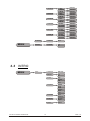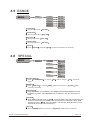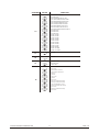
1
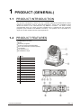
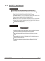
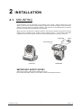
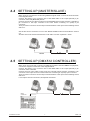
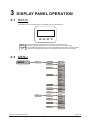
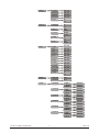
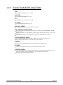
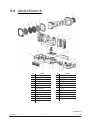
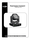
LED MOVING WASH
USER
MANUAL
Ver 1,0
T
ABLE OF CONTENTS
PART 1 PRODUCT (GENERAL)................................................................. 1.
1.1--PRODUCT INTRODUCTION........................................................................1.
1.2--PRODUCT FEATURES................................................................................1.
1.3--TECHNICAL SPECIFICATIONS................................................................... 2.
1.4--PHOTOMETRIC DATA.................................................................................3.
1.5--SAFETY WARNING.....................................................................................4.
PART 2 INSTALLATION ........................................................................... 5.
2.1-- MOUNTING ................................................................................................5.
2.2-- FUSE REPLACEMENT............................................................................... 6.
2.3-- SETTING UP (STAND ALONE).................................................................... 6.
2.4-- SETTING UP (MASTER/SLAVE).................................................................. 7.
2.5-- SETTING UP (DMX512 CONTROLLER)....................................................... 7.
PART 3 DISPLAY PANEL OPERATION....................................................... 8.
3.1--BASIC........................................................................................................8.
3.2--MENU........................................................................................................ 8.
3.3-- INTRO ....................................................................................................... 10.
3.4-- INVERT ......................................................................................................11.
3.5-- RANGE ......................................................................................................12.
3.6-- SPECIAL ................................................................................................... 12.
3.7-- EDIT ..........................................................................................................13.
3.8-- EXTRA .......................................................................................................13.
3.9-- CALIB ....................................................................................................... 14.
3.10-- CODECHANGE ....................................................................................... 15.
3.11--DEFAULT ................................................................................................ 15.
PART 4 USING A DMX512 CONTROLLER...................................................16.
4.1--BASIC ADDRESSING................................................................................. 16.
4.2--CHANNEL ASSIGNMENT............................................................................ 16.
4.3--BASIC INSTRUCTIONS FOR DMX512 OPERATION .................................... 19.
PART 5 APPENDIX................................................................................... 20.
5.1-- TROUBLE SHOOTING................................................................................ 20.
5.2-- MAINTENANCE .......................................................................................... 21.
1
PRODUCT (GENERAL)
1.1
PRODUCT INTRODUCTION
This product is designed for indoor use only. Suitable applications include wash or effect
lighting for architectural, stage or nightclub applications. Direct input of DMX512 signal
allows the fixtures to be controlled from any DMX512 controller. The fixture is fully
programmable with one custom program available and is supplied with two automatic
programs (all accessible from DMX512 controller). This product can be operated as a
single unit or with multiple units for large applications.
1.2
PRODUCT FEATURES
RGBW Dimmer 0-100%
Strobe
Automatic programs
Custom program (programmable)
Auto-color sequence (variable speed)
LCD display
Fan speed control
DirectDMX512 input
No
ITEM
1
Head
2
Side arm
3
Handle
4
Menu
5
Enter
6
Down
7
Up
8
Switch
9
Power input
10
DMX 5-PIN signal input
11
DMX 3-PIN signal input
12
DMX 3-PIN signal output
13
DMX 5-PIN signal output
14
Safety lock
1 PRODUCT(GENERAL)
1
2008.7.31
1.3
TECHNICAL SPECIFICATIONS
Voltage
Rated Power
LED/Unit
100~240V...50/60Hz
280W
54pcs (14 X 2W RED / 14 X 3W GREEN
/ 14 X 3W BLUE/12 X 3W WHITE)
Cooling
Dimensions
Weight
1 PRODUCT(GENERAL)
Forced air convection
390 x 320 x 385mm
16Kg
2
2008.7.31
1.4
PHOTOMETRIC DATA
WHITE
6300
1550
694
404
2
4
6
8
5140
1373
620
350
2
4
6
8
9360
2320
1055
602
2
4
6
8
1710
420
192
110
2
4
6
8
16050
3920
1765
1010
2
4
6
8
20200
5400
2430
1400
2
4
6
8
277 LUX
15
3
2
1
0
1
2
3
10Distance(m)
RED
238 LUX
15
3
2
1
0
1
2
3
10Distance(m)
GREEN
398 LUX
15
3
2
1
0
1
2
3
10Distance(m)
BLUE
73 LUX
15
3
2
1
0
1
2
3
10Distance(m)
RGB
670 LUX
15
3
2
1
0
1
2
3
10Distance(m)
RGB+WHITE
1 PRODUCT(GENERAL)
950 LUX
15
3
2
1
0
1
2
3
3
10Distance(m)
2008.7.31
1.5
SAFETY WARNING
IMPORTANT
ALWAYS READ THE USER MANUAL BEFORE OPERATION.
PLEASE CONFIRM THAT THE POWER SUPPLY STATED ON THE
PRODUCT IS THE SAME AS THE MAINS POWER SUPPLY IN YOUR AREA.
This product must be installed by a qualified professional.
Always operate the equipment as described in the user manual.
A minimum distance of 0.5m must be maintained between the equipment and
combustible surface.
The product must always be placed in a well ventilated area.
Always make sure that the equipment is installed securely.
DO NOT stand close to the equipment and stare directly into the LED light
source.
Always disconnect the power supply before attempting and maintenance.
Always make sure that the supporting structure is solid and can support the
combined weight of the products.
The earth wire must always be connected to the ground.
Do not touch the power cables if your hands are wet.
ATTENTION
This product left the place of manufacture in perfect condition. In order to
maintain this condition and for safe operation, the user must always follow the
instructions and safety warnings described in this user manual.
Avoid shaking or strong impacts to any part of the equipment.
Make sure that all parts of the equipment are kept clean and free of dust.
Always make sure that the power connections are connected correct and
secure.
If there is any malfunction of the equipment, contact your distributor
immediately.
When transferring the product, it is advisable to use the original packaging in
which the product left the factory.
Shields, lenses or ultraviolet screens shall be changed if they have become
damaged to such an extent that their effectiveness is impaired.
The lamp (LED) shall be changed if it has become damaged or thermally
deformed.
1 PRODUCT(GENERAL)
4
2008.7.31
2
2.1
INSTALLATION
MOUNTING
The LED fixture can be operated in any position at any angle. When mounted on a flat
surface, the surface must be strong enough to support 10 times the weight of the fixture and
stable so that the will be no damage caused to the fixture or surrounding people or objects
because of movements of the fixture on the surface.
When the unit is mounted in a hanging position, the fixture is attached using the mounting
brackets and a standard truss clamp or other clamping device. The mounting brackets
supplied are mounted using quick-release locks allowing simple mounting or removal.
HANGING
UPRIGHT
IMPORTANT SAFETY NOTE!!
Always use a safety cable when installing this unit!!
Be sure that the safety cable is connected to a solid load-bearing structure.
2 INSTALLATION
5
2008.7.31
2.2
FUSE REPLACEMENT
Remove the safety cap by a screwdriver.
F etch the old fuse from safety cap.
I nstall a new fuse.
I nstall the safety cap.
Safety Cap
Fuse
2.3
SETTING UP (STAND ALONE)
The LED fixture can be used as a stand alone unit. The stand alone functions AUTO 1,
AUTO 2, CUSTOM can be activated without the need to connect to any controller or
connecting to any other equipment.
Simply, access the <operation> menu from the DISPLAY and select the target program to
activate.
2 INSTALLATION
6
2008.7.31
2.4
SETTING UP (MASTER/SLAVE)
When units are connected in series using DMX512 signal cable connect the units as shown
in the diagram below
Connect the (male) 3 pin connector side of the DMX cable to the output (female) 3 pin
connector of the first (MASTER) fixture.
Connect the end of the cable coming from the MASTER fixture which will have a (female) 3
pin connector to the input connector of the next fixture consisting of a (male) 3 pin
connector.
Then proceed to connect from the output as stated above to the input of the following fixture
and so on.
Set the first unit in the series to one of the STAND ALONE modes as described in section
2.2
All other units in the series should be set to <SLAVE> from the <operation> menu.
MASTER
2.5
SLAVE
SLAVE
SETTING UP (DMX512 CONTROLLER)
When units are connected in series to a DMX512 controller and other DMX512 equipment,
connect the equipment as shown in the diagram below.
Connect the (male) 3 pin connector side of the DMX cable to the output (female) 3 pin
connector of the controller.
Connect the end of the cable coming from the controller which will have a (female) 3 pin
connector to the input connector of the next fixture consisting of a (male) 3 pin connector.
Then proceed to connect from the output as stated above to the input of the following fixture
and so on.
If over 32pcs fixtures connected ,the amplifier is needed.
DMX512
CONTROLLER
2 INSTALLATION
7
2008.7.31
3
3.1
DISPLAY PANEL OPERATION
BASIC
The LED fixture is mounted with a LCD display and 4 control buttons.
MENU
ENTER
DOWN
UP
MENU Scroll through the main menu or exit from the current sub-menu
ENTER Enter the currently selected menu or confirm the current function value
DOWN Scroll 'DOWN' through the menu list or decrease the value of the current function
UP
Scroll 'UP' through the menu list or increase the value of the current function
3.2
MENU
MENU
1 Intro
1.1 Address
(001~512)
1.2 Reset
Yes
No
1.3 Fans
High
Normal
Low
Auto
1.4 Operation
DMX512
Auto1
Auto2
Custom
Slave
Test
1.5 Channels
Basic
Advanced
2 Invert
1.6 Display
60 close
Bright
1.7 Info
Edition
2.1 Pan
Normal
Reverse
2.2 Tilt
Normal
Reverse
2.3 Dimmer
Normal
Reverse
2.4 Use
No
Yes
3 DISPLAY PANEL OPERATION
8
2008.7.31
3 Range
3.1P/start
(000~255)
3.2P/Finish
(000~255)
3.3T/start
(000~255)
3.4T/Finish
(000~255)
3.5 Use
No
Yes
4 Special
4.1 BlackDelay
No
4.2Reset
DMX
Yes
System
4.3 Dimmer
Normal
Special
4.4 RGB
No
Yes
4.5 Fan
DMX
System
5 EDIT
6 Extra
7 Calib
3 DISPLAY PANEL OPERATION
9
5.1STEP
(001~255)
5.2pan
(000~255)
5.3tilt
(000~255)
5.4speed
(000~255)
5.5 red
(000~255)
5.6 green
(000~255)
5.7 blue
(000~255)
5.8 white
(000~255)
5.9 strobe
(000~255)
5.10 dim-speed
(000~255)
5.11 time
(000~255)
5.12 Use
No
Yes
6.1User-key
0000
6.2password
0000
7.1 W1:3200K
7.1 RED
7.1 GREEN
7.1 BLUE
(000~255)
(000~255)
(000~255)
7.2 W2:3400K
7.2 RED
7.2 GREEN
7.2 BLUE
(000~255)
(000~255)
(000~255)
7.3 W3:4200K
7.3 RED
7.3 GREEN
7.3 BLUE
(000~255)
(000~255)
(000~255)
7.4 W4:4900K
7.4 RED
7.4 GREEN
7.4 BLUE
(000~255)
(000~255)
(000~255)
7.5 W5:5600K
7.5 RED
7.5 GREEN
7.5 BLUE
(000~255)
(000~255)
(000~255)
7.6 W6:5900K
7.6 RED
7.6 GREEN
7.6 BLUE
(000~255)
(000~255)
(000~255)
2008.7.31
MENU
3.3
7.7 W7:6500K
7.7 RED
7.7 GREEN
7.7 BLUE
(000~255)
(000~255)
(000~255)
7.8 W8:7200K
7.8 RED
7.8 GREEN
7.8 BLUE
(000~255)
(000~255)
(000~255)
7.9 W9:8000K
7.9 RED
7.9 GREEN
7.9 BLUE
(000~255)
(000~255)
(000~255)
7.10 W10:8500K
7.10 RED
7.10 GREEN
7.10 BLUE
(000~255)
(000~255)
(000~255)
7.11 W11:10000K
7.11 RED
7.11 GREEN
7.11 BLUE
(000~255)
(000~255)
(000~255)
7.12 RGB W
7.12 RED
7.12 GREEN
7.12 BLUE
(000~255)
(000~255)
(000~255)
8 CodeChange
8.1 User-key
0000
10 Default
10.1 Default
Yes
No
1 Intro
1.1 Address
(001~512)
1.2 Reset
Yes
No
1.3 Fans
High
INTRO
MENU
Normal
Low
Auto
1.4 Operation
DMX512
Auto1
Auto2
Custom
Slave
Test
1.5 Channels
Basic
Advanced
3 DISPLAY PANEL OPERATION
10
1.6 Display
60 close
Bright
1.7 Info
Edition
2008.7.31
1.1 Address
Enter 1.1 Address
to set the DMX Address, which is from (001-512)
1.2 Reset
In order to rest custom modest to default, select
1.2 Reset
1.3 Fans
Enter 1.3 Fans to select the working mode of fan:
Normal is for normal; Low is for slow ; Auto
1.4 Operation
Enter 1.4 Operation to select the operation mode:
Auto2 ; Custom ; Slave ; Test
1.5 Channels
Enter 1.5 Channels
1.6 Display
Enter 1.6 Display
1.7 Info
Enter 1.7 Info
3.4
High is for fast;
is for Auto
DMAX512 ;
to select the DMX channel modes: Basic ;
Auto1 ;
Advanced .
to select the lighting time of the LCD display panel.
to see the version of the software.
INVERT
MENU
2.1 Pan
2 Invert
Normal
Reverse
2.2 Tilt
Normal
Reverse
2.3 Dimmer
Normal
Reverse
2.4 Use
No
Yes
2 Invert
Select 2.1 Pan / 2.2 Tilt / 2.3 Dimmer to set Normal
Enter 2.4 Use and set Yes to run the new setting
3 DISPLAY PANEL OPERATION
11
or
Reverse
2008.7.31
3.5 RANGE
MENU
3 Range
3.1P/start
(000~255)
3.2P/Finish
(000~255)
3.3T/start
(000~255)
3.4T/Finish
(000~255)
3.5 Use
No
Yes
3.1P/start
Set pan start value
3.2P/Finish
Set pan finish value
3.3T/start
Set Tilt start value
3.4T/Finish
Set Tilt finish value
3.5 Use
Enter 3.5 Use
3.6
000~255
000~255
000~255
000~255
and select Yes to open the operation of X/Y angle
SPECIAL
MENU
4.1 BlackDelay
4 Special
No
Yes
DMX
4.2Reset
System
Normal
4.3 Dimmer
Special
4.4 RGB
No
4.5 Fan
DMX
Yes
System
4.1 BlackDelay
Enter 4.1 BlackDelay
delay
to choose
4.2Reset
Enter 4.2Reset to choose DMX
cannot control reset
No
without delay or
DMX control reset or
Yes
3seconds
System
DMX
4.3 Dimmer
When DIMMER is set to NORMAL, then RGBW and MASTER DIMMER are linear
CURRENT Vs. DMX. When DIMMER is set to SPECIAL, then the dimming is not
linear
4.4 RGB
When RGB TO WHITE is set to Yes , then when RGB = 255,255,255 then the color
is perfect white as the actual RGB values are adjusted to make white. When RGB
TO WHITE is set to No , then when RGB = 255,255,255, the RGB values are not
adjusted and the output is most powerful
4.5 Fan
C hoose DMX DMX to control fan or
3 DISPLAY PANEL OPERATION
12
System
DMX cannot control fan
2008.7.31
3.7
EDIT
MENU
5 EDIT
5.1STEP
(001~255)
5.2pan
(000~255)
5.3tilt
(000~255)
5.4speed
(000~255)
5.5 red
(000~255)
5.6 green
(000~255)
5.7 blue
(000~255)
5.8 white
(000~255)
5.9 strobe
(000~255)
5.10 dim-speed
(000~255)
5.11 time
(000~255)
5.12 Use
No
Yes
5 EDIT
Enter the 5 EDIT mode to edit the custom programs by adjusting the
value of 5.1STEP , 5.2pan , 5.3tilt , 5.4speed , 5.5 red , 5.6 green ,
5.7 blue , 5.8 white , 5.9 strobe , 5.10 dim-speed , 5.11 time
Enter 5.12 Use and select Yes to run the steps user need.
Note: if user want to circulate the created steps, please set the last step
5.11 time as 0
For example, there are 3 steps, the
Ste p 1
5.11 time
Ste p 2
5.11 time
Ste p 3
5.11 time
3.8
s
setting should be like belowed:
=4
5.12 Use = Yes
=5
5.12 Use = Yes
=0
5.12 Use = Yes
EXTRA
MENU
6 Extra
6.1User-key
0000
6.2password
1111
6.1User-key
When the user inputs 6.1User-key ,the hidden menu 7 Cablid ,
8 CodeChange , 9 default will appear on display panel, and the user is
able to reset the DEFAULT values of all functions.
The User-keey can be changed at
0000 .
8 codechange , the default access code is
6.2password
When the user inputs the
6.2password ,the user is able to reset the DEFAULT
values and get the administrator rights The password can be changed at
8 CodeChange , the default access code is 1111
3 DISPLAY PANEL OPERATION
13
2008.7.31
3.9
CALIB
MENU
7 Calib
7.1 W1:3200K
7.1 RED
7.1 GREEN
7.1 BLUE
(000~255)
(000~255)
(000~255)
7.2 W2:3400K
7.2 RED
7.2 GREEN
7.2 BLUE
(000~255)
(000~255)
(000~255)
7.3 W3:4200K
7.3 RED
7.3 GREEN
7.3 BLUE
(000~255)
(000~255)
(000~255)
7.4 W4:4900K
7.4 RED
7.4 GREEN
7.4 BLUE
(000~255)
(000~255)
(000~255)
7.5 W5:5600K
7.5 RED
7.5 GREEN
7.5 BLUE
(000~255)
(000~255)
(000~255)
7.6 W6:5900K
7.6 RED
7.6 GREEN
7.6 BLUE
(000~255)
(000~255)
(000~255)
7.7 W7:6500K
7.7 RED
7.7 GREEN
7.7 BLUE
(000~255)
(000~255)
(000~255)
7.8 W8:7200K
7.8 RED
7.8 GREEN
7.8 BLUE
(000~255)
(000~255)
(000~255)
7.9 W9:8000K
7.9 RED
7.9 GREEN
7.9 BLUE
(000~255)
(000~255)
(000~255)
7.10 W10:8500K
7.10 RED
7.10 GREEN
7.10 BLUE
(000~255)
(000~255)
(000~255)
7.11 W11:10000K
7.11 RED
7.11 GREEN
7.11 BLUE
(000~255)
(000~255)
(000~255)
7.12 RGB W
7.12 RED
7.12 GREEN
7.12 BLUE
(000~255)
(000~255)
(000~255)
7 Calib
Enter the 7 Calib to select white color of different color temperature.
There are 11 pre-programmed White colors plus RGB TO WHITE and can be edited
by using Red , Green & Blue .
3 DISPLAY PANEL OPERATION
14
2008.7.31
3.10
CODECHANGE
MENU
8 CodeChange
8.1 User-key
****
8.2password
****
8 CodeChange
S elect 8.1 User-key to set the password
S elect 8.2 Password to set the password.
Note:
3.11
8.2 Password will not appear only when
6.2 password
is activated.
DEFAULT
MENU
9.1 Default
9 Default
Yes
No
9 Default
This functions will reset all setting to the original factory setting
3 DISPLAY PANEL OPERATION
15
2008.7.31
4
4.1
USING A DMX512 CONTROLLER
BASIC ADDRESSING
Connect all of the units in series using standard DMX512 signal cable .
Set the DMX512 address in the DMX menu.
It is possible to have the same DMX address or independent addresses for each fixture.
4.2
CHANNEL ASSIGNMENT
Note: This product have two DMX512 channel configuration:
ADVANCED
and
BASIC .
ADVANCED
CHANNEL
1
VALUE
FUNCTION
PAN
Clockwise rotate 0~54 0
0
255
0
255
0
255
0
255
Fine control of tilt movement 0~3
0
255
From fast to slow
0
255
0
255
0
255
PAN FINE
2
Fine control of pan movement 0~3
TILT
3
Anti-clockwise rotate 0~270
TILT FINE
4
PAN/TILT SPEED
5
RED
6
7
8
GREEN
BLUE
WHITE
9
4 USING A DMX512 CONTROLLER
0
255
16
2008.7.31
CHANNEL
VALUE
FUNCTION
COLOR/WHITE MACRO
10
0
5
NO FUNCTION
6
25
RED UP/GREEN 0%/BLUE 100%
26
45
RED 100%/GREEN UP/BLUE DOWN
46
65
RED DOWN/GREEN 100%/BLUE 0%
66
85
RED 0%/GREEN DOWN/BLUE UP
86
105
RED UP/GREEN 0%/BLUE DOWN
106
125
RED DOWN /GREEN UP/BLUE 0%
126
145
RED UP / GREEN 100% / BLUE 0%
146
165
RED DOWN / GREEN DOWN/ BLUE UP
166
180
NO FUNCTION
181
190
NO FUNCTION
191
200
NO FUNCTION
201
205
WHITE 1:3200K
206
210
WHITE 2:3400K
211
215
WHITE 3:4200K
216
220
WHITE 4:4900K
221
225
WHITE 5:5600K
226
230
WHITE 6:5900K
231
235
WHITE 7:6500K
236
240
WHITE 8:7200K
241
245
WHITE 9:8000K
246
250
WHITE 10: 8500K
251
255
WHITE 11: 10000K
0
255
0
255
0
5
NO FUNCTION
6
255
Fast to Slow
0
19
No function
20
39
Pan/tilt black activated
40
59
Pan/tilt black deactivated
60
79
Fan auto
80
99
Fan slow
100
119
Fan normal
120
139
Fan fast
140
149
No function
150
159
Auto1 (activated after 3 secs)
160
169
Auto2 (activated after 3 secs)
170
179
Test (activated after 3 secs)
180
189
Custom (activated after 3 secs)
190
199
No function
200
219
Reset (activated after 3 secs)
220
255
No function
DIMMER
11
12
STROBE
DIMMER SPEED
13
CONTROL
14
4 USING A DMX512 CONTROLLER
17
2008.7.31
BASIC
CHANNEL
1
VALUE
FUNCTION
PAN
Clockwise rotate 0~54 0
0
255
0
255
0
255
0
255
0
255
0
255
0
5
NO FUNCTION
6
25
RED UP/GREEN 0%/BLUE 100%
26
45
RED 100%/GREEN UP/BLUE DOWN
46
65
RED DOWN/GREEN 100%/BLUE 0%
66
85
RED 0%/GREEN DOWN/BLUE UP
86
105
RED UP/GREEN 0%/BLUE DOWN
106
125
RED DOWN /GREEN UP/BLUE 0%
126
145
RED UP / GREEN 100% / BLUE 0%
146
165
RED DOWN / GREEN DOWN/ BLUE UP
166
180
NO FUNCTION
181
190
NO FUNCTION
191
200
NO FUNCTION
201
205
WHITE 1:3200K
206
210
WHITE 2:3400K
211
215
WHITE 3:4200K
216
220
WHITE 4:4900K
221
225
WHITE 5:5600K
226
230
WHITE 6:5900K
231
235
WHITE 7:6500K
236
240
WHITE 8:7200K
241
245
WHITE 9:8000K
246
250
WHITE 10: 8500K
251
255
WHITE 11: 10000K
0
255
0
255
0
19
No function
20
39
Pan/tilt black activated
40
59
Pan/tilt black deactivated
60
79
Fan auto
80
99
Fan slow
100
119
Fan normal
120
139
Fan fast
140
149
No function
150
159
Auto1 (activated after 3 secs)
160
169
Auto2 (activated after 3 secs)
170
179
Test (activated after 3 secs)
180
189
Custom (activated after 3 secs)
190
199
No function
200
219
Reset (activated after 3 secs)
220
255
No function
TILT
2
3
Anti-clockwise rotate 0~270
RED
GREEN
4
5
6
BLUE
WHITE
COLOR/WHITE MACRO
7
8
9
DIMMER
STROBE
CONTROL
10
4 USING A DMX512 CONTROLLER
18
2008.7.31
4.3
FUNCTION EXPLANATION
PAN
CH1 adjusts the PAN from 0
to 540
PAN FINE
CH2 adjusts the PAN from 0
to 3
TILT
CH3 adjusts the TILT from 0
to 270
TILT FINE
CH4 adjusts the TILT from 0
to 3
PAN/TILT SPEED
CH5 adjusts the speed of the PAN and TILT faders
RED, GREEN , BLUE & WHITE
CH6, CH7,CH8 & CH9 control the intensity of each of the RED, GREEN , BLUE &
WHITE LEDs.
When the slider is at the highest position (255) the intensity of the color is the
maximum
CH6, CH7,CH8 & CH9 can be combined together to create millions of colors.
COLOR MACRO & WHITE
The COLOR MACRO allows the user to select from a linear range of colors
When the slider is at the top of the slider the color is WHITE
DIMMER
CH11 is an overall DIMMER for the currently selected / created color
STROBE
CH12 is the strobe channel and controls the speed of the strobe.
CONTROL MODE
CH14 allows the user to select special function Pan/Tilt blackout open/close, Fan
setting, the preset auto program Auto 01-02, test and custom program.
CH 14 can be used to reset the fixture.
4 USING A DMX512 CONTROLLER
19
2008.7.31
5
APPENDIX
5.1
TROUBLE SHOOTING
SITUATION
CAUSE
ACTION
PART ORDER NUMBER
Power connection error
Check all power connections
Power switch damaged
Replace power switch
16-03-0042-00
Display board damaged
Replace display board
26-2A-2107CDI4-00
LED MODULE on,
but no control
Display board damaged
from display
Replace display board
26-2A-2107CDI4-00
LED PCB damaged
Replace PCB board
26-2A-603LED3-00
MAIN PCB damaged
Replace main PCB board
26-2A-LED603POWER-00
LED module on,
LEDs of all colors MAIN PCB damaged
are not lit
Replace main PCB board
26-2A-LED603POWER-00
No display
LEDs of the same
color are not lit
Display normal,
but no response
to DMX 512
controller
Signal connection error
Check and replace signal cable
DMX Address error
Check and reset DMX address
Fan error
Replace fan
16-00-0043-00
Fan actiyator
Replace fan actiyator
26-2A-LED603FAPOWER-00
Sensor PCB error
Replace sensor PCB
26-2A-1250HL-00
Optical sensor PCB error
Replace optical sensor PCB 34-01-LED603_010-A0
Cable of motor damaged
Replace cable of motor
Fan do not work
Pan/Tilt
cannot reset
Pan/Tilt motor
do not work
Main PCB damaged
5 APPENDIX
Replace Tilt motor
15-00-0105-00
Replace pan motor
15-00-0106-00
Replace main PCB board
26-2A-LED603POWER-00
Motor damaged
20
2008.7.31
5.2
MAINTENANCE
No
ITEM
No
1
Plastic front cover
14
Base upper cover 1
2
Lens upper cover
15
DMX board
3
Lens
16
Side coverB
4
Lens base cover
17
Handle
5
LED board
18
Power socket
6
LED board supporting base
19
Fuse
7
Heat-transfer plate
20
Switch
8
Plastic head cover
21
Base bottom cover
Power supply
ITEM
Back cover for head
22
10
U bracket
23
Base upper cover 2
11
9
Driver board
24
Side cover A
12
Arm cover
25
Display Board
13
XY control board
Version 1.0
5 APPENDIX
21
2008.7.31