1
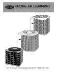
Owner's Manual
USER'S INFORMATION
MANUAL FOR THE OPERATION AND
MAINTENANCE
OF YOUR NEW RESIDENTIAL
HEAT PUMP
Safety Considerations
Recognize
safety inform;ttion,
This is the safety-alert
symbol
_,
When you see this symbol
(511the unit and ill instrtlctions
(51
manuals, be alert to the potential l\sr personal injury.
Understand the signal words DANGER, WARNING, and CAUTION. These words are used with the safety-alert symbol. DANGER
identifies the most serious hazards which will result in severe personal injury or death. WARNING signifies hazards which could
result in personal injury or death. CAUTION is used to identify unsafe practices which may result in minor personal injury or product
and property damage. NOTE is used to highlight suggestions which will result in enhanced installation, reliability, or operation.
WARNING: ELECTRICAL SHOCK, FIRE, EXPLOSION, PERSONAL INJURY HAZARD
Improper installation, adjustment, alteration, service, maintenance or use could result in personal injury, death,
and/or property damage.
Consult a qualified installer, service agency, or your distributor or branch for information or assistance. The
qualified installer or agency must use factory-authorized
kits or accessories when modifying this product.
A WARNING: ELECTRICAL SHOCK, UNIT OPERATION AND SAFETY HAZARD
Failure to follow this warning could result in personal injury, death, and/or property damage.
Read and follow all instructions
and warnings,
including labels shipped with or attached to unit before
ing your new heat pump.
IMPORTANT
To better
protect
operat-
FACTS
your
investment
and to eliminate
unnecessary
service
calls,
• Your heat pump system should never be operated without a clean air filter properly
clogged air filter will increase operating costs and shorten the life of the unit,
• Supply-air and return-air registers should not be blocked. Drapes, furniture,
ing grilles. Restricted airflow lessens the unit's efficiency and life span,
familiarize
yourself
with the following
facts:
installed. Plan to inspect the filter periodically.
and toys are some of the items commonly
A
found obstruct-
• The outdoor unit must have unrestricted airflow, Do not cover the unit, lean anything against it, or stand upon it, Do not allow grass
clippings, leaves, or other debris to accumulate around or on top of the unit, Maintain a 12-in, minimum clearance between the
outdoor unit and tall grass, vines, shrubs, etc,
• Your multipuq?ose indoor thermostat is the control center for your heat pump system.You should lhmiliarize yourself with its proper
operation, Attempting to control the system by other means--for
instance, switching the electrical supply power ON and OFF--may
cause damage to the unit.
• During heating, increasing the thermostat more than 2 degrees may cause the supplemental
thermostat, Needless use of the supplementary
heat reduces potential enelgy savings.
heaters to be turned on to satisfy the
• You may find that you can maintain grexLter personal comfort by running the fan continuously. Air pockets can fon_n due to the structure
of the house, placement of registers, etc. These air pockets may be too cool or wan_n for your liking. Continuous lhn operation minimizes
any temperature differences. Also, systems equipped with electronic air clexmers and/or humidifiers offer the added benefits of having the
air continuously cleaned year-round, and humidified during the winter season,
• Your heat pump will remove humidity from your home during the cooling season, After a few minutes of operation, you should be
able to see water trickle from the condensate drain of the indoor cooling coil, Check this occasionally to be sure the drain system is
not clogged. Of course, don't expect to see much drainage if you live in a very dry environment,
NOTE TO INSTALLER:
THIS MANUAL
MUST BE LEFT WITH THE EQUIPMENT
USER.
• During the heating cycle, air from your registers may seem cool. This is because the air is being delivered at a higher velocity and a
more constant flow than air supplied by a conventional furnace. Also, your heat pump supplies air at 90 ° to 105°F instead of in sudden
bursts of hot air as with a conventional furnace. The air may feel cool because it is slightly lower than your body temperature.
However. it is sufficiently warm to keep you comfortable.
• Ice or frost will tend to form on the outdoor coil during the winter heating operation.Your heat pump is designed to automatically
melt the ice. When in this defrost cycle, it is normal l_r steam or l_g to rise from the outdoor unit. Do not be alarmed!
OPERATING
YOUR HEAT PUMP
The operation of your heat pump system is controlled by the indoor thermostat. You simply adjust the thermostat and it maintains
the indoor temperature at the level you select. Refer to the thermostat operating instructions l\_r inl\_rmation on how to operate your
thermostat.
COOLING
CYCLE
When operating in the cooling mode, your heat pump will l_l.lnnntil the indoor temperature
is lowered to the level you have selected.
On extremely hot days, your heat pump will run for longer periods at a time and have shorter off periods than on moderate days.
Lowering the setpoint of your thermostat
will not cause your heat pump to cool lhstel:
The following are typical conditions that add extra heat and/or humidity
your home comf_rtable
under these conditions:
• Entrance
doors are frequently
• Laundry appliances
to your home. Your cooling
unit will work longer to keep
opened and closed
are being operated
• A shower is running
• More than the usual number of people are present in the home
• More than the normal
number of electric lights are in use
• Drapes are open on the sunny side of the home
HEATING
CYCLE
With HEAT selected, the heating section of your home comfort system will operate until roolll temperature is raised to the level you
have selected. Of course, the heating unit will have to operate l\_r longer periods to maintain a coml\)rtable environment on cooler
days and nights than on moderate ones.
DEFROST
CYCLE
When your heat pump is providing heat to your home and the outdoor temperature
drops below 45°F, moisture may begin to freeze
on the surface of the outdoor coil. If allowed to build up, this ice would impede airflow across the coil and reduce the amount of heat
absorbed from the outside all: So, to maintain energy-efficient
operation, your heat pump has an automatic defrost cycle.
The defrost cycle starts at a preset time interval of 90 minutes, although, it may be reset to either 30 or 60 minutes.
at the preset time only if the ice is sufficient to interfere with normal heating operation.
After the ice is melted from the outdoor
back to normal heating operation.
coil, or alter a maximum
Do not be alarmed if steam or fog appears at the outdoor
into a mist in the cold outside all;
Defrost
will start
of 10 minutes in the defrost mode, the unit will automatically
unit during the defrost cycle. Water vapor from the melting
ice may condense
During certain weather conditions such as heavy snow and freezing rain it is not uncommon
for ice to build up on the outdoor
grille. This is normal l\_r these weather conditions. Do not attempt to remove the ice from the outdoor unit grille. This condition
not affect the proper function of the unit and will clear within a few days.
EMERGENCY
unit
will
HEAT
The EMERGENCY
HEAT setting on your thermostat
home coml\_rt system. Operation of the EMERGENCY
the heat pump, or if the heat pump malfunctions.
refers to any supplementary
heating appliance that may be included in your
HEAT source may be required if heating demands exceed the capacity of
During the heating season, switch to EMERGENCY
HEAT
minutes for any reason (i.e., power outage). Leave the switch
during which the power was off: It isn't necessary to exceed
leave the switch in the EMERGENCY
HEAT position for 8
NOTE:
switch
The EMERGENCY
HEAT switch is effective
if the electricity to your outdoor unit has been off f_r more than 30
in the EMERGENCY
HEAT mode f_r an amount of time equal to that
12 hours. If you cannot determine how long the power has been off,
hours.
only when HEAT or AUTO is selected.
PERFORMING
ROUTINE
MAINTENANCE
With the proper maintenance and care, your heat pump unit will operate economically
and dependaMy. Maintenance
can be accomplished easily by referring to the following directions. However, bef_le performing
maintenance,
consider these important safety
precautions.
WARNING: ELECTRICAL SHOCK HAZARD
Failure to follow this warning could result in personal injury, death.
Disconnect all electrical power to the heat pump before removing access panels to perform maintenance. Disconnect power to both the indoor and outdoor units. Note: There may be more than 1 electrical disconnect switch.
CAUTION: CUT HAZARD
Failure to follow this caution may result in personal injury.
Although special care has been taken to minimize sharp edges in the construction of your unit. Be extremely careful
when handling parts or reaching into the unit. Use care and wear appropriate protective clothing and gloves when
handling parts.
CHECKTHE
AIR FILTER
A dirty air filter will cause excessive straiu ou the conlpressor aud blower nlotor. This cau cause the compoueuts
to overheat aud
automatically shut down. In the extreme, the components will fail and need to be replaced. To avoid inefficient or failed operation
of your unit, CHECK THE FILTER(S) EVERY 3 TO 4 WEEKS. Replace filter(s) when necessary, or clean the filter(s) if you have
the washaMe type.
Disposable filters should be replaced by silnilal: new filters of the same dimensions.
Reusable, washable filters should be washed in a solution of cold water and mild detergent, then rinsed and thoroughly dried. THE
FILTER MUST BE COMPLETELY DRY BEFORE BEING REINSTALLED. To avoid prolonged shutdown of your unit while a
filter is drying, you should have an extra filter on hand. This would allow you to rotate between the two filters with minimal downtime
f_r your coml\_rt system. Extra filters may be purchased
from your dealel:
There are no filters in the outdoor unit of a split system. If your indoor unit is a gas or oil furnace, refer to your furnace User's Manual
f_r filter location and procedures for replacement or cleaning.
If your system includes an indoor fan coil unit, the filter may be located in the unit where it connects with the return-air duct or plenum.
(See Fig. 1.) Remove the filter cover plate by sliding latches toward center of plate. Lift filter to clear lower flange. Filter is springloaded and will pop out. Reinstall filter, being certain to secure filter behind lower flange. When reinstalling cover plate, secure plate
behind upper flange then slide tabs outward.
\\
\
Fig. 1--Removing
Filter
from Fan Coil Unit
The indoor tim coil unit may be located
filter by removing the return air grille.
in the attic. In this instance
the filter may be located behind
the return air grille. Access
the
BEFORE YOU REQUEST
BEFORE
A SERVICE
YOU CALL FOR SERVICE,
CALL
CHECK
• Check the iudoor aud outdoor discouuect switches.
Verify
FOR THESE
EASILY SOLVED PROBLEMS:
that circuit breakers are ON or that fuses have uot blowu.
• Check f_ir sufficient airflow. Check the air filter(s) for any accumulations
sure grilles are opeu aud uuobstructed.
of dirt, Check f_ir blocked return-air
or supply-air
grilles. Be
• Check the settings on your indoor thermostat. If you desire cooling, see that the temperature setting is set below room temperature and COOL or AUTO is selected. If you require warmth, be sure the temperature setting is set above room temperature and
HEAT or AUTO is selected. The FAN switch should be set at ON l\_r continuous blower operation or AUTO if you wish the
blower to function only while the unit is operating.
If your comf_rt system still t_ailsto operate, coutact your serviciug dealer f_ir troubleshootiug
aud repairs. Specify your apparent
problem, and state the model aud serial lmmbers of your equiplnent. With this iuformation,
your dealer may be able to offer helpful
suggestions over the phoue or save valuable time through kuowledgeable
preparatioll l\_r the service call.
REGULAR
DEALER MAINTENANCE
In addition to the routine maintenance that you perform, your home comfort system should be inspected regularly by a properly
trained service technician. The inspection (preferably twice each year, but at least once every year) should include the f_llowing:
• Routine inspection ofair filter(s). Replacement orcleaning as required.
• Inspection and cleaning of the blower wheel, housing, and motor
as required.
• Inspection and, if required, cleaning of indoor and outdoor coils.
• Inspection of the indoor coil drain pan, plus the primary and secondary drain lines. If supplied, the auxiliary drain pan and line should
be inspected at this time. Service should include cleaning if required.
• A check ofall electrical wiring and connections.
• A check f_r secure physical connections of individual components within units.
• Operational check of the heat pump system to determine actual working condition. Necessary repair and/or adjustment should be
perf_rmed at this time.
Your servicing dealer may offer an economical service contract that covers seasonal inspections. Ask for further details.
FOR THE RECORD
Record the model, product, aud serial uumbers of your uew equipmeut. This illt\_rlnatiou,
facts requested, will be uecessary should you ever require ilfformatiou
or service.
© Payne Heating & Cooling Systems 7310 W. Morris St. Indianapolis,
IN 46231
Manufacturer
or designs without notice and obligations
reserves the right to change
at any time, specifications
Printed in U.S.A.
4
aloug
with the other ready-refereuce
edition date: 03/06
Catalog No, OG-PH 10-05
Replaces:
New