1
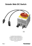
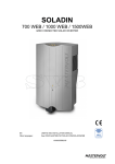
SOLADIN 700 WEB / 1000 WEB / 1500 WEB Grid connected solar inverter UK | USERS AND INSTALLATION MANUAL NL, DE, FR, compatible ES, IT : DOWNLOAD FROM WWW.MASTERVOLTSOLAR.COM/SOLADINWEB 10000005892/03 02 | EN / Soladin 700/1000/1500 Web User’s Manual EN / Soladin 700/1000/1500 Web User’s Manual | 03 1 2 11 3 4 5 6 7 8 9 10 1. Power LEDs (Section 6.4) 2. Cooling fan 3. WIFI LED (Section 6.4) 4. Status LED (Section 6.4) 5. AC connection compartment (Chapter 5) 6. WIFI connection button (Section 6.4) 7. WIFI antenna 8. DC plus input (Chapter 5) 9. DC minus input (Chapter 5) 10. Ground screw (Chapter 5) 11. Cooling outlet 04 | EN / Soladin 700/1000/1500 Web User’s Manual CONTENT 1 GENERAL INFORMATION 1.1 Product description 1.2 Use of this manual 1.3 Validity of this manual 1.4 Guarantee specifications 1.5Liability 1.6 Changes to the Soladin 1.7 Identification label 2 SAFETY GUIDELINES AND WARNINGS 2.1 Warnings and symbols 2.2 Use for intended purpose 2.3 Installation, maintenance, repair 2.4 Warning of special dangers 3HOW IT WORKS 3.1 Working principle of the Soladin 3.2 GRID CONNECTED INVERTER 3.3iSOLATED INVERTER 3.4 GRID INTERFACE 3.COMMUNICATION 4BEFORE YOU START 4.1UNPACKING 4.2 THINGS YOU NEED FOR INSTALLATION 4.3 INSTALLATION ENVIRONMENT 4.4 General safety and installation precautions 4.5 COUNTRY SUITABILITY 4.6 AC connection compartment 4.7 Specifications of the PV installation 4.8 Lightning protection 4.9 WI-FI ROUTER 5 INSTALLATION 5.1 Installation step by step 5.2 INSTALLATION OPTIONS 6 COMMISSIONING SET UP via Wi-fi 6.1 COUNTRY CODE SETTING 6.2 REGISTER TO INTELLIWEB 6.3DE-COMMISSIONING 6.4 LED TABLE 6.5 MANUAL REGISTRATION FOR INTELLIWEB 7 ADVANCED SETTINGS 7.1 ACCESSING INSTALLER SETTINGS 7.2 COUNTRY SETTINGS MENU 7.3 OPTIONS MENU 8 TROUBLE SHOOTING TABLE 9 Technical data 9.1 Technical specifications 9.2 SOLADIN WEB OUTLINE SETTINGS 9.3ordering information 10CERTIFICATES 10.1ec DECLARATION OF CONFORMITY 10.2 VDE V 0126-1-1 Unbedenklichkeitsbescheinigung 10.3 Konformitätsnachweis Eigenerzeugungseinheit 10.4 Konformitätsnachweis NA-Schutz 5 5 5 5 5 5 5 5 6 6 6 6 6 7 7 7 7 7 7 8 8 8 8 8 8 8 8 8 8 10 10 11 12 12 12 13 13 13 14 14 14 14 15 16 16 17 17 18 18 19 20 21 EN / Soladin 700/1000/1500 Web User’s Manual | 05 1 GENERAL INFORMATION 1.1 PRODUCT DESCRIPTION The Soladin 700 Web, 1000 Web and 1500 Web further referred to as “Soladin” or “Soladin Web” are grid connected solar inverters. This inverter type is used to convert photovoltaic power and feed this into the grid. The Soladin Web is not suitable for stand-alone use (i.e. use without utility grid). 1.2 USE OF THIS MANUAL Copyright © 2013 Mastervolt. All rights reserved. Reproduction, transfer, distribution or storage of part or all of the contents in this document in any form without the prior written permission of Mastervolt is prohibited. This manual serves as a guideline for the safe and effective use and installation of the Soladin: • For the installer this manual gives directions for the installation, operation and commissioning. • For the end user, this manual gives directions for the operation, maintenance and possible correction of minor malfunctions of this inverter. • Every person who works with the apparatus should be familiar with the contents of this manual, and must carefully follow the instructions contained herein. • Store the manual in an accessible place. Costs for installation labour or shipping of the defective parts are not covered by this warranty. For making an appeal on warranty you can contact your supplier directly, stating your complaint, application, date of purchase and part number / serial number. 1.5 LIABILITY Mastervolt accepts no liability for: • consequential damage due to use of the Soladin Web; • possible errors in the manuals and the results thereof. 1.6 CHANGES TO THE Soladin Changes to the Soladin Web inverter are not allowed. Changes to the Soladin Web software/ firmware, except for the settings made available to the user or installer, are not allowed. 1.7 IDENTIFICATION LABEL This manual is valid for the following models: Part number Model 130000700 Soladin 700 Web P/N: 130001500 Type: Soladin 1500 WEB 130001000 Soladin 1000 Web Input: 80-375Vdc, MPP 145-300Vdc, 12A 130001500 Soladin 1500 Web Output: 230Vac, 50Hz, 7.6A, 1500W, Cos phi 0.99 Soladin 1500 WEB P/N: S/N: C608A0678 130001500 70x50 mm Soladin 1500 WEB 1.3 VALIDITY OF THIS MANUAL 70x50 mm All the specifications, provisions andType: instructions Soladin 1500 WEB 80-375Vdc, MPP 145-300Vdc, 12A contained in this manual apply solelyInput: to the MastervoltFigure 1-1 Output: 230Vac, 7.6A, 1500W, Cos phi 0.99 SSID:50Hz, mastervolt-soladin-0678 delivered standard version of this inverter. S/N: C608A0678 Registration key: 1AF4 The identification label is positioned at the left side of the The scan code has no use for you. 1.4 SCOPE OF warranty IEC 62109-1, VDE 0126-1-1,Soladin. G83-1 4105, CEI 0-21, RD1663 IP21 SSID: mastervolt-soladin-0678 Mastervolt assures the product warranty of VDE the AR-N Soladin Registration key: 1AF4 Read this manual before installation and use, Web during five years after your purchase, on the Made in Thethis Netherlands condition that all instructions and warnings given in IEC 62109-1, VDE 0126-1-1, G83-1 VDE AR-N 4105, CEI 0-21, RD1663 IP21 This product has been declared conform manual are taken into account during installation and the EC directives and standards. operation. Made in Among other things, this means that installation is The Netherlands carried out by a qualified electrician, that installation and maintenance are executed according to the stated CAUTION! instructions and correct working sequence, and that no Never remove the identification label. changes or repairs may have been performed on the Soladin other than by Mastervolt. The warranty is limited to the costs of repair and/or replacement of the product by Mastervolt only. 06 | EN / Soladin 700/1000/1500 Web User’s Manual 2 SAFETY GUIDELINES AND WARNINGS 2.1 WARNINGS AND SYMBOLS Safety instructions and warnings are marked in this manual by the following pictograms: A procedure, circumstance, etc which deserves extra attention. CAUTION! Special information, commands and prohibitions in order to prevent damage. WARNING A WARNING refers to possible injury to the user or installer or significant material damage to the Soladin if the installer / user does not (carefully) follow the stated procedures. 2.3 INSTALLATION, MAINTENANCE, REPAIR WARNING As dangerous voltages exist, only allow installation, maintenance and repair of the Soladin Web to be carried out by qualified electricians. Connections and safety features must be executed according to the locally applicable regulations. In case of decommissioning and/or demounting follow the instructions as stated in this manual. If repairs or replacements are required, only use original Mastervolt spare parts. Make sure two persons are present when working on the installation, at least until the installation has been deenergized and verified by a suitable metering instrument. 2.4 WARNING OF SPECIAL DANGERS 2.2 USE FOR INTENDED PURPOSE The Soladin Web is constructed as per the applicable safetytechnical guidelines. Use the Soladin Web inverter only in installations that meet the following qualifications: • the electrical installation must meet the applicable regulations and standards (must be carried out correctly) and must be in a good condition; • according to the technical specifications. WARNING Two primary energy sources are present: • solar panels (DC) • utility grid (AC). Switch off both sources before starting any work on the installation. Block the switching device against unintentional reconnection. Verify the de-energizing of both DC and AC connections using a suitable metering instrument. Never use the Soladin Web in situations where there is danger of gas or dust explosion or potentially flammable products! The voltages present at the grid and solar side of the Soladin are not safe to touch. WArning Use of the inverter other than as mentioned under section 2.2 is considered to be conflicting with the intended purpose. In such cases, Mastervolt will not accept liability for any damage or injury caused by the functioning or malfunctioning of the inverter. 1 min Life danger caused by high electric voltages present at the connectors after disconnecting DC and AC. After 1 minute the connectors are voltage free. EN / Soladin 700/1000/1500 Web User’s Manual | 07 3 HOW IT WORKS The Soladin Web is a grid connected photovoltaic power inverter. It converts the high voltage DC power coming from the photovoltaïc (PV) panels into AC power. The AC power is fed back into the public utility grid, see figure 3-1. Solar input Output 230V AC + _ Soladin Web Grid Figure 3-1: Schematic example of the Soladin in a PV plant 3.1 Working principle of the Soladin 3.4 GRID INTERFACE PhotoVoltaïc (PV) modules convert light into DC power. A series of PV modules is called a string. The string must be connected to the solar input of the inverter. The PV string connected to the Soladin DC input is operated at its optimum voltage for an optimal yield (Maximum Power Point tracking). To reduce cable losses, PV modules are connected in series: a so-called “string”. A plane of PV modules is called a PV array and consists of multiple strings of the same length, being connected in parallel. The DC PV input is inverted to an AC output: 230V AC. For the PV input operating voltage range refer to the specifications. Selection of country settings is mandatory for use of the Soladin. Anti- islanding is provided according to national standards. The Soladin Web is not suitable to be operated in standalone mode (independently from the utility grid). The grid interface contains numerous safety mechanisms. 3.2 GRID CONNECTED INVERTER See figure 3-1. The Soladin Web main task is to convert DC power produced by the PV modules into AC power and to feed it back into the public utility grid. 3.3 ISOLATED inverter The Soladin Web is an isolated inverter. This isolated inverter has a High Frequency (HF) transformer inside which provides galvanic isolation between the DC (solar) and AC (grid) side. The Soladin is equipped with Isolation resistance detection: it monitors PV array isolation resistance. • Output relay to isolate the inverter form the grid. • DC injection: Monitors DC current injection into the grid. • Redundant grid voltage- and frequency monitoring • Anti islanding protection: loss of utility detection 3.5 Communication The Soladin Web configuration is communicated with your display via Wi-Fi. If you opt for online monitoring, the Soladin Web communicates with your internet router via Wi-Fi as well. 08 | EN / Soladin 700/1000/1500 Web User’s Manual 4BEFORE YOU START 4.1 UNPACKING In addition to the Soladin the delivery includes: • A mounting bracket to mount the Soladin to a wall • This Quick Install Guide • AC connection module. After unpacking, check the contents for possible damage. Do not use the product if it is damaged. If in doubt, contact your supplier. 4.2 THINGS YOU NEED FOR INSTALLATION Make sure you have all further parts to install the Soladin: • 4 screws max 4,5 mm (with plugs) to mount the Soladin to the wall, suitable to carry its weight. • Wifi access point router and associated password • Wi-Fi display (smart phone, tablet or note book) • Flat 1x3.5 mm bled screwdriver to open the AC connector • AC cable or PVC tube to fit into the AC connector. Figure 4-2: Mount the Soladin vertically to a solid wall. A light weight wall may lead to resonance and is dissuaded. 4.3 INSTALLATION ENVIRONMENT • Ambient temperature: -20 ... 60°C; (power derating above 45°C). • No objects must be located within a distance of 30 cm around the Soladin. • Allow sufficient ventilation to prevent build up of hot air. • Keep at least 50 cm in between the inverters when multiple Soladins are installed next to each other. If this is not possible, adequate measures must be taken to avoid one inverter heating up the other. • If the Soladin is installed in the immediate vicinity of living areas, take into account that the Soladin can produce a slight noise level when operating. • Mount the Soladin vertically on a solid wall. • Mount the Soladin on a maximum 2000 m altitude. Figure 4-3 Do not expose the Soladin to direct sunlight or other heat sources. Do not expose the Soladin to excessive dust. Do not expose the Soladin to aggressive environments, ammonia or salt. See the next illustrations for more instructions. When multiple Soladins are installed either side by side or vertically above each other, keep at least 50 cm horizontal and vertical clearance between Soladins. This will avoid one inverter heating up the other. 3 Figure 4-1: The Soladin is allowed to be installed in indoor environments only. 3 3 3 Figure 4-4: Keep 30 cm clearance around the Soladin EN / Soladin 700/1000/1500 Web User’s Manual A copper | 09 = 0.75-4.0 mm2 D insulation = 2-6 mm D PVC = 16 mm Figure 4-6: Cable sizes in AC connector Length Soladin model 700 Web 1000 Web 1500 Web <10m1.5 1.51.5 10-20m1.5 1.5 2.5 20-30m1.5 2.5 4 Table 4-1: Recommended AC cable sizes in mm2 4.7 Specifications of the PV installation Figure 4-5: keep 50 cm between two Soladins Never connect voltages higher than specified to the inverter, as this will cause permanent damage to the inverter. 4.4 General safety and installation precautions WARNING Be sure that all wiring is disconnected from any power source during the entire installation. CAUTION! • Short circuiting or reversing DC polarity may lead to damage to the Soladin, the cabling and/or the terminal connections. • Follow all steps of the installation instructions in order of succession as described. CAUTION! When the PV array is exposed to light, it supplies a DC voltage to the solar inverter! The inverter will automatically limit the input current and power to its specified rating. Excess power will not be converted. Use of Amphenol Helios H4 connectors is mandatory! The table below shows the recommended DC cable cross sections dependent on the cable lengths. Length Cross section <10m 2.5 mm2 10-20m 4 mm2 20-30m 6 mm2 Table 4-2: Recommended DC cable sizes 4.5 COUNTRY SUITABILITY 4.8 Lightning protection European countries maintain different regulations with regard to the grid interface of solar inverters. Because of these different regulations the Soladin must be configured at first installation. In a solar installation, precautions must be taken to avoid damage from surges induced by lightning. The Soladin inverter is equipped with class III (micro) protection. 4.9 Wi-Fi router 4.6 AC connection compartment The Soladin Web inverter features an AC connection compartment with a strain relief to fit for a pvc tube or AC cables of different diameters. This strain relief can be turned upside down to accomodate smaller diameter cables. The AC terminal is suitable for conductor diameters up to 4 mm2. The AC wiring has to be led through the cable gland parts then connected according to figure 4-6. Please bear in mind you need a Wi-Fi compatible router to be able to use IntelliWeb. 10 | 5 EN / Soladin 700/1000/1500 Web User’s Manual INSTALLATION 5.1 INSTALLATION STEP BY STEP CAUTION! Read chapters 2 and 3 prior to installation. 4 Connect the AC wiring to the AC terminal. Figure 5-4 shows the PE / N / L terminal. Tighten the strain relief. Make sure the cable is fixed firmly. PE N L 1 Click the AC connection module onto the inverter and mark the position of the mounting spots using the bracket. 1 2 3 Click! Figure 5-4: Connect the AC cables Figure 5-1 2 5 Close the AC connection compartment by clicking the cover in place, see figure 5-5. Fix the mounting bracket to the wall. Click Figure 5-2 Figure 5-5: Close the AC connection module 3 Place the Soladin over the mounting bracket and then move it downwards until it is held by the mounting bracket. 6 If an additional Protective Earth or equipotential connection is required in your country, use of the ground screw is an option. Refer to front page overview item 10. 7 Switch On AC You are ready for commissioning now. You do this by connecting DC and finishing the inverter setup. 8 Connect the DC cables and if applicable, switch On the DC switch. If sunlight is available, the Soladin will switch On but it does not start inverting. Figure 5-3 The Soladin only starts inverting after you completed the setup! Refer to chapter 6. EN / Soladin 700/1000/1500 Web User’s Manual 5.2 INSTALLATION options This section explains optional items that may be required for local regulations or personal wishes. 5.2.1 Functional grounding During normal operation, the Soladin Web will balance the DC voltage on its connectors around the PE potential. This means the negative DC terminal will operate on a negative potential with respect to PE and vice versa for the positive DC terminal. Certain PV module types cannot withstand this balanced operation and may suffer accelerated degradation in case the array is left floating. In such a case, one of the DC connectors of the PV array must be grounded. This is called Functional Grounding. In case of functional grounding, the Soladin Isolation detection has to be switched off to prevent unneccessary alarms. For more information, refer to www.mastervoltsolar.com. 5.2.2 Using an RCD If local requirements prescribe the use of an RCD, according to IEC 60364-7: 712.413.1.1.1.2 (and local norms derived upon this ) the Soladin Web is a “PV power supply that has at least a simple separation between AC side and DC side”. 5.2.3 External DC Switch Optionally the Soladin can be equipped with an external DC switch which is used to disconnect the photovoltaic modules from the inverter, as may be required in buildings by the international standard IEC60364-7-712. It is available at Mastervolt. 5.2.4 Connection to a 230V 3_Phase grid If the public grid is in a three phase 230V Delta configuration, the Soladin must be connected between two phases. 5.2.5 Load disconnection Install a separate circuit breaker for each Soladin to ensure that it can be disonnected safely when under load. 16A is the maximum permitted fuse protection. 5.2.6 Changing country setting and advanced settings For changing your country setting after setup and for advanced settings, you need an installer password. This is available at Mastervolt. | 11 12 | EN / Soladin 700/1000/1500 Web User’s Manual 6 COMMISSIONING set up via Wi-Fi 6.1 Country code setting At first commissioning you have to set the country code. Only with the country code set, the Soladin starts inverting. To configure the Soladin inverter, you will need a Wi-Fi display device like a notebook, tablet or Wi-Fi phone. Follow next steps. As the Soladin switches off in dark, settings can be performed during daylight only. As the country has not been selected yet, the Soladin will send out a wireless network as accesspoint automatically. After 30 minutes, this network will be switched off automatically. 5 Select if you wish to setup your inverter for internet (recommended). 6.2.1 6.2.2 6.2.3 Figure 6-3: Setting up the internet connection 1 Check if the Wi-Fi led is blinking 1 time to indicate it is sending its network. Otherwise push the WLAN button till the Wi-Fi LED blinks slowly. 2 Using your notebook, tablet or phone, connect to a wireless network called: mastervolt-soladin-XXXX XXXX resembles the last four digits of the serial number. Figure 6-4: Internet mode Figure 6-1: Soladin as Access point mode 3 When connected, open your webbrowser and type in the address bar http://10.0.0.1 The Soladin internal page will show up, see figure 6-2. 4 Select the country of installation using your Wi-Fi display connected to the Soladin, see figure 6-2. After first commissioning, this feature is locked. Figure 6-2: Soladin internal page country setting After completion of the setup, the Soladin Web will start inverting power. 6.2 Register to IntelliWeb For registration to IntelliWeb, visit http://intelliweb.mastervolt.com. 6.2.1 Standard connection to Wi-Fi network Connect to the internet router by selecting the network SSID and entering the network key. The term “SSID“ refers to the name used to indentify the specific internet router. “Network key“ refers to the pass word or pass phrase required to prevent unauthorized access to communication. Follow the instructions on your Wi-Fi display. Press “Save and connect“ to complete the setup and connect the inverter to the internet. The Soladin Web - disconnects from Access Point Mode, - connects to the internet router, see figure 6-4, - redirects you to IntelliWeb automatically. Press “Save“ if advanced settings have to be applied before finishing the setup. EN / Soladin 700/1000/1500 Web User’s Manual | 13 6.2.2 WPS connection to Wi-Fi network Make sure your internet router supports WPS before selecting this option. This way you do not have to fill in the network key. Pressing the WPS button is sufficient. Figure 6-5: Make sure your internet router supports WPS 6.2.3 Do not connect the Soladin to the internet Select this option when no internet access is available. Press “close connection“ in the screen to complete the setup. At a later stage, connection to the internet can be made by restarting the setup procedure. 6.3 DE-COMMISSIONING If it is necessary to de-commission the Soladin, follow the instructions in order of succession as described below: 1. Cut off the grid voltage by switching off the AC distribution switch in the meter cupboard. 2. Disconnect the Amphenol connectors from the Soladin Web. 3. Disconnect the AC cable from the Soladin. Now the Soladin Web can be demounted in a safe way. 6.4 LED table The Soladin is equipped with a WLAN (Wi-Fi) button, see Overview position 6. This button enables three Wi-Fi modes subsequently in this order: 1. Off (no Wi-Fi network) 2. Soladin as Access Point mode (SAP mode), for connection between the inverter and the Wi-Fi display 3. Internet mode (for connection with IntelliWeb using the internet router). These modes can be checked by means of the Wi-Fi LED indication (second column). LED Indication of the LED Meaning Wi-Fi mode (toggle button) Status LED On Grid fault blinking 6 times ●●●●●● ●●●●●● Hardware error blinking 5 times ●●●●● ●●●●● Solar voltage too high blinking 4 times ●●●● ●●●● Temperature too high blinking 3 times ●●● ●●● No country selected blinking 2 times ●● ●● Isolation fault blinking 1 time ● ● Solar voltage low Power LED Slow Blinking Starting Fading (slow=low < > < > power, fast=high) <> <> Normal operation Wi-Fi LED On Connected with IntelliWeb Internet mode (IM) blinking 4 times ●●●● ●●●● Connecting with IntelliWeb Internet mode (IM) blinking 3 times ●●● ●●● Getting IP address from wireless router Internet mode (IM) blinking 2 times ●● ●● Connecting to router for IntelliWeb Internet mode (IM) blinking 1 time ● ● Inverter setup Access point (SAP) Off Wireless network disabled Off Status + Power Fast blinking ●● Software update in progress Status + Power + Wi-Fi Off Insufficient irradiation Table 6-1: Wi-Fi button and LED indications 6.5 Manual registration for IntelliWeb If you wish to register for IntelliWeb at a later moment, you need to start the Soladin network manually. Follow the steps in section 6.1 to configure the Soladin for your Wi-Fi display and register to IntelliWeb. 14 | EN / Soladin 700/1000/1500 Web User’s Manual 7 advanced settings The Soladin Web inverter is equipped with a library of grid interface settings, enabling easy adaptation to country specific grid codes. Where required, the inverter may contribute to the static grid support. All country specific settings are automatically set when the country is selected during the commissioning. However, adjustment to the standard settings may be necessary. Only the installer is authorized to make changes. The following parameters can be adjusted: - Country selection - Voltage- and frequency limits, Insulation detection and anti-islanding protection - Maximum inverter power (Power limiting to 70% of array capacity according to EEG2012) 7.1 Accessing installer settings Connect your Wi-Fi display to the Soladin in access point mode according to table 6-1. - Click on “Advanced settings” in the bottom left part of the screen and enter your personal “Installer” password. An “installer password” must be obtained from Mastervolt Technical Support. - If the password is correct, the Country settings menu will be displayed. 7.2 Country Setting menu During first commissioning, the country is selected. This automatically stores the correct grid interface parameters in the Soladin Web. The Country Settings menu allows to change the country of installation, if necessary. Choose the correct country and press “Update”. This will load the correct settings for the country and store them in the Soladin Web. Changing the country during on-grid operation may lead to a disconnection and reconnection to the grid. Country setting “Custom” copies current settings to “Custom” and allows to change single settings, independent of the country installed. Insulation detection can be switched off when functional grounding is applied in the installation. 7.3 Options menu In the options menu the Shadow tracker can be enabled and the maximum power of the inverter can be set. The Soladin features a shadow MPP tracker. It optimizes system performance when the solar array is shaded partially. The shadow MPP tracker function is standard disabled to prevent unnecessary losses in the Maximum Power Point Tracker. Power limiting of the inverter may be required by law, for example, to 70% of array capacity according to EEG2012 in Germany. Check the box to enable the maximum power and fill in the maximum AC output power of the inverter. EN / Soladin 700/1000/1500 Web User’s Manual 8 LED | 15 TROUBLE SHOOTING table Indication of the LED Meaning What to do On continuous Grid fault Check AC connection and AC circuit breaker blinking 6 times ●●●●●● ●●●●●● Hardware error Contact your Mastervolt supplier blinking 5 times ●●●●● ●●●●● Solar voltage too high Check the PV string length blinking 4 times ●●●● ●●●● Temperature too high Check the fan and free ventilation blinking 3 times ●●● ●●● No country selected Select the country in the configuration page blinking 2 times ●● ●● PV insulation ground fault Take care of PV array insulation blinking 1 time ● ● Solar voltage low During dusk and dawn this is normal. If it happens during the day: check that no shades disturb irradiation of your PV array The Soladin is connected to your home network, but is not able to connect to our servers. Check your home internet connection. Try unplugging and replugging your router. Check if you can reach http://intelliweb. mastervolt.com/ If you can reach other sites, but not IntelliWeb, our service might be temporarily disrupted. Wi-Fi LED stays blinking 4 times ●●●● ●●●● stays blinking 3 times ●●● ●●● The Soladin cannot obtain Check if your router is configured as a DHCP an IP address which it needs server, verify and correct your router settings if to access your local network. necessary. There may be a problem within the router, replug your router’s power cord. stays blinking 2 times ●● ●● The Soladin cannot connect to the Wi-Fi network Is the home router plugged in and switched on? Check the cables and plug them in if needed. Is the password correct? Use the Soladin setup to verify and, if needed, correct the password. Is the signal strength ok? Go to the location where your Soladin is installed and check if you can connect to your home network with a smartphone, tablet or laptop. stays blinking 1 time ● ● Setup modus This is a normal situation. The Wi-Fi LED stays blinking during 30 minutes or shorter if the setup was finished earlier. Your internet server or the internet cable connection may be down. Check your server and internet cable. The Wi-Fi connection with the router is established but there is no internet connection. Refer to section 6.1 for instructions. Because of a new router or otherwise you want to change the Wi-Fi settings. You cannot find the internet router home network in the list. The router may be installed too far from the Soladin or it is defect. Check the position of your router and if it is working correctly. Check if your phone is working correctly and There is no Wi-Fi connection between the Soladin and your phone. check its password. 16 | 9 EN / Soladin 700/1000/1500 Web User’s Manual TECHNICAL DATA 9.1 TECHNICAL SPECIFICATIONS Soladin 700 Web Soladin 1000 Web GENERAL Part number 130000700 130001000 Operating temp. Ambient temperature -20°C to 60°C (Full power up to 45 °C Enclosure Aluminium enclosure, plastic front Protection degree IP21 for indoor use Relative humidity <90% non condensing Safety class Class I Inverter technology HF transformer CoolingIntellicool Weight 6 kg 7kg Dimensions, hxwxd tbd 478x241x128 mm Soladin 1500 Web 130001500 ambient) 8kg 478x241x128 mm SOLAR INPUT (DC) PV power range 500-900 Wp 850 - 1350 Wp 1300 - 2000 Wp Start up power <5 W <5 W <5 W Operating voltage 50 - 200 V 70 - 290 V 80 - 375 MPPT voltage range 65 - 160 V 100 - 230 V 145 - 300 V Nominal voltage 140 V 205 V 220 V Absolute maximum voltage 200 V 290 V 375 V Overvoltage category OVC2 OVC2 OVC2 Number of inputs 1 MPP Tracker / 1 set of DC connectors Maximum input current 9 A 9 A 12 A Maximum short circuit current 17 A 17 A 17 A DC protection Surge arresters class III according to IEC 61643-1 GRID OUTPUT (AC) Voltage 230 Vac single phase +15% / -20% Overvoltage category OVC3 OVC3 OVC3 Nominal Power 700 W 1000 W 1500 W Maximum power 735 W 1050 W 1575 W Maximum current 3.6 A 5.1 A 7.6 A Maximum short circuit current 2.35 A rms for 3 periods 2.35 A rms for 3 periods 2.35 A rms for 3 periods Frequency 50 / 60 Hz Nominal Power factor > 0.99 Standby Power consumption < 0.5 W EU efficiency 94.2 % 94.4 % 94.6 % Maximum efficiency 95.1 % 95.3 % 95.4 % AC connector 0.75 – 4 mm2 spring cage terminal block REGULATIONS & DIRECTIVES CE conformity Yes Approved for use in UK, NL, DE, FR, ES, BE, DK, GR, AT, IE, BG, CZ National grid requirements VDE0126-1-1; VDE-AR-N4105; CEI-021; RD1699; G83/1; C10/11 COMMUNICATION & MONITORING Indicators Status LED, Power LEDs and Wi-Fi LED Monitoring Monitoring portal (access included) CommunicationWi-Fi EN / Soladin 700/1000/1500 Web User’s Manual | 17 9.2 Soladin Web OUTLINE DRAWINGS 172 478 407 353.5 129 241 206 Figure 9-1 Dimensions in mm of the Soladin 1000 Web and 1500 Web 9.3 Ordering information Part number 130000700 130001000 130001500 130500640 Description Soladin 700 Web Soladin 1000 Web Soladin 1500 Web Soladin Web DC Switch 18 | EN / Soladin 700/1000/1500 Web User’s Manual 10 CERTIFICATES 10.1 EC DECLARATION OF CONFORMITY We, Manufacturer Address Mastervolt International B.V. Snijdersbergweg 93 1105 AN Amsterdam The Netherlands Declare under our sole responsibility that the product: Article number 130000700 130001000 130001500 Product name Soladin 700 Web Soladin 1000 Web Soladin 1500 Web is in conformity with the provisions of the applicable directives: 2004/108/EC EN 61000-3-2:2006 + A1:2009 + A2:2009 EN 61000-3-3:2008 EN 61000-6-1:2007 EN 61000-6-3:2007 + A1:2011 2006/95/EC EN 60950-1:2006 + A11:2009 + A1:2010 1) 2) EN 62109-1:2010 EN 62109-2:2011 1999/5/EC EN 301489-1 V1.8.1:2008-04 1) 2) EN 301489-17 V2.1.1:2009-05 1) 2) EN 300 328 V1.7.1:2006-10 1) 2) EN 50371:2002-03 1) 2) 2011/65/EU NOTE 1: Notified body involved: 0681 NOTE 2: Wireless module only Amsterdam, 21-05-2013 MASTERVOLT INTERNATIONAL B.V. Ing. D.R. Bassie Product Manager Solar EN / Soladin 700/1000/1500 Web User’s Manual 10.2 VDE V 0126-1-1 Unbedenklichkeitsbescheinigung Bureau Veritas Consumer Products Services Germany GmbH Businesspark A96 86842 Türkheim Deutschland + 49 (0) 4074041-0 [email protected] Zertifizierungsstelle der BV CPS GmbH Akkreditiert nach EN 45011 ISO / IEC Guide 65 Unbedenklichkeitsbescheinigung Antragsteller: Mastervolt International BV Snijdersbergweg 93 1105 AN AMSTERDAM ZO Niederlande Erzeugnis: Selbsttätige Schaltstelle zwischen einer netzparallelen Eigenerzeugungsanlage und dem öffentlichen Niederspannungsnetz Modell: Soladin 1000 WEB, Soladin 1500 WEB Bestimmungsgemäße Verwendung: Selbsttätige Schaltstelle mit einhasiger Netzüberwachung gemäß DIN V VDE V 0126-1-1:2006-02 und DIN V VDE V 0126-1-1/A1:2012-02 für Photovoltaikanlagen mit einer einphasigen Paralleleinspeisung über Wechselrichter in das Netz der öffentlichen Versorgung. Die selbsttätige Schaltstelle ist integraler Bestandteil der oben angeführten trafolosen Wechselrichter. Diese dient als Ersatz für eine jederzeit dem Verteilungsnetzbetreiber (VNB) zugängliche Schaltstelle mit Trennfunktion. Prüfgrundlagen: DIN V VDE V 0126-1-1 (VDE V 0126-1-1):2006-02 Selbsttätige Schaltstelle zwischen einer netzparallelen Eigenerzeugungsanlage und dem öffentlichen Niederspannungsnetz DIN V VDE V 0126-1-1/A1 (VDE V 0126-1-1/A1):2012-02 Selbsttätige Schaltstelle zwischen einer netzparallelen Eigenerzeugungsanlage und dem öffentlichen Niederspannunugsnetz; Änderung 1. Ein repräsentatives Testmuster der oben genannten Erzeugnisse entspricht den zum Zeitpunkt der Ausstellung dieser Bescheinigung geltenden sicherheitstechnischen Anforderungen der aufgeführten Prüfgrundlagen für die bestimmungsgemäße Verwendung. Bericht Nummer: Zertifikat Nummer: Datum: 13TH0069-VDE0126-1-1/A1 U13-0495 2013-07-15 Gültig bis: Zertifizierungsstelle Dieter Zitzmann 2016-07-15 | 19 20 | EN / Soladin 700/1000/1500 Web User’s Manual 10.3 Konformitätsnachweis Eigenerzeugungseinheit Bureau Veritas Consumer Products Services Germany GmbH Businesspark A96 86842 Türkheim Deutschland + 49 (0) 4074041-0 [email protected] Zertifizierungsstelle der BV CPS GmbH Akkreditiert nach EN 45011 ISO / IEC Guide 65 Konformitätsnachweis Eigenerzeugungseinheit Hersteller / Antragsteller: Mastervolt International BV Snijdersbergweg 93 1105 AN AMSTERDAM ZO Niederlande Typ Erzeugungseinheit: Netzgebundener Photovoltaikwechselrichter Name der EZE: Soladin 1000 WEB Soladin 1500 WEB 1000 VA 1500 VA Wirkleistung (Nennleistung bei Nennbedingungen): Bemessungsspannung: 230 V; N; PE Firmwareversion: 1.16 Netzanschlussregel: VDE-AR-N 4105:2011-08 – Erzeugungsanlagen am Niederspannungsnetz Technische Mindestanforderungen für Anschluss und Parallelbetrieb von Erzeugungsanlagen am Niederspannungsnetz Mitgeltende Normen / Richtlinien: DIN VDE V 0124-100 (VDE V 0124-100): 2012-07 – Netzintegration von Erzeugungsanlagen – Niederspannung Prüfanforderungen an Erzeugungseinheiten vorgesehen zum Anschluss und Parallelbetrieb am Niederspannungsnetz Die oben bezeichneten Eigenerzeugungseinheiten wurden nach der Prüfrichtlinie VDE 0124-100 geprüft und zertifiziert. Die in der Netzanschlussregel geforderten elektrischen Eigenschaften werden erfüllt: Nachweis zulässiger Netzrückwirkungen Nachweis des Symmetrieverhaltens von Drehstromumrichtereinheiten Nachweis des Verhaltens der Erzeugungseinheit am Netz Das Zertifikat beinhaltet folgende Angaben: Technische Daten der Erzeugungseinheiten, der eingesetzten Hilfseinrichtungen und der verwendeten Softwareversion Schematischer Aufbau der Erzeugungseinheit Zusammengefasste Angaben zu den Eigenschaften der Erzeugungseinheit (Wirkungsweise) BV Projektnummer: 13TH0069 Zertifikatsnummer: U13-0489 Ausstellungsdatum: 2013-07-15 Gültig bis: Zertifizierungsstelle Dieter Zitzmann (Eine auszugsweise Darstellung des Zertifikats bedarf der schriftlichen Genehmigung der BV CPS GmbH) 2016-07-14 EN / Soladin 700/1000/1500 Web User’s Manual 10.4 Konformitätsnachweis NA-Schutz Bureau Veritas Consumer Products Services Germany GmbH Businesspark A96 86842 Türkheim Deutschland + 49 (0) 4074041-0 [email protected] Zertifizierungsstelle der BV CPS GmbH Akkreditiert nach EN 45011 ISO / IEC Guide 65 Konformitätsnachweis NA-Schutz Hersteller / Antragsteller: Mastervolt International BV Snijdersbergweg 93 1105 AN AMSTERDAM ZO Niederlande Typ NA-Schutz: Integrierter NA-Schutz Zugeordnet zu Erzeugungseinheit Typ: Soladin 1000 WEB, Soladin 1500 WEB Firmwareversion: 1.16 Netzanschlussregel: VDE-AR-N 4105:2011-08 – Erzeugungsanlagen am Niederspannungsnetz Technische Mindestanforderungen für Anschluss und Parallelbetrieb von Erzeugungsanlagen am Niederspannungsnetz Mitgeltende Normen / Richtlinien: DIN VDE V 0124-100 (VDE V 0124-100): 2012-07 – Netzintegration von Erzeugungsanlagen – Niederspannung Prüfanforderungen an Erzeugungseinheiten vorgesehen zum Anschluss und Parallelbetrieb am Niederspannungsnetz Der oben bezeichnete NA-Schutz wurde nach der Prüfrichtlinie VDE 0124-100 geprüft und zertifiziert. Die in der Netzanschlussregel geforderten elektrischen Eigenschaften werden erfüllt: Einstellwerte und die Abschaltzeiten Funktionstüchtige Wirkungskette „NA-Schutz-Kuppelschalter“ Technische Anforderungen der Schalteinrichtung Aktive Inselnetzerkennung Einfehlersicherheit Das Zertifikat beinhaltet folgende Angaben: Technische Daten des NA-Schutz und zugehörige EZE Typen Einstellwerte der Schutzfunktionen Auslösewerte der Schutzfunktionen BV Projektnummer: 13TH0069 Zertifikatsnummer: U13-0490 Ausstellungsdatum: 2013-07-15 Gültig bis: Zertifizierungsstelle Dieter Zitzmann (Eine auszugsweise Darstellung des Zertifikats bedarf der schriftlichen Genehmigung der BV CPS GmbH) 2016-07-14 | 21 22 | EN / Soladin 700/1000/1500 Web User’s Manual EN / Soladin 700/1000/1500 Web User’s Manual | 23 24 | EN / Soladin 700/1000/1500 Web User’s Manual