Download User Manual - Mennen Medical

Transcript
About this Manual
P/N: DDM-000-015 REV.A
Release Date: April 2014
© Copyright MENNEN MEDICAL LTD. 2008-2014. All rights reserved.
Statement
This manual will help you understand the operation and maintenance of the product better. It is
reminded that the product shall be used strictly complying with this manual. User’s operation
failing to comply with this manual may result in malfunction or accident for which MENNEN
MEDICAL LTD. (hereinafter called MENNEN MEDICAL LTD.) can not be held liable.
MENNEN MEDICAL LTD. owns the copyrights of this manual. Without prior written consent
of MENNEN MEDICAL LTD., any materials contained in this manual shall not be photocopied,
reproduced or translated into other languages.
Materials protected by the copyright law, including but not limited to confidential information
such as technical information and patent information are contained in this manual, the user shall
not disclose such information to any irrelevant third party.
The user shall understand that nothing in this manual grants him, expressly or implicitly, any
right or license to use any of the intellectual properties of MENNEN MEDICAL LTD..
MENNEN MEDICAL LTD. holds the rights to modify, update, and ultimately explain this
manual.
Responsibility of the Manufacturer
I
MENNEN MEDICAL LTD. only considers itself responsible for any effect on safety, reliability
and performance of the equipment if:
Assembly operations, extensions, re-adjustments, modifications or repairs are carried out by
persons authorized by MENNEN MEDICAL LTD., and
The electrical installation of the relevant room complies with national standards, and
The instrument is used in accordance with the instructions for use.
Upon request, MENNEN MEDICAL LTD. may provide, with compensation, necessary circuit
diagrams, and other information to help qualified technician to maintain and repair some parts,
which MENNEN MEDICAL LTD. may define as user serviceable.
Terms Used in this Manual
This guide is designed to give key concepts on safety precautions.
WARNING
A WARNING label advises against certain actions or situations that could result in personal
injury or death.
CAUTION
A CAUTION label advises against actions or situations that could damage equipment, produce
inaccurate data, or invalidate a procedure.
NOTE
A NOTE provides useful information regarding a function or a procedure.
II
Table of Contents
Chapter 1 Intended Use and Safety Guidance ................................................................................1
1.1 Intended Use...........................................................................................................................1
1.2 Safety Guidance .....................................................................................................................1
1.2.1 Environment................................................................................................................1
1.2.2 Power Source Requirements .......................................................................................1
1.2.3 Grounding the Monitor ...............................................................................................1
1.2.4 Equipotential Grounding.............................................................................................2
1.2.5 Condensation...............................................................................................................2
1.2.6 Safety Precautions.......................................................................................................2
1.2.7 Explanation of Symbols on the Monitor .....................................................................5
Chapter 2 Installation of Monitor ....................................................................................................7
2.1 Opening the Package and Checking.......................................................................................7
2.2 Connecting the Power Cable..................................................................................................7
2.3 Powering on the Monitor .......................................................................................................7
2.4 Connecting Sensor to Patient .................................................................................................8
2.5 Checking the Recorder...........................................................................................................8
Chapter 3 Introduction......................................................................................................................9
3.1 General Information ...............................................................................................................9
3.2 Screen Display .....................................................................................................................10
3.2.1 General Display Mode ..............................................................................................10
3.2.2 Double-Parameter Mode ...........................................................................................15
3.2.3 Single Parameter Mode .............................................................................................17
3.3 Button Functions ..................................................................................................................19
3.4 Interfaces ..............................................................................................................................21
3.5 Built-in Rechargeable Battery..............................................................................................25
3.5.1 Battery Safety Information........................................................................................25
3.5.2 Battery Status on the Main Screen ............................................................................25
3.5.3 Checking Battery Performance .................................................................................26
3.5.4 Replacing the Battery................................................................................................26
III
3.5.5 Recycling the Battery................................................................................................26
3.5.6 Maintaining the Battery.............................................................................................26
Chapter 4 System Menu ..................................................................................................................27
4.1 Patient Setup ........................................................................................................................27
4.2 Default Setup........................................................................................................................28
4.3 System Setup........................................................................................................................28
4.4 Selection...............................................................................................................................29
4.5 Deleting Data .......................................................................................................................34
4.6 Version..................................................................................................................................34
4.7 Time Setup ...........................................................................................................................34
4.8 NIBP Setup...........................................................................................................................35
4.9 TEMP Setup .........................................................................................................................35
4.10 Alarm Setup........................................................................................................................35
4.11 Maintain .............................................................................................................................35
4.12 Data Storing .......................................................................................................................41
4.13 Sleep Mode ........................................................................................................................42
Chapter 5 Alarm...............................................................................................................................44
5.1 Alarm Modes........................................................................................................................44
5.1.1 Alarm Level...............................................................................................................44
5.1.2 Alarm Modes.............................................................................................................44
5.1.3 Alarm Setup...............................................................................................................46
5.2 Alarm Cause .........................................................................................................................47
5.3 Silence ..................................................................................................................................47
5.4 Parameter Alarm...................................................................................................................48
5.5 When an Alarm Occurs ........................................................................................................48
5.6 Testing Alarms......................................................................................................................49
Chapter 6 Trend and Recording .....................................................................................................50
6.1 General Information on Recording ......................................................................................50
6.2 Recorder Operations.............................................................................................................50
Chapter 7 Maintenance/ Cleaning..................................................................................................52
IV
7.1 System Check.......................................................................................................................52
7.2 General Cleaning..................................................................................................................52
7.3 Disinfection ..........................................................................................................................53
7.4 Replacement of Fuse ............................................................................................................53
Chapter 8 SpO2 Monitoring (Optional) .........................................................................................54
8.1 What is SpO2 Monitoring.....................................................................................................54
8.2 Precautions during SpO2/Pulse Monitoring .........................................................................55
8.3 Monitoring Procedure ..........................................................................................................55
8.4 Limitations of Measurement ................................................................................................56
8.5 Alarm....................................................................................................................................56
8.5.1 Adjutable Range of Alarm Limits .............................................................................56
8.5.2 Alarm Information and Prompts ...............................................................................57
8.6 Maintenance and Cleaning...................................................................................................58
Chapter 9 NIBP Monitoring (Optional).........................................................................................59
9.1 Overview ..............................................................................................................................59
9.2 NIBP Safety Information .....................................................................................................59
9.3 NIBP Monitoring..................................................................................................................60
9.4 NIBP Setup...........................................................................................................................63
9.5 Alarm....................................................................................................................................64
9.5.1 Adjutable Range of Alarm Limits .............................................................................64
9.5.2 Alarm Information and Prompts ...............................................................................65
9.6 Maintenance and Cleaning...................................................................................................67
Chapter 10 TEMP Monitoring (Optional) .....................................................................................68
10.1 TEMP Monitoring with T2 Module ...................................................................................68
10.1.1 Introduction .............................................................................................................68
10.1.2 Measuring Procedure ..............................................................................................69
10.1.3 TEMP Setup for T2 Module....................................................................................70
10.1.4 Alarm.......................................................................................................................70
10.1.5 Care and Cleaning ...................................................................................................72
10.2 TEMP Monitoring with TH Module ..................................................................................73
V
10.2.1 Introduction .............................................................................................................73
10.2.2 Measuring Procedure ..............................................................................................74
10.2.3 Alarm.......................................................................................................................75
10.2.4 Replacing the Battery..............................................................................................76
10.2.5 Maintenance ............................................................................................................77
10.3 TEMP Monitoring with F3000 Module .............................................................................78
10.3.1 General Information ................................................................................................78
10.3.2 Safety Information ..................................................................................................78
10.3.3 Probe Covers —Applying & Removing .................................................................79
10.3.4 Changing Isolation Chambers and Probes ..............................................................79
10.3.5 Measuring Mode .....................................................................................................80
10.3.6 Measuring Procedure ..............................................................................................81
10.3.7 TEMP Setup for F3000 Module..............................................................................83
10.3.8 Alarm.......................................................................................................................83
Chapter 11 Other Functions............................................................................................................87
11.1 Nurse Call...........................................................................................................................87
11.2 Wireless Network* .............................................................................................................87
Chapter 12 Accessories and Ordering Information......................................................................88
Chapter 13 Warranty and Service..................................................................................................91
13.1 Warranty .............................................................................................................................91
13.2 Contact Information ...........................................................................................................91
AppendixⅠⅠSpecifications ..................................................................................................................92
A1.1 Classification.....................................................................................................................92
A1.2 Specifications ....................................................................................................................92
A1.2.1 Size and Weight......................................................................................................92
A1.2.2 Environment ...........................................................................................................92
A1.2.3 Display ...................................................................................................................93
A1.2.4 Battery ....................................................................................................................94
A1.2.5 Recorder .................................................................................................................94
A1.2.6 Data Storage ...........................................................................................................94
VI
A1.2.7 NIBP (Optional) .....................................................................................................95
A1.2.8 SpO2 (Optional)......................................................................................................96
A1.2.9 TEMP (Optional)....................................................................................................97
A1.2.10 Wirless Network...................................................................................................99
AppendixⅡ
Ⅱ EMC Information - Guidance and Manufacture’s Declaration ...............................1
A2.1 Electromagnetic Emissions - For all EQUIPMENT and SYSTEMS .................................1
A2.2 Electromagnetic Immunity - For all EQUIPMENT and SYSTEMS ..................................2
A2.3 Electromagnetic Immunity - For EQUIPMENT and SYSTEMS that are not
LIFE-SUPPORTING....................................................................................................................3
A2.4 Recommended Separation Distances ..................................................................................4
VI
I
MENNMOVE 3 Vital Signs Monitor User Manual
Intended Use and Safety Guidance
Chapter 1 Intended Use and Safety Guidance
1.1 Intended Use
The monitor is intended to be used by qualified physicians or personnel professionally trained
and it is for monitoring adults, pediatrics and neonates in hospital environments.
This monitor is used to monitor vital signals for patients and is suitable for use in hospital
environments including out-patient department, wards and NICU.
Monitored paramenters include: NIBP, SpO2, pulse rate, Quick TEMP/Infrared TEMP.
1.2 Safety Guidance
1.2.1 Environment
Follow the instructions below to ensure completely safe electrical installation. The environment
where the monitor will be used should be reasonably free from vibration, dust, corrosive or
explosive gases, extremes of temperature, humidity, and so on. For a cabinet mounted installation,
allow sufficient room at the front for operation and sufficient room at the rear for servicing with
the cabinet access door open.
The monitor operates within specifications at ambient temperatures between +5℃~+40℃.
Ambient temperatures that exceed these limits could affect the accuracy of the instrument and
cause damage to the modules and circuits. Allow at least 2 inches (5cm) clearance around the
instrument for proper air circulation.
1.2.2 Power Source Requirements
Refer to AppendixⅠ.
1.2.3 Grounding the Monitor
To protect the patient and hospital personnel, the cabinet of the monitor must be grounded.
Accordingly, the monitor is equipped with a 3-wire cable which grounds the instrument to the
power line ground (protective earth) when plugged into an appropriate 3-wire receptacle. If a
3-wire receptacle is not available, consult the hospital electrician.
Connect the grounding wire to the equipotential grounding terminal on the mains system. If it is
not evident from the instrument specifications whether a particular instrument combination is
hazardous or not, for example due to summation of leakage currents, the user should consult the
manufacturers concerned or an expert in the field, to ensure that the necessary safety of all
instruments concerned will not be impaired by the proposed combination.
-1-
MENNMOVE 3 Vital Signs Monitor User Manual
Intended Use and Safety Guidance
1.2.4 Equipotential Grounding
Protection class 1 instruments are already included in the protective grounding (protective earth)
system of the room by way of grounding contacts in the power plug. For internal examinations on
the heart or the brain, the Monitor must have a separate connection to the equipotential grounding
system. One end of the equipotential grounding cable (potential equalization conductor) is
connected to the equipotential grounding terminal on the rear panel of the instrument and the
other end to one point of the equipotential grounding system. The equipotential grounding system
assumes the safety function of the protective grounding conductor if ever there is a break in the
protective grounding system. Examinations in or on the heart (or brain) should only be carried out
in medically used rooms incorporating an equipotential grounding system. Check each time
before use that the instrument is in perfect working order. The cable connecting the patient to the
instrument must be free of electrolyte.
WARNING
If the protective grounding (protective earth) system is doubtful, the monitor must be
supplied by internal power only.
1.2.5 Condensation
Make sure that during operation, the instrument is free of condensation. Condensation can form
when equipment is moved from one building to another, thus being exposed to moisture and
differences in temperature.
1.2.6 Safety Precautions
WARNING and CAUTION messages must be observed. To avoid the possibility of injury,
observe the following precautions during the operation of the instrument.
WARNING
1
2
3
4
5
If liquid is inadvertently splashed on the equipment or its accessories, it may enter the
conduit or inside the monitor. At this moment, contact local Customer Service Center.
The monitor is intended to be used by qualified physicians or personnel
professionally trained. And they should be familiar with the contents of this user
manual before operation.
Only qualified service engineers can install this equipment. And only service
engineers authorized by MENNEN MEDICAL LTD. can open the shell.
EXPLOSION HAZARD-Do not use the monitor in a flammable atmosphere where
concentrations of flammable anesthetics or other materials may occur.
SHOCK HAZARD- the power receptacle must be a three-wire grounded outlet. A
hospital grade outlet is required. Never adapt the three-prong plug from the monitor
to fit a two-slot outlet.
-2-
MENNMOVE 3 Vital Signs Monitor User Manual
Intended Use and Safety Guidance
WARNING
6
Do not attempt to connect or disconnect a power cord with wet hands. Make certain
that your hands are clean and dry before touching a power cord.
7
Accessory equipment connected to the analog and digital interfaces must be certified
according to the respective IEC/EN standards. Furthermore all configurations shall
comply with the valid version of the system standard IEC/EN60601-1-1. Everybody
who connects additional equipment to the signal input connector or signal output
connector configures a medical system, and is therefore responsible that the system
complies with the requirements of the valid version of the system standard
IEC/EN60601-1-1. If in doubt, consult our technical service department or your local
distributor.
8
The simultaneous use of cardiac pacemaker and other patient-connected equipment
may cause safety hazard.
Use the battery only in this monitor. Do not connect battery directly to an electric
outlet or cigarette lighter charger.
9
10 Do not unplug the battery when monitoring.
11 Make sure the monitor is used in the appointed range of voltage so that the effect of
power supply can be ignored.
12 Do not solder the leading wire and the battery terminal directly.
13 If liquid leaking from the battery gets into your eyes, onto your skin or clothes, do not
rub your eyes. Wash them well with clean water and go to see a doctor immediately.
14 Always keep the battery away from fire.
15 Stop using the battery if abnormal heat, odor, discoloration, deformation or abnormal
condition is detected during use, charge, or storage. Keep it away from the monitor.
16 Do not use a battery with serious scar or deformation.
17 Only patient cable and other accessories supplied by MENNEN MEDICAL LTD. can
be used. Or else, the performance and electric shock protection can not be
guaranteed, and the patient may be injured.
18 The user should check the monitor and accessories before use.
19 Please set the alarm according to the individual status of patient to avoid delaying
treatment. Ensure there will be alarm audio prompt when alarming.
20 Devices connecting with monitor should be equipotential.
21 The monitor is equipped with a wireless AP via network interface to receive RF
electromagnetic energy. Therefore, any other equipment complies with CISPR
radiation requirements may also interfere with the wireless communication and make
it interrupted.
22 Wireless LAN equipment contains an intentional RF radiator that has the potential of
interfering with other medical equipment, including patient implanted devices.
-3-
MENNMOVE 3 Vital Signs Monitor User Manual
Intended Use and Safety Guidance
WARNING
23 When the monitor and electrosurgical device are used together, the user (physician
or nurse) should guarantee the safety of patient.
24 Please disinfect timely to prevent cross infection between patients.
25 This monitor is not a device for treatment purposes.
26 Only NIBP and SpO2 applied parts of the monitor are defibrillation-proof. When a
defibrillator is applied, keep other accessories away from the patient. Otherwise, it
may result in damaging the monitor or harming the patient.
27 Do not touch the patient, bed or instrument during defibrillation.
28 During monitoring, if the power supply is off and there is no battery for standby, the
monitor will be off, and only the patient information and alarm settings can be saved.
After reconnecting the power supply, the user should turn on the monitor for
monitoring.
CAUTION
1
Federal law (U.S.) restricts this device to sale by or on the order of a physician.
2
Electromagnetic Interference – Ensure the environment in which the monitor is
installed is not subject to any sources of strong electromagnetic interference, such as
radio transmitters, mobile telephones, etc.
3 The monitor is designed for continuous operation and is “ordinary” (i.e. not drip or
splash-proof).
4 Keep the environment clean. Avoid vibration. Keep it far from corrosive medicine,
dust area, high-temperature and humid environment.
5 Do not immerse transducers in liquid. When using solutions, use sterile wipes to
avoid pouring fluids directly on the transducer.
6 The device and accessories are to be disposed of according to local regulations after
their useful lives. Alternatively, they can be returned to the dealer or the manufacturer
for recycling or proper disposal.
7 Remove a battery whose life cycle has expired from the monitor immediately.
8 Avoid liquid splash and excessive temperature. The temperature must be kept
between +5 and +40 while working. And it should be kept between -20 and
+55 during transportation and storage.
9 Before use, the equipment, patient cable and sensor should be checked.
Replacement should be taken if there is any evident defectiveness or aging symptom
which may impair the safety or performance.
10 If the monitor gets damp, put it in dry circumstance to dry it until it can work normally.
If liquid pours on the monitor, please contact the service personnel authorized by
MENNEN MEDICAL LTD..
-4-
MENNMOVE 3 Vital Signs Monitor User Manual
Intended Use and Safety Guidance
CAUTION
11 Setting alarm limits to extreme values can render the alarm system useless.
12 A potential hazard can exist if different alarm presets are used for the same or similar
equipment in any single area.
NOTE:
1 Position the device in a location where the operator can easily see the screen and
access the operating controls.
2
The monitor can only be used on one patient at a time.
3
The equipment is calibrated to display functional oxygen saturation.
4
This equipment is not intended for family usage.
5
If the device is discolored or damaged, then discontinue use of the device.
6
The pictures and interfaces in this manual are for reference only.
7
Regular preventive maintenance should be carried out every two years. You are
responsible for any requirements specific to your country.
1.2.7 Explanation of Symbols on the Monitor
This symbol indicates that the equipment is IEC/EN60601-1
Type CF equipment. The unit displaying this symbol
contains an F-Type isolated (floating) patient applied part
providing a high degree of protection against shock. It is not
suitable for use during defibrillation.
This symbol indicates that the instrument is
IEC/EN60601-1 Type BF equipment. The unit displaying
this symbol contains an F-Type isolated (floating) patient
applied part providing a high degree of protection against
shock, and is suitable for use during defibrillation
This symbol indicates that the instrument is
IEC/EN60601-1 Type BF equipment. The unit displaying
this symbol contains an F-Type isolated (floating) patient
applied part providing a high degree of protection against
shock. It is not suitable for use during defibrillation.
Caution
-5-
MENNMOVE 3 Vital Signs Monitor User Manual
Intended Use and Safety Guidance
Consult Instructions for Use
Equipotentiality
Stand-by. It designates that the switch or switch position
which one part of the monitor has been switched on, while
the monitor is at the status of stand-by.
Serial number
The symbol indicates that the device complies with the
European Council Directive 93/42/EEC concerning
medical devices.
Authorized representative in the European community
Date of manufacture
Manufacturer
P/N
Part Number
Recycle
The symbol indicates that the device should be sent to the
special agencies according to local regulations for separate
collection after its useful life.
Rx only
Federal (US) law restricts this device to sale by or on the
order of a physician.
-6-
MENNMOVE 3 Vital Signs Monitor User Manual
Installation of Monitor
Chapter 2 Installation of Monitor
NOTE:
To ensure that the monitor works properly, please read Chapter1 Intended Use and
Safety Guidance, and follow the steps before using the monitor.
2.1 Opening the Package and Checking
Visually examine the package prior to unpacking. If any signs of mishandling or damage are
detected, contact the carrier to claim for damage. Open the package and take out the monitor and
accessories carefully. Keep the package for possible future transportation or storage. Check the
components according to the packing list.
Check for any mechanical damage.
Check all the cables, modules and accessories.
If there is any problem, contact the manufacturer or local representative immediately.
2.2 Connecting the Power Cable
Connection procedure of the AC power line:
Make sure the AC power supply complies with following specification: 100V–240V ~,
50Hz/60Hz.
Apply the power line provided with the monitor. Plug the power line to input interface of the
monitor. Connect the other end of the power line to a grounded power output.
NOTE:
Connect the power line to the jack special for hospital usage.
Connect to the ground line if necessary. Refer to section1.2 Safety Guidance for details.
NOTE:
When the battery configuration is provided, after the monitor is transported or stored, the
battery must be recharged. Switch on AC power supply can recharge the battery no
matter if the monitor is powered on.
2.3 Powering on the Monitor
Press the ON/OFF button on front panel to power on the monitor, LOGO information will be
displayed on the screen.
WARNING
Do not use it on any patient if any sign of damage is detected, or the monitor displays
some error messages. Contact biomedical engineer in the hospital or Customer Service
Center immediately.
-7-
MENNMOVE 3 Vital Signs Monitor User Manual
Installation of Monitor
NOTE:
1 Check all the functions of the monitor and make sure that the monitor is in good
condition.
2 If rechargeable batteries are provided, recharge them after using the monitor every
time to ensure the electric power is enough.
3 The interval between double presses of ON/OFF button should be more than 1
second.
2.4 Connecting Sensor to Patient
Connect all the necessary patient sensors between the monitor and the patient.
NOTE:
For information on correct connection, refer to related chapters.
2.5 Checking the Recorder
If your monitor is equipped with a recorder, open the recorder door to check if paper is properly
installed in the slot. If no paper is present, refer to Chapter 6 Trend and Recording for details.
-8-
MENNMOVE 3 Vital Signs Monitor User Manual
Introduction
Chapter 3 Introduction
3.1 General Information
The monitor integrates the function of parameter measurement modules, display, recording and
output to compose a compact, portable device. Its built-in replaceable battery provides
convenience for patient movement. On the LCD display screen, SpO2 waveform and all the
monitoring parameters can be displayed clearly.
The monitor is a user-friendly device with operations conducted by a few buttons on the front
panel. Refer to section 3.3 Button Functions for more details.
Figure 3-1 MENNMOVE 3 Vital Signs Monitor
MENNMOVE 3 Vital Signs Monitor can monitor:
SpO2: Arterial Oxygen Saturation (SpO2);
Pulse Rate (PR);
SpO2 PLETH (Plethysmogram);
NIBP:
Systolic Pressure (SYS);
Diastolic Pressure (DIA);
Mean Pressure (MAP);
Pulse Rate (PR).
TEMP: Temperature (TEMP)
-9-
MENNMOVE 3 Vital Signs Monitor User Manual
Introduction
3.2 Screen Display
The monitor is equipped with LCD. The patient parameters, waveforms, alarm messages, patient
ID, time, monitor status and other information can be reflected from the screen.
If the monitor is outfitted with the modules SpO2, NIBP and TEMP, the three parameters SpO2,
NIBP and TEMP are onscreen in the general display mode. If the monitor is configured to the
double-parameter measuring function as NIBP+SpO2 or NIBP+TEMP, double parameters will be
displayed onscreen. Also, the monitor can be configured to single parameter mode with SpO2
measuring only or NIBP measuring only. In SpO2 only or NIBP only measuring mode, the single
parameter of SpO2 or NIBP is displayed.
The configuration is preset by the manufacturer; it can not be changed by the user.
3.2.1 General Display Mode
The screen is divided into three areas:
1 Parameter area ℃
2 Waveform/Trend list/Alarm list area ℃
3 Information area ℃ ℃
℃
℃
℃
℃
Figure 3-2 Main display with waveform
- 10 -
MENNMOVE 3 Vital Signs Monitor User Manual
Introduction
The Waveform area can display parameter trend list or alarm list. It displays as follows:
℃
Figure 3-3 Main display with alarm list
The display on the screen can be changed to a trend graph as follows:
Figure 3-4 Display trend graph
- 11 -
MENNMOVE 3 Vital Signs Monitor User Manual
Introduction
The icons on the interface and their meanings are as follows:
Battery status indicator
Connected to mains power supply
Network connection indicator
Network connection off
Medium/Low alarm
High alarm icon
Audio system off
Alarm silenced
Parameter alarm off
Patient type: ADU
Patient type: PED
Patient type: NEO
NIBP manual mode
NIBP interval mode
NIBP continual mode
Heart beat
- 12 -
MENNMOVE 3 Vital Signs Monitor User Manual
Introduction
Measuring oral TEMP in ADU mode
Measuring axillary TEMP in ADU mode
Measuring rectal TEMP in ADU mode
Measuring oral TEMP in PED mode
Measuring axillary TEMP in PED mode
For device with the
T2 or F3000 TEMP
module only.
Measuring rectal TEMP in PED mode
Measuring TEMP
Measuring value of TEMP is above the
upper alarm limit. (Only for Predictive
Mode)
Measuring value of TEMP is below the
lower alarm limit. (Only for Predictive
Mode)
For device with the
Infrared
Ear
Temperature module
only.
Measuring ear TEMP
Current patient ID
ID
Current time
09:00:43
Parameter Area (
)
Parameter area is on the right of Waveform area, and parameters are displayed:
SpO2:
 SpO2 (Unit: %)
 PR (Pulse Rate, Unit: BPM).
NIBP:
 SYS, DIA, MAP (Unit: mmHg or kPa)
 Pulse Rate (Pulse Rate, Unit: BPM)
- 13 -
MENNMOVE 3 Vital Signs Monitor User Manual
Introduction
 NIBP measuring mode
TEMP: Temperature (Unit: ℃ or ℃).
The PR signal from SpO2 measuring takes priority to be displayed.
Waveform/Trend List/Alarm List Area (
)
It can display SpO2 waveform, Trend tab or Alarm list. You can select it in the SELECTION of
SYSTEM MENU.
Information Area (
)
The information areas are to display operating status of the monitor and condition of the patient,
including the following data:
 Patient type and ID;
 Signs indicating the net connection status;
 Signs indicating the battery or mains power supply status;
 Current time;
 Alarms and prompts.
Alarm Indicator and Alarm Status
- In normal condition, the alarm indicator does not light.
- When an alarm is generated, the alarm indicator lights or flashes. The color of light represents
the alarm level. Refer to Chapter 5 Alarm for details.
- Refer to relevant content of parameters for Alarm information and prompt.
Charging Indicator and Charging Status
To indicate the status of charging: when the battery is being charged, the light turns to yellow;
after the charge is finished, the light will be off.
- 14 -
MENNMOVE 3 Vital Signs Monitor User Manual
Introduction
3.2.2 Double-Parameter Mode
NIBP+SpO2 Interface
Figure 3-5 NIBP as the Main Parameter
Figure 3-6 SpO2 as the Main Parameter
- 15 -
MENNMOVE 3 Vital Signs Monitor User Manual
Introduction
NIBP+TEMP Interface
Figure 3-7 NIBP+TEMP Interface
- 16 -
MENNMOVE 3 Vital Signs Monitor User Manual
Introduction
3.2.3 Single Parameter Mode
SpO2 only measuring mode
Figure 3-8 Display in SpO2 only mode
- 17 -
MENNMOVE 3 Vital Signs Monitor User Manual
Introduction
NIBP only measuring mode
In NIBP only measuring mode, the PR from NIBP measurement is also displayed on screen.
Figure 3-9 Display in NIBP only mode
- 18 -
MENNMOVE 3 Vital Signs Monitor User Manual
Introduction
3.3 Button Functions
℃
℃
℃
℃
℃
℃
℃
℃
℃
Figure 3-10 Buttons
All the operations to the monitor can be finished by several buttons.
ON/OFF
①
When the monitor is off, press this button to switch on the
monitor. When the monitor is on, press this button for less
than 1s, the monitor will enter the sleep mode (if
STANDBY is set to ON). Press this button and hold it for
≥ 2s to switch off the monitor.
Press this button for less than 2s to silence the audible
SILENCE
②
alarm, then the icon
appears and a message
“SILENCE XXX S” shows in the information area.
Repress it or wait until the pause time is over, and the
audible alarm resumes to the normal monitoring status.
Press this button for ≥ 2s to turn off the audio system,
including audible alarm, key volume and pulse tone. Then
displays in the information area. Pressing
the icon
the button again can resume the audio system.
- 19 -
MENNMOVE 3 Vital Signs Monitor User Manual
NIBP START/STOP
③
ALARM LIMIT
Introduction
To inflate the cuff and start blood measuring. During the
measuring process, press the button to stop measuring.
(For the monitor with NIBP function).
For SpO2 only monitor, the NIBP STASRT/STOP button
is changed to ALARM LIMIT button. Press this button to
set the alarm limit of the parameters of SpO2.
TREND/WAVEFORM
Press this button to switch between waveform display,
trend graph and trend list display.
④
⑤
HOT KEY
(RECORD/
SHORTCUT
KEY
FOR
CHANGING
PATIENT TYPE)
In the monitoring mode, this hot key is configured as the
record button by default. Press it, and you can print out the
currently displayed waveforms, trend graph, trend lists or
alarm lists. Pressing it while recording can stop recording.
In the spot check mode, this hot key is configured as the
shortcut key for changing the patient type. You can
rapidly alter the patient type by pressing this button.
MENU
Press to open the SYSTEM MENU. Refer to Chapter 4
System Menu for details.
⑥
UP
⑦
OK
Select the items in menu, or decrease or increase the
items. Confirm the selection by pressing OK.
DOWN
The icons on the front panel:
⑧
CHARGE Indicator
⑨
POWER Indicator
The LED besides this icon indicates the charging status.
When the battery is being recharged, the LED is bright.
The LED besides this icon indicates the power status.
When the monitor connects to the mains power supply, the
LED is bright.
- 20 -
MENNMOVE 3 Vital Signs Monitor User Manual
Introduction
3.4 Interfaces
For the convenience of operator, interfaces of different functions are in different sites of the
monitor. There is a USB port on rear panel for Data storing function.
Left side of the monitor
At the left side of the monitor is the recorder (℃ ).
℃
℃
℃
Figure 3-11 Left Panel
Sensor port on the front panel
Connectors for cables and sensors are as shown in Figure 3-8.
1. SpO2 sensor connector ②
2. NIBP cuff connector ③
Right side of the monitor
If the monitor has TEMP function, there will be TEMP module and thermometer outfitted on the
right side. Two optional TEMP measurement modules are available: T2 module and TH module
(Infrared Ear Temperature module). Refer to Figure 3-12.
- 21 -
MENNMOVE 3 Vital Signs Monitor User Manual
Introduction
With T2 TEMP Module:
T2 TEMP probe
T2 TEMP probe well
With Infrared Ear Temperature Module:
TH TEMP thermometer
TH TEMP thermometer
holder
- 22 -
MENNMOVE 3 Vital Signs Monitor User Manual
Introduction
With F3000 TEMP Module:
F3000 TEMP probe
F3000 TEMP isolation
chamber
Figure 3-12 Right Panel
WARNING
Only connect accessories supplied or recommended by MENNEN MEDICAL LTD. to the
device.
Rear Panel
℃
℃
℃
℃
Figure 3-13 Rear Panel of MENNMOVE 3
- 23 -
MENNMOVE 3 Vital Signs Monitor User Manual
Introduction
Sockets on the rear panel are shown in the above figure:
① Equipotential grounding terminal for connection with the hospital’s grounding system.
② Power supply socket: 100V–240V ~, 50Hz/60Hz.
③ USB connecting port for USB storage.
④ Network Interface: Standard RJ45 Socket, for connecting to MFM-CMS of MENNEN
MEDICAL LTD..
Bottom panel
There are battery compartment and fuse box on the bottom panel.
Battery
compartment
cover
Fuse box
Figure 3-14 Bottom panel
- 24 -
MENNMOVE 3 Vital Signs Monitor User Manual
Introduction
3.5 Built-in Rechargeable Battery
3.5.1 Battery Safety Information
WARNING
1
2
3
4
5
6
7
8
9
Do not take off the battery when monitoring. The unexpected power supply off can
not impact the monitor normal working, if it has battery for standby.
Stop using the battery if abnormal heat, odor, discoloration, deformation or abnormal
condition is detected during use, recharge, or storage. Keep it away from the monitor.
Make sure the monitor is used in the appointed range of voltage so that the effect of
power supply can be not noticeable.
Before using the rechargeable lithium-ion battery (hereinafter called battery), be sure
to read the user manual and safety precautions thoroughly.
Do not place battery in the monitor with the (+) and (-) in the wrong way around.
Do not connect the positive (+) and negative (-) terminals with metal objects, and do
not put the battery together with metal objects, which can result in short circuit.
Do not heat or throw battery into fire.
Do not use, leave battery close to fire or other places where temperature may be
above +60 . Do not immerse, throw, and wet battery in water/seawater.
Do not destroy the battery, do not pierce battery with a sharp object such as a needle;
do not hit with a hammer, step on or throw to cause strong shock; do not disassemble
or modify the battery.
10 Take out the battery before cleaning or storing the monitor for more than 1 month.
3.5.2 Battery Status on the Main Screen
The monitor is equipped with a built-in rechargeable battery. When switching on AC power
supply, the battery will be recharged automatically until full electric energy. There is a sign
or
in the bottom right corner of screen.
- When the monitor is working with AC mains power, and it has no battery or the battery has
full electric energy, it displays
;
- When the monitor is working with AC mains power, and the battery is being recharged, it
displays
;
- When the monitor is working with battery, it displays
.
If the monitor is off, you can see recharging status from the charger indicator. Battery status light
is yellow when recharging, off when full.
- 25 -
MENNMOVE 3 Vital Signs Monitor User Manual
Introduction
3.5.3 Checking Battery Performance
The performance of rechargeable batteries may deteriorate over time. Battery maintenance as
recommended here can help to slow down this process.
1. Disconnect the patient from the monitor and stop all monitoring and measurement.
2. Switch the monitor power on and charge the battery for more than 6 hours continuously.
3. Disconnect monitor from mains power and let the monitor run until there is no battery power
left and the monitor shuts off.
4. The running time of the battery reflects the battery performance.
If the running time is obviously less than the specified time in the specification, please change the
battery or contact the service personnel.
3.5.4 Replacing the Battery
During monitoring state or communication state, when the battery is low or empty, the monitor
will indicates a “BATTERY LOW” alarm.
When the lifespan of battery is over, or foul odor and leakage has been detected, please contact
the manufacturer or local distributor for replacement of battery.
3.5.5 Recycling the Battery
When the battery no longer holds a charge, it should be replaced. Remove the old battery from
the monitor and recycle it properly.
3.5.6 Maintaining the Battery
Batteries should be conditioned regularly to maintain their useful life.
Remove the batteries from the monitor if they are not used for a longer period of time. And
recharge the batteries at a minimum of every 6 months when they are stored.
Discharge the battery completely once every month.
- 26 -
MENNMOVE 3 Vital Signs Monitor User Manual
System Menu
Chapter 4 System Menu
The monitor features in flexible configurations. You can configure various aspects of the monitor,
including the parameters to be monitored, audio signal volume, and output content.
Press MENU on the front panel to open SYSTEM MENU. You can perform the following
operations in this menu.
Figure 4-1 System memu
4.1 Patient Setup
Click on PATIENT SETUP in SYSTEM MENU to open the following menu.
Figure 4-2 Patient Setup
You can set the following patient information:
PAT ID: Patient ID, 1~1000;
PAT TYPE: Patient type; ADU, PED, or NEO.
Press the UP/DOWN button on the front panel to select the items; then press the OK button to
confirm.
Pick EXIT to return to the previous menu.
- 27 -
MENNMOVE 3 Vital Signs Monitor User Manual
System Menu
4.2 Default Setup
NOTE:
Select any item in this submenu to cancel the current setup and use the selected default
setup.
Figure 4-3 Default Menu
FAC DEF CONFIG: factory default configuration.
USER DEF CONFIG: user-defined default configuration;
SAVE CURRENT AS USER CONFIG: Save the current setup as the user default
configuration.
CONFIRM: Confirm your choice, exit this submenu, and return to the previous menu.
4.3 System Setup
In this submenu, SYSTEM SETUP has a few items to set, see the following menu:
Figure 4-4 System Setup
ALARM VOL: Set alarm volume to HIGH, MED or LOW.
- 28 -
MENNMOVE 3 Vital Signs Monitor User Manual
System Menu
STANDBY: Set it to ON or OFF to enable or disable the Sleep Mode function (Refer to
4.12 Sleep Mode).
KEY VOL: Set key volume to HIGH, MED, LOW or OFF.
SPHY VOL: Set sphygmic volume to HIGH, MED, LOW or OFF.
WORK MODE: Set work mode to MONI (monitoring mode) or SPOT (spot check mode).
NOTE:
1 The work mode will be indicated in the information area.
2
In the spot check mode, audio and visual prompts for all medium and low technical
alarms will be disabled; medium and low technical alarms will only be indicated by
turns in the information area. In the monitoring mode, audio and visual prompts for all
alarms will be effective and alarms will be indicated by turns in the information area.
3
In the spot check mode, medium and low technical alarms cannot disable the
settings of silencing the alarm. Only when a new physiological alarm or a high
technical alarm occurs can the monitor automatically exit the alarm silenced status.
In the monitoring mode, if a new alarm of any type occurs, the monitor will
automatically exit the alarm silenced status.
4
In the spot check mode, no trend graph will be shown.
WAVE FORM: Set displayed waveforms to UNFILLEDor FILLED.
FACE SELECT: Set NIBP or SpO2 as the main displayed parameter onscreen (FACE
SELECT is only available for the monitor with the configured modules NIBP+SpO2).
EXIT: Return to the previous menu.
4.4 Selection
For the monitor outfitted with SpO2, NIBP and TEMP modules, you may select SELECTION in
SYSTEM MENU to access this submenu, in which six selections are available: NIBP TREND
TAB, SpO2 TREND TAB, TEMP TREND TAB, ALARM LIST, TREND GRAPH and
PARAMETER TAB. Only one item can be selected to display information on the lower part of
the interface.
Figure 4-5 Selection
- 29 -
MENNMOVE 3 Vital Signs Monitor User Manual
System Menu
NIBP TREND TAB: to display NIBP trend table;
Figure 4-6 NIBP Trend Table
SpO2 TREND TAB: to display SpO2 trend table;
Figure 4-7 SpO2 Trend Table
- 30 -
MENNMOVE 3 Vital Signs Monitor User Manual
System Menu
TEMP TREND TAB: to display TEMP trend table;
Figure 4-8 SpO2 Trend Table
ALARM LIST: to display alarm list.
Figure 4-9 Alarm List
- 31 -
MENNMOVE 3 Vital Signs Monitor User Manual
System Menu
TREND GRAPH: to display the trend graph.
Figure 4-10 Trend Graph
PARAMETER TAB: to display SpO2 and NIBP parameters in the area;
Figure 4-11 Parameter Table
- 32 -
MENNMOVE 3 Vital Signs Monitor User Manual
System Menu
You can shift the data list to waveform display by pressing the TREND/WAVEFORM button
on front panel. The waveform displays as shown in the following figure.
Figure 4-12 Waveform Display
For Single display mode, the Selection menus are different, see the following menu:
Figure 4-13 Selection for SpO2
- 33 -
MENNMOVE 3 Vital Signs Monitor User Manual
System Menu
Figure 4-14 Selection for NIBP
4.5 Deleting Data
If you press the button
following menu will pop up:
when a trend list or an alarm list is displayed on the screen, the
Figure 4-15 Delete Data
DELETE ID: Entirely delete the trend and alarm data of the current monitored patient.
DELETE ALL DATA: Entirely delete the trend and alarm data of all the monitored patients.
Select YES to make the operation effective; select NO to cancel the operation.
4.6 Version
Select VERSION in SYSTEM MENU to check the version of the monitor and the configuration
of the modules.
4.7 Time Setup
Select TIME SETUP in SYSTEM MENU to access the submenu of TIME SETUP as shown
below. System time is in format of Y-M-D, M-D-Y or D-M-Y. Users can set the year, month,
day, hour, minute and second. Pick the item you want to modify and confirm it by pressing OK.
- 34 -
MENNMOVE 3 Vital Signs Monitor User Manual
System Menu
Select EXIT item to save the setup and return to the previous menu. If you want to exit the menu
without saving it, press the MENU on front panel.
Figure 4-16 Time Setup
4.8 NIBP Setup
Refer to 9.4 NIBP Setup.
4.9 TEMP Setup
Refer to 10.1.3 TEMP Setup for T2 Module and 10.3.7 TEMP Setup for F3000 Module.
4.10 Alarm Setup
Refer to 5.1.3 Alarm Setup.
4.11 Maintain
Select MAINTAIN item in SYSTEM MENU to open ENTER MAINTAIN PASSWORD
dialog box, in which you can enter password and then customize maintenance settings. Factory
maintenance function is only available for the service engineers of MENNEN MEDICAL LTD.
or representative authorized by MENNEN MEDICAL LTD..
- 35 -
MENNMOVE 3 Vital Signs Monitor User Manual
System Menu
Figure 4-17 Enter Maintain Password
User Maintain
Input the user password 9 9 8 1 in the USER KEY box and press OK, USER MAINTAIN menu
will pop up, in which you can set following items.
Figure 4-18 User Maintain
BED No.: Set the bedside number to a value from 1 to 64.
LANGUAGE: Set the displayed language.
NOTE:
You should restart the monitor after changing the displayed language to make the
operation effective.
NURSE CALL: Turn on or off the nurse call. When the parameter alarm occurs, the monitor
gives 3s nurse call alarm prompt; if the audible alarm or the audio system is off, the monitor can
also give the nurse call alarm in abnormal condition.
- 36 -
MENNMOVE 3 Vital Signs Monitor User Manual
System Menu
The relay contact between pin7 and pin8 of RJ45 is normally open. But it is closed when an
alarm is audible.
SERVER IP: It can be changed by the user according to the IP of PC installed with MFM-CMS
of MENNEN MEDICAL LTD..
SERVER PORT: Set server port.
PRES UNIT: Set the pressure unit to mmHg or kPa.
TEMP UNIT: Set the temperature unit to °C or℉
℉.
HOT KEY: Set the hot key to PATIENT or PRINT.
COLOR SELECT: Set the color of displayed waveforms. 16 kinds of colors can be selected.
Click on DEFAULT to return to the default configuration.
Figure 4-19 Color Select
OTHER SETUP
SpO2 SETUP:
SpO2 ALARM LEV
You can configure the alarm level for SpO2 SENSOR OFF to HIGH or LOW.
SENSITIVITY
The SpO2 reading is the average of data collected within a specific time. You can set
Sensitivity to HIGH, MED or LOW via the menu. The higher the sensitivity is, the quicker
the pulse oximeter responds to the changes in the patient’s oxygen saturation level.
Contrarily, the lower the sensitivity is, the slower the pulse oximeter responds to the changes
in the patient’s oxygen saturation level, but the measurement accuracy will be improved.
When a critical patient is monitored, selecting high sensitivity will help to understand the
patient’s state.
NIBP SETUP:
AVG INTERVAL: Set the average NIBP measurement interval to 1min, 2min, 3min,
4min or 5min.
AVG TIMES: Set the average NIBP measurement times to 3 or 5.
- 37 -
MENNMOVE 3 Vital Signs Monitor User Manual
System Menu
RESET: Select it to reset the NIBP module.
- Restore measurement status.
- Pick this item to restore initial settings of the pressure pump.
- When the pressure pump does not work properly and the system fails to give message for
the problem, pick this item to activate self-test procedure, thus restore the system from
abnormal performance.
CALIBRATE:
Calibrate the cuff pressure reading with a calibrated reference manometer. Select
CALIBRATE to start the calibration and the item will change into STOP CAL, which if is
selected, the system will stop calibration.
WARNING
The calibration of the NIBP measurement is necessary every two years (or as frequently
as dictated by your Hospital Procedures Policy). The performance should be checked
according to the following details.
Procedure of the Pressure Transducer Calibration:
Replace the cuff of the monitor with a rigid metal vessel with a capacity of (500 ± 25) ml.
Connect a calibrated reference manometer with an error less than 0.8 mmHg and a ball pump by
means of a T-piece connector and hoses to the pneumatic system. Select CALIBRATE in menu.
Inflate the pneumatic system to 0 mmHg, 50 mmHg and 200 mmHg by ball pump separately. The
difference between the indicated pressure of the reference manometer and the indicated pressure
of the monitor will not exceed 3 mmHg. Otherwise, please contact our customer service.
Figure 4-20 NIBP Calibration
LEAK TEST
This item is used for an air leakage test. Select this item to start the air leakage test. Then the
item will change into STOP LEAK TEST. Select it again, and the system will stop the air
leakage test.
- 38 -
MENNMOVE 3 Vital Signs Monitor User Manual
System Menu
WARNING
This pneumatic test other than being specified in the IEC/EN1060-1 standard is to be
used by the user to simply determine whether there are air leaks in the NIBP airway. If at
the end of the test the system gives the prompt that the NIBP airway has air leaks, please
contact the manufacturer for repair.
Procedure of the Air Leakage Test:
1) Connect the cuff securely with the socket for NIBP air hole.
2) Wrap the cuff around the cylinder of an appropriate size.
3) Access the NIBP SETUP menu.
4) Select LEAK TEST by pressing UP/DOWN. It indicates Leak testing… in the
information area.
5) The system will automatically inflate the pneumatic system to about 180mmHg.
6) After 20 seconds or so, the system will automatically open the deflating valve, which
marks the completion of a pneumatic measurement.
7) If no prompt appears on the bottom of the NIBP parameter area, it indicates that the
airway is in good situation and no air leaks exist. However if the prompt AIR LEAK
appears in the place, it indicates that the airway may have air leaks. In this case, the user
should check for loose connection. After confirming secure connections, the user should
re-perform the pneumatic test. If the failure prompt still appears, please contact the
manufacturer for repair.
Figure 4-21 Diagram of NIBP Air Leakage Test
NIBP MEMORY
You can set this item to ON or OFF. If the item is ON, the monitor will automatically
memorize the initial measurements of the patient when measuring his or her blood pressure.
Then the monitor will inflate the cuff according to the previous memorized measurements.
This function accelerates the measuring of the patient’s blood pressure.
- 39 -
MENNMOVE 3 Vital Signs Monitor User Manual
System Menu
ALARM SETUP:
ALARM MUTE: Set the duration of silencing the audible alarm to 60s, 120s or 180s.
ALARM SILENCE
You can set this item to ON or OFF. If the item is ON, you can turn off the audio system by
pressing the SILENCE button on the front panel for ≥ 2s. In this case, all sounds including
the alarm sound, key sound and sphygmic sound coming from the monitor will be mute. If
the item is OFF, the function mentioned above is unavailable.
BARCODE SETUP:
ID:
Patient ID can maximumly be a three-digit number. On this precondition, you can determine
which digit in the barcode is the starting/ending digit for the paitent ID via configuration of
START and END. Take the following barcode for example. If you set START to 2 and
END to 4, the updated patient ID will begin with the second digit and end with the fourth
digit in the barcode, namely 787.
PAT TYPE:
You can determine which digit in the barcode indicates the patient type. For example, if you
set PAT TYPE to 1, the first digit in the barcode will be identified as an indication of
patient type.
ON/OFF:
If it is set to ON, the patient information is updated automatically by using a barcode
scanner. If it is set to OFF, a message box indicating “Confirm to update patient,
yes?”will pop up when scanning a barcode. Click on YES to automatically update patient
information; click on NO to quit automatical update.
ADU, PED, NEO:
Select a digit from 0~9 to indicate the patient type. For example, if ADU is set to 9, PAT
TYPE is set to 1, and the first digit in the barcode is 9, the patient type could be updated to
ADU.
NOTE:
1 The set value of START/END in ID as well as the set value of PAT TYPE must not
exceed the length of the barcode.
2 If START/END is set to 0, the patient ID will not be updated by using barcode
scanner.
3 If PAT TYPE is set to 0, the patient type will not be updated by using barcode
scanner.
4 Barcodes containing characters other than digits or containing space will be
- 40 -
MENNMOVE 3 Vital Signs Monitor User Manual
5
6
System Menu
considered invalid and cannot be identified. If any invalid character is detected, a
message box indicating “Special signs are in code bar!” will pop up.
Connect the barcode scanner to the monitor and wait 10 seconds before starting the
scanner.
Refer to the accompanying operator’s manual of the scanner for more information
about its usage.
EXIT: Exit the menu.
Factory Maintain
Factory maintenance function is only available for the service engineers of MENNEN MEDICAL
LTD. or representative authorized by MENNEN MEDICAL LTD..
4.12 Data Storing
The monitor can support the USB storage for the Data Store function. Enter the menu by
SYSTEM MENU > DATA STORE to set the data storing function. You can set the storing
interval, browse data, search data, and delete all the data or single item data.
Figure 4-22 Data Store
ON/OFF: set the Data Store function to ON or OFF.
WARNING
1
If you want to stop the data storing function, you should set this item to OFF before
unplugging the USB disk.
2
Do not unplug the USB storage when storing data. If the data damaged by
unplugging the USB storage during data storing can not be deleted on the monitor,
the user can delete them on the PC.
- 41 -
MENNMOVE 3 Vital Signs Monitor User Manual
System Menu
NOTE:
If you set the item to ON, after restarting the monitor, this item will resume OFF
automatically.
INTERVAL: set the storing interval by this item, it can be set to 1S, 5S, 10S, 30S, 1MIN or
5MIN.
MANAGEMENT: select BROWSE to browse data stored before.
- DELETE ALL: select this item to delete all the data stored before.
- UP-DOWN: select this item, then turn the page by pressing the UP or DOWN button to
browse data.
- SEARCH: search data by patient ID, date and time.
- RETURN: select this item to return to the previous menu.
Select the single item data in DATA BROWSER menu, press OK to display the following
menu:
Figure 4-23 Menu
The user can select to browse the TREND TABLE, TREND GRAPH or ALARM LIST.
The user can select DELETE to delete the single item data; or select the RETURN to return to
the previous menu.
NOTE:
The data which is being stored can not be browsed in real time. Before searching data,
you should turn off the Data Store function at first.
4.13 Sleep Mode
Entering the Sleep Mode
Select SYSTEM MENU >SYSTEM SETUP >STANDBY and configure the item to ON. Then
you will see the following dialoge box after pressing the switch for less than 1s:
- 42 -
MENNMOVE 3 Vital Signs Monitor User Manual
System Menu
Figure 4-24 Enter Sleep Mode
Select YES to enter the Sleep mode.
NOTE:
When the SYSTEM SETUP >STANDBY is OFF, or the monitor is in DEMO mode, or
there is any inputting signal, pressing the ON/OFF button can not make the monitor enter
the sleep mode.
Quitting the Sleep Mode
In the sleep mode, if a new signal occurs or you press any button on the front panel, the monitor
will enter the working mode.
NOTE:
1 If the following situation occurs, monitor will return to normal monitoring mode
automatically: The monitor receives physiological signal of SpO2, and lasts for 5s; If
the monitor is powered by battery, when the battery electric energy is low, it will enter
normal monitoring mode, and indicates low battery alarm.
2
In DEMO mode, the monitor can not enter Sleep mode.
- 43 -
MENNMOVE 3 Vital Signs Monitor User Manual
Alarm
Chapter 5 Alarm
This chapter gives general information about the alarm and measures to be taken accordingly.
Alarm setup and prompt messages are provided in respective parameter setup sections.
WARNING
A potential hazard can exist if different alarm presets are used for the same or similar
equipment in any single area.
5.1 Alarm Modes
5.1.1 Alarm Level
Each alarm, either technical or physiological, has its own level. For alarm of higher level, when
the alarm condition is active, the system will give a prompt in various ways. Alarms in the
monitor are divided into three levels: high, medium and low.
High-level alarm indicates the patient’s life is in danger or the monitor has serious problem in
technical respect. It is the most serious alarm.
Medium-level alarm means serious warning.
Low-level alarm is a general warning.
The monitor provides two types of alarm: physiological alarms and technical alarms. Also, the
monitor provides prompts. Physiological alarms refer to those alarms triggered by patient’s
physiological situation which could be considered dangerous to his or her life. Technical alarm
refer to system failure which can make certain monitoring process technically impossible or make
monitoring result unbelievable. The monitor can give the character indication of monitoring
process or other functions. And this character is called prompts.
The alarm levels for technical alarms and some physiological alarms are pre-set by the system
and cannot be changed by the user in most of the cases. But you can alter the alarm level for
SpO2 SENSOR OFF. For more information, please refer to SpO2 SETUP in 4.11 Maintain.
5.1.2 Alarm Modes
When alarm occurs, the monitor can raise the user’s attention in at least three ways, which are
audio prompt, visual prompt and description.
Audio and visual prompt is given by LCD display device, the speaker on the display device and
the alarm indicator. Physiological alarm, Technical Alarm or description is displayed in
information area or beside the parameters at the bottom of the screen.
NOTE:
The concrete presentation of each alarm prompt is related to the alarm level.
- 44 -
MENNMOVE 3 Vital Signs Monitor User Manual
Alarm
Screen Display
When the measured parameter exceeds its alarm limits and triggers a physiological alarm, the
monitor will give alarm prompt on the screen indicating the occurrence of alarm.
The description will display in Information area, such as “**NS TOO HIGH”, and
displays beside the parameter to indicate the low-medium level alarm.
Technical alarm will not prompt * signal.
Alarm Level
Visual Prompt
High
displays in Parameter area
1:
2: *** displays in the information area (Physiological alarm only)
Medium
1:
displays in Parameter area
2: ** displays in the information area (Physiological alarm only)
Low
1:
displays in Parameter area
2: * displays in the information area (Physiological alarm only)
Lamp light
The high/medium/low-level alarms are indicated by the system in following different visual
ways:
Alarm Level
Visual Prompt
High
Alarm indicator flashes in red with the frequency of 1.4–2.8 Hz.
Medium
Alarm indicator flashes in yellow with the frequency of 0.4 – 0.8 Hz.
Low
Alarm indicator lights on in yellow.
Alarm Sound
The high/medium/low-level alarms are indicated by the system in following different audio ways:
Alarm Level
Audio Prompt
High
Mode is “beep-beep-beep------beep-beep, beep-beep-beep------beep-beep”,
which is triggered once every 5 s.
Medium
Mode is “beep-beep-beep”, which is triggered once every 25 s.
Low
Mode is “beep-”, which is triggered once every 30 s.
The sound pressure range for audible alarm signals is from 45 dB to 84 dB.
- 45 -
MENNMOVE 3 Vital Signs Monitor User Manual
Alarm
WARNING
Do not rely exclusively on the audible alarm system for patient monitoring. Adjustment of
alarm volume to a low level or off during patient monitoring may result in patient danger.
Remember that the most reliable method of patient monitoring combines close personal
surveillance with correct operation of monitoring equipment.
NOTE:
1 The monitor does not have alarm condition delay or alarm signal generation delay.
2 When alarms of different levels occur at the same time, the monitor prompts one of
the highest levels.
3
If the monitor is powered off and then turned on, the alarm setup can resume to the
setup which is set before the power-off.
5.1.3 Alarm Setup
Select the ALARM SETUP in the SYSTEM MENU to open the submenu as shown below.
Figure 5-1 Alarm Setup
Alarm setup of each parameter
You can turn ON or OFF the alarm for each parameter, and set the upper and lower alarm limit
for each parameter by ALM HI or ALM LO.
In the ALARM SETUP menu, set the alarm limit for each parameter.
For example: Method to set systolic blood pressure alarm limit for SYS alarm:
- 46 -
MENNMOVE 3 Vital Signs Monitor User Manual
Alarm
Step 1: Set the SYS alarm to ON;
Step 2: Select the ALM HI (higher alarm limit of SYS), ALM LO (lower alarm limit of SYS).
The user can press UP/DOWN and OK to set the menu.
The method for setting the alarm limits of other parameters is the same as SYS alarm.
ALM REC and ALM REC TIME
By configuring ALM REC, the function of automatically outputting the alarm information in
case of any physiological alarm can be enabled or disabled. If the item is ON, the monitor will
automatically print out the alarm information once any physiological alarm happens. If the item is
OFF, the monitor will not automatically output the alarm information.
Additionally, if ALM REC is ON, you can also adjust the recording time of the alarm waveform
to be outputted by setting ALM REC TIME. Available options are 8s, 16s and 32s.
WARNING
If the user set ALM to OFF, the monitor will not give alarm prompt when alarm condition
is active; thus, the user should use this function cautiously.
5.2 Alarm Cause
Alarm occurs when:
1. Physiological alarm is evoked;
2. Technical alarm is evoked;
A. Conditions that activate the parameter alarms:
The measurement value exceeds the alarm limit and the alarm is set to ON. Alarms will not be
activated if the alarm is set to OFF.
B. Conditions that activate the system alarms (technical alarm):
Upon the system error, the monitor prompts alarm immediately.
C. General alert
In some circumstances, alerts will behave as physiological alarms in normal senses, we do not
regard them as real patient health related items.
5.3 Silence
The user can press SILENCE button on the front panel to silence the audible alarm or turn off
the audio system. If an alarm occurs during this period, the monitor can still give alarm.
1. Alarm silenced icon
Press the SILENCE button on the front panel for less than 2s, and the audible alarm is mute. The
alarm silenced icon displays. Pressing SILENCE again can resume the audible alarm.
- 47 -
MENNMOVE 3 Vital Signs Monitor User Manual
Alarm
2. Audio system off icon
Press the SILENCE button for ≥ 2s, the audio system is turned off, including the audible alarm,
key volume and pulse tone. Pressing SILENCE again can turn on the audio system.
5.4 Parameter Alarm
1
2
WARNING
Prior to monitoring, make sure that the alarm limit settings are appropriate for your
patient.
Setting alarm limits to extreme values may cause the alarm system to become
ineffective.
The setup for parameter alarms is in the menus. In the SYSTEM MENU >ALARM SETUP,
you can check and set the alarm limit or alarm status. The setup is isolated from each other.
displays near the parameter. If the alarms are
When a parameter alarm is OFF, an icon
turned off individually, they must be turned on individually.
For the parameters whose alarm is set to ON, the alarm will be triggered when at least one of
them exceeds alarm limit. The following actions take place:
1.
2.
3.
Alarm message displays on the screen as described in alarm mode;
The monitor beeps in its corresponding alarm class and volume;
Alarm lamp flashes.
5.5 When an Alarm Occurs
NOTE:
When an alarm occurs, you should always check the patient's condition first.
The alarm message appears in Information area of the screen. It is needed to identify the alarm
and act appropriately, according to the cause of the alarm.
1.
Check the patient's condition.
2.
Identify the cause of the alarm.
3.
Identify which parameter is alarming or which alarm is happening.
4.
When cause of alarm has been over, check that the alarm is working properly.
You will find the alarm messages for the individual parameter in their appropriate parameter
chapters of this manual.
- 48 -
MENNMOVE 3 Vital Signs Monitor User Manual
Alarm
5.6 Testing Alarms
When you switch the monitor on, a selftest is started. You must check that the alarm indicator
lights and that you hear a single tone. This indicates that the visible and audible alarm indicators
are functioning correctly. For further testing of individual measurement alarms, perform the
measurement on yourself or use a simulator. Adjust alarm limits and check that appropriate alarm
behavior is observed.
- 49 -
MENNMOVE 3 Vital Signs Monitor User Manual
Trend and Recording
Chapter 6 Trend and Recording
In SELECTION submenu, the user can set the displayed contents to waveform, trend table or
alarm list which can be printed out via RECORD.
6.1 General Information on Recording
A thermal dot matrices recorder with printout paper of 48mm wide is used for the monitor.
Performance of the Recorder:
Set the displayed content via SYSTEM MENU > SELECTION, trend table or alarm list. Then
print it via RECORD.
Press the RECORD to print out the currently displayed content. Press the UP/DOWN button to
page up or down the screen, then press RECORD to print it out.
The real-time waveform of 8s can be printed out.
NOTE:
1 You can press the RECORD on the control panel to stop the current recording
process.
2
It is suggested that the user should not use the recorder when the low battery
displays, or the monitor may be turned off automatically.
6.2 Recorder Operations
Record Paper Requirement
Only standard thermosensitive record paper can be used, otherwise the recorder may not function,
the recording quality may be poor, and the thermosensitive printhead may be damaged.
Proper Operation
When the recorder is working, the record paper goes out steadily. Do not pull the paper
outward with force, otherwise the recorder may be damaged.
Do not operate the recorder without record paper.
Paper Out
When OUT OF PAPER alarm is displayed, the recorder can not start. Please insert record paper
properly.
Inserting Paper
Pull outwards the upper arc part of the recorder casing to release the casing.
Insert a new roll of paper into the paper cassette, printing side facing upwards.
Ensure proper position and tidy margin.
- 50 -
MENNMOVE 3 Vital Signs Monitor User Manual
Trend and Recording
Pull about 2cm of the paper out, and then close the recorder casing.
NOTE:
Be careful when inserting paper. Avoid damaging the thermo-sensitive print head. Unless
when inserting paper or shooting troubles, do not leave the recorder catch open.
Removing Paper Jam
When the recorder functions or sounds improperly, you should open the recorder casing to check
for a paper jam. Removing the paper jam in the following way:
Cut the record paper from the feeding edge.
Open the recorder casing.
Re-insert the paper.
- 51 -
MENNMOVE 3 Vital Signs Monitor User Manual
Maintenance/ Cleaning
Chapter 7 Maintenance/ Cleaning
7.1 System Check
Before using the monitor, do the following:
Check if there is any mechanical damage;
Check if all the outer cables, inserted modules and accessories are in good condition;
Check all the functions of the monitor to make sure that the monitor is in good condition.
If you find any damage on the monitor, stop using the monitor on patient, and contact the
biomedical engineer of the hospital or MENNEN MEDICAL LTD. immediately.
The overall check of the monitor, including the safety check, should be performed only by
qualified personnel once every 24 months, and each time after fixing up.
All the checks that need you to open the monitor should be performed by qualified customer
service technician. The safety and maintenance check can be conducted by personnel from
MENNEN MEDICAL LTD..
WARNING
1
2
If the hospital or agency that is responding to using the monitor does not follow a
satisfactory maintenance schedule, the monitor may become invalid, and the human
health may be endangered.
Replace batteries according to the instruction of our service engineer.
NOTE:
To prolong the life of rechargeable battery, it is recommended to charge it at least once
every month, and it must be done after the electric energy runs out.
7.2 General Cleaning
WARNING
Before cleaning the monitor or the sensor, make sure that the equipment is switched off
and disconnected from the power line.
CAUTION
1
2
3
Do not use the grinding material, such as steel, wool etc.
Do not let the cleaning agent enter into the chassis of the system.
Do not leave the cleaning agents at any part of the equipment.
Recommended cleaning agents for cleaning the monitor housing are:
■
Diluted ammonia < 3%;
- 52 -
MENNMOVE 3 Vital Signs Monitor User Manual
■
Ethanol 75%;
■
Isopropanol 70%
Maintenance/ Cleaning
7.3 Disinfection
To avoid extended damage to the equipment, disinfection is only recommended when stipulated
as necessary in the Hospital Maintenance Schedule. Disinfection facilities should be cleaned first.
Recommended types of disinfectants are:
■
Ethanol 75%
■
Isopropanol 70%
■
Glutaraldehyde up to 3.6%
WARNING
Disinfect the monitor and reusable accessories regularly to avoid patient cross infection.
7.4 Replacement of Fuse
Unscrew the fuse cap anticlockwise, replace the fuse (protector tube) and screw down the fuse
cap clockwise. Fuse size: Ф5×20, Rated value: T1.6AL/250VP.
NOTE:
Switch off the power of the monitor before examining the fuse.
- 53 -
MENNMOVE 3 Vital Signs Monitor User Manual
SpO2 Monitoring (Optional)
Chapter 8 SpO2 Monitoring (Optional)
8.1 What is SpO2 Monitoring
The monitor uses oximetry to measure functional oxygen saturation in the blood. SpO2
Plethysmogram measurement is employed to determine the functional oxygen saturation of
hemoglobin in the arterial blood. For example, if 97% hemoglobin molecules in the red blood
cells of the arterial blood combine with oxygen, then the blood has a SpO2 oxygen saturation of
97%. The SpO2 numeric on the monitor will read 97%. The SpO2 numeric shows the percentage
of hemoglobin molecules which have combined with oxygen molecules to form oxyhemoglobin.
The SpO2/PLETH parameter can also provide a pulse rate signal and a plethysmogram wave.
How the SpO2/PLETH Parameter Works
Arterial oxygen saturation is measured by a method called pulse oximetry. It is a continuous,
non-invasive method based on the different absorption spectra of reduced hemoglobin and
oxyhemoglobin. It measures how much light, sent from light sources on one side of the
sensor, is transmitted through patient tissue (such as a finger or an ear), to a receiver on the
other side.
The amount of light transmitted depends on many factors, most of which are constant.
However, one of these factors, the blood flow in the arteries, varies with time, because it is
pulsating. By measuring the light absorption during a pulsation, it is possible to derive the
oxygen saturation of the arterial blood. Detecting the pulsation gives a PLETH waveform
and pulse rate signal.
The SpO2 value and the PLETH waveform can be displayed on the main interface.
The sensor contains LEDs that emit red light at a wavelength of approximately 660 nm and
infrared light at a wavelength of approximately 905 nm. The power of the sensor LED is less
than 15 mW.
WARNING
Pulse oximetry can overestimate the SpO2 value in the presence of Hb-CO, Met-Hb or
dye dilution chemicals.
SpO2/Pulse Monitoring
WARNING
1
2
ES (Electrosurgery) equipment wire and SpO2 cable must not be tangled up.
Do not put the sensor on extremities with arterial catheter or venous syringe.
NOTE:
Do not perform SpO2 measuring and NIBP measuring on a same arm at one time,
because obstruction of blood flow during NIBP measuring may adversely affect the
reading of SpO2 value.
- 54 -
MENNMOVE 3 Vital Signs Monitor User Manual
SpO2 Monitoring (Optional)
8.2 Precautions during SpO2/Pulse Monitoring
WARNING
1
2
3
4
5
6
Verify sensor cable fault detection before beginning of monitoring phase. Unplug the
SpO2 sensor cable from the socket, the screen will display the error message SpO2
SENSOR OFF and the audible alarm is activated.
If the SpO2 sensor can not work properly, please reconnect the sensor or change a
new one.
Do not use the sterile supplied SpO2 sensors if the packaging or the sensor is
damaged and return them to the vendor.
Prolonged and continuous monitoring may increase the risk of unexpected change of
dermal condition such as abnormal sensitivity, rubescence, vesicle, repressive
putrescence, and so on. It is especially important to check the sensor placement of
neonate and patient of poor perfusion or immature dermogram by light collimation
and proper attaching strictly according to changes of the skin. More frequent
examinations may be required for different patients.
Tissue damage may be caused by incorrect application or prolonged measurement
duration using the sensor (more than 4 hours). Inspect the sensor periodically
according to sensor user manual.
The sensor complies with the ISO 10993-1: 2009 for biocompatibility.
NOTE:
1 Make sure the nail covers the light window;
2 The wire should be on the backside of the hand;
3 Hand should not be too cold when measuring, and the nail polish should be cleaned
before measuring, or the data accuracy may be affected.
4 SpO2 waveform is not proportional to the pulse volume.
5
A functional tester cannot be used to assess SpO2 accuracy.
8.3 Monitoring Procedure
SpO2 plethysmogram measurement
1. Switch on the monitor.
2. Attach the sensor to the appropriate site of the patient finger.
3. Plug the connector of the sensor extension cable into the SpO2 socket on the SpO2 module.
- 55 -
MENNMOVE 3 Vital Signs Monitor User Manual
SpO2 Monitoring (Optional)
Figure 8-1 Mounting of the Sensor
8.4 Limitations of Measurement
In operation, the accuracy of oximetry readings can be affected by:
High-frequency electrical noise, including noise created by the host system, or noise from
external sources, such as electrosurgical apparatus, which is admitted by the host system.
Do not use monitor and oximetry sensors during magnetic resonance imaging (MRI)
scanning. Induced current could potentially cause burns.
Intravenous dye
Excessive patient movement
Outside ray radiation
Improper sensor application
Sensor temperature (maintain between +28 °C and +42 °C for best operation )
Placement of the sensor on an extremity that has a blood pressure cuff, arterial catheter, or
intravascular line
Significant concentration of dysfunctional hemoglobin, such as carboxyhemog-lobin and
methemoglobin
Low SpO2
Circular perfusion is not good for test part
It is recommended to use SpO2 sensors described in Chapter 12 Accessories and Ordering
Information.
8.5 Alarm
8.5.1 Adjutable Range of Alarm Limits
SpO2/ PR alarm range:
Parameter
Max. Upper Limit
Min. Lower Limit
Step
SpO2
100
0
1
PR
300
30
1
- 56 -
MENNMOVE 3 Vital Signs Monitor User Manual
SpO2 Monitoring (Optional)
Default SpO2 alarm limits:
Max. Upper Limit
Min. Lower Limit
Step
ADU
100
90
1
PED
100
90
1
NEO
95
88
1
Max. Upper Limit
Min. Lower Limit
Step
ADU
120
50
1
PED
160
75
1
NEO
200
100
1
Default PR alarm limits:
8.5.2 Alarm Information and Prompts
Physiological alarm:
Message
Cause
Alarm Level
SpO2 HIGH
SpO2 measuring value is above upper alarm limit.
Medium
SpO2 LOW
SpO2 measuring value is below lower alarm limit.
Medium
PR HIGH
PR measuring value is above upper alarm limit.
Medium
PR LOW
PR measuring value is below lower alarm limit.
Medium
NO PULSE
Sphygmic signal from the measured position is too
weak; the monitor does not detect any sphygmic
signal.
High
Technical alarms:
Message
SpO2 SENSOR OFF
Alarm
Level
Cause
The SpO2 sensor may be
disconnected from the
patient.
- 57 -
High/ Low
(Configured
by the user)
What to do
Make sure the sensor is
attached to the patient’s
finger
or
another
appropriate position.
MENNMOVE 3 Vital Signs Monitor User Manual
Message
SpO2 COMM STOP
SpO2 Monitoring (Optional)
Alarm
Level
Cause
SpO2 module failure or
communication failure
The measured signals
SpO2
LOW
coming from pulse are too
PERFUSION
weak.
NO SpO2 SENSOR
SpO2
SIGNAL
NOISY
The SpO2 sensor is
disconnected from the
monitor, or the sensor is
not connected well to the
device.
There is interference with
SpO2
measurement
signals and the waveform
is abnormal.
What to do
High
Stop using measuring
function of SpO2 module;
notify biomedical engineer
or manufacturer’s service
staff.
Low
Reconnect the sensor, or
choose another measured
position. If the problem
remains, please notify
biomedical engineer or
manufacturer’s
service
staff.
Low
Reconnect the sensor with
the monitor. Make sure
the monitor is well
connected with the cable.
Low
Check the condition of
patient and avoid patient
movement; make sure the
cable is well connected.
Prompts:
Message
SEARCH PULSE
Cause
SpO2 sensor may be disconnected from the patient or the monitor.
8.6 Maintenance and Cleaning
These reusable sensors should be cleaned and disinfected. The validated cleaning agents are listed
below:
Recommended cleaning agents are:
■
Ethanol 75%
■
Isopropanol 70%
- 58 -
MENNMOVE 3 Vital Signs Monitor User Manual
NIBP Monitoring (Optional)
Chapter 9 NIBP Monitoring (Optional)
9.1 Overview
This monitor uses the oscillometric method for measuring NIBP. It can be used for adult,
pediatric and neonatal patients.
Oscillometric devices measure the amplitude of pressure changes in the occluding cuff as the cuff
deflates from above systolic pressure. The amplitude suddenly increases as the pulse breaks
through the occlusion in the artery. As the cuff pressure decreases further, the pulsations increase
in amplitude, reach a maximum (which approximates to the mean pressure), and then diminish.
In adult and pediatric mode, the blood pressure measurements determined with this device comply
with the American National Standard for Electronic or Automated Sphygmomanometers
(ANSI/AAMI SP10-1992) in relation to mean error and standard deviation, when compared to
auscultatory measurements in a representative patient population. For the auscultatory reference,
the fifth Korotkoff sound was used to determine the diastolic pressure.
In neonatal mode, the blood pressure measurements determined with this device comply with the
American National Standard for Electronic or Automated Sphygmomanometers (ANSI/AAMI
SP10-1992) in relation to mean error and standard deviation, when compared to intra-arterial
measurements in a representative patient population.
9.2 NIBP Safety Information
WARNING
1
It is forbidden to perform NIBP measurements on patient with sickle-cell disease or
under any condition where the skin is damaged or expected to be damaged.
2
For a thrombasthenia patient, it is important to determine whether measurement of
the blood pressure shall be done automatically. The determination should be based
on the clinical evaluation.
3
Ensure that the correct setting is selected when performing measurements on
children. It may be dangerous for the children to use an over pressure level.
4
Before starting a measurement, verify that you have selected a setting appropriate
for your patient (adult, pediatric or neonate.)
5
Do not apply the cuff to a limb that has an intravenous infusion or catheter in place.
This could cause tissue damage around the catheter when infusion is slowed or
blocked during cuff inflation.
6
Make sure that the air conduit connecting the blood pressure cuff and the monitor is
neither blocked nor tangled.
- 59 -
MENNMOVE 3 Vital Signs Monitor User Manual
NIBP Monitoring (Optional)
NOTE:
1 The equipment is suitable for use in the presence of electrosurgery.
2 The continuous measuring, automatic measuring and calibration can not be operated
on neonate or pediatric patient.
3
Please use the proper type of cuff as recommended in this manual, or the wrong type
may lead to injury on patient, especially when measuring neonate.
4
Continuous use of the automatic measuring mode for short interval may lead to the
discomfort of patient.
It is suggested that the user should not start NIBP measuring when the low battery
displays, or the monitor may be turned off automatically.
5
9.3 NIBP Monitoring
1.
Plug in the air hose and switch on the system.
2.
Apply the blood pressure cuff to the patient's arm or leg following the instructions below.
Ensure that the cuff is completely deflated.
Apply the appropriate size cuff to the patient, and make sure that the symbol "Φ" is over
the appropriate artery. Ensure that the cuff is not wrapped too tightly around the limb.
Excessive tightness may cause discoloration and eventual ischemia of the extremity.
Figure 9-1 Applying Cuff
NOTE:
The width of the cuff is either approximately 40% of the limb circumference or 2/3 of the
upper arm length. The inflatable part of the cuff should be long enough to encircle
80-100% of the limb. The wrong size of cuff can cause erroneous readings. If the cuff
size is in question, use another cuff with suitable size to avoid errors.
- 60 -
MENNMOVE 3 Vital Signs Monitor User Manual
NIBP Monitoring (Optional)
Make sure that the cuff edge falls within the range of mark <->. If it does not, use a
larger or smaller cuff that fits better.
3.
Connect the cuff to the air hose. The limb chosen for taking the measurement should be
placed at the same level as the patient's heart. If this is not possible you should apply the
following corrections to the measured values:
If the cuff is placed higher than the heart level, add 0.75 mmHg (0.10 kPa) for each inch
of difference.
If it is placed lower than the heart level, deduct 0.75 mmHg (0.10 kPa) for each inch of
difference.
4.
Check whether the patient mode is appropriately selected. Access PATIENT SETUP menu
from SYSTEM MENU and pick PAT TYPE item and select the required patient type.
5.
Select a measurement mode in the NIBP SETUP menu. Pick the INTERVAL item for
MANUAL or set the interval for auto measurement; or select the CONTINUAL mode.
6.
Press the NIBP START/STOP on the front panel to start a measurement. You can also stop
this measurement by this button.
WARNING
Prolonged non-invasive blood pressure measurements in automatic mode may be
associated with purpuric, ischemic and neuropathy in the limb wearing the cuff. When
monitoring a patient, examine the extremities of the limb frequently for normal color,
warmth and sensitivity. If any abnormality is observed, stop the blood pressure
measurements.
Operation Prompts
1. To start auto measurement:
Access NIBP SETUP menu and pick the INTERVAL item, in which the user may set up the
time interval for auto measurement. After that, press the NIBP START/STOP on the front
panel to start the auto measurement according to the selected time interval.
2. To stop auto measuring:
During auto measuring, press the NIBP START/STOP on the front panel at any time to stop
the auto measurement in process.
WARNING
If you repeatedly use AUTO measuring in a short term, it may lead to inaccurate readings
or endanger patient’s life.
3. To start a manual measuring:
Access NIBP SETUP menu and pick the INTERVAL item. Select the MANUAL
selection. Then press the NIBP START/STOP on the front panel to start a manual
measurement.
- 61 -
MENNMOVE 3 Vital Signs Monitor User Manual
NIBP Monitoring (Optional)
4. To start a continuous measuring:
Access the NIBP SETUP menu and pick the CONTINUAL item to start a continuous
measurement. The continuous measurement will last 5 min.
5. To stop measuring:
During measuring press the NIBP START/STOP on the front panel at any time to stop
measurement.
WARNING
If liquid is inadvertently splashed on the equipment or its accessories, or may enter the
conduit or inside the monitor, contact local Customer Service Center.
NOTE:
If you are in doubt about the accuracy of any reading(s), check the patient's vital signs by
an alternative method before checking the functioning of the monitor.
Initial Inflation Pressure
Patient Type
ADU
PED
NEO
Inflation Value
160mmHg
140mmHg
100mmHg
Measurement Limitations
For different patient conditions, the oscillometric measurement has certain limitations. The
measurement is in search of regular arterial pressure pulse. In those circumstances when the
patient's condition makes it difficult to detect, the measurement becomes unreliable and
measuring time increases. The user should be aware that the following conditions could interfere
with the measurement, making the measurement unreliable or longer to derive. In some cases, the
patient's condition will make a measurement impossible.
Patient Movement
Measurements will be unreliable or may not be possible if the patient is moving, shivering or
having convulsions. These motions may interfere with the detection of the arterial pressure pulses.
In addition, the measurement time will be prolonged.
Cardiac Arrhythmia's
Measurements will be unreliable and may not be possible if the patient's cardiac arrhythmia has
caused an irregular heartbeat. The measuring time thus will be prolonged.
Heart-lung Machine
Measurements will not be possible if the patient is connected to a heart-lung machine.
Pressure Changes
Measurements will be unreliable and may not be possible if the patient's blood pressure is
changing rapidly over the period of time during which the arterial pressure pulses are being
analyzed to obtain the measurement.
- 62 -
MENNMOVE 3 Vital Signs Monitor User Manual
NIBP Monitoring (Optional)
Severe Shock
If the patient is in severe shock or hypothermia, measurements will be unreliable since reduced
blood flow to the peripheries will cause reduced pulsation of the arteries.
Heart Rate Extremes
Measurements can not be made at a heart rate of less than 40 bpm and greater than 300 bpm.
9.4 NIBP Setup
Select SYSTEM MENU >NIBP SETUP and you will see the menu below:
Figure 9-2 NIBP SETUP
INTERVAL: Set it to MANUAL, AVG or 1/2/3/4/5/10/15/30/60/90/120/240/480 min.
When Interval is set to AVG, the monitor provides the result by averaging the values
obtained from three or five times of NIBP measurement.
STAT
Once this itme is selected, the menu will automatically exit from the screen and the monitor will
perform continuous measurement immediately.
- 63 -
MENNMOVE 3 Vital Signs Monitor User Manual
NIBP Monitoring (Optional)
9.5 Alarm
9.5.1 Adjutable Range of Alarm Limits
The adjusting range of NIBP alarm limits:
Adult Mode
SYS
40 mmHg ~ 270 mmHg
DIA
10 mmHg ~ 215 mmHg
MAP
20 mmHg ~ 235 mmHg
Pediatric Mode
SYS
DIA
MAP
40 mmHg ~ 200 mmHg
10 mmHg ~ 150 mmHg
20 mmHg ~ 165 mmHg
Neonatal Mode
SYS
DIA
MAP
40 mmHg ~ 135 mmHg
10 mmHg ~ 100 mmHg
20 mmHg ~ 110 mmHg
Default NIBP alarm limits:
ADU (mmHg)
PED (mmHg)
NEO (mmHg)
Lower
Limit
Upper
Limit
Lower
Limit
Upper
Limit
Lower
Limit
Upper
Limit
SYS
90
160
70
120
40
90
DIA
50
90
40
70
20
60
MAP
60
110
50
90
25
70
When the monitor is configured to NIBP only measuring mode, the PR is displayed in the
ALARM SETUP menu.
The range of PR alarm limit:
Max. Upper Limit (BPM)
Min. Lower Limit (BPM)
Step (BPM)
240
40
1
Max. Upper Limit (BPM)
Min. Lower Limit (BPM)
Step (BPM)
ADU
120
50
1
PED
160
75
1
NEO
200
100
1
PR
Default PR alarm limit:
- 64 -
MENNMOVE 3 Vital Signs Monitor User Manual
NIBP Monitoring (Optional)
9.5.2 Alarm Information and Prompts
Physiological alarms:
Message
Cause
Alarm Level
NS HIGH
NIBP SYS measuring value is above upper
alarm limit.
Medium
NS LOW
NIBP SYS measuring value is below lower
alarm limit.
Medium
ND HIGH
NIBP DIA measuring value is above upper
alarm limit.
Medium
ND LOW
NIBP DIA measuring value is below lower
alarm limit.
Medium
NM HIGN
NIBP MAP measuring value is above upper
alarm limit.
Medium
NM LOW
NIBP MAP measuring value is below lower
alarm limit.
Medium
Technical alarms: (display in the area below the NIBP value):
Message
Alarm Level
What to do
NIBP COMM NIBP module failure or
ERR
communication failure.
High
Stop
using
measuring
function of NIBP module;
notify biomedical engineer
or Manufacturer’s service
staff.
LOOSE
CUFF
Low
Properly wrap the cuff
Low
Check and replace the
leaking parts, if required,
notify biomedical engineer
or manufacturer’s service
staff.
AIR LEAK
Cause
Cuff is no properly wrapped
or no cuff exists.
Cuff, hose or connector is
damaged.
- 65 -
MENNMOVE 3 Vital Signs Monitor User Manual
Message
NIBP Monitoring (Optional)
Cause
Alarm Level
What to do
NIBP
PRESSURE
ERROR
Decline of air pressure is
less than 2 mmHg after 6
deflations.
Low
Check whether the airway is
occluded or pressure sensor
works properly in pressure
meter mode. If the problem
still exists, contact your
service personnel.
WEAK
SIGNAL
Cuff is too loose or patient
pulse is too weak.
Low
Use other method
measure blood pressure.
High
Maybe the patient blood
pressure value is beyond the
measurement range.
Maybe the patient blood
NIBP Range
pressure value is beyond the
Exceeded
measurement range.
to
NIBP NOISE
SIGNAL
Because of arm motion,
signal noise is too large or
pulse rate is not regular.
Low
Make sure that the patient
under
monitoring
is
motionless.
NIBP
Self
Test Error
When the monitor is
powered on, NIBP module
is detected to fail in
calibration.
High
Contact
your
personnel.
service
INIT
PRESSURE
TOO HIGH
The initial pressure is too
high during measuring
Low
Measure again, if failure
persists,
stop
using
measuring function of NIBP
module
and
notify
biomedical engineer or
manufacturer’s service staff.
NIBP System
Failure
Start up measurement,
manometer and leakage
test, and NIBP fail in
calibration.
Low
Contact
your
personnel.
Low
Measure again, if failure
persists,
stop
using
measuring function of NIBP
module
and
notify
biomedical engineer or
manufacturer’s service staff.
High
Notify biomedical engineer
or manufacturer’s service
staff.
OVER
PRESSURE
Pressure has exceeded the
specified upper safety limit.
NIBP
SECONDAR
Y
OVER
PRESSURE
Secondary over
protection
pressure
- 66 -
service
MENNMOVE 3 Vital Signs Monitor User Manual
NIBP Monitoring (Optional)
Message
Cause
Alarm Level
What to do
CUFF TYPE
ERR
Cuff type does not comply
with the patient type.
Low
Select appropriate cuff type
NIBP
OUT
Measuring time ≥120s
(adult/pediatric mode) or
≥90s (neonatal mode).
Low
Measure again or use other
measuring method.
TIME
Prompt message: (display in the prompt area below NIBP value):
Message
Cause
Manual measuring…
During manual measuring mode.
Continual Measuring
In continuous measuring mode.
Auto measuring…
During automatic measuring mode.
Measurement over
Measurement over
Calibrating…
During calibrating
Calibration over
Calibration over
Leak testing…
During leakage test
Leak test over
Leakage test is over
Resetting...
NIBP module in resetting
9.6 Maintenance and Cleaning
If the cover requires more rigorous cleaning, remove the air bladder first. Allow the cover to
thoroughly air dry before use.
Cuffs have been tested to withstand the following recommended disinfectants: isopropanol 70%,
ethanol 75%.
.
- 67 -
MENNMOVE 3 Vital Signs Monitor User Manual
TEMP Monitoring (Optional)
Chapter 10 TEMP Monitoring (Optional)
10.1 TEMP Monitoring with T2 Module
10.1.1 Introduction
MENNMOVE 3 with the T2 module takes a temperature in either Predict or Monitor Mode. In
the Predict mode, the monitor measures oral/axillary/rectal TEMP in a short time, calculates and
gets the measuring results. In Monitor mode, it can monitor patient for 10 min. The Oral/Axillary
sensor and Rectal sensor are of standard configuration.
The monitor can only measure temperature of adult and pediatric patients. If the user measure
temperature of neonate patient, the monitor will not display data.
Making a TEMP Measurement
Select the correct sensor according to the measuring position and patient type.
Apply the sensor to the patient. You are advised to use a protective rubber cover on sensor.
Ensure the alarm settings (on or off, higher alarm or lower alarm limit) are appropriate for
the patient and the type of temperature measurement.
Select the correct measuring position in menu.
Switch on the monitor.
It takes 2 min ~ 3 min for the body temperature to stabilize.
WARNING
1
To ensure optimal accuracy, always confirm that the correct mode and alarm limit are
selected. Changing the measure position may lead to the change of alarm limit.
2
Verify probe cables fault detection before the beginning of monitoring phase. Unplug
the temperature probe cable from the socket, and then the screen will display the
error message TEMP SENSOR OFF and the audible alarm is activated.
3
Take the TEMP probe and cable carefully. When they are not in use, you should coil
up the probe and cable into a loose circle. If the wire inside the cable is tensely pulled,
it may cause mechanical damage to the probe and the cable.
4
The calibration of the temperature module is necessary every two years (or as
frequently as dictated by your Hospital Procedures Policy). When you need to
calibrate the temperature measurement, please contact the manufacturer.
5
Patient actions may interfere with accurate oral temperature readings. Ingesting hot
or cold liquids, eating food, chewing gum or mints, brushing teeth, smoking or
performing strenuous activity may affect temperature readings for up to 20min after
activity has ended.
6
Do not take an axillary temperature through patient’s clothing. Direct probe cover to
skin contact is required.
- 68 -
MENNMOVE 3 Vital Signs Monitor User Manual
TEMP Monitoring (Optional)
WARNING
7
Biting the sensor tip while taking a temperature may result in damage to the sensor.
8
Use disposable TEMP sensor covers recommended by MENNEN MEDICAL LTD. to
limit patient cross-contamination. The use of any other probe cover may produce
temperature measurement errors or result in inaccurate readings.
9
Temp measurement isn’t suitable for use during defibrillation.
10.1.2 Measuring Procedure
1.
Ensure the sensor is well installed. The icon indicating measuring position flashes in TEMP
parameter area on the main interface. If necessary, change the MEASURE MODE and
MEASURE POS (measure position) in menu.
2.
Take out the sensor from the sensor bracket. After warm-up, it beeps and displays
WARM-UP OVER in information area.
3.
Load a sensor cover by inserting the sensor into a sensor cover and press the sensor handle
firmly. The sensor handle will move slightly to engage the sensor cover.
4.
Holding the sensor handle with your thumb and two fingers, insert it to the measuring
position.
For measuring oral TEMP, place the sensor tip under the patient’s tongue on either side of the
mouth to reach the rear sublingual pocket. Have the patient close his lips around the sensor.
Sublingual Pocket
Figure 10-1 Measuring position in mouth
For measuring oral TEMP, do not take an axillary temperature through patient’s clothing.
5.
The monitor enters PREDICT measuring mode, — — — displays in the TEMP parameter
area. After Predict measuring is over, the measuring result displays, and MEASURE OVER
appears on the interface.
- 69 -
MENNMOVE 3 Vital Signs Monitor User Manual
TEMP Monitoring (Optional)
6.
If the predict measuring is successfully finished, the monitor enters MONITOR mode after
30s; otherwise the monitor enter MONITOR mode immediately after the predict measuring.
The monitoring state lasts for 10 min, and then the monitor enters waiting state. — — —
displays in the TEMP parameter area on interface. Put the sensor back into the sensor
bracket.
7.
If necessary, repeat the measurement according to the procedure above.
NOTE:
After one measurement, the user should put the sensor back to the sensor bracket and
then take it out for starting a new measurement.
The monitor’s state can change from the PREDICT mode into the MONITOR mode, but it can
not change from the MONITOR mode into the PREDICT mode.
10.1.3 TEMP Setup for T2 Module
Click on the TEMP SETUP in the SYSTEM MENU to display the following figure:
Figure10-2 TEMP Setup
MEASURE MODE: Set the measuring mode to PREDICT or MONITOR.
MEASURE POS: Set the measuring position to ORAL, AXILLARY or RECTA. The
axillary sensor can be used for measuring oral/axillary temperature, while the rectal sensor
for measuring rectal temperature.
10.1.4 Alarm
10.1.4.1 Adjutable Range of Alarm Limits
Patient Type
Measure position
ALM HI
ALM LO
Step
ADU
Oral/Axillary/Rectal
+42 ℃ (+107.6 ℃)
+35.5 ℃ (+95.9 ℃)
+0.1 ℃
PED
Oral/Axillary/Rectal
+42 ℃ (+107.6 ℉)
+35.5 ℃ (+95.9 ℉)
+0.1 ℃
- 70 -
MENNMOVE 3 Vital Signs Monitor User Manual
TEMP Monitoring (Optional)
10.1.4.2 Alarm Information and Prompts
Physiological alarms:
Message
Cause
Alarm Level
TEMP HIGH
Measuring value of TEMP is above upper alarm limit.
Medium
TEMP LOW
Measuring value of TEMP is below lower alarm limit.
Medium
Technical alarms:
Message
Temp
STOP
COMM
Temp
limit
exceed
No
SENSOR
TEMP
Ambient temp too
high
Cause
Alarm Level
TEMP
module
failure
or
communication
failure.
High
Stop using measuring function
of TEMP module; notify
biomedical
engineer
or
Manufacturer’s service staff.
The TEMP value is
beyond the range of
+25℃ ~ +45℃.
Medium
Put the sensor into the sensor
bracket, take it out and
measure again.
Low
Connect the sensor and the
monitor well, and measure
again.
TEMP sensor is not
connected to the
TEMP module.
The
Sensor
temperature is higher
Low
than +40℃
Ambient temp too
low
What to do
The
Sensor
temperature is lower
Low
Put the sensor into the sensor
bracket, measure again after
the
ambient
temperature
reaches normal value.
than +10℃
PROBE ERROR
The probe cannot be
identified.
Medium
- 71 -
Put the sensor into the sensor
bracket, take it out and
measure again. If the problem
persists, stop using measuring
function of TEMP module,
notify biomedical engineer or
Manufacturer’s service staff.
MENNMOVE 3 Vital Signs Monitor User Manual
Message
Warm-up error
Cause
Malfunction in the
warm-up circuit
TEMP Monitoring (Optional)
Alarm Level
Medium
What to do
Put the sensor into the sensor
bracket, take it out and
measure again. If the problem
persists, stop using measuring
function of TEMP module,
notify biomedical engineer or
Manufacturer’s service staff.
Prompt:
Message
Cause
Warm-up over
The monitor prompts it after taking the sensor out of the bracket and
warm-up is over.
Measure over
After the Predict measuring is over, the data and message display on the
interface.
Measure time out
No measuring result after the module entering Predict state for 30s.
Probe temp too
high
The original temperature of sensor >+33 ℃ and ≤+40 ℃.
Temp
OFF
The proble is disconnected from the patient.
SENSOR
10.1.5 Care and Cleaning
Recommended cleaning agents are:
■
Ethanol 75%
■
Isopropanol 70%
- 72 -
MENNMOVE 3 Vital Signs Monitor User Manual
TEMP Monitoring (Optional)
10.2 TEMP Monitoring with TH Module
10.2.1 Introduction
MENNMOVE 3 with the TH module (Infrared Ear Temperature Module) takes a temperature in
the ear.
Diagram of the Infrared Ear Thermometer
Batter Cover
Pin Hole
1
2
3
4
WARNING
Keep the probe covers away from children.
Do not resue the disposable probe covers.
Only use the disposable probe covers supplied or recommended by MENNEN
MEDICAL LTD.. Use of other manufacturer’s probe covers, reuse of disposable
probe covers or absence of probe covers may produce temperature measurement
errors and/or inaccuraies.
The infrared ear thermometer is not intended for neonatal patients.
CAUTION
1
2
3
4
5
Keep the probe window clean, dry, and undamaged at times to ensure accuate
measurements. To protect the probe window, always keep the thermometer in the
storage cover while transporting or when not in use.
Proper installation of the probe cover ensures accurate measurements.
Do not autoclave.
The thermometer is not waterproof. Do not immerse or drip fluids on it. Should this
occur, dry the thermometer with warm air. Check for proper operation and accuracy.
Holding the thermometer too long may cause a higher ambient temperature reading
of the probe, which could make the body temperature measurements lower than
usual.
- 73 -
MENNMOVE 3 Vital Signs Monitor User Manual
TEMP Monitoring (Optional)
CAUTION
6
Check whether the thermometer is damaged once it drops. If you cannot make sure
of it, send the complete device to your local dealer for recalibration.
7 Keep the unit dry and away from any liquids and direct sunlight.
8 The probe should not be submerged into liquids.
9 For more details about using the infrared ear thermometer, refer to the
accompanying operating instructions of the thermometer.
10 The monitor outfitted with the TH module must not be used together with other
electrosurgery equipment, for example, ESU.
10.2.2 Measuring Procedure
1.
Align the center of the probe to the center of the probe cover. Make sure to place the
adhensive side of probe cover upward.
2.
Insert the probe into the probe cover on the probe cover loader until the probe cover clicks in
place.
NOTE:
If the probe cover did not install well, the icon
will flash on the LCD of the
thermometer, and you cannot take the ear temperature (with four beep sounds heard and
without reading on the LCD when measuring).
3.
Press ON/MEM button of the thermometer. The icon
thermometer and you will hear two beep sounds.
will display on the LCD of the
4.
Gently pull the ear back to straighten the ear cannal and snugly fit the probe into the ear
canal, aiming towards the membrane of the eardrum to obtain an accurate reading.
NOTE:
For children over two-year old and adults: pull the ear straight up and back as shown
- 74 -
MENNMOVE 3 Vital Signs Monitor User Manual
TEMP Monitoring (Optional)
below:
5.
6.
Press the “Scan” button for one second until you hear a long beep sound which signals the
end of the measurement, and rusults will be shown on the display of the monitor.
Before starting another measurement, wait until all icons stop flashing and two beep sounds
are heard.
WARNING
Replace the probe cover after each use to ensure an accurate reading and avoid cross
contamination.
NOTE:
1
The thermometer will automatically shut down after one-minute pending to extend
battery life.
2
The device must stay in stable ambient (room) temperature for 30 minutes before
operation.
3
Before the measurement, please stay in a stable environmrnt for five minutes and
avoid exercise or bath for 30 minutes.
4
It is recommended that you measure the same ear for three times. If the three
measurements are different, select the highiest temperature.
5
Remember to compare the measurement result to the regular temperature of the
patient.
6
There is no gender and age limitation for using infrared ear thermometer.
7
The data saved in the thermometer is the last measurement data before the
thermometer is powered off.
8
Clinical repeatability: 0.12
(1~5 years old); 0.10
(>5 years old).
10.2.3 Alarm
10.2.3.1 Adjutable Range of Alarm Limits
Patient Type
ADU/PED/NEO
Measure
position
Ear
ALM HI
ALM LO
Step
+42 ℃ (+107.6 ℃)
+35.5 ℃ (+95.9 ℃)
+0.1 ℃
- 75 -
MENNMOVE 3 Vital Signs Monitor User Manual
TEMP Monitoring (Optional)
10.2.3.2 Alarm Information and Prompts
Physiological alarms:
Message
Cause
Alarm Level
TEMP HIGH
Measuring value of TEMP is above upper alarm limit.
Medium
TEMP LOW
Measuring value of TEMP is below lower alarm limit.
Medium
Technical alarms:
Message
Temp
limit
exceed
Cause
Alarm Level
The TEMP value is
beyond the range of
+32℃ ~ +43℃.
Med
What to do
Check the integrity of the
probe cover, make sure it is
clean, and take a new
measurement.
The infrared ear thermometer will also give error messages on its screen. For details about the
error messages, refer to the accompanying operating instructions of the thermometer.
NOTE:
If the infrared ear thermometer frequently signals ERR alarms, the insulated board inside
the thermometer housing is malfunctioning or the ambient temperature changes, the
monitor will delete the measurement values onscreen to avoid misoperation.
10.2.4 Replacing the Battery
The device is supplied with one lithium cell CR2032x1.
To replacing the battery, follow the procedure:
1.
Open the battery cover by inserting a pointed object into the battery cover pin hole;
meanwhile, use thumb to push battery cover out.
2.
Hold the thermometer and flip the battery out with a small screwdriver.
- 76 -
MENNMOVE 3 Vital Signs Monitor User Manual
3.
TEMP Monitoring (Optional)
Insert the new battery under the metal hook on the left side ① and press the right side ②
of the battery down until the it clicks in place.
WARNING
1
2
Keep the battery away from children.
Ensure the positive (+) side is up and the negative (-) side down.
10.2.5 Maintenance
Calibration Mode
To switch to calibration mode, follow the steps below:
a Press the ON/MEM button to turn the thermometer on. The display of the thermometer shows
symbols and functions.
b Keep pressing the ON/MEM button for five seconds and you will see the “OFF” symbol on
the display. Do not release the button until you see a dot onscreen.
c The thermometer is now in the Calibration Mode and the display is flashing and showing the
“CAL” symbol.
NOTE:
It is suggested that a re-test is performed for the device on accuracy after three years.
Please send the complete device to the dealers or nearest service address. However, if
this device is used according to the operation instructions, periodic re-calibration is not
required.
- 77 -
MENNMOVE 3 Vital Signs Monitor User Manual
TEMP Monitoring (Optional)
10.3 TEMP Monitoring with F3000 Module
10.3.1 General Information
MENNMOVE 3 with the F3000 module measures patient temperatures by oral, axillary or rectal
means.
The electromagnetic compatibility of this device has been verified by test according to the
EN60601-1-2: 2005 requirements.
10.3.2 Safety Information
WARNING
1
Do not use this device near flammable anesthetics. Not suitable for use in the
presence of flammable anesthetic mixture with air, oxygen or nitrous oxide.
2
Do not use this thermometer without first installing a new probe cover.
3
Use probe covers supplied by the manufacturer with this thermometer only. Use of
any other probe cover will result in erroneous temperature readings.
4
The thermometer and probe covers are Non-sterile. Do not use on abraded tissue.
5
To limit cross contamination, use Blue devices for Oral and Axillary temperature
taking only.
6
Use RED devices only for RECTAL temperatures.
7
Thoroughly dry all electrical contacts on both probe and thermometer after washing,
or device may fail to function properly.
8
For re-calibration, service or integrity checks, refer to a qualified Biomedical
Technician or return to the manufacturer.
9
Do not open the F3000 module. No user-serviceable parts inside. Opening of the
module may affect calibration and voids warranty.
10 Disposal of used probe covers must be performed in accordance with current
medical practices or local regulations regarding disposal of infectious, biological
medical waste.
11 Cleaning frequency and practices must be consistent with institutional policy for
cleaning of non-sterile devices.
12 The F3000 module is not intended for neonatal patients.
NOTE:
Even though this device has been designed to minimize the effects of electromagnetic
interference, it does generate radio frequency energy. If not used in accordance with the
instructions, the device could cause interference in other equipment operating within its
vicinity. If the device is causing interference, the following actions may be taken in an
- 78 -
MENNMOVE 3 Vital Signs Monitor User Manual
TEMP Monitoring (Optional)
attempt to correct the interference:
• Re-orient or re-locate the receiving device.
• Increase the separation between the devices.
• Consult a customer service representative.
10.3.3 Probe Covers —Applying & Removing
1.
Open probe cover box by lifting tab at top corner and pulling to remove top panel.
2.
Insert box of probe covers into top of isolation chamber.
NOTE:
To aid infection control, never switch boxes between blue and red isolation chambers.
Also, never switch probes between blue and red isolation chambers. Keep like colors
together.
3.
Remove probe from the probe well. This automatically turns on the thermometer.
4.
To help remind the user to apply or remove a probe cover, a probe icon with flashing probe
cover will be displayed when the probe is withdrawn from the probe well and following a
completed temperature measurement.
5.
Insert the probe end into a cover in the box. Push the handle firmly until you feel the cover
“snap” into place.
6.
Take appropriate temperature measurement (oral, axillary or rectal).
7.
Eject the used cover into bio-waste container by pressing top button.
8.
Remove, discard and replace box when empty.
10.3.4 Changing Isolation Chambers and Probes
NOTE:
1
For aiding in infection control, use only the Blue probe and Blue isolation chamber for
Oral and Axillary temperature taking. The Red probe and Red isolation chamber
must only be used for Rectal temperature taking.
2
Do not attach a Red probe to a Blue isolation chamber or vice-versa.
1.
To remove or replace any isolation chamber/probe assembly, grasp the isolation chamber
from each side as shown.
2.
Squeeze inward releasing the snaps and slide the isolation chamber up to pull off.
3.
To replace, align probe well finger with opening in the top of the unit.
4.
Slide the isolation chamber down until the side snaps “click” into place.
5.
The probe is connected to the thermometer automatically.
6.
To change probes, remove the isolation chamber as described previously.
- 79 -
MENNMOVE 3 Vital Signs Monitor User Manual
TEMP Monitoring (Optional)
7.
Grasp the sides of the L-shaped connector piece with one hand and then using other hand
pull backward on the latch holding the end of the L-shaped connector.
8.
Once free of the latch, slide the L-shaped connector out of isolation chamber.
9.
To replace, properly align the top of the L-shaped connector to the slot on the back of the
isolation chamber.
10. Then slide the connector up into the slot pressing firmly on the bottom of the connector until
it “clicks” into place.
10.3.5 Measuring Mode
Predictive Mode
When MEASURE MODE is set to PREDICT, the monitor operates in Predictive Mode to
provide fast and accurate temperature measurements.
Quick Predictive Mode
When MEASURE MODE is set to QUICK PREDICT, the monitor operates in Quick
Predictive Mode which is an oral predictive measurement mode intended for situations where fast
temperature measurements are desired.
Quick Predictive Mode allows clinicians to rapidly identify patients with “normal” body
temperatures. If the patient temperature is outside of the “normal” range, the monitor will
automatically switch into its standard predictive mode to provide a more accurate reading.
Quick Predictive Mode is not available when in Cold Mode.
Monitoring Mode
When MEASURE MODE is set to MONITOR, the monitor will perform continual temperature
measurement for a maximum of 10 minutes.
Besides, in the following instances, the monitor will automatically switch to Monitoring Mode
and perform temperature measurement for a maximum of 5 minutes until the temperature
stabilizes:
1.
When the monitor operates in Predictive Mode, no measurement site is detected or the
temperature does not stabilize.
2.
When the monitor operates in Predictive Mode or Quick Predictive Mode, the ambient
temperature is greater than 35°C (95°F).
Cold Mode
Cold Mode is provided for use in applications where body temperatures may be lower than
“normal”, such as for patients recently out of surgery.
The accuracy and measurement time of Cold Mode measurements are equivalent to standard
prediction measurements at the respective body sites.
- 80 -
MENNMOVE 3 Vital Signs Monitor User Manual
TEMP Monitoring (Optional)
10.3.6 Measuring Procedure
Oral and Axillary Temperature Taking
1.
Make certain that the Blue isolation chamber /probe unit is attached.
2.
Withdraw probe and apply a probe cover. The thermometer turns on automatically and a
beep will be heard when the probe completes warm-up.
3.
For Oral temperatures, insert the probe tip deep into the sublingual pocket next to the
frenulum linguae, (vertical fold of tissue in middle of tongue), on one side or the other,
toward the back of the mouth.
NOTE:
Accurate body temperature readings can only be obtained in one of these two “heat
pocket” locations as shown. Temperatures taken in other mouth locations will result in
inaccurate body temperature readings.
Heat Pockets
4.
Patient’s mouth must be CLOSED.
5.
Securely hold the probe in place until the temperature is displayed.
6.
For Axillary temperatures, have the patient raise the arm, then place the probe tip in the
axilla. Press gently to assure good contact. For the most accurate temperature the probe tip
should be placed directly against the patient’s skin.
7.
Have the patient then lower the arm and remain as still as possible. Hold the probe parallel to
the arm as shown.
- 81 -
MENNMOVE 3 Vital Signs Monitor User Manual
TEMP Monitoring (Optional)
8.
If three short beeps are heard, it means the unit switched to Monitoring Mode for this
temperature only.
9.
Two beeps are sounded when measurement is complete and the final temperature is
displayed.
10. Eject the used cover into a bio-waste container by pushing top button.
Rectal Temperature Taking
1.
Make certain that the Red isolation chamber/probe unit is attached.
2.
Withdraw the probe and apply a probe cover. Thermometer turns on automatically a beep
will be heard when the probe completes warm-up.
3.
Apply lubrication if desired.
4.
Insert the probe into the patient’s rectum. To ensure proper tissue contact, angle the probe
slightly after insertion.*
5.
Depth of insertion is recommended at 1/2” to 3/4” (12 mm - 19 mm) for adults and 1/4” to
1/2” (6 mm - 13 mm) for children.
6.
If three short beeps are heard, it means the unit switched to Monitoring Mode for this
temperature only.
7.
Two beeps are sounded when measurement is complete and the final temperature is
displayed.
8.
Eject the used cover into a bio-waste container by pushing top button.
- 82 -
MENNMOVE 3 Vital Signs Monitor User Manual
TEMP Monitoring (Optional)
NOTE:
1
Probe movement during a measurement can affect the thermometer’s ability to
measure the site temperature and may lengthen the time required to obtain a
reading.
2
If a beep is not heard 10 seconds after withdrawing the probe from the probe well
and starting temperature measurement in Predictive Mode or Quick Predictive Mode,
check the physical connection of the F3000 module.
10.3.7 TEMP Setup for F3000 Module
Click TEMP SETUP in the SYSTEM MENU, and the following settings are available:
MEASURE MODE: Set the measuring mode to PREDICT, QUICK PREDICT or
MONITOR.
MEASURE POS: Set the measuring position to ORAL, AXILLARY or RECTA.
COLD MODE: Activate /deactivate the cold mode by setting it to ON /OFF.
NOTE:
1
The QUICK PREDICT mode is for oral measurement only.
2
The QUICK PREDICT mode is unavailable when COLD MODE is set to ON.
3
Make sure all settings of TEMP Setup are properly set up every time before you
withdraw the probe from the probe well. If you modify the settings immediately a
measurement is completed, the new settings will be effective for the next
measurement.
10.3.8 Alarm
10.3.8.1 Adjutable Range of Alarm Limits
Patient Type
Measure position
ADU/PED
Oral/Axillary/Rectal
ALM HI
ALM LO
Step
+43 ℃
+33 ℃
(39℃ by default)
(36℃ by default)
0.1 ℃
10.3.8.2 Alarm Information and Prompts
Physiological alarms:
Message
Cause
Alarm Level
TEMP HIGH
Measuring value of TEMP is above the upper alarm
limit.
Medium
- 83 -
MENNMOVE 3 Vital Signs Monitor User Manual
TEMP Monitoring (Optional)
Message
Cause
Alarm Level
TEMP LOW
Measuring value of TEMP is below the lower alarm
limit.
Medium
Technical alarms:
Message
Cause
Alarm Level
What to do
High
Stop using measuring function
of TEMP module; notify
biomedical
engineer
or
Manufacturer’s service staff.
The TEMP value is
out of the range of
+30℃ ~ +43℃.
Medium
Put the probe into the probe
well; take it out and measure
again.
The probe in use is
not consistent with
the measure position
set on the monitor.
Medium
Correctly set the measure
position on the monitor.
Probe configuration
(or
no
probe
connected) error.
Low
Well connect the probe and the
monitor, and measure again.
Medium
Stop using measuring function
of TEMP module; notify
biomedical
engineer
or
Manufacturer’s service staff.
Temp Error E02
System error during
patient
thermistor Medium
calibration.
Stop using measuring function
of TEMP module; notify
biomedical
engineer
or
Manufacturer’s service staff.
Temp Error E03
System error during
heater
thermistor Medium
calibration.
Stop using measuring function
of TEMP module; notify
biomedical
engineer
or
Manufacturer’s service staff.
Temp
STOP
COMM
Temp
limit
exceed
Measure
Error
No
SENSOR
Site
TEMP
Temp Error E01
TEMP
module
failure
or
communication
failure.
System error during
synchronization.
- 84 -
MENNMOVE 3 Vital Signs Monitor User Manual
Message
Temp Error E04
Heater error
Cause
System timing error.
Heater error.
TEMP Monitoring (Optional)
Alarm Level
What to do
Medium
Stop using measuring function
of TEMP module; notify
biomedical
engineer
or
Manufacturer’s service staff.
Medium
Stop using measuring function
of TEMP module; notify
biomedical
engineer
or
Manufacturer’s service staff.
Temp Error P02
Direct Mode patient
thermistor unstable or Low
out of range.
Stop using measuring function
of TEMP module; notify
biomedical
engineer
or
Manufacturer’s service staff.
Temp Error P03
Direct Mode heater
thermistor unstable or Low
out of range.
Stop using measuring function
of TEMP module; notify
biomedical
engineer
or
Manufacturer’s service staff.
Temp Error P04
Predict Mode patient
thermistor unstable or Low
out of range.
Stop using measuring function
of TEMP module; notify
biomedical
engineer
or
Manufacturer’s service staff.
Temp Error P05
Predict Mode heater
thermistor unstable or Low
out of range.
Stop using measuring function
of TEMP module; notify
biomedical
engineer
or
Manufacturer’s service staff.
Temp Error P06
Unable to pre-heat
probe tip.
Stop using measuring function
of TEMP module; notify
biomedical
engineer
or
Manufacturer’s service staff.
Low
NOTE: Measure readings
displayed on the screen are
unreliable when the monitor
indicates Temp Error P06.
- 85 -
MENNMOVE 3 Vital Signs Monitor User Manual
TEMP Monitoring (Optional)
Prompts:
Message
Cause
Warm-up over
The monitor prompts it after the probe is taken out of the
probe well and warm-up is over.
Measure over
Prediction measurement is completed.
Quick Predict Over
Quick predicton measurement is completed.
MONITORING
The mode is switching to Monitor Mode.
- 86 -
MENNMOVE 3 Vital Signs Monitor User Manual
Other Functions
Chapter 11 Other Functions
11.1 Nurse Call
The monitor provides dedicated nurse call port which is connected to nurse call system through
the nurse call cable to perform the nurse call function.
11.2 Wireless Network*
The monitor can constructs wireless network through AP (Access Point). Our company arranges
the qualified engineers to install and set the wireless network for the user and test the
corresponding performance. For details, please refer to Patient Monitor Wireless Network
Installation Guide.
NOTE:
1
Be aware that some network-based functions may be limited for monitors on wireless
networks in comparison with those on wired networks.
2
The obstacle may interfere with data transmission and even cause data loss.
*not available in the U.S.A.
- 87 -
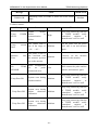
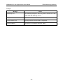
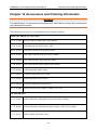
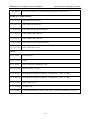
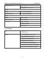
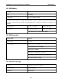
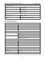
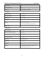
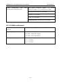
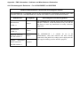
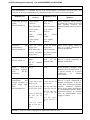
MENNMOVE 3 Vital Signs Monitor User Manual
Accessories and Ordering Information
Chapter 12 Accessories and Ordering Information
WARNING
The specification of accessories recommended is listed below. Using other accessories
may damage the monitor.
The following accessories are recommended when using this monitor.
MENNEN MEDICAL LTD. SpO2
12.01.110492
SH3 Neonate,resuable,SpO2 Warp Sensor,
12.01.110515
SH4 adult soft-tip SpO2 sensor, TPU
02.01.110531
SH4 adult silicone soft-tip SpO2 sensor
12.01.110521
SH5 SpO2 Silicone Soft-tip Sensor, pediatric
12.01.109069
SH1 adult reusable SpO2 Sensor(LEMO)
12.01.109079
SH1 adult reusable SpO2 finger sensor (DB9)
01.57.040196
Adult disposable SpO2 sensor
01.57.040197
Pediatric Disposable SpO2 sensor
01.57.040198
Infant Disposable SpO2 sensor
01.57.040199
Neonatal Disposable SpO2 Sensor
01.13.210001
SpO2 extension cable, DB9 to LEMO, TPU, 2m
NELLCOR SpO2
11.15.30043
Nellcor Reusable Adult SpO2 Sensor (DS-100A OxiMax)
11.15.40096
Nellcor Reusable Adult/Neonate SpO2 Sensor (OXI-A/N OxiMax)
11.13.30131
Nellcor SpO2 Extension Cable
- 88 -
MENNMOVE 3 Vital Signs Monitor User Manual
Accessories and Ordering Information
NIBP
01.57.40020
NIBP Cuff, Infant, 10cm-19cm, reusable,CM1201
01.57.40018
NIBP Cuff, Pediatric, 18cm-26cm, reusable,CM1202
01.57.40029
NIBP Cuff, Adult, 25cm-35cm, reusable,CM1203
01.57.40074
NIBP Cuff, Adult, 33cm-47cm, reusable,CM1204
11.57.40097
NIBP Cuff for Neonatal, for single patient use,5.4cm ~9.1 cm
11.57.40098
NIBP Cuff for Neonatal, for single patient use,6.9cm ~ 11.7cm
01.59.036118
NIBP Tube for Adult Pediatric, 3m, Grey
01.57.040212
NIBP Cuff, Infant, 10cm-19cm, reusable,CM1301
01.57.040211
NIBP Cuff, Pediatric, 18cm-26cm, reusable,CM1302
01.57.040205
NIBP Cuff,Adult, 25cm-35cm, reusable,CM1303
01.57.040210
NIBP Cuff,Adult,33cm-47cm, reusable,CM1304
01.57.471021
Connecting Tube for Neonatal Cuff, 3m
TEMP (For T2 Module)
02.04.110140
Oral /axillary probe
02.04.110139
Rectal probe
11.57.110159
Probe covers
TEMP (For TH Module)
01.13.036415
TH module communication wire
12.08.208058
Probe covers for TH module (200 pieces/ package)
- 89 -
MENNMOVE 3 Vital Signs Monitor User Manual
12.08.208059
Accessories and Ordering Information
Probe cover loader for TH module (with 40 pieces probe cover)
TEMP (For F3000 Module)
11.57.471312
Filac 3000 Oral Probe 4ft
11.57.471313
Filac 3000 Oral Probe 9ft
11.22.066159
Filac 3000 Oral Isolation Chamber
11.57.471314
Filac 3000 Rectal Probe 4ft
11.57.471315
Filac 3000 Rectal Probe 9ft
11.22.066160
Filac 3000 Rectal Isolation Chamber
11.57.471316
Filac 3000 Probe Covers
Others
01.57.78035
Printing Paper
03.28.101950
Trolley
01.13.36014
Power Cable(IEC Standard) ,1.8m
01.13.036106
Power cord(USA),1.8m
21.21.064167
Rechargeable Lithium-Ion Battery/ TWSLB-008 (14.8V, 4.4 Ah)
21.21.064168
Rechargeable Lithium-Ion Battery/ TWSLB-009 (14.8V, 2.2 Ah)
11.13.01950
Power cord(3C),3m
11.13.114214
Ground Cable
11.23.068003
USB barcode scanner (Cipher LAB 1000U, USB port, conntact, CCD scan)
- 90 -
MENNMOVE 3 Vital Signs Monitor User Manual
and Service
Warranty
Chapter 13 Warranty and Service
13.1 Warranty
MENNEN MEDICAL LTD. warrants that MENNEN MEDICAL LTD.’s products meet the
labeled specifications of the products and will be free from defects in materials and workmanship
that occur within warranty period.
The warranty is void in cases of:
a) damage caused by mishandling during shipping.
b) subsequent damage caused by improper use or maintenance.
c) damage caused by alteration or repair by anyone not authorized by MENNEN MEDICAL
LTD..
d) damage caused by accidents.
e) replacement or removal of serial number label and manufacture label.
If a product covered by this warranty is determined to be defective because of defective materials,
components, or workmanship, and the warranty claim is made within the warranty period,
MENNEN MEDICAL LTD. will, at its discretion, repair or replace the defective part(s) free of
charge. MENNEN MEDICAL LTD. will not provide a substitute product for use when the
defective product is being repaired.
13.2 Contact Information
If you have any question about maintenance, technical specifications or malfunctions of devices,
contact your local distributor.
Alternatively, you can send an email to MENNEN MEDICAL LTD. service department at:
support@MENNEN MEDICAL LTD..com.cn
- 91 -
MENNMOVE 3 Vital Signs Monitor User Manual
Specifications
Appendix Specifications
A1.1 Classification
Anti-electroshock type
Class℃equipment and internal powered equipment
Anti-electroshock degree
SpO2, NIBP: BF
TEMP: CF (T2 module)
BF (TH module, F3000 module)
Ingress protection
IPX1 (With T2 or F3000 TEMP module: IPX0)
Working system
Continuous operation equipment
Compliant with standards
IEC 60601-1:1988+A1+A2, ISO 9919, EN 12470-4,
EN12470-5:2003,
EN
60601-1:1990+A1+A2,
IEC/EN 60601-2-30, IEC/EN 60601-1-2:2005+A1,
ANSI/AAMI SP10, IPC610,ISO13485
A1.2 Specifications
A1.2.1 Size and Weight
Size
174 mm (L) × 235 mm (H) × 189 mm (D)
Weight
≤3.5 kg (not including battery)
A1.2.2 Environment
The monitor may not meet the performance specifications given here if stored or used outside the
specified temperature and humidity ranges.
When the monitor and related products have differing environmental specifications, the effective
range for the combined products is that range which is common to the specifications for all
products.
Temperature
Working
+5 °C ~ +40 °C
With TEMP: +10 °C ~ +40 °C
- 92 -
MENNMOVE 3 Vital Signs Monitor User Manual
Transport and storage
Specifications
-20 °C ~ +55 °C
With TH module: -20 °C ~ +50 °C
Humidity
Working
25% ~ 80% (non-condensing)
Transport and storage
25% ~ 93% (non-condensing)
Altitude
Working
860hPa ~ 1060hPa
Transport and storage
700hPa ~ 1060hPa
Power supply
Voltage: 100V–240V ~
Frequency: 50Hz/60Hz
FUSE T 1.6AL
A1.2.3 Display
Device
5.6-inch color TFT
Resolution: 640×480
Messages
1 Power Supply Indicator LED (Green)
1 Power On Indicator LED (Green)
1 Alarm Indicator LED (Red/Yellow)
1 Charge Indicator LED (Yellow)
1 Alarm Mute Indicator LED (Backlight)
1 NIBP Working Status Indicator LED (Backlight)
3 indicating modes correspond to Alarm Mode
- 93 -
MENNMOVE 3 Vital Signs Monitor User Manual
Specifications
A1.2.4 Battery
Quantity
1
Type
Li battery
Capacitance
2.2Ah; 4.4Ah(optional)
Working period (With a new fully charged battery, at 25℃, continuous SpO2 measuring, NIBP
automatic measuring mode with the operating interval of 15 minutes, automatic recording per 10
minutes)
Operating time
2.2Ah: ≥240 min
4.4Ah: ≥480 min
Charge time
2.2Ah: ≤180 min
4.4Ah: ≤360 min
(The monitor is on or in standby mode.)
A1.2.5 Recorder
Record width
48 mm
Paper speed
25 mm/s
Recording types
Parameter list recording
Trend graph review recording
Alarm list recording
Real-time 8s waveform recording
Recording of all the data of current patient ID
Real-time alarm recording
A1.2.6 Data Storage
Trend
72 hours, at 1 min resolution
NIBP trend list
30, 000 groups
Alarm list
800 groups
- 94 -
MENNMOVE 3 Vital Signs Monitor User Manual
Specifications
A1.2.7 NIBP (Optional)
Mode
Manual, Auto, Continuous
Measuring interval in AUTO mode
1/2/3/4/5/10/15/30/60/90/120/240/480 min
Measure time in continuous measure 5 minutes, interval is 5s
mode
Measuring type
Systolic Pressure, Diastolic Pressure, Mean Pressure,
Pulse Rate
Measuring range
ADU mode
SYS 40 mmHg ~ 270 mmHg
DIA 10 mmHg ~ 215 mmHg
MAP 20 mmHg ~ 235 mmHg
PED mode
SYS 40 mmHg ~ 200 mmHg
DIA 10 mmHg ~ 150 mmHg
MAP 20 mmHg ~ 165 mmHg
NEO mode
SYS 40 mmHg ~ 135 mmHg
DIA 10 mmHg ~ 100 mmHg
MAP 20 mmHg ~ 110 mmHg
Alarm type
SYS, DIA, MAP, PR
Cuff Pressure measuring range
0 mmHg ~ 300 mmHg
Pressure resolution
1 mmHg
Maximum mean error
±5 mmHg
Maximum standard deviation
8 mmHg
Maximum measuring time of single ADU/PED 120s
measurement
NEO
90s
Typical measuring period
30s ~ 45s (depend on HR/motion disturbance)
- 95 -
MENNMOVE 3 Vital Signs Monitor User Manual
Specifications
Overpressure protection
ADU
(297±3) mmHg
PED
(240±3) mmHg
NEO
(147±3) mmHg
PR
Measuring range
40 bpm ~ 240bpm
Accuracy
±3bpm or 3.5%, whichever is greater
A1.2.8 SpO2 (Optional)
MENNEN MEDICAL LTD. module
Measuring Range
0 ~ 100 %
Alarm Range
0 ~ 100 %
Resolution
1%
Data update period
1s
Accuracy
Adult /Pediatric
±2 % (70%~100% SpO2)
Undefined (0~69% SpO2)
Neonate
±3 % (70%~100% SpO2)
Undefined (0~69% SpO2)
Pulse Rate
Measuring Range
25 bpm ~ 300 bpm
Alarm Range
30 bpm ~ 300 bpm
Resolution
1 bpm
Accuracy
±2bpm
Sensor
Red light
660±3 nm
Infrared light
905±5 nm
Emitted light energy
<15 mW
- 96 -
MENNMOVE 3 Vital Signs Monitor User Manual
Specifications
Nellcor module (optional)
Measuring Range
1% ~ 100%
Alarm Range
0% ~ 100%
Resolution
1%
Data update period
1s
Sensor Type
Accuracy
DS-100A, OXI-A/N
± 3%(70% ~ 100% SpO2)
Accuracy
* When the sensor is used on neonates as recommended, the specified accuracy range
increases by ±1 compared with that used on adults.
Pulse Rate
Measuring Range
20bpm ~ 300bpm
Alarm Range
30bpm ~ 300bpm
Resolution
1bpm
Accuracy
± 3bpm (20bpm ~ 250bpm)
Sensor
Wave length: approximately 660 and 900nm
Emitted light energy: <15mW
A1.2.9 TEMP (Optional)
T2 Module:
Monitor mode: 25°C ~ 45°C
Measuring range
Predict mode: 35.5°C~42°C
Working temperature
10°C ~ 40°C
Sensor type
Oral /axillary /rectal
Alarm range
35.5°C ~ 42°C
Resolution
0.1°C
Accuracy
Monitor mode: ±0.1°C (25°C ~ 45°C) (not including
transducer)
Response time
< 60s
Update time
1s ~ 2s
- 97 -
MENNMOVE 3 Vital Signs Monitor User Manual
Specifications
Warm-up time
<10s
Time for predicting
<30s
Calibration
Self-test interval: ≤5 minutes
TH Module:
Measuring range
34°C ~ 42.2°C
Working temperature
10°C ~ 40°C
Alarm range
35.5°C ~ 42°C
Resolution
0.1°C
Accuracy
±0.2°C (35.5°C ~ 42°C)
±0.3°C (out of the range mentioned above)
Response time
1s
F3000 Module:
Measuring range
30°C~43°C
Prediction measurement range
35°C~43°C
Cold mode prediction measurement range 33°C~43°C
Working temperature
10°C ~ 40°C
Sensor type
Oral /axillary /rectal
Alarm range
33°C ~ 43°C
Resolution
0.1°C
Accuracy
Monitoring Mode and Preditive Mode: ±0.1°C
Quick Predictive Mode: ±0.3°C
- 98 -
MENNMOVE 3 Vital Signs Monitor User Manual
Typical measurement
time
insertion into measurement site)
Specifications
(after Oral (Quick Predictive Mode): 3~5 seconds
(non-fever temps); 8~10 seconds (fever temps)
Oral (Predictive Mode): 6~10 seconds
Axillary: 8~12 seconds
Rectal: 10~14 seconds
Monitoring Mode (all sites): 60~120 seconds
A1.2.10 Wirless Network
Compliant
Directive
with
Standard
Frequency Range
and IEEE802.11b/g, R&TTE Directive (99/5/EEC)
2.412 GHz ~2.462 GHz (America)
2.412 GHz ~2.484 GHz (Japan)
2.412 GHz ~2.472 GHz (ETSI)
Working frequency segment
Ch1 ~ 11 (America)
Ch1 ~ 14 (Japan)
Ch1 ~ 13 (ETSI)
- 99 -
Appendix
EMC Information - Guidance and Manufacture’s Declaration
A2.1 Electromagnetic Emissions - For all EQUIPMENT and SYSTEMS
Guidance and manufacture’s declaration-electromagnetic emission
The MENNMOVE 3 is intended for use in the electromagnetic environment specified below, The
customer or the user of the MENNMOVE 3 should assure that it is used in such and environment.
Emission test
RF emissions
CISPR 11
RF emissions
CISPR 11
Harmonic emissions
IEC/EN 61000-3-2
Compliance
Group 1
Electromagnetic environment-guidance
The MENNMOVE 3 uses RF energy only for its internal
function. Therefore, its RF emissions are very low and are
not likely to cause any interference in nearby electronic
equipment.
Class A
Class A
Voltage
fluctuations
/flicker emissions
Complies
IEC/EN 61000-3-3
The MENNMOVE 3 is suitable for use in all
establishments, other than domestic and those directly
connected to the public low-voltage power supply network
that supplies building used for domestic purposes.
A2.2 Electromagnetic Immunity - For all EQUIPMENT and SYSTEMS
Guidance and manufacture’s declaration – electromagnetic immunity
The MENNMOVE 3 is intended for use in the electromagnetic environment specified below. The
customer or the user of MENNMOVE 3 should assure that it is used in such an environment.
Immunity test
IEC/EN 60601
test level
Electrostatic discharge ±6 kV contact
(ESD)
±8 kV air;
IEC/EN 61000-4-2
With TH module:
Compliance level
±6 kV contact
±8 kV air
With TH module:
±2 kV contact
±2 kV contact
±4kV air.
±4kV air.
With
module:
F3000 With
module:
Electromagnetic environment
-guidance
Floors should be wood, concrete
or ceramic tile. If floor are covered
with synthetic material, the
relative humidity should be at least
30%.
F3000
±4 kV contact
±4 kV contact
±6kV air.
±6kV air.
Electrical
transient/burst
fast ±2kV for power ±2 kV for power Mains power quality should be
supply lines;
supply lines;
that of a typical commercial or
hospital environment.
IEC/EN 61000-4-4
With TH module:
With TH module:
±0.5 kV for power ±0.5 kV for power
supply lines.
supply lines.
Surge
IEC/EN 61000-4-5
±1 kV differential ±1 kV differential Mains power quality should be
mode
mode
±2
kV that of a typical commercial or
common mode
hospital environment.
±2 kV common
mode
Power
frequency 3A/m
(50/60Hz) magnetic
field
IEC/EN
61000-4-8
3A/m
Power frequency magnetic fields
should be at levels characteristic of
a typical location in a typical
commercial
or
hospital
environment.
Voltage dips, short
interruptions
and
voltage variations on
power supply input
lines
<5% UT
Mains power quality should be
that of a typical commercial or
hospital environment. If the user
of the EUS TUltrasound Scanner
requires
continued
operation
during power mains interruptions,
it is recommended that the EUS T
Ultrasound Scanner be powered
from an uninterruptible power
supply or a battery.
IEC/EN61000-4-11
<5% UT
(>95% dip in UT) (>95% dip in UT)
for 0.5 cycle
for 0.5 cycle
40% UT (60% dip 40% UT (60% dip
in UT) for 5 cycles in UT) for 5 cycles
70% UT (30% dip
in UT) for 25
70% UT (30% dip cycles
in UT) for 25
<5% UT (>95%
cycles
dip in UT) for 5
sec
<5% UT (>95%
dip in UT) for 5
sec
NOTE UT is the a.c. mains voltage prior to application of the test level.
A2.3 Electromagnetic Immunity - For EQUIPMENT and SYSTEMS that are not LIFE-SUPPORTING
Guidance and manufacturer’s declaration – electromagnetic immunity
The MENNMOVE 3 is intended for use in the electromagnetic environment specified below. The
customer or the user of MENNMOVE 3 should assure that it is used in such an environment.
Immunity
test
Conducted
RF IEC/EN
61000-4-6
Radiated RF
IEC/EN
61000-4-3
IEC/EN 60601 test
level
3 Vrms
Compliance
level
3Vrms
150 kHz to 80 MHz
3 V/m
80 MHz to 2.5 GHz
3 V/m
Electromagnetic environment -guidance
Portable and mobile RF communications
equipment should be used no closer to any
part of the EUS T Ultrasound Scanner,
including cables, than the recommended
separation distance calculated from the
equation applicable to the frequency of the
transmitter.
Recommended separation distance
 3.5 
d =  P
 V1 
 3.5 
d =   P 80 MHz to 800 MHz
 E1 
7
d =   P 800 MHz to 2.5 GHz
 E1 
Where P is the maximum output power rating
of the transmitter in watts (W) according to
the transmitter manufacturer and d is the
recommended separation distance in metres
(m).
Field strengths from fixed RF transmitters, as
determined by an electromagnetic site
survey,a should be less than the compliance
level in each frequency range.b
Interference may occur in the vicinity of
equipment marked with the following
symbol:
NOTE 1 At 80 MHz and 800 MHz, the higher frequency range applies.
NOTE 2 These guidelines may not apply in all situations. Electromagnetic propagation is affected by
absorption and reflection from structures, objects and people.
a
Field strengths from fixed transmitters, such as base stations for radio (cellular/cordless)
telephones and land mobile radios, amateur radio, AM and FM radio broadcast and TV broadcast
cannot be predicted theoretically with accuracy. To assess the electromagnetic environment due to
fixed RF transmitters, an electromagnetic site survey should be considered. If the measured field
strength in the location in which the EUS TUltrasound Scanner is used exceeds the applicable RF
compliance level above, the EUS T Ultrasound Scanner should be observed to verify normal operation.
If abnormal performance is observed, additional measures may be necessary, such as reorienting or
relocating the EUS TUltrasound Scanner.
b
Over the frequency range 150 kHz to 80 MHz, field strengths should be less than 3 V/m.
A2.4 Recommended Separation Distances
Recommended separation distances between portable and mobile RF communications
equipment and the MENNMOVE 3 Vital Signs Monitor
The MENNMOVE 3 is intended for use in an electromagnetic environment in which radiated RF
disturbances are controlled. The customer or the user of the MENNMOVE 3 can help prevent
electromagnetic interference by maintaining a minimum distance between portable and mobile RF
communications equipment (transmitters) and the MENNMOVE 3 as recommended below, according
to the maximum output power of the communications equipment.
Separation distance according to frequency of transmitter (m)
Rated maximum
output power of
transmitter (W)
150 kHz to 80 MHz
80 MHz to 800 MHz
800 MHz to 2.5 GHz
 3.5 
d =  P
 V1 
 3.5 
d =  P
 E1 
7
d =  P
 E1 
0.01
0.12
0.12
0.23
0.1
0.37
0.37
0.73
1
1.2
1.2
2.3
10
3.7
3.7
7.3
100
12
12
23
For transmitters rated at a maximum output power not listed above, the recommended separation
distance d in meters (m) can be estimated using the equation applicable to the frequency of the
transmitter, where P is the maximum output power rating of the transmitter in watts (W) according to
the transmitter manufacturer.
NOTE 1: At 80 MHz and 800 MHz, the separation distance for the higher frequency range applies.
NOTE 2: These guidelines may not apply in all situations. Electromagnetic propagation is affected by
absorption and reflection from structures, objects and people.