1
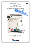
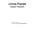
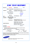
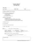
R
PowderMidcap™ 811 - 821
Powdercap™ 811 - 821
02/2004
User’s Manual
1
R
So m m a r y
1
Introduction
page 5
2
Front control panel description
page 7
3
C alibration of the “F a n F a il u r e ” indicator
page 10
4
Replacement of the filter
page 12
5
Replacement of the prefilter
page 13
6
Exploded views of the Powdercap™ et powdermidcap™
page 14
7
The technical cases
page 17
8
Electrical diagrams
page 19
9
Spécifications of the Powdercap™ et powdermidcap™
page 21
3
I n tr o d ucti o n
1
W h a t m ust b e a b so l u t e ly k n o w n b e fo r e usi n g y o u r P o w d e rc a p™ ?
O r h o w to m a n i p u l a t e i n tot a l s a f e ty?
C ongratulations for your excellent choice, your new equipment is manufactured
according to a very high standard of quality which will guarantee its safe use over the
years to come.
The Powdercap™ combines operator protection and protection of the environment by
using a unique air recirculation system directly into the laboratory.This is being made
possible by the use of highly specialized filters which trap toxic molecules. This process
named chemical adsorption allows to obtain purified air at the filter exhaust that is free
from chemical pollutants. The efficiency and filter lifetime directly depend on the
nature of the manipulation that will be carried out in the enclosure.
I m p o rt a n t n otic e fo r y o u r s a f e ty
The Powdercap™ is designed to protect the user while weighing powders or powders
diluted into water. In any case, the Powdercap™cannot be used for weighing powders
in a boiling liquid or heated in the enclosure. The filtration system can be seriously
damaged if used in inappropriate conditions and may not provide full protection to the
user.
A careful reading of this user's manual will insure you a worry free experience while
working in total safety.
5
R
2
F r o n t co n tr o l p a n e l d e scr i p ti o n
P o w d e r m i d c a p™ 8 1 1 - 8 2 1
SE 1 0
l
f
R
P o w d e r m i d c a p™ 8 2 1
M a d e i n F r a nc e
N U M BER
N U M ER O
N U M M ER
AC
230
V
132
2003
50
Hz
47
W
R
PARC D’AFFAIRES DES P O RTES
BP 403 - 27104 VAL DE REUIL C edex (FRAN CE)
TÉL : 02 32 09 55 80 - FAX : 02 32 09 55 90
m
Ri g h t h a n d si d e of t h e fr o n t p a n e l co n tr o l .
f
l
m
- Ventilator/fan on-off switch
- Type label.
- N ame of the manufacturer or its distributor
k
M i d d l e p a rt of t h e fr o n t co n tr o l p a n e l .
R
Le ft si d e of t h e fr o n t co n tr o l p a n e l I .
7
R
2
F r o n t co n tr o l p a n e l d e scr i p ti o n
P o w d e rc a p™ 8 1 1 - 8 2 1
l
f
R
P o w d e rc a p™8 1 1
M a d e i n F r a nc e
N U M BER
N U M ER O
N U M M ER
AC
230
V
150
2003
50
Hz
47
SE 1 0
g
W
R
PARC D ’AFFAIRES DES P O RTES
BP 4 0 3 - 2 7 1 0 4 VAL DE REUIL C edex (FRA N CE)
TÉL : 0 2 3 2 0 9 5 5 8 0 - FAX : 0 2 3 2 0 9 5 5 9 0
m
j
Ri g h t h a n d si d e of t h e fr o n t p a n e l co n tr o l .
f
l
m
- Ventilator/fan on-off switch
- Type label.
- N ame of the manufacturer
O r its distributor
g
- (Red) warning light “F a n F a il u r e ”
J
.
- External potentiometer
for the “F a n F a il u r e ” setting
k
M i d d l e p a rt of t h e fr o n t co n tr o l p a n e l.
R
Le ft si d e of t h e fr o n t co n tr o l p a n e l I .
8
R
2
1 - I d e n tific a ti o n t a g (right side of the front panel)
R
P o w d e rc a p™8 1 1
M a d e i n F r a nc e
N U M BER
N U M ER O
N U M M ER
150
AC 230
V
c
a)
b)
c)
d)
e)
50
SE 1 0
10/2000
Make sure that your power supply complies with the actual supply voltage
a
of your Powdercap™.
b
2003
Hz
47
d
W
e
Powdercap™ model
Serial number
Actual supply voltage
H e rt z frequency
Total power in W a tt
2 - N a m e of t h e m a n u f a ct u r e r o r its d istr i b u to r
(right side of the front panel)
Label with the manufacturer or distributor contact detail label.
O NE ELM S Q UARE 1980 TURNPIKE STREET
N O RTH AN D O VER - MA 01845P
PH O NE (978) 975-336 FAX ((978) 975-2730
3 - Sw itc h i n g o n t h e e q u i p m e n t
Your Powdercap™ is equipped with 1 on-off switche
- An on-off switch with a green light for the
control of the fan.
Before using your Powdercap™, the fan switch must be turned on “ I
“Fan Failure” light will illuminate but should go out after a few seconds.
“. The red
If the light and the warning alarm do not stop, go to section 3.
9
R
3
C a li b r a ti o n of t h e
“ F A N F A IL URE ” i n d ic a to r
P o w d e rc a p™ 8 1 1 - 8 2 1
The “F a n F a il u r e ” alarm warns the user of any fan malfunction. Prior to use, it is
necessary to calibrate this alarm according to the following procedure:
Ext e r n a l c a li b r a ti o n p r oc e d u r e
To be done when using your Powdercap™ for the first time
This calibration has to be done when the fans are running, with the filters installed and
only if the “fan failure” red warning light g (located on the right side of front control
panel I) and alarm are active.
* G ently turn with a screwdriver the potentiometer screw J located under the red
warning light g towards the left or the right until the visual and audible alarm stops. If
you cannot calibrate the visual and audible alarm with the potentiometer J, then
follow the instructions hereunder.
I n t e r n a l c a li b r a ti o n p r oc e d u r e
(To be done by qualified maintenance technicians)
1 Remove the entire acrylic front panel V F (Lower door + Visor). Unlock the fasteners
W which maintain the panel I. Lower the panel I.
2 With the screwdriver (provided with the unit in the technical casing), gently turn the
grey potentiometer S clockwise or counter clockwise until neither of the yellow light
T1or yellow light T2 remain on. Within this range, the audible alarm stops.
3 Fan failure detection: Put on a thick glove and decrease the fan rotor rotation speed
by pushing on it with the palm of your hand. O ne of the 2 warning lights T1 or T2
should go on. Remove your hand. O nce the fan rotor is back to normal speed, the
visual and audible alarm will stop.
4 Raise the panel I and lock the fasterns W. Replace the acrylic front panel V F.
10
R
3
P o w d e rc a p™ 8 1 1 - 8 2 1
H
H
VF
M1
I
I
W
W
X
U
M1
g
I
T1
0
WSE 117 07/2002
j
M1
: Circuit board installed in filter housing H .
S
: G rey multi turn potentiometer for the calibration of the “Fan Failure”
indicator.
S
T2
T1 -T2 : Yellow warning lights located on electronic board M 1 , determines the
external calibration area.
U
: Circuit board M 1 protection fuse
11
R
4
Re m p l a c e m e n t d u filtr e
M
K
L
H
To r e p l a c e a filt e r, y o u m a y sto p y o u r P o w d e rc a p™,P o w d e r m i d c a p™.
1
Remove all 16 white plastic caps M covers located on top the filter housing H .
2
Unscrew all screws with the box spanner provided with your Powdercap™ and
remove the top panel K .
3
With the help of two metal “L” shaped bars provided and remove the
particulate filter L.
4
Take the new filter and place it in the filter housing H but make sure to
position in the direction of the filtration flow (see directions on the
information sticker found on the filter shell).
5
Place the top panel back K to its original position on the Powdercap™ filter
housing H and tighten it in place with the 16 screws which were previously
removed.
6
You can cover all screws with the white plastics caps M .
Your Powdercap™ is now ready for use.
12
R
5
Re m p l a c e r l e p r é filtr e
H
VF
H
J
M1
I
I
W
W
X
U
To r e p l a c e t h e p r e filt e r
1
Turn off your product.
2
Use gloves to protect your hands.
3
Remove the entire acrylic front panel V F (Lower door + Visor).
4
Unlock the fasteners W which maintain the panel I. Lower the panel I.
5
Remove the saturated prefilter J and replace it with an new prefilter.
O ne your prefilter is properky in place, raise the panel I and lock the
fasterns W.
6
Replace the acrylic front panel.
Your Powdercap™ or Powdermidcap™ is ready.
13
Ex p l o d e d v i e w
6
P o w d e r m i d c a p™ 8 1 1 - 8 2 1
+
,
3
(
*
)
#
"
&
1
#
6
5
'
!
R
14
Ex p l o d e d v i e w
6
P o w d e rc a p™ 8 1 1 - 8 2 1
+
,
3
(
*
)
#1
"
&
1
#2
6
5
'
!
R
:
15
6
SP ARE PARTS
REFEREN CE
DESI G NATI O N
Z
Air velocity meter
A:
Spill tray
B
Back panel
C 1:
Side panel B
C 2:
Side panel P
F:
Visor
V:
Lower door for Powdercap™ or
Powdermidcap™
Q :
G :
Two plastic hingers
Side clamp
b : O PTN 5SF
O PTN 5S G B
O PTN 5SUS
Lighting option Europe 230V
Lighting option UK 230V
Lighting option USA 127V
R
Electrical
Electrical
Electrical
Electrical
S : PIDB O 086
U : PIDMSU824
PIDMS032
Six vis nylon screwsM8x25
Two screws PP M6x16
Six nuts PP black M6
L:
Filter HEPA H14 753 X 403 X 62 mm
H
K
J
I
Filter housing
Top panel
cordset
cordset
cordset
cordset
(Europe)
(USA - Ja pon)
(UK)
(Suisse)
Prefilter for Powdercap™ ou Powdermidcap™
Panel
16
El e ctr ic a l (Te c h n ic a l) p a rts
7
P o w d e r m i d c a p™ 8 1 1 - 8 2 1
< =
>
?
@
d
<
1
2
3
4
5
A
Electrical socket
Fuses 5 X 20 4A
Fuse holder
Electrical plug
Ventilator
G eneral switch
R
17
El e ctr ic a l (Te c h n ic a l) p a rts
7
P o w d e rc a p™ 8 1 1 - 8 2 1
< =
>
?
" #
@
A
<
1
2
3
4
5
Electrical socket
Fuses 5 X 20 4A
Fuse holder
Electrical plug
Ventilator
6
A
“F a n F a il u r e ” circuit board
G eneral switch
B
C
“F a n F a il u r e ”warning light
“F a n F a il u r e ” potentiometer
R
18
8
El e ctr ic a l w i r i n g d i a g r a m
P o w d e r m i d c a p™ 8 1 1 - 8 2 1
C
ELECTRIC AL
C O N N EXI O N
V e n til a to r
D
F A N SW ITC H
W IT H
W AR N I N G LI G H T
R
19
8
El e ctr ic a l w i r i n g d i a g r a m
P o w d e rc a p™ 8 1 1 - 8 2 1
C
ELECTRIC AL
C O N N EXI O N
L
E
N
4A
V e n til a to r
D
J1
Fuse
50 m A
1
1
2
2
FA N
F A IL URE
CIRC U IT
B O ARD
3
4
1
1
2
2
B A
J2
3
1
2
J3
3
1
2
3
J4
1 2 3
4
6
5
6
J5
5
1 2 3
h
i
efg
E
ON
2
1
2a
1a
OFF
“ F A N F A IL URE ”
F A N SW ITC H
P O TE N TI O M ETER
FOR
& W AR N I N G LI G H T W EI G H TI N G
F A N SW ITC H
W IT H
W AR N I N G LI G H T
R
20
9
S p e c ifi c a tio n s
Model
P o w d e r m i d c a p™
P o w d e r m i d c a p™
811
821
P o w d e rc a p™ P o w d e rc a p™
811
811
799
721
555
742
496
480
799
969
622
742
749
580
799
721
555
742
496
480
799
969
622
742
749
580
1
1
1
1
1
1
1
1
“ F a n f a il u r e ” alarm
-
-
Serial
Serial
Switch for weighting
-
-
Serial
Serial
O ption 5S
O ption 5S
O ption 5S
O ption 5S
External dimensions m m
Length
Height
Depth
Length
Internal dimensions m m
Height
Depth
Q uantity of fans
Q uantity of HEPA filters (H 1 4)
753X403X62 mm
Lighting
1x11W
Volume of air treated
m3/ h
170
170
170
170
F a c e velo city
m /s
0,55
0,55
0,55
0,55
Internal volume of enclosure
m3
0,15
0,32
0,32
0,32
Ti m e / h o u r
18,9
9,9
18,9
9,9
Air exchange per hour
Sound level
dBA
54
54
54
54
Power consumption
W a tt
47
47
47
47
Ele ctric a l volt a g e
V o lt
230
230
230
230
Hz
50
50
50
50
A
0,31
0,31
0,31
0,31
Frequency
Amperage absorbed
R
21
9
S p e c ifi c a tio n s
Model
External dimensions i nc h e s
Length
Height
Depth
Length
Internal dimensions i nc h e s
Height
Depth
Q uantity of fans
P o w d e r m i d c a p™
P o w d e r m i d c a p™
811
821
31 1/2
28 1/3
21 6/7
29
19
18 7/8
31
38 1/5
24 1/2
29
29 1/2
22 4/5
P o w d e rc a p™ P o w d e rc a p™
811
31 1/2
28 1/3
21 6/7
29
19
18 7/8
811
31
38 1/5
24
29
29 1/2
22 4/5
1
1
1
1
1
1
1
1
“ F a n f a il u r e ” alarm
-
-
Serial
Serial
Switch for weighting
-
-
Serial
Serial
O ption 5S
O ption 5S
O ption 5S
O ption 5S
Q uantity of HEPA filters (H 1 4)
753X403X62 mm
Lighting
1x13W
Volume of air treated
cf m
105
105
105
105
F a c e velo city
fp m
118
118
118
118
Internal volume of enclosure
cf
5,3
11,3
5,3
11,3
20
10,4
20
10,4
Air exchange per minute
Ti m e / m n
Sound level
dBA
56
56
56
56
Power consumption
W a tt
50
50
50
50
Ele ctric a l volt a g e
V o lt
115
115
115
115
Hz
60
60
60
60
A
0,62
0,62
0,62
0,62
Frequency
Amperage absorbed
R
22
P o w d e r M i d c a p™ 8 1 1
&
P o w d e rc a p™ 8 1 1
799 m m
31 1/2”
9
490 m m
I
R
350 m m
9 5/7”
13 3/4”
721 m m
28 1/3”
246 m m
O
742 m m
785 m m
29 1/4”
31”
555 m m
21 6/7”
R
23
P o w d e r M i d c a p™ 8 2 1
&
P o w d e rc a p™ 8 2 1
799 m m
31 1/2”
9
490 m m
I
R
350 m m
9 5/7”
13 3/4”
969 m m
38 1/5”
O
785 m m
29 1/4”
31”
246 m m
742 m m
622 m m
24 1/2”
R
24
w w w. e r l a b - d fs.c o m
W o r l d Le a d e r
i n m o l e cu l a r filtr a ti o n t e c h n o l o g y si nc e 1 9 6 8
E UR O PE
FRA N CE :
G ERM A N Y :
SP A I N :
IT ALY :
UK :
e r l a b D. F. S. S.A.S.
Parc d’affaires des Portes
BP 403
27104 Val de Reuil C edex
Tél :
Fax :
+ 33 (0)2 32 09 55 80
+ 33 (0)2 32 09 55 90
e r l a b D. F. S. S.A.S.
erla b Vertretungsbüro Deutschland
G ustav-Heinemann-Ufer 54
50 968 K Ö LN
Tel :
Fax :
e r l a b S.L..
O ficina C omercial en España
Ruiz Alarcón, 7 - 1°
28014 Madrid
Tel :
Fax :
e r l a b D. F. S. S.A.S.
Ufficio di rappresentanza in Italia
Via Cusani, 5
20121 Milano
Tel :
Fax :
e r l a b D. F. S. S.A.S.
UK and IRELAN D representationoffice
St Thomas’s House / St Thomas’s square
Salisbury - SPI IBA Wiltshire
P h o n e : 01722 341 940
Fax :
01722 341 950
E- M a il : Ventes @ erlab.net
0211 / 39 50 41
0211 / 39 8 22 15
E- M a il : Verkauf @ erlab.net
91 701 02 53
91 701 02 77
E- M a il : Ventas @ erlab.net
02 89 00 771
02 72 097 812
E- M a il : Vendite @ erlab.net
E- M a il : SalesUK @ erlab.net
N O RT H A M ERIC A
USA :
ASI A
M ALA YSI A :
CHIN A :
e r l a b ® i nc.
O ne Elm Square
1980 Turnpike Street
North Andover, MA 01845
e r l a b ® Asia Sdn Bhd
25 jalan Firma
2 / 1Kawasan Perindustrian - Terbrau
81 100 Johor Bahru State
Malaysia
®
e r l a b D. F. S. Ltd
139, Chang Jiang Rd. ( C )
Kunshan development Zone
Kunshan, Jinagsu Province
P.R. China 215300
P h o n e : (800) 964 - 4434
Fax :
1 (978) 975 - 2730
E- M a il : C aptairSales @ erlab.com
Tél :
Fax :
+ 60 (0) 7 3 555 724
+ 60 (0) 7 3 552 810
E- M a il : erlab @ tm.net.my
Tél :
Fax :
86 512 573 13 701
86 512 573 13 702
E- M a il : sales.china @ erlab.net