1
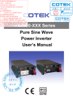
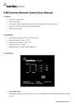
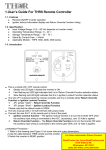
1.User’s Guide For CR6 Remote Controller 1-1. Features z z z z z 1-2. z z z z z Battery bank voltage display Output power display Error condition indicator(High Battery, Low Battery, Over Temperature, Over Load conditions) Action condition indicator(INV, GRID, POWER SAVING) Failed connection display Specification Input Voltage : 10.5 – 30Vdc Operating Temperature Range : 0 – 40 ℃ Storage Temperature Range : - 30 ℃ - 70 ℃ Stand-By Current Draw : < 80mA Applicable Models : SK700 / 1000 / 1500 / 2000 / 3000 / ST Series (except ST600) 1-3. Introduction z z z z z z z z z z Power ON/OFF Switch: Power ON/OFF switch is to turn the inverter on or off. You are supposed to hear one beep sound every time you switch on or off. Battery voltage indicator: This bar chart controls a light that will move up and down as the battery voltage changes. Ideally, the voltage should remain in the green Ares of the bar chart. If the voltage goes into the red area at the top and bottom of the graph, inverter may shut down. Output power indicator: The AC load watt chart indicates the power drawn from the power inverter by the load. Ideally, the watt indicator should remain in the green & orange area of the bar chart. If the OUTPUT POWER indicator is up to the red area of the bar, the light will flash and the inverter will shut down for inverter safety. Over voltage indicator: The over voltage indicator is to indicate that the power inverter shuts down because its input voltage is above 12 / 24 VDC. Under voltage indicator: The under voltage indicator is to indicate that the power inverter shuts down because its input voltage is below 12 / 24 VDC. Over temp indicator: The over temp indicator is to indicate that the power inverter shuts down because of overheating. The over temp indicator will be OFF when the power inverter cools down. Overload indicator: The overload indicator is to indicate that the power inverter shuts down because of short circuit or overload problems. INV. indicator: The inv. indicator is to indicate that the inverter is ready. GRID indicator: The GRID indicator is to indicate that you are using AC supply. PWR.SAV. Indicator:Power saving functions are described below: LED Solid Flashing Off Meaning Ready Active Inactive Inverter Output ON OFF The wire JP1 is placed inside the remote controller and it is to present either Return Override Function or Ignition lockout function. * JP1 jumper “Short” - Return Override Function * JP1 jumper “Open” – Ignition Lockout Function Please note that the default mode is Short. The connector connected to AUX wire must go with 12V / 0.5A fuse by proper sizes. Connect the wire RJ-11 to the remote port in front of the panel. * Ignition Lockout function – The ignition lockout function is to turn the Inverter OFF when the auxiliary input wiring is connected to the ACC, and 12 Volts is applied. * Return Override Function – The Return Override Function is to turn the inverter ON when the auxiliary input wiring is connected to the reverse gear Shift, and 12 Volts is applied. Installation Procedure: 1. Refer to the drawing (see Figure 2) for hole and cutout dimensions. 2. Use the cable between CR6 remote and the inverter. 3. Switch the inverter to REMO position. PHONE JACK JP1 (on the PCB) AUX Figure 2 1-4. Drawings of CR6 Remote Control Cables C O N D U C T O R I N S U L A T I O N J A C K E T C A B L E S T R U C T U R E (A-A) WARNING! DO NOT use standard telephone cable.