1
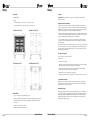
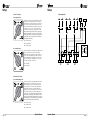
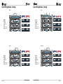
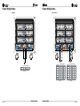
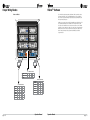
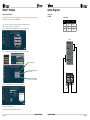
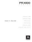
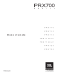
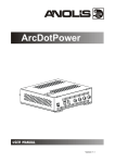
Operation Manual
Obtaining Other Language Versions: To obtain information in another language about the use of this product, please contact your local Crown Distributor. If you need
assistance locating your local distributor, please contact Crown at 574-294-8000.
This manual does not include all of the details of design, production, or variations of the equipment; nor does it cover every possible situation which may arise during
installation, operation or maintenance.
The information provided in this manual was deemed accurate as of the publication date; however, updates to this information may have occurred. To obtain the latest
version of this manual, please visit the Crown website at www.crownaudio.com.
Trademark Notice: Crown, Crown Audio, IQ, BCA, and Amcron are registered trademarks of Crown International. HiQnet is a trademark of
Harman International Industries, Inc. Other trademarks are the property of their respective owners.
Some models may be exported under the name Amcron®.
©2011 by Harman International. 1718 W. Mishawaka Rd., Elkhart, Indiana 46517-9439 U.S.A. Telephone: 574-294-8000.
142483-1 - 5/11
Important Safety Instructions
DECLARATION OF CONFORMITY
1. Read these instructions.
WATCH FOR THESE SYMBOLS:
2. Keep these instructions.
The lightning bolt triangle is used to alert the user to the risk of electric
shock.
3. Heed all warnings.
4. Follow all instructions.
The exclamation point triangle is used to alert the user to important
operating or maintenance instructions.
5. Do not use this apparatus near water.
6. Clean only with a dry cloth.
7. Do not block any ventilation openings. Install in accordance with the
manufacturer’s instructions.
8. Do not install near any heat sources such as radiators, heat registers,
stoves, or other apparatus (including amplifiers) that produce heat.
9. Do not defeat the safety purpose of the polarized or grounding-type
plug. A polarized plug has two blades with one wider than the other.
A grounding-type plug has two blades and a third grounding prong.
The wide blade or the third prong is provided for your safety. If the
provided plug does not fit into your outlet, consult an electrician for
replacement of the obsolete outlet.
10. Protect the power cord from being walked on or pinched, particularly
at plugs, convenience receptacles, and the point where they exit from
the apparatus.
11. Only use attachments/accessories specified by the manufacturer.
12. Use only with a cart, stand, tripod, bracket, or table specified by the
manufacturer, or sold with the apparatus. When a cart is used, use
caution when moving the cart/apparatus combination to avoid injury
from tip-over.
13. Unplug this apparatus during lightning storms or when unused for
long periods of time.
14. Refer all servicing to qualified service personnel. Servicing is required
when the apparatus has been damaged in any way, such as powersupply cord or plug is damaged, liquid has been spilled or objects
have fallen into the apparatus, the apparatus has been exposed to rain
or moisture, does not operate normally, or has been dropped.
15. Use the mains plug to disconnect the apparatus from the mains.
16. WARNING: TO REDUCE THE RISK OF FIRE OR ELECTRIC SHOCK, DO
NOT EXPOSE THIS APPARATUS TO RAIN OR MOISTURE.
17. DO NOT EXPOSE THIS EQUIPMENT TO DRIPPING OR SPLASHING
AND ENSURE THAT NO OBJECTS FILLED WITH LIQUIDS, SUCH AS
VASES, ARE PLACED ON THE EQUIPMENT.
18. THE MAINS PLUG OF THE POWER SUPPLY CORD SHALL REMAIN
READILY OPERABLE.
T O PREVENT ELECTRIC SHOCK, DO NOT REMOVE TOP OR BOTTOM
COVERS. NO USER SERVICEABLE PARTS INSIDE. REFER SERVICING TO
QUALIFIED SERVICE PERSONNEL.
T O COMPLETELY DISCONNECT THIS EQUIPMENT FROM THE
AC MAINS, DISCONNECT THE POWER SUPPLY CORD PLUG FROM THE
AC RECEPTACLE. THE MAINS PLUG OF THE POWER SUPPLY CORD
SHALL REMAIN READILY OPERABLE.
IMPORTANT
VRacks require Class 2 output wiring.
Issued By: H
arman International.
1718 W. Mishawaka Rd.
Elkhart, IN 46517 U.S.A.
FOR FIELD SERVICE
QUESTIONS CALL:
1 800 342 6939
European Representative’s Name and Address:
David J. Budge
10 Harvest Close
Yateley, GU46 6YS
United Kingdom
Equipment Type: Commercial Audio Power Amplifiers
Family Name: ITECH-HD
Model Names: VRack
EMC Standards:
MAGNETIC FIELD
EN 55103-1:1997 Electromagnetic Compatibility - Product Family Standard for Audio, Video, Audiovisual and Entertainment Lighting Control Apparatus for
Professional Use, Part 1: Emissions
EN 55103-1:1997 Magnetic Field Emissions-Annex A @ 10 cm and 20 cm
CAUTION! Do not locate sensitive high-gain equipment such as
preamplifiers or tape decks directly above or below the unit. Because this
amplifier has a high power density, it has a strong magnetic field which can
induce hum into unshielded devices that are located nearby. The field is
strongest just above and below the unit.
EN 61000-3-2:2005 & Amd 1: 2008 Limits for Harmonic Current Emissions (equipment input current ≤16A per phase)
If an equipment rack is used, we recommend locating the amplifier(s) in
the bottom of the rack and the preamplifier or other sensitive equipment at
the top.
EN 61000-4-2:2001 Electrostatic Discharge Immunity (Environment E2-Criteria B, 4k V Contact, 8k V Air Discharge)
EN 61000-3-3:1998 Limitation of Voltage Fluctuations and Flicker in Low-Voltage Supply Systems Rated Current ≤16A
EN 55022:2006 Limits and Methods of Measurement of Radio Disturbance Characteristics of ITE: Radiated, Class B Limits; Conducted, Class A
EN 55103-2:1997 Electromagnetic Compatibility - Product Family Standard for Audio, Video, Audiovisual and Entertainment Lighting Control Apparatus for
Professional Use, Part 2: Immunity
EN 61000-4-3:2006 Radiated, Radio-Frequency, Electromagnetic Immunity (Environment E2, Criteria A)
EN 61000-4-4:2007 Electrical Fast Transient/Burst Immunity (Criteria B)
EN 61000-4-5:2006 Surge Immunity (Criteria B)
FCC COMPLIANCE NOTICE
This device complies with part 15 of the FCC rules. Operation is subject
to the following two conditions: (1) This device may not cause harmful
interference, and (2) this device must accept any interference received,
including interference that may cause undesired operation.
CAUTION: Changes or modifications not expressly approved by the
party responsible for compliance could void the user’s authority to
operate the equipment.
NOTE: This equipment has been tested and found to comply with
the limits for a Class B digital device, pursuant to part 15 of the FCC
Rules. These limits are designed to provide reasonable protection
against harmful interference in a residential installation. This equipment
generates, uses, and can radiate radio frequency energy and, if not
installed and used in accordance with the instruction manual, may
cause harmful interference to radio communications. However, there is
no guarantee that interference will not occur in a particular installation.
If this equipment does cause harmful interference to radio or television
reception, which can be determined by turning the equipment off and
on, the user is encouraged to try to correct the interference by one or
more of the following measures:
EN 61000-4-6:2006 Immunity to Conducted Disturbances Induced by Radio-Frequency Fields (Criteria A)
EN 61000-4-11:2004 Voltage Dips, Short Interruptions and Voltage Variation
Safety Standard:
IEC 60065: 2001: 7Ed & Amd 1: 2005 Safety Requirements - Audio Video and Similar Electronic Apparatus
I certify that the product identified above conforms to the requirements of the EMC Council Directive 89/336/EEC as amended by 92/31/EEC,
and the Low Voltage Directive 73/23/EES as amended by 93/68/EEC.
Signed
______________________
Scott Potosky
Title: Director of Engineering���������������������������������������������������������������������� Date of Issue: February 1, 2010
• Reorient or relocate the receiving antenna.
• Increase the separation between the equipment and receiver.
• C
onnect the equipment into an outlet on a circuit different from that
to which the receiver is connected.
• Consult the dealer or an experienced radio/TV technician for help.
page 2
Operation Manual
Operation Manual
page 3
Table of Contents
Features
Welcome
.........................................................................................................................................................................5
The VRack is comprised of a rugged touring rack fitted with three Crown IT12000HD amplifiers, a power input panel, and
custom engineered input and output panels. The input panel is mounted at the top rear and supplies CobraNet(TM) network
connections as well as AES/EBU and analog XLR connections. The output panel on the bottom rear of the rack offers 12
Speakon outputs: 3 x 2-way NL4 outputs, 6 x 1-way NL4 outputs, and 3 x 3-way NL8 outputs. The front-mounted power panel
includes a 5-pin Hubbell Twist-Lock connector and a 5-pin CEE-Form connector.
Setup .........................................................................................................................................................................6
VRack Power Distribution Overview..........................................................................................................................................9
I-Tech HD Amplifier Specifications..........................................................................................................................................12
Input Panel
Because the VRack is supplied with all components installed and internally connected, there is no need for laborious rack
building; no chance that a component might be impropery connected; and a dramatically lower chance of connection failure.
.......................................................................................................................................................................15
Input Wiring Modes..............................................................................................................................................................16
Analog
.......................................................................................................................................................................16
Digital
.......................................................................................................................................................................21
Hybrid
.......................................................................................................................................................................24
The VRack is best thought of not as just an amp rack, but as a building block for your system. Every time you add 1 VRack
into a system, you are adding 1 block that powers a proper 3:2 ratio of tops and subs for optimal performance, and seamlessly
integrates into your system via analog or digital connections.
Each IT12000HD has 2 channels, each one capable of 2100 watts into 8 ohms and 4500 watts into 4 ohms. The input and
output panels are both engineered by Crown to give the VRack user optimum flexibility when deploying a VRack system
for powering VerTec fullsize (VT4889), midsize (VT4888), compact (VT4887A), subcompact (VT4886) models, companion
subwoofers (VT4880, VT4880A, VT4881A, VT4882, VT4883), and the latest JBL VTX and STX800 models.
Network Wiring Schematic..................................................................................................................................................26
VDrive .......................................................................................................................................................................27
The input panel automatically buffers AES signals, reducing or eliminating the need for digital distribution amplifiers. Through
VDrive (pg.27), the user is able to run Ethernet control and AES digital audio over a single Cat5 which jumps from rack to rack.
Output Panel .......................................................................................................................................................................28
Output Wiring Modes............................................................................................................................................................29
The output panel is designed to offer easy configuration for a variety of PA systems. It gives the ability to run tops off NL8
and subs off NL4s, monitors or fills off 2-way NL4 outputs, or for VT4887A/VT4881A and VT4886/VT4883 systems, an entire
circuit of tops+subs off a single NL8. See pg.28 for output panel and a summary of wiring configurations.
HiQnet™ Software.................................................................................................................................................................38
System Diagrams..................................................................................................................................................................43
VRack is manufactured and tested to a single meticulous standard, and then shipped around the world. This means that any
time you supply or cross-rent a VRack it is the same as every other VRack in the world.
Product Registration.............................................................................................................................................................51
Crown Audio Factory Service Information.......................................................................................................................53
Features
• 3 IT12000HD amplifiers
• Fully assembled package from one source
• Worldwide power distribution with both L21-30 and 32A CEE-Form connections
• Flexible input panel with Analog, AES, and VDrive
• Versatile output panel
• Fail-over AES and network connection
• Rear rack lighting
• VDrive AES digital distribution over CAT5
• Built-in network control
• Built-in captive suspension
• Shock-mounted rack
• Removable dolly board
• Side-storing rack doors
• Entire package is UL/CSA/ETL
• HiQnet™ control
page 4
Operation Manual
Operation Manual
page 5
Setup
Setup
Rack Specific
Suspension
Weight: 184 lbs (84.5 kg)
Safety Precautions: Before attempting to suspend your speakers or power amplifier rack, read and understand the
following safety information.
Dimensions:
L x W x H with caster plate – 22 ½” X 23 ½” X 31 ¼” ( 57.2 cm X 59.7 cm X 79.4 cm )
Important Suspension Safety Warning!
L x W x H without caster plate – 22 ½” X 23 ½” X 25 7/8” (57.2 cm X 59.7 cm X 65.7 cm)
The information is this section has been assembled from recognized engineering data and is intended for informational
purposes only. None of the information in this section should be used without first obtaining competent advice with respect to
applicability to a given circumstance. None of the information presented herein is intended as a representation or warranty on
the part of Crown. Anyone making use of this information assumes all liability arising from such use.
Front View (23-1/2" x 31-1/4")
Side View (22-1/2" x 31-1/4")
All information presented herein is based upon materials and practices common to North America and may not directly apply
to other countries because of differing material dimensions, specifications, and/or local regulations. Users in other countries
should consult with appropriate engineering and regulatory authorities for specific guidelines.
Correct use of all hardware is required for secure system suspension. Careful calculations should always be performed
to ensure that all components are used within their rated workload before the array is suspended. Never exceed maximum
recommended load ratings.
Before suspending any speaker system or power amplifier rack, always inspect all components (enclosure, suspension frames,
pins, etc.) for cracks; deformation; corrosion; missing, loose or damaged parts that could reduce strength and safety of the
array. Do not suspend the speaker or power amplifier rack until the proper corrective action has been taken. Use only loadrated hardware when suspending the VRack.
Are You New to Suspension?
If you are new to suspension, you should do the following:
• Read and study.
• Know the Rules for Safe Suspension.
Top View (23-1/2" x 22-1/2")
Bottom View (22-1/2" x 23-1/2")
• Attend a safe suspension seminar, such as that presented by professionals like Suspension Seminars™ or by Chain Motor
Hoist manufacturers like Columbus McKinnon Corp. (manufacturers of the C/M Lodestar).
• Meet and establish a relationship with a licensed mechanical or structural engineer. Get in the habit of asking them
questions instead of guessing about their answers. Learn from what they tell you.
• Meet and discuss this aspect of your business with your Insurance Agent.
• Research and understand the codes, practices, and requirements in the venues where you intend to operate your system.
General Hardware Information
Any hardware used in an overhead suspension application must be load rated for the intended use. Generally, this type of
hardware is available from suspension supply houses, industrial supply catalogs and specialized suspension distributors.
Local hardware stores do not usually stock these products.
Attachment to Structures
A licensed Professional Engineer must approve placement and method of attachment to structures prior to installation of any
overhead object. The following performance standards should be provided to the Professional Engineer for design purposes:
Uniform Building Code as applicable, Municipal Building Code as applicable, Seismic Code as applicable. Installation of
hardware and method of attachment must be carried out in the manner specified by the Professional Engineer. Improper
installation may result in damage, injury or death.
Rack-Specific Info:
• Colson 3 ½” polyurethane casters rated at 250 lbs (113 kg) per caster
• Polycarbonate, UV stabilized, “virtually unbreakable” front see-through door with 30x the impact resistance of acrylic
•Shock mounting using 8 neoprene rubber isolators rated at 90 lbs (41 kg) vertical and 30 lbs (13.6 kg) horizontal
with steel insert
• Captive pocket door system with a single-slam latch
• Removable caster plate with interlocking stacking system
page 6
Operation Manual
Operation Manual
page 7
Setup
Setup
Suspension Hardware Inspection & Maintenance
Type of Connectors to Use with VRack
Suspension systems are comprised of mechanical devices and, as such, they require regular inspection and routine
maintenance to ensure proper function ability. The Crown VRack must be inspected for fatigue at least annually. The inspection
shall include a visual survey of all corners and load-bearing surfaces for signs of cracking, water damage, de-lamination, or
any other condition that may decrease the strength of the power amplifier rack enclosure. Accessory suspension hardware
provided with or for the Crown VRack must be inspected for fatigue at least annually. The inspection shall include a visual
material survey for signs of corrosion, bending or any other condition that may decrease strength of the fastener. For other
fittings used, refer to the manufacturer’s inspection and maintenance guidelines for process.
Crown is not responsible for the application of its products for any purpose or the misuse of this information for any purpose.
Furthermore, Crown is not responsible for the abuse of its products caused by avoiding compliance with inspection and
maintenance procedures or any other abuse. Prior to suspending the system, an expert trained and experienced in flying
loudspeaker and power amplifier systems should inspect all suspension parts and components.
IEC 309 Pin + Sleeve
Mcaster-Carr
Female: 7184K35
Male: 7184K34
Walther-Electric
Female: 330
Male: 230
Hubbel Catalog
Female: HBL2813
Male: HBL2811
Cooper Crouse-Hinds
Female: CH532C6W
Male: CH532P6W
VRack Power Distribution Overview
The VRack Power Distribution panel offers worldwide use capabilities as well as multiple AC operations when used with
120VAC input. This power distribution system allows 120VAC input to 120VAC output, 120VAC input to 208VAC output when
used with 3 phase power, 220VAC – 240VAC input to 220VAC – 240VAC output. It also features a 32A per circuit, 3-pole,
single-throw breaker as well as an LCD readout that indicates AC Voltage. Built-in +5V and +12V outputs power the VRack’s
built-in network switch and rear rack lighting features. Combine this worldwide capable power distro with the I-Tech HD’s
Universal, Power-Factor-Corrected Power Supply and the VRack can be used anywhere in the world.
Industry Resources
Allen Products
562-424-1100
1635 E. Burnett Street
Signal Hill, CA 90755
www.adapttechgroup.com
L21-30
McMaster Carr
Various locations throughout the U.S.A.
For a location near you, visit them online:
www.mcmastercarr.com
M.A.N. Flying Systems
20 Sidar Road Brook Road
Industrial Estate
Rayleight, Essex SS6 7XF U.K.
www.manfly.co.uk
Hubbell L21-30 U.S. Operation
Hubbell L21-30 12 120VAC Operation
Switch position “Input Twistlock, Output US/120” provides the user with 120V
operation to the I-Tech HD amplifiers in the rack. From an external power
distribution system, send 3 phase 120VAC power to the X, Y, and Z pin of the
Hubbell connector and the VRack will operate in 120V mode. Each I-Tech HD
amplifier will see a dedicated X, Y, or Z phase to the line input, neutral, and
Ground connection.
Safe Suspension
The Crown VRack is equipped with integral suspension hardware and should only be suspended using the supplied
equipment. The system is designed to facilitate the suspension of the VRacks by a qualified person familiar with suspension
hardware and industry practices. Improper installation may result in damage, injury or death.
Working Load Limit
Amp 1 = X, Neutral, and GND
The working load limit (WLL) for any group of VRack products is noted on the appropriate VRack Array Frame. If interested in
suspending your VRacks, contact your local Crown representative for information on ordering VRack Suspension Frame.
Amp 2 = Y, Neutral, and GND
Amp 3 = Z, Neutral, and GND
VRack Connectors
Hubbell L21-30 208VAC Operation
Switch Position “Input Twistlock, Output US/208” provides the user with
208VAC operation to the I-Tech HD amplifiers in the rack. From an external
power distribution system, send 3 phase 120VAC power to the X, Y, and Z
pin of the Hubbell connector and the VRack will operate in 208V mode. Each
I-Tech HD amplifier will see a dedicated line-to-line and ground connection
resulting in the VRack operating in 208VAC mode.
IEC 309
Pin + Sleeve style
Loop out
Walther 430
page 8
IEC 309
Pin + Sleeve style
Input
Walther 635
Amp 1 = X, Y, and GND
NEMA L21-30
Panel mount
Hbl2815
Operation Manual
Amp 2 = Y, Z, and GND
Amp 3 = X, Z, and GND
Operation Manual
page 9
Setup
Setup
Cee-Form U.S. Operation
Power Supply Schematic
Cee-Form 120VAC Operation
Switch Position “Input Pin/Sleeve, Output US/120 EU/240” provides 120VAC
operation from the Cee-Form pin and sleeve connector. From an external
power distribution system, send 3 phase 120VAC power to the X, Y, and Z pin
of the Cee-Form connector and the VRack will operate in 120VAC operation
mode. Each I-Tech HD amplifier will see a dedicated line-to-neutral connection
as well as a ground. Once the Cee-Form connector is landed to the VRack,
one can link to the next VRack using a Cee-Form jumper cable. (***To link
VRacks using this method at 110VAC-120VAC, the end user must ensure they
have proper AC current available. Also, please refer to the I-Tech HD Thermal
and Current Draw specifications to ensure you are not overloading the AC lines,
resulting in breakers opening. It is recommended if you wish to link VRacks,
they be operated at 220VAC-240VAC.)
Amp 1 = X, Neutral, and GND
Amp 2 = Y, Neutral, and GND
Amp 3 = Z, Neutral, and GND
Cee-Form 208VAC Operation
Switch Position “Input Pin/Sleeve, Output US/208” provides 208VAC Operation
from the Cee-Form pin and sleeve connector. From an external power
distribution system, send 3 phase 120VAC power to the X, Y, and Z pin of the
Cee-Form connector and the VRack will operate in 208VAC operation mode.
Each I-Tech HD amplifier will see a dedicated line-to-line connection as well
as ground. In “Input Pin/Sleeve, Output US/208” mode, the end user is able
to link 2 VRacks together. Amp 1 = X, Y, and GND
Amp 2 = Y, Z, and GND
Amp 3 = X, Z, and GND
Cee-Form Non-U.S. Operation
Cee-Form 220VAC-240VAC Operation
Switch Position “Input Pin/Sleeve, Output US/120 EU/240” provides 220VAC240VAC operation from the Cee-Form pin and sleeve connector. From an
external power distribution system, send 3 phase 220VAC-240VAC power
to the X, Y, and Z pin of the Cee-Form connector and the VRack will operate
in 220VAC-240VAC operation mode. Each I-Tech HD amplifier will see a
dedicated line-to-neutral connection as well as a ground. Once the Cee-Form
connector is landed to the VRack, one can link to the next VRack using a CeeForm jumper cable. (***To link VRacks using this method at 220VAC-240VAC,
the end user must ensure they have proper AC current available. Also, please
refer to the I-Tech HD Thermal and Current Draw specifications to ensure you are
not overloading the AC lines, resulting in breakers opening. It is recommended
if you wish to link VRacks, they be operated at 220VAC-240VAC.)
Amp 1 = X, Neutral, and GND
Amp 2 = Y, Neutral, and GND
Amp 3 = Z, Neutral, and GND
page 10
Operation Manual
Operation Manual
page 11
I-Tech HD Amplifier Specifications
Front Panel Features
The Crown® I-Tech HD Series offers amazing power, light weight and ease of use for tour sound applications. Unlike other
amplifiers, it includes onboard high-definition DSP, an LCD control screen, and a built-in network connection.
Modern power amplifiers are sophisticated pieces of engineering capable of producing extremely high power levels. They
must be treated with respect and correctly installed if they are to provide the many years of reliable service for which they
were designed.
Three IT12000HD Amplifiers
In addition, I-TechHD Series amplifiers include a number of features which require some explanation before they can be used
to their maximum advantage. Please take the time to study this manual so that you can obtain the best possible service from
your amplifier.
For more information please refer to I-Tech HD manual.
Features
• Global Power Supply with PFC (Power Factor Correction) works anywhere in the world
LCD Voltage Readout
L21-30 Hubbell Connector
• High power density, up to 8000 watts in a 2U chassis
• Highest output voltage in the industry (200V peak) provides clean transient peaks
• Third-generation patented Class I (BCA®) circuitry couples power efficiently to the load and provides low AC current draw
32A Breakers
• Onboard high-definition DSP with 24-bit, 192 kHz Cirrus Logic SHARC A/D and D/A converters; advanced IIR filters and
linear phase FIR filters
5-Pin Cee-Form Input
5-Pin Cee-Form Loop Out
• Pushbutton presets simplify setup; custom presets for various loudspeakers can be downloaded or created
• AES/EBU digital audio input
• EtherCon® Ethernet connector for HiQnet™ control or CobraNet™ digital audio transport – this “Single Plug” connection
allows HiQnet™ protocol and CobraNet™ digital audio through the same CAT 5 cable
• Analog and digital thru connectors
•LCD Control Screen is used to adjust the amplifier’s attenuation and muting, configure the amp, set up and view error
monitoring, and recall DSP presets to reconfigure the amp for various applications
Back Panel Features
•Comprehensive array of indicators provide accurate diagnostics: Power, Data, along with Ready, Signal, Clip, Thermal and
Fault for each channel
Input Panel
• AC mains indicator in power switch glows green when AC power is present
• Front-panel USB connector accepts a USB drive to transfer presets from the drive to the amplifier DSP, and vice versa
• Lightweight due to aluminum chassis, special internal construction and switching power supply
• Thermal management controller and two discrete thermal zones with variable-speed fans, forced-air cooling
•Advanced protection circuitry guards against: shorted outputs, DC, mismatched loads, general overheating, under/over
voltage, high-frequency overloads and internal faults
• Five-Year, No-Fault, Fully Transferable Warranty completely protects your investment and guarantees its specifications
Output Panel
page 12
Operation Manual
Operation Manual
page 13
Setup
Input Panel
Choose Input Wire and Connectors
AES3 Input - Input AES3 into this connector, the signal
will go directly to the amplifiers. If AES 1+2 or AES 3+4
is selected, the AES3 fed into this connector will send
AES3 to the Network connection via VDrive.
Crown recommends using pre-built or professionally wired, balanced line (two-conductor plus shield), 22-24 gauge cables
with 3-pin XLR connectors. Unbalanced line may also be used but may result in noise over long cable runs.
Figure 1 shows connector pin assignments for balanced analog wiring or AES/EBU digital wiring. (The use of standard
analog cable with AES/EBU will result in diminished performance) For best results, 110 ohm shielded twisted-pair
cable for AES/EBU signals is highly recommended. Figure 2 shows connector pin assignments for unbalanced analog wiring.
Network Link input.
Also distributes VDrive
digital audio.
NOTE: Custom wiring should only be performed by qualified personnel.
Choose Output Wire and Connectors
Crown recommends using pre-built or professionally wired, high-quality, two-, four- or eight-conductor, heavy gauge speaker
wire and connectors. Use Class 2 output wiring. You may use a 4- or 8-pole Speakon® connector. To prevent the possibility of
short circuits, wrap or otherwise insulate exposed loudspeaker cable connectors.
CAUTION – SHOCK HAZARD: Potentially lethal voltages exist at the output connectors when the amplifier is
turned on and is passing a signal.
Using the guidelines below, select the appropriate size of wire based on the distance from amplifier to speaker.
Distance
Wire Size
up to 25 ft. (up to 7.62 m)
16 AWG
26-40 ft. (7.62-12.2 m)
14 AWG
41-60 ft. (12.2-18.3 m)
12 AWG
61-100 ft. (18.3-30.5 m)
10 AWG
101-150 ft. (30.5-45.7 m)
8 AWG
151-250 ft. (45.7-76.2 m)
6 AWG
AES Link Output - If power is applied to the rack, the
AES3 signal is buffered. If the rack is not powered on,
the AES3 signal is not buffered.
VDrive - This selector switch serves two functions.
Function 1 - sends AES3 that is plugged into the AES3
connector to the right of this switch over the Network
Connection. Function 2 - If no AES3 connection is landed
to the rack, this will pull the AES3 signal from a VRack
within the network's ring topology that has AES3 landed
to its connector and the VDrive switch engaged. See
VDrive section for more information (page 27).
Analog Input Section. See
Analog Input Mode Section
for more information.
Rear Rack lighting with Blue,
White, and off settings.
Network Link
output. Also
distributes VDrive
digital audio.
Analog Input Wiring Schematic
Analog Input Rack Wiring Schematic
CAUTION: Never use shielded cable for output wiring.
page 14
Operation Manual
Operation Manual
page 15
Input Wiring Modes - Analog
Input Wiring Modes - Analog
Mono 1
Stereo
MONO 1
MONO 2
STEREO
MONO (1+2)
3-MIX
MONO 1 + AUX
MONO 2 + AUX
MONO 1
MONO 2
STEREO
MONO (1+2)
3-MIX
MONO 1 + AUX
MONO 2 + AUX
Mono (1+2)
Mono 2
MONO 1
MONO 2
STEREO
MONO (1+2)
3-MIX
MONO 1 + AUX
MONO 2 + AUX
page 16
MONO 1
MONO 2
STEREO
MONO (1+2)
3-MIX
MONO 1 + AUX
MONO 2 + AUX
Operation Manual
Operation Manual
page 17
Input Wiring Modes - Analog
Input Wiring Modes - Analog
3-Mix
Mono 2 + Aux
MONO 1
MONO 2
STEREO
MONO (1+2)
3-MIX
MONO 1 + AUX
MONO 2 + AUX
MONO 1
MONO 2
STEREO
MONO (1+2)
3-MIX
MONO 1 + AUX
MONO 2 + AUX
Digital Input Wiring Schematic
Mono 1 + Aux
Digital Input Rack Wiring Schematic
MONO 1
MONO 2
STEREO
MONO (1+2)
3-MIX
MONO 1 + AUX
MONO 2 + AUX
page 18
Operation Manual
Operation Manual
page 19
Input Wiring Modes – Digital
Input Wiring Modes - Digital
Stereo
Mono 1
MONO 1
MONO 2
STEREO
MONO (1+2)
MONO 1
MONO 2
STEREO
MONO (1+2)
Mono (1+2)
Mono 2
MONO 1
MONO 2
STEREO
MONO (1+2)
page 20
MONO 1
MONO 2
STEREO
MONO (1+2)
Operation Manual
Operation Manual
page 21
Input Wiring Modes – Hybrid, Digital and Analog
Input Wiring Modes – Hybrid, Digital and Analog
3-Mix
AES 2 + Aux
3-MIX
MONO 1 + AUX
MONO 2 + AUX
3-MIX
MONO 1 + AUX
MONO 2 + AUX
STEREO + AUX
AES 1 + Aux
AES1 + AES2 + Aux
3-MIX
MONO 1 + AUX
MONO 2 + AUX
STEREO + AUX
page 22
3-MIX
MONO 1 + AUX
MONO 2 + AUX
STEREO + AUX
Operation Manual
Operation Manual
page 23
Network Wiring Schematic
VDrive
Network Input Rack Wiring Schematic
VDrive is a digital AES3 transport mechanism that combines a standard 10/100MB network connection with AES3 signals.
VDrive employs the unused pins of a 10/100MB network to transport AES3 digital audio signals. As indicated in the chart
above, one is able to transmit 4 channels of digital audio using a standard CAT5 cable.
The idea behind VDrive is to connect your VRacks in a ring topology, feed AES3 into the first rack and select the switch of which
AES3 stream (1/2 or 3/4) to send via the CAT5 connection to subsequent VRacks in the network ring. On the VRacks after the
first rack, simply select the desired AES stream via the VDrive switch (SEE THE FOLLOWING DIAGRAMS).
Network Switch info:
ProSafe® 8-Port Gigabit Smart Switch (GS108T)
VDrive
VDrive Wiring Schematic
page 24
10Base-T Signal
100Base-TX Signal
1000Base-T Signal
White/Green
Transmit +
BI_DA+
2
Green
Transmit -
BI_DA-
3
White/Orange
Receive +
BI_DB+
4
Blue
AES 1/2 +
BI_DC+
5
White/Blue
AES 1/2 -
BI_DC-
6
Orange
Receive -
BI_DB-
7
White/Brown
AES 3/4 +
BI_DD+
8
Brown
AES 3/4 -
BI_DD-
RJ45 Pin #
Wire Color (T568A)
1
Wire Diagram
(T568A)
Operation Manual
Operation Manual
page 25
Output Panel
Output Wiring Modes
NOTE: Each subwoofer output is wired with the conductors in parallel: 1+/2+ and 1-/2NOTE Center NL8 connector (1/2 ch.1-2) LF sections are wired discreetly. Max: 4x4889, 4x4888 (2ohm LF section load). Rec’d: 3x4889, 3x4888 (2.7ohm LF section load).
NOTE: Outside NL8 connectors (1/2/3 ch.1 & 1/2/3 ch.2) have pins 3+/- and 4+/- wired in parallel. When using these connectors, max 2x4889 or 2x4888 (2ohm LF section load).
JBL and Crown have established this set of recommended circuiting configurations for all VerTec/iTechHD systems worldwide.
Please follow these good/better/best guidelines in order to ensure optimum system performance.
page 26
Operation Manual
High Performance
A High Performance (HP) system has the following characteristics:
• 1:1 Ratio of Tops to Subs
• NO sub or LF section loads below 4ohms
• 2 cabinets per circuit for optimal array shading and tapering resolution
• Best possible power match to iTechHD amplifiers, with most systemwide headroom for loud concerts and highly dynamic
content.
Nominal
A Nominal (Nom) system has the following characteristics:
• 3:2 Ratio of Tops to Subs
• Some driver loads at 2.7ohms
• 3 cabinets per circuit for good match between power handling and array shading and tapering resolution
• Appropriate power match for iTechHD amplifiers, good balance between systemwide headroom and increased array
coverage
Economy Power
An Economy Power (Econ) system has the following characteristics:
• 2:1 Ratio of Tops to Subs, or no subs
• Some driver loads at 2ohms
• Using 3-Way+3-Way mode which powers lows at 2ohms on a circuit of 2 x VT4889 or VT4888
• Economy mode is appropriate for speech or music reinforcement with limited SPL requirements.
Operation Manual
page 27
Output Wiring Modes
Output Wiring Modes
3-Way + 3-Way Mode
3-Way + Sub Mode
M
H
L1
L2
S1 + S2 S1 + S2
H
H
M
M
L1 + L2 L1 + L2
HP Nom Econ Max
HP Nom Econ Max
VT4889
VT4888
VTX V25
page 28
1
1
1
1
1
1
2
2
2
2
2
2
VT4889
VT4888
VTX V25
HP Nom Econ Max
VT4889
VT4888
VTX V25
1
1
1
1
1
1
2
2
2
2
2
2
Operation Manual
2
2
2
3
3
3
4
4
4
4
4
4
HP Nom Econ Max
VT4880A
VT4880
VT4881A
VT4882
VT4883
VTX S28
VTX G28
Operation Manual
1
1
2
1
1
1
1
1
1
2
1
1
1
1
1
2
3
2
2
2
2
1
2
3
2
2
2
2
HP Nom Econ Max
VT4880A
VT4880
VT4881A
VT4882
VT4883
VTX S28
VTX G28
1
1
2
1
1
1
1
1
1
2
1
1
1
1
1
2
3
2
2
2
2
1
2
3
2
2
2
2
page 29
Output Wiring Modes
Output Wiring Modes
3-Way + 2-Way Mode
3-Way + Passive
M
H
L1
L2
2W L 2W MH
M
L1
LMH
H
L2
LMH
HP Nom Econ Max
VT4889
VT4888
VTX V25
2
2
2
3
3
3
4
4
4
4
4
4
HP
VT4887A
VT4887
2
2
HP Nom Econ Max
Nom Econ Max
3
3
4
4
VT4889
VT4888
VTX V25
4
4
HP
VT4886
page 30
Operation Manual
Operation Manual
2
2
2
2
3
3
3
4
4
4
4
4
4
HP
Nom Econ Max
3
4
6
VT4886
2
Nom Econ Max
3
4
6
page 31
Output Wiring Modes
Output Wiring Modes
Sub Mode
Sub + 3-Way Mode
S1 + S2 S1 + S2
S1 + S2 S1 + S2
S1 + S2 S1 + S2
HP
VT4880A
VT4880
VT4881A
VT4882
VT4883
VTX S28
VTX G28
1
1
2
1
1
1
1
Nom Econ Max
1
1
2
1
1
1
1
(Each output)
page 32
1
2
3
2
2
2
2
1
2
3
2
2
2
2
HP
VT4880A
VT4880
VT4881A
VT4882
VT4883
VTX S28
VTX G28
1
1
2
1
1
1
1
S1 + S2
H
S1 + S2
M
S1 + S2 L1 + L2
HP Nom Econ Max
Nom Econ Max
1
1
2
1
1
1
1
1
2
3
2
2
2
2
VT4880A
VT4880
VT4881A
VT4882
VT4883
VTX S28
VTX G28
1
2
3
2
2
2
2
1
1
2
1
1
1
1
1
2
3
2
2
2
2
1
2
3
2
2
2
2
HP Nom Econ Max
VT4889
VT4888
VTX V25
1
1
1
1
1
1
2
2
2
2
2
2
(Each output)
(Each output)
Operation Manual
1
1
2
1
1
1
1
Operation Manual
page 33
Output Wiring Modes
Output Wiring Modes
2-Way Mode
2-Way + Sub Mode 1
HP
HP
VT4887A
VT4887
2
2
Nom Econ Max
3
3
4
4
4
4
(Each output)
Nom Econ Max
Operation Manual
Operation Manual
HP
Nom Econ Max
VT4887A
VT4887
2
2
3
3
4
4
4
4
VT4887A
VT4887
2
2
3
3
4
4
4
4
VT4880A
VT4880
VT4881A
VT4882
VT4883
VTX S28
VTX G28
1
1
2
1
1
1
1
1
1
2
1
1
1
1
1
2
3
2
2
2
2
1
2
3
2
2
2
2
VT4880A
VT4880
VT4881A
VT4882
VT4883
VTX S28
VTX G28
1
1
2
1
1
1
1
1
1
2
1
1
1
1
1
2
3
2
2
2
2
1
2
3
2
2
2
2
(Each output)
page 34
(optional SUB wiring)
2W MH 2W MH
2W L
2W L
S1 + S2 S1 + S2
(optional SUB wiring)
2W L 2W MH
2W L 2W MH
2W L 2W MH
(Each output)
page 35
Output Wiring Modes
Output Wiring Modes
2-Way + Subs Mode 2
Passive Mode
LMH
LMH
LMH
2W L 2W MH
2W L 2W MH
S1 + S2 S1 + S2
LMH
LMH
LMH
HP Nom Econ Max
VT4887A
VT4887
HP
VT4887A
VT4887
HP
VT4880A
VT4880
VT4881A
VT4882
VT4883
VTX S28
VTX G28
page 36
1
1
2
1
1
1
1
2
2
2
2
3
3
4
4
1
2
3
2
2
2
2
1
2
3
2
2
2
2
HP
VT4886
Nom Econ Max
3
3
4
4
2
Nom Econ Max
3
(Each output)
4
4
Nom Econ Max
1
1
2
1
1
1
1
4
4
HP
VT4880A
VT4880
VT4881A
VT4882
VT4883
VTX S28
VTX G28
1
1
2
1
1
1
1
4
6
HP
VT4886
2
Nom Econ Max
3
4
6
(Each output)
Nom Econ Max
1
1
2
1
1
1
1
1
2
3
2
2
2
2
1
2
3
2
2
2
2
Operation Manual
Operation Manual
page 37
Output Wiring Modes
Output Wiring Modes
Passive + Sub Mode 1
Sub + Passive Mode 2
LMH
LMH
LMH
LMH
S1 + S2 S1 + S2
HP Nom Econ Max
VT4886-A switch
VT4886-B switch
VT4883
2
2
1
3
3
1
4
4
2
6
6
2
S1 + S2
S1 + S2
S1 + S2
LMH
LMH
LMH
HP Nom Econ Max
VT4886-A switch
VT4886-B switch
VT4883
LMH
LMH
LMH
LMH
S1 + S2 S1 + S2
2
2
1
3
3
1
4
4
2
6
6
2
HP
VT4880A
VT4880
VT4881A
VT4882
VT4883
VTX S28
VTX G28
(Alternate Wiring)
1
1
1
1
1
1
1
Nom Econ Max
1
1
2
1
1
1
1
1
2
3
2
2
2
2
1
2
3
2
2
2
2
HP Nom Econ Max
VT4886
2
3
4
6
(Each output)
(Each output)
VT4886
VT4886
VT4883
page 38
VT4883
VT4886
VT4886
Operation Manual
Operation Manual
page 39
Output Wiring Modes
HiQnet™ Software
Passive + Sub Mode 3
The Crown VRack has a unique advantage when used with Harman's HiQnet System Architect software.
The software is able to literally 'see' that your iTechHD12000 amplifiers are in a rack, and specifically
they're in a VRack. You get specific advantages in speeding up deployment, programming, tuning, and
monitoring of a VRack powered system.
In addition, the user can combine the presets in all 3 VRack ampmlifiers into a single 'VRack Preset'. This
is done by loading the individual preset into each amplifier, and then using the VRack control panels'
'Preset' tab to save each individual preset into the same preset memory location on each amp. Now with
a single click, an 'entire rack' setting can be recalled. For most sound companies this means that with an
initial investment of some time in the shop, single-click 'entire rack' settings can be configured for most
of the PA in inventory, eliminating the need to program and recall individual presets in the field.
LMH
LMH
S1
S2
S1 + S2 S1 + S2
HP
VT4886-A switch
VT4886-B switch
VT4883
2
2
1
See page 42 for details.
Nom Econ Max
3
3
2
4
4
3
6
6
3
HP
HP
VT4880A
VT4880
VT4881A
VT4882
VT4883
VTX S28
VTX G28
page 40
1
1
2
1
1
1
1
Nom Econ Max
1
1
2
1
1
1
1
1
2
3
2
2
2
2
1
2
3
2
2
2
2
VT4880A
VT4880
VT4881A
VT4882
VT883
VTX S28
VTX G28
1
1
2
1
1
1
1
Nom Econ Max
1
1
2
1
1
1
1
1
2
3
2
2
2
2
Operation Manual
1
2
3
2
2
2
2
Operation Manual
page 41
HiQnet™ Software
HiQnet™ Software
Preset Tab
Input Tab
Preset Name Indication
Signal Generator
Select the desired input mode you would like from the drop down
menu. After selecting the desired input mode, a visual representation of
how to connect the VRack input panel will be shown.
Recall Preset
Amp Info
Store Preset
Internal Switching
Frequency of DSP
Enable / Disable
Output Switching
Enable / Disable
Front Panel Lockout
Enable / Disable
USB Lockout
Digital Signal status
indicators (AES & CobraNet)
Voltage Monitoring
for all 3 Amplifiers
Monitoring, Mutes, and Attenuation
Compressor Tab
Input Clip Indication
Master Input
Compressor Control
Input RMS Meter
Compressor
Enable / Disable
Compressor Link
Input Peak Meter
Multi-Fader Attenuation
Output Clip Indication
Channel Mutes and Mute All
Output Overall Gain Reduction
(Limiting)
Output Peak Meter
Channel-Dependent
Compressor Selector
Output RMS Meter
page 42
Operation Manual
Operation Manual
page 43
HiQnet™ Software
HiQnet™ Software
Delay Tab
Load Output Tab
Channel 1 Load Monitoring
Enable / Disable
Channel-Specific Input Delay in Feet, Meters, and Seconds
Device Tab
Input EQ Tab
VRack Input EQ (affects all amps in the rack)
Types available: Parametric, LP shelf, HP shelf, LP/HP Butterworth, LP/HP EQ, All pass
page 44
Channel 2 Load Monitoring
Enable / Disable
Single click on the device to select amplifier-specific settings not included in the VRack device
panel. By selecting one of the amplifiers, the standardI-Tech HD device panel will appear.
Operation Manual
Operation Manual
page 45
HiQnet™ Software
System Diagrams
Designing and Recalling Presets
3 Way + 3 Way
4 x XVT4889
The VRack Preset Tab recalls the same preset numbers on all amplifiers; therefore, it is recommended you save system-specific presets by preset numbers.
Below is an example of how to set up a 3-Way + Sub VerTec 4889/4880 preset.
On Each V-Rack
No.
Section
Load
Step 1: Select output mode for the application. This example is 3-way+Sub, done using OEM JBL Pro factory presets.
(Available in c:\…\My Documents\HPro… or online at www.jblpro.com)
2
HF
8 ohm
2
MF
4 ohm
Step 2: Open the device panel for the amplifier and load bandpass presets based on above Output Operation Mode.
4
LF
2 ohm
VT 4889
Step 3: Open the device panel for the amplifier and load bandpass presets based on above output operation mode.
Recall Preset: MF/HF 4889
Recall Preset: LF/LF 4889 4880 80 4889
(Crossover at 80Hz).
H
H
M
M
L1 + L2 L1 + L2
Recall Preset: SUB/SUB 4880 4889 80
into preset #2 (Crossover set at 80Hz).
Step 4: Store presets as 4889/4980 80 VRACK, in an empty memory location in all 3 amplifiers.
Step 5: Repeat as needed for 60 and X crossovers.
Step 6: Recalling preset will reconfigure VRack amplifiers for desired operation.
page 46
Operation Manual
Operation Manual
page 47
System Diagrams
System Diagrams
3 Way + Sub
6 x VT4889 + 4 x VT4880A
2 Way + Sub
3 x VT4887A + 1 x VT4881A
On Each V-Rack
No.
Section
Load
3
MF
2.7 ohm
CH. 1
3
HF
5.3 ohm
CH. 2
3
LF
2.7 ohm
CH. 1
3
LF
2.7 ohm
CH. 2
1
SUB
4 ohm
CH. 1
1
SUB
4 ohm
CH. 2
VT 4880A
V-Rack Option 1
Top Amp.
Ctr. Amp.
Btm. Amp.
No.
Section
Load
3
MF/HF
2.7 ohm
CH. 1
3
MF/HF
2.7 ohm
CH. 2
3
LF
2.7 ohm
CH. 1
3
LF
2.7 ohm
CH. 2
1
SUB
8 ohm
CH. 1
1
SUB
8 ohm
CH. 2
Top Amp.
Ctr. Amp.
Btm. Amp.
VT 4889
VT4881A
VT4881A
V-Rack Option 1 Set Up
2W MH 2W MH
2W L
2W L
S1 + S2 S1 + S2
VT4887A
M
H
L1
L2
S1 + S2 S1 + S2
VT4881A
VT4881A
V-Rack Option 2 Set Up
M
H
L1
L2
S1 + S2 S1 + S2
2W L 2W MH
2W L 2W MH
S1 + S2 S1 + S2
VT4887A
page 48
VT4887A
Operation Manual
Operation Manual
VT4887A
page 49
System Diagrams
Passive + Sub
6 x VT4886 + 2 x VT4883
Passive + Sub
8 x VT4886 + 3 x VT4883 + 2 x VT4880A
On Each V-Rack
No.
Section
Load
3
LMH
4 ohm
CH. 1
3
LMH
4 ohm
CH. 2
3
LMH
4 ohm
CH. 1
3
LMH
4 ohm
CH. 2
2
SUB
2 ohm
CH. 1
2
SUB
2 ohm
CH. 2
On Each V-Rack
Top Amp.
Ctr. Amp.
Btm. Amp.
No.
Section
Load
4
LMH
3 ohm
CH. 1
4
LMH
3 ohm
CH. 2
3
SUB (1+/-)
2.7 ohm
CH. 1
3
SUB (2+/-)
2.7 ohm
CH. 2
1
SUB
4 ohm
CH. 1
1
SUB
4 ohm
CH. 2
V-Rack Option 1 Set Up
Top Amp.
Ctr. Amp.
Btm. Amp.
V-Rack Option 2 Set Up
VT4883
VT4886
LMH(B) LMH(B)
'B'
LMH(A) LMH(A)
'B'
S1 + S2 S1 + S2
VT4883
'B'
VT4886
'B'
'A'
'B'
'A'
'B'
'A'
'B'
LMH
LMH
S1
S2
S1 + S2 S1 + S2
'A'
'A'
'A'
'A'
LMH
LMH
S1
S2
S1 + S2 S1 + S2
VT4880A
page 50
Operation Manual
Operation Manual
page 51
PRODUCT REGISTRATION
Crown Audio, Inc.
1718 W. Mishawaka Rd.
Elkhart, IN 46517-9439
Phone: 574-294-8000
Fax: 574-294-8329
www.crownaudio.com
Online registration is also available at http://crownweb.crownintl.com/webregistration.
*Warranty is only valid within the United States of America. For information on Warranty outside of the U.S.A, please contact your local distributor.
When this form is used to register your product, it may be mailed or faxed.
Crown Audio, Inc. 1718 W. Mishawaka Rd.
Elkhart, IN 46517-9439
Fax: 574-294-8329
Please note that some information is required. Incomplete registrations will not be processed. * Indicates required information.
OWNER’S INFORMATION – PLEASE PRINT
* First name:_____________________________ Middle initial:______ * Last name:____________________________________________________
Company: ____________________________________________________________________________________________________________
* Mailing address:________________________________________________________________________________________________________
THIS PAGE INTENTIONALLY LEFT BLANK
CUT ON THIS LINE
* City:______________________________________ * State:_______ * ZIP code:____________________________________________________
* Country:_____________________________ E-mail address:____________________________________________________________________
* Phone # (include area code):______________________________________ Fax #:____________________________________________________
PRODUCT INFORMATION
* MODEL
e.g., IT8000, CDi1000, PCC16
* SERIAL #
e.g., 800000000
* PURCHASE DATE
mo/day/yr
____________________________________
______________________________
____ / ____ / ____
____________________________________
______________________________
____ / ____ / ____
____________________________________
______________________________
____ / ____ / ____
____________________________________
______________________________
____ / ____ / ____
Product purchased from:*(Business/Individual)_________________________________________ Country:____________________________________
Comments: ____________________________________________________________________________________________________________
____________________________________________________________________________________________________________________
____________________________________________________________________________________________________________________
page 52
Operation Manual
Operation Manual
page 53
Crown Audio Factory Service Information
Shipping Address: Crown Audio Factory Service, 1718 W. Mishawaka Rd., Elkhart, IN 46517-9439
PLEASE PRINT CLEARLY
SRA #:_______________________ (if sending product to Crown factory service)
Model:_______________________ Serial number:___________________________ Purchase date:_____________________
PRODUCT RETURN INFORMATION
Individual or business name: ____________________________________________________________________________________________________
Phone #:_____________________________ Fax #:__________________________________ E-mail:________________________________________
Street address (please, no P.O. Boxes): _____________________________________________________________________________________________
City:____________________________ State/Prov:_______________ Postal code:_________________ Country:________________________________
Nature of problem: ___________________________________________________________________________________________________________
________________________________________________________________________________________________________________________
________________________________________________________________________________________________________________________
________________________________________________________________________________________________________________________
________________________________________________________________________________________________________________________
Other equipment in your system: _________________________________________________________________________________________________
THIS PAGE INTENTIONALLY LEFT BLANK
If warranty is expired, please provide method of payment. Proof of purchase may be required to validate warranty.
PAYMENT OPTIONS
I have open account payment terms. Purchase order required. PO#:______________________________ COD
Credit Card (Information below is required; however, if you do not want to provide this information at this time, we will contact you when your unit is repaired for the
information.)
page 54
Operation Manual
Credit card information:
Type of credit card:
Type of credit card account:
Card #________________________________________ Exp. date:_________________ *Card ID #:________
*Card ID # is located on the back of the card following the credit card #, in the signature area. On American Express, it may be located on the front of the card. This number is required to
process the charge to your account. If you do not want to provide it at this time, we will call you to obtain this number when the repair of your unit is complete.
Name on credit card: ______________________________________
Billing address of credit card: _______________________________
MasterCard
Visa
Personal/Consumer
American Express
Business/Corporate
_______________________________
_______________________________
Operation Manual
Discover
page 55