1
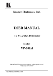
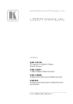
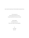
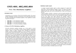
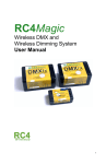
KRAMER ELECTRONICS, Ltd.
USER MANUAL
VGA/XGA Twisted Pair Transmitter and Receiver
Models:
TP-15
TP-16
IMPORTANT: Before proceeding, please read paragraph entitled
"Unpacking and Contents:"
Table Of Contents
Section
Name
Page
1
1.1
1.2
1.3
2
3
4
4.1
5
5.1
6
6.1
7
7.1
7.2
8
8.1
8.2
8.3
9
10
11
11.1
11.2
INTRODUCTION
A Word on Twisted Pair Interfaces
Handling Graphic Signals
Factor Affecting Quality of Results
SPECIFICATIONS
HOW DO I GET STARTED?
UNPACKING and CONTENTS
Optional Accessories
TWISTED PAIR LINE TRANSMITTERS AND RECEIVERS
Getting to Know Your TP-15 VGA/XGA Line Transmitter
INSTALLATION
How to Setup a Twisted-Pair System?
CONNECTING TO VGA/XGA SOURCE AND ACCEPTOR
Connecting to the Line Transmitter / Receiver
Effective Operating Range
USING THE VGA/XGA TWISTED PAIR SET
Powering On the Twisted Pair Set
Equalization Control
Additional Uses
TYPICAL VGA/XGA TWISTED PAIR LINK
TAKING CARE OF YOUR TWISTED PAIR MACHINES
TROUBLESHOOTING
Power and Indicators
VGA/XGA Signal
Limited Warranty
1
1
1
2
3
4
4
4
6
7
8
8
8
8
8
9
9
9
9
9
11
11
11
11
12
List Of Illustrations
Figure
1
2
3
Table
1
2
Page
TP-15 Front/Rear Panel Features
TP-16 FRONT/REAR PANEL FEATURES
TYPICAL VGA/XGA TWISTED PAIR SETUP
6
7
10
List Of Tables
TP-15 FRONT/REAR PANEL FEATURES
TP-16 FRONT/REAR PANEL FEATURES
6
7
ADDENDUM: Included with user manuals for machines with a CAT5 connector
This addendum describes the Power Connect feature used with Kramer
machines, and the choice between STP and UTP CAT5 cables.
Power Connect Feature1
The Power Connect feature lets you power a transmitter / receiver system by
connecting just one power adapter to either the transmitter or the receiver. The
other unit is fed over the same CAT5 cable.
The Power Connect feature applies as long as the CAT5 cable is heavy gauge
cable (that is, it can carry power). The distance does not exceed 50 meters on
standard cable.
For a distance of 100 meters, separate power supplies must be connected to the
transmitter and to the receiver simultaneously, unless using heavy gauge CAT5
cable.
Shielded Twisted Pair (STP) / Unshielded Twisted Pair (UTP)
The decision whether to use shielded twisted pair (STP) cable or unshielded
twisted pair (UTP) cable depends on the nature of the application.
It is recommended that in applications with high interference, shielded twisted
pair (STP) cable will give better results. However, the shield itself does create a
capacitance that degrades the frequency response of the machines. For shorter
distances, of 50m or so, shielded twisted pair (STP) cable is preferred because it
provides protection from interference (degradation is non-apparent).
For a long range application, unshielded twisted pair (UTP) cable is preferred.
However, the unshielded twisted pair (UTP) cable should be installed far away
from electric cables, motors etc., which are prone to create electrical interference.
1 This section of the addendum is only relevant to machines that support this feature (for example, the TP-104; not the
TP-100)
P/N: 2900 – 9999991
A1
INTRODUCTION
Congratulations on your purchase of this Kramer Electronics Twisted Pair equipment. Since 1981
Kramer has been dedicated to the development and manufacture of high quality video/audio
equipment. The Kramer line has become an integral part of many of the best production and
presentation facilities around the world. In recent years Kramer has redesigned and upgraded most of
the line, making the best even better. Kramer’s line of professional video/audio electronics is one of
the most versatile and complete available, and is a true leader in terms of quality, workmanship,
price/performance ratio and innovation. In addition to the Kramer line of high quality Twisted Pair
Interfaces, such as you have just purchased, Kramer also offers a full line of high quality distribution
amplifiers, switchers, processors, interfaces, controllers and computer-related products. This manual
includes configuration, operation and option information for the following products from the Kramer
line of Twisted Pair Interfaces:
TP-15 - Video Line Transmitter
TP-16 - Video Line Receiver
A Word on Twisted Pair Interfaces
Twisted Pair technology significantly simplifies studio and industrial wiring. The price of Twisted
Pair wire is far lower than that of coaxial cables, so it is attractive for many applications. The Twisted
Pair interfaces are divided into three families as follows:
Twisted Pair Transmitters - used to convert video, audio and PC generated VGA/XGA
signals to a twisted-pair signal format (balanced line). The twisted pair transmitters have useraccessible trimmers or controls for signal level and cable compensation.
Twisted Pair Receivers - used to convert a twisted pair format signal to video, audio or PC
generated VGA/XGA signals. The receivers have looping possibility; so several receivers may
be chained together on one twisted pair wire.
Twisted Pair Amplifiers - used to extend the operating distance of the twisted pair system, by
adding amplification and cable compensation along the twisted pair wire.
Handling Graphics signals
A computer generated graphics signal is usually composed of 5 signals: Red, Green, Blue - which are
analog level signals - and two TTL (logic) level signals - Horizontal Sync and Vertical Sync. (Digital
graphics cards and monitors use a different signal format, and will not be discussed here.) They are
called VGA, S-VGA, XGA, S-XGA and U-XGA, which are terms describing graphics resolution and
color depth. Computer graphics resolution is measured in pixels and signal bandwidth. The more
pixels (picture elements) on the screen, the more detailed the image. Color depth represents the
maximum number of simultaneously displayed colors on the screen and is measured in bits. 24 and
32-36 bits of color depth represent millions to billions of color shades available on the screen at any
given moment. It should be born in mind, though, that the human eye can resolve only a few
thousands colors! The more detailed the image (higher resolution) and the higher the color depth, the
more real the image will look. The highest resolution of standard VGA was 640x480 pixels with 4
bits of color (16 colors). Standard VGA was able to use more colors (256) but at a lower resolution around 320x200 pixels - which was very crude. Common resolutions used today for computer
graphics vary between 1024x768 and 2000x1600 pixels with “high color” - 16 bits of color
(representing 64,000 different colors) up to “true color” - 24 bits or more (representing from 16.7
million colors up to several billion.) Displaying such a detailed and colorful image on the screen
needs enormous graphics memory per frame, as well as very high speeds for “writing” so many pixels
on the screen in real time.
Amplifiers that carry such signals must be able to handle those speeds and signal bandwidths.
Standard VGA, at 640x480 resolution, needed amplifiers with 20-30MHz bandwidth. At 1600x1200
or even at 1280x1024 (S-XGA), such amplifiers will fail completely. In order to faithfully amplify
and transmit modern high-resolution graphics, amplifiers with bandwidths of 300 MHz and more are
needed. Those amplifiers, besides the enormous bandwidth they handle, need to be linear, to have
KRAMER ELECTRONICS LTD.
1
very low distortion and to be stable. Stability of an amplifier is its ability to avoid bursting into
uncontrolled oscillation, which is in adverse relationship to the speed it can handle. The tendency to
oscillate is further enhanced by the load impedance. The load impedance of a system is usually not
just a resistor. A cable connected to an amplifier (leading to the receiver or monitor) may present a
capacitive and/or inductive load to the amplifier. This is the main cause of instability. The poor
performance of a load or cable may severely degrade the performance of the amplifier - its bandwidth,
linearity, and stability - and in general its ability to faithfully reproduce the signal.
Cables affect image resolution. Longer cables can cause high frequency deterioration and hence
image “smear” and loss of resolution. In computer graphics especially, this adverse effect is very
much accentuated. Amplifiers should therefore also compensate for cable losses up to the maximum
useful operation distance. High-resolution graphics systems must use very high quality cables for
image transmission. The cables should be shielded - to eliminate externally induced interference
though the shield may increase the capacitance of the cable and, therefore, cause deterioration of
image resolution and clarity. Standard cables can only be a few meters long. For longer distances,
compound cable is separated into five individual coax cables, which are bulky and cumbersome for
use. Even so, the distance is limited to several tens of meters.
Cables may create other problems if they fail to accurately match the system’s required impedance.
The result of this, especially at high frequencies, is “shadows” or “ghosts” on the image, resulting
from standing waves and electronic reflections running back and forth between transmitter and
receiver. Another aspect to consider is the sync. As those signals are logic signals, which are not
treated as analog signals, the receiver does not terminate the line, and therefore the line is not
matched. A host of problems can occur when signals are sent over long, unterminated, unmatched
cables. The result can be image breakdown or distortion due to improper sync information. The
amplifier that drives the analog section of the graphics data should be able to buffer, recover and send
the sync information so that it will be received properly at the receiver end.
Factors Affecting Quality of Results
There are many factors affecting the quality of results when signals are transmitted from a source to
an acceptor:
Connection cables - Low quality cables are susceptible to interference; they degrade signal
quality due to poor matching and cause elevated noise levels. They should therefore be of the
best quality.
Sockets and connectors of the sources and acceptors - So often ignored, they should be of
highest quality, since "Zero Ohm" connection resistance is the objective. Sockets and connectors
also must match the required impedance (75ohm in video). Cheap, low quality connectors tend to
rust, thus causing breaks in the signal path.
Amplifying circuitry - Must have quality performance when the desired result is high linearity,
low distortion and low noise operation.
Distance between sources and acceptors - Plays a major role in the final result. For long
distances (over 15 meters) between sources and acceptors, special measures should be taken in
order to avoid cable losses. These include using higher quality cables or adding line amplifiers.
Interference from neighboring electrical appliances - These can have an adverse effect on
signal quality. Balanced audio lines are less prone to interference, but unbalanced audio should
be installed far from any mains power cables, electric motors, transmitters, etc. even when the
cables are shielded.
KRAMER ELECTRONICS LTD.
2
SPECIFICATIONS
TP-15
TP-16
Input
1 VGA/XGA - Analog R, G, B 0.7 Vpp/75 ohms, H, V syncs TTL
level on HD 15F connector
5 twisted pair sets, UTP on detachable
terminal block connectors.
Output
5 twisted pair sets, UTP on detachable 1 VGA/XGA - Analog R, G, B terminal block connectors.
0.7 Vpp/75 ohms, H, V syncs TTL
level on HD 15F connector
Video S/N ratio (SET)
71 dB
Bandwidth (SET)
245 MHz, -3dB (Red signal for example) @ 5m
Differential Gain (SET)
<0.09%
Differential Phase (SET)
<0.13 Deg.
Non Linearity (SET)
<0.3%
K-Factor
<0.05%
Controls
HF above 4.5MHz 0/+ 4.8dB, by front NA
control, triple EQ. network.
Dimensions
(W, D, H)
22cm x 18cm x 4.5cm
(8.6" x 7" x 1.8")
16.5cm x 12cm x 4.5cm
(6.5" x 4.7" x 1.8")
Weight
1.3 Kg. (2.9 lbs.) Approx.
0.7 Kg. (1.6 lbs.) Approx.
Power consumption
5.2 VA
4.6 VA
Power Source
230VAC, 50/60 Hz, (115VAC,
U.S.A.)
230VAC, 50/60 Hz, (115VAC,
U.S.A.)
KRAMER ELECTRONICS LTD.
3
HOW DO I GET STARTED?
The fastest way to get started is to take your time and do everything right the first time. Taking 15
minutes to read the manual may save you a few hours later. You don’t even have to read the whole
manual. If the section doesn’t apply to you, you don’t have to spend your time reading it.
UNPACKING and CONTENTS
The items contained in your Kramer Twisted Pair Transmitter/Receiver package are listed below.
Please save the original box and packaging materials for possible future shipment.
Twisted Pair Transmitter or Receiver
AC power cable
User Manual
Kramer Concise Catalog
4 rubber feet
Optional Accessories
The following accessories, which are available from Kramer, can enhance implementation of your
Line Amplifier/Kramer Tool. For information regarding cables and additional accessories, contact
your Kramer dealer.
Rack Adapter - Used to adapt smaller machines to a standard 1U rack. One or more machines
may be installed on each adapter.
BNC "Y" Connector - Used for looping purposes to split the incoming signal to enable
connection of an additional machine.
TP-17 – (VGA/XGA Twisted Pair Line Amplifier) for range extension of the TP-15/TP-16
system. This machine doubles the range of the TP-15/16 system, and provides an additional “local”
output.
VP-22 - (VGA / XGA Line Amplifier & Processor) can be serially inserted either between the
VGA/XGA source and the input of the TP-15, or between the output of the TP-16 and the input of
the VGA/XGA acceptor, for signal processing. It is a full bandwidth, looping Line Amplifier &
Processor, designed for computer and workstation applications where remote monitoring is needed.
The VP-22 splits VGA/Super VGA/XGA graphics card output to 2 remote monitors and allows the
user to control signal level and cable equalization for each channel independently. The machine
also allows control of horizontal and vertical sync delay on the BNC coaxial outputs. On its H/HV
SYNC output BNC, the VP-22 allows either horizontal or composite sync while on its green output
BNC, it allows either green or green + composite sync. State-of-the-art video amplifying circuitry
makes the VP-22 the perfect graphics component amplifier. Signal bandwidth of over 350MHz
allows it to be used with the highest quality graphics workstations.
VP-61RS - (6x1 VGA Switcher) can be serially inserted between the TP-15 input and several
VGA/XGA sources for source selection. It is a full bandwidth switcher, designed for computer and
workstation applications. The VP-61RS switches one of six VGA/Super-VGA/XGA graphics card
outputs to one monitor or vice versa, with no discernible signal degradation. The VP-61RS also has
RS-232 control. Input and output are direct coupled and conform to the highest standards. The
machine has a video bandwidth exceeding 180 MHz, suitable for graphics applications.
VP-101 - (VGA to RGBS Converter) can be serially inserted between the VGA/XGA output of
the TP-16 and an appropriate acceptor for VGA/XGA to RGB conversion. It is a full bandwidth
converter designed for computer, workstation and presentation applications. The VP-101 converts
a VGA/Super-VGA/XGA graphics card output to red, green, blue, horizontal/composite sync and
vertical sync. The signals are available on BNC connectors. Via a rear panel switch, the VP-101
allows the user to select either a composite or horizontal sync output. The composite sync
generated maintains the correct (negative) polarity at any polarity of Hs and Vs inputs. The input
and outputs are AC coupled conforming to the highest standards. The original source bandwidth is
retained to well over 300MHz thus allowing the VP-101 to be used with the highest quality
KRAMER ELECTRONICS LTD.
4
graphics workstations. The VP-101 is fed from a 12VDC source and is therefore suitable for
fieldwork as well.
VP-102 - (VGA to RGBS Converter) can be serially inserted between the VGA/XGA output of
the TP-16 and an appropriate acceptor for VGA/XGA to RGB conversion. It is full bandwidth,
especially designed for computer, workstation and presentation applications. The VP-102 converts
a VGA/Super - VGA/XGA graphics card output to red, green, blue, horizontal/composite sync and
vertical sync signals available on BNC connectors. The VP-102 allows the user to select either a
composite or horizontal sync output and the green output either includes composite sync or is
blanked. The composite sync generated by the machine is always at the right (negative) polarity for
any polarity of Hs and Vs inputs. Signal bandwidth of well over 315MHz allows the VP-102 to be
used with the highest quality graphics workstations.
VP-222 - (2x1 VGA switcher distributor) can be serially inserted between the TP-16 VGA/XGA
output and a VGA/XGA acceptor for VGA/XGA switching and distribution. The VP-222 allows
selection of one of two VGA/XGA sources and distribution of the selected source to two
independent outputs. Signal bandwidth of 365MHz ensures that the VP-222 remains transparent
even in the most critical applications. The VP-222 is part of the Kramer TOOLS family of
compact, high quality and cost effective solutions for a variety of applications. It is full bandwidth,
designed for computer and presentation applications.
VP-211 - (2x1 Automatic VGA/Audio Switcher) can be serially inserted between the TP-16
VGA/XGA output and a VGA/XGA acceptor. The VP-211 automatically detects the presence of a
VGA/XGA signal on input no. 1 and routes it to the output. If the signal disappears, the machine
will switch input no. 2 to the output. When the signal on input no. 1 re-appears, the VP-211
reroutes it to the output. The machine operates in audio-follow-video (VGA) mode and switches
the stereo audio input appropriate to the VGA input. Signal bandwidth of 517MHz ensures that the
VP-211 remains transparent even in the most critical applications. The VP-211 is part of the
Kramer TOOLS family of compact, high quality and cost effective solutions for a variety of
applications. It is full bandwidth, designed for computer and presentation applications.
VP-800 - (VGA/XGA Bar Generator) is one of the KRAMER TOOLS. It is a unique, high
quality color bar generator for testing and alignment of VGA/XGA equipment, such as monitors,
projectors, etc. The VP-800 generates a color bar, similar to a TV test pattern, in the four most
common resolution modes - 640x480, 800x600, 1024x768 and 1280x1024. Operation of the
machine is simple - just plug an appropriate power source into the DC socket, plug a VGA/XGA
cable to the "monitor OUT" socket leading to the acceptor (monitor, projector, etc.) and select the
desired resolution with one of the push switches. The VP-800 eliminates the need for a full
computer wherever a VGA/XGA signal has to be tested. It is DC fed, making it suitable for field
operation as well.
KRAMER ELECTRONICS LTD.
5
TWISTED PAIR LINE TRANSMITTERS AND RECEIVERS
This section describes all the controls and connections of the VGA/XGA Twisted Pair
Transmitter/Receiver. Understanding the controls and connections helps you realize the full power of
your machine.
Getting to Know Your TP-15 VGA/XGA Line Transmitter
The Kramer TP-15/TP-16 is set of VGA/XGA-to-twisted pair transmitter and receiver. The TP-15,
the transmitter, allows for cable equalization and signal amplification of the VGA/XGA signal, up to
distances exceeding 300 ft. (100 meters) using simple CAT5, unshielded wires (UTP). The machine
uses 5 pairs of wires, amplifying the analog RGB signals as well as stabilizing and correcting the
Horizontal and Vertical sync signals. The machines have detachable terminal block connectors for
easy connection and system wiring.
Front panel features of the TP-15 are described in Figure and Table 1.
Figure : TP-15 Front/Rear Panel Features
Table 1: TP-15 Front/Rear Panel Features
No.
1.
2.
3.
4.
Feature
Illuminated POWER switch
Cable EQ. Control
VGA/XGA IN connector
LINE out socket
5.
Power Connector
KRAMER ELECTRONICS LTD.
Function
Supplies power to the unit.
Controls cable equalization and allows for loss compensation.
The input of the machine from a VGA/XGA source (PC etc.)
Amplified and buffered balanced VGA/XGA output on
detachable terminal block connectors (5 pairs).
A 3-prong AC connector allows power to be supplied to the unit,
Directly underneath this connector a fuse holder houses the
appropriate fuse.
6
Getting to Know Your TP-16 VGA/XGA Line Receiver
The Kramer TP-15/TP-16 is a set of VGA/XGA-to-twisted pair transmitter and receiver. The TP-16,
the receiver, decodes the twisted pair signals, sent from the TP-15 transmitter, back to VGA/XGA
standard signals, appropriate for standard VGA/XGA acceptors. The machines have detachable
terminal block connectors for easy connection and system wiring.
Front panel features of the TP-16 are described in Figure 2 and Table 2.
Figure : TP-16 Front/Rear Panel Features
Table 2: TP-16 Front/Rear Panel Features
No.
1.
2.
3.
4.
Feature
Illuminated POWER switch
LINE IN socket
VGA/XGA OUT
Power Connector
KRAMER ELECTRONICS LTD.
Function
Supplies power to the unit.
The 5 twisted pair input to the receiver on terminal blocks.
The recovered VGA/XGA output signal on an HD15 connector.
A 3-prong AC connector allows power to be supplied to the unit. Directly
underneath this connector, a fuse holder houses the appropriate fuse.
7
INSTALLATION
The VGA/XGA transmitter and receiver can be rackmounted in a standard 19” (1U) EIA rack using a
special adapter (see section 4.1 "optional accessories"). Up to 2 machines may be installed on each
adapter. To mount machines in the rack, follow the instructions in the installation guide enclosed with
the adapter.
How to Setup a Twisted-Pair System
Twisted-pair wire system is very useful to transmit video, audio and VGA/XGA signals over long
distances. If a new system is designed, low capacitance, high quality twisted pair wires should be
selected for the job. If, however, you are trying to use existing twisted-pair wires already installed first verify the following:
The existing wires do not carry any voltage - direct or induced.
The existing wires have no "junctions" or breaks.
There is no short between the wires or link to "ground" along the wires.
For long distance operation it is recommended to use UTP (Unshielded Twisted Pair) type cables due to
their low capacitance, and low signal loss. For short distances – up to 10-20 meters - STP (Shielded
Twisted Pair) cables can be used for better protection.
Cables should be installed as close as possible to the ground or walls and far from antennas and electricity
cables to avoid lightning and EMP (Electro Magnetic Pulse), etc.
The cables between all the components leading to and from the acceptors and sources should be of precisely
the same length. If cable lengths are not equal, unwanted artifacts such as color smear and delay problems
(mis-registration of the black and white content with the color) may appear.
CONNECTING to VGA/XGA SOURCE AND ACCEPTOR
Connecting to the Line Transmitter / Receiver
VGA/XGA sources and output devices (such as monitors, projectors, etc.) are connected to the TP-15
and TP-16 through the HD15 connector located on the back panel. The twisted pair wire connecting
the transmitter to the receiver is a 5-pair wire set of the CAT5 type, preferably unshielded (UTP). The
LINE OUT socket on the TP-15 and the LINE IN socket of the TP-16 are marked with pin numbers.
Each connection (pin) number must be connected to the appropriate number on the pair unit, (pin 1 of
the TP-15 to pin 1 of the TP-16, etc.) Failing to do so may result in system malfunction. Color-coded
wires are recommended for easy identification.
Individual twisted pair sets (5 separate pairs) or combinations of wires such as a cable with two pairs
plus a cable of three pair may be used, as long as all wires have identical length.
Shielded cables, although “ protecting” the signals from external interference, may reduce the
effective range of operation of the system due to the inherent capacitance in those cables and hence
high frequency signal attenuation. As the signals involved in this system are very high frequency
(approaching 200 MHz and more), extra care should be taken when a decision is made as of which
cable to use.
!
!
The effective operating range for XGA (1024x768) PC graphics signals, using good, low capacitance
wires, is about 300 ft (100 meters). At VGA (640x480) and s-VGA (800x600) resolutions, the range
may be doubled. S-XGA (1280x1024) and UXGA (1600x1200) may have a shorter operating range.
It is very difficult to know best range at every resolution, as it is highly dependent on cable quality
and the settings used. The operation range may be easily doubled using a line amplifier such as the
Kramer TP-17, inserted in series with the twisted pair long line (at the remote location.) The TP-17
provides further line driving capacity as well as an extra local output. This “ local” output can be
driven with another TP-15 to a different location, creating a “ branch” in the system. Line amplifiers
may be cascaded to gain extra range, however, it is not practical to use more than two line amplifiers
in series.
KRAMER ELECTRONICS LTD.
8
"
USING the VGA/XGA TWISTED PAIR SET
"
Turning on the Twisted Pair Set
NOTES
1. The Twisted pair set should only be turned on
after all connections are completed and all source
devices have been turned on. Do not attempt to
connect or disconnect any signal to the Twisted
Pair set while it is on!
2. The socket-outlet should be near the equipment
and should be easily accessible. To fully
disconnect equipment, remove the power cord
from its socket.
1.
2.
"
Press the toggle switch of both the TP-15 and the TP-16 on the far-left front panel to the up position. In
the up position, the toggle switch glows.
Operate the acceptors.
Equalization Control
After the system is operational and all cables are connected, check the signal at the remote location. It
is preferable that a second operator, at the remote location (near the TP-16), instructs the operator
(using an intercom or a telephone) at the transmitting end, near the TP-15, how much to adjust the
cable EQ. Control. Visual testing is quite accurate, although it may be done more accurately using an
RF generator at the transmitting side (TP-15) connected to the RED, GREEN and BLUE inputs of the
HD15 connector, and having a spectrum analyzer connected to the RED, GREEN and BLUE outputs
of the HD15 connector of the TP-16. The user should adjust the control slowly till a flat frequency
response is achieved.
When a line amplifier is inserted in series with the twisted pair wire, it is necessary to adjust twice –
once near the line amplifier output, and the second time at the remote location.
For each and every different cable length or brand, the system should be re-tuned.
"
Additional Uses
The TP-15 and TP-16 set maybe used with signals other than VGA/XGA. Three analog signals (RED,
GREEN, BLUE) run at the machines, which may be used for YC, composite, and component video
signals (Y, R-Y, B-Y). In order to use the system for signals other than VGA/XGA, an appropriate
cable/adapter is needed between the HD-15 connectors and the plugs/sockets of the system. A typical
HD-15 to 5 BNC cable may be used to interface between the TP-15 and TP-16 and the BNCs of the
system.
The useful range for Composite, Y/C and Component video signals when using the TP-15/TP-16 set
is far bigger (more than triple) than the range for VGA/XGA signals due to the lower frequency
signals involved.
It should be born in mind that though the EQ. Control of the TP-15 equalizes the three usable
channels simultaneously, which is perfect for Component video use, it is not ideal if two different
signals (Composite and Y/C) are used together.
#
$%
& ' () '
*
%
+%
When it is necessary to transmit VGA/XGA signals over long distances and to distribute the signals to
remotely located users, as in presentation, schools, hospitals, airports, security applications and so on,
good quality VGA/XGA signals can be obtained using twisted- pair wires.
Figure illustrates a typical setup of Twisted Pair devices described in this manual: an incoming
VGA/XGA signal from a PC source is sent a over a long distance by the TP-15, using a 5-pair twisted
KRAMER ELECTRONICS LTD.
9
pair wire. The TP-16 VGA/XGA Line Receiver at the far edge of the wire receives the signal and
sends it to an acceptor. This figure also includes the optional line amplifier TP-17 used where an
extension of range is required.
The setup requires the following steps:
1.
2.
3.
4.
5.
Connect the output from the PC graphics card source to the Twisted Pair transmitter (TP-15).
Connect the output of the Twisted Pair transmitter to a 5-pair twisted cable.
Connect the TP-16 receiver at the remote end.
Connect a VGA/XGA acceptor to the twisted pair line receiver (TP-16) output.
Adjust received signal quality using the Cable EQ. control of the TP-15. If needed, insert a line
amplifier (TP-17) at the end of the twisted pair line for range extension.
Figure : Typical VGA/XGA Twisted Pair Setup
KRAMER ELECTRONICS LTD.
10
TAKING CARE OF TWISTED PAIR MACHINES
,
Do not locate your Twisted Pair device in an environment where it is susceptible to dust or moisture.
Both of these may damage the electronics, and cause erratic operation or failure. Do not locate your
Twisted Pair device where temperature and humidity may be excessive. Doing so may also damage
the electronics, and cause erratic operation or failure. Do not clean your Twisted Pair device with
abrasives or strong cleaners. Doing so may remove or damage the finish, or may allow moisture to
build up. Take care not to allow dust or particles to build up inside unused or open connectors.
TROUBLESHOOTING
NOTES:
Please note that if the output signal is disturbed or interrupted by very strong external electromagnetic
interference, it should return and stabilize when such interference ends. If not, turn the power switch off
and on again to reset the machine. If the following recommended actions still do not result in satisfactory
operation, please consult your KRAMER Dealer.
Power And Indicators
Problem
Remedy
No Power
For both models TP-15 and TP-16 perform the following:
1. Confirm that the rocker switch is in the “ ON” position, and that the LED
is illuminated.
2. Confirm that power connections are secured at the machine and at the
receptacle. Make sure the receptacle is active, outputting the proper mains
voltage.
3. Remove power cord from AC outlet and the machine and then, using a flat
head screwdriver, remove the fuse holder located directly below the power
connector on your machine. Confirm that the fuse is good by looking for
the wire connected between the ends of the fuse. If the wire is broken,
replace the fuse with another, with the same rating.
4. Install the cover by replacing the Philips screws.
VGA/XGA Signal
Problem
No VGA/XGA at the
output device, regardless
of input selected.
Remedy
1.
2.
3.
4.
VGA/XGA level is too
high or too dim.
1.
2.
3.
Confirm that your sources and output device are turned on and connected
properly.
Confirm that any other devices in the signal path have the proper input and/or
output selected.
Check if the twisted pair cables are connected properly, conforming to the
same pin number on both input and output.
Use the Kramer VP-800 (instead of the PC graphics card source) to check
whether the line and receiver are functioning properly.
Verify that the VGA/XGA line is properly connected on both sides.
Check whether there is no double loading on the input or output lines.
Readjust the TP-15 Cable EQ. control. Mis-adjustment of this control can
result in an apparent “ wrong” brightness image.
KRAMER ELECTRONICS LTD.
11
Signal quality
degradation: color is
weak or smeared, quality
of the picture is reduced,
and details of the picture
are lost.
Inappropriate cables usually have excessive built-in capacitance. When shielded
long cables are used, the capacitance grows thus causing the cable to pick more
interference from RF sources, such as transmitters, computers and other
appliances creating RF fields. These factors degrade signal quality due to high
frequency loss and interference pickup. Long distance between signal source and
the acceptors also affects the picture quality.
To solve the problem perform the following:
1. Use high quality non- shielded cables (UTP type) for the longer distances
(Multi Twisted Cable Wire is recommended).
2.
Use a line amplifier in series with the TP (such as the TP-17) to pre
compensate for signal degradation. You may cascade several line amplifiers to
extend the range.
3. Readjust the Cable EQ. control of the TP-15.
Problem
Remedy
Noise bars "roll" up or
down in the output image
or:
Low frequency Hum in
the output signal
Hum bars (ground loop) are caused by a difference in the ground potential of any two
or more devices connected to your signal path. Passing that voltage difference through
any available interconnection, including your video cables, compensates this
difference.
Check the following to remove hum bars:
1. Confirm that all interconnected equipment is connected to the same phase of
power, if possible.
2. Remove equipment connected to the phase that may introduce noise, such as
motors, generators, etc.
3. Disconnect all cables and reconnect them one at a time until ground loop
reappears. Disconnect the affected cable and replace, or insert an isolation device
(opto isolator or transformer) in the signal path.
LIMITED WARRANTY
Kramer Electronics (hereafter Kramer) warrants this product to be free from defects in material and workmanship
under the following terms.
HOW LONG IS THE WARRANTY
Labor and parts are warranted for three year from the date of the first customer purchase.
WHO IS PROTECTED
Only the first purchase customer may enforce this warranty.
WHAT IS COVERED AND WHAT IS NOT COVERED
Except as below, this warranty covers all defects in material or workmanship in this product. The following are not
covered by the warranty:
1. Any product which is not distributed by Kramer or which is not purchased from an authorized Kramer
dealer. If you are uncertain as to whether a dealer is authorized, please contact Kramer at one of the agents
listed in the web site www.kramerelectronics.com.
2. Any product, on which the serial number has been defaced, modified or removed.
3. Damage, deterioration or malfunction resulting from:
a) Accident, misuse, abuse, neglect, fire, water, lightning or other acts of nature, unauthorized
b) product modification, or failure to follow instructions supplied with the product.
c) Repair or attempted repair by anyone not authorized by Kramer.
d) Any shipment of the product (claims must be presented to the carrier).
e) Removal or installation of the product.
f) Any other cause, which does not relate to a product defect.
g) Cartons, equipment enclosures, cables or accessories used in conjunction with the product.
KRAMER ELECTRONICS LTD.
12
WHAT WE WILL PAY FOR AND WHAT WE WILL NOT PAY FOR
We will pay labor and material expenses for covered items. We will not pay for the following:
1. Removal or installations charges.
2. Costs of initial technical adjustments (set-up), including adjustment of user controls or programming. These
costs are the responsibility of the Kramer dealer from whom the product was purchased.
3. Shipping charges.
HOW YOU CAN GET WARRANTY SERVICE
1. To obtain service on you product, you must take or ship it prepaid to any authorized Kramer service center.
2. Whenever warranty service is required, the original dated invoice (or a copy) must be presented as proof of
warranty coverage, and should be included in any shipment of the product. Please also include in any
mailing a contact name, company, address, and a description of the problem(s).
3. For the name of the nearest Kramer authorized service center, consult your authorized dealer.
LIMITATION OF IMPLIED WARRANTIES
All implied warranties, including warranties of merchantability and fitness for a particular purpose, are limited
in duration to the length of this warranty.
EXCLUSION OF DAMAGES
Kramer’ s liability for any defective products is limited to the repair or replacement of the product at our option.
Kramer shall not be liable for:
1.
2.
Damage to other property caused by defects in this product, damages based upon inconvenience, loss of use of
the product, loss of time, commercial loss; or
Any other damages, whether incidental, consequential or otherwise. Some countries may not allow limitations
on how long an implied warranty lasts and/or do not allow the exclusion or limitation of incidental or
consequential damages, so the above limitations and exclusions may not apply to you.
This warranty gives you specific legal rights, and you may also have other rights, which vary from place to
place.
NOTE: All products returned to Kramer for service must have prior approval. This may be obtained from your dealer.
NOTICE
This equipment has been tested to determine compliance with the requirements of:
EN-50081:
EN-50082:
CFR-47
"Electromagnetic compatibility (EMC);
generic emission standard.
Part 1: Residential, commercial and light industry"
"Electromagnetic compatibility (EMC) generic immunity standard. Part 1:
Residential, commercial and light industry environment".
FCC Rules and Regulations:
Part 15- “ Radio frequency devices:
Subpart B- Unintentional radiators
CAUTION!
Servicing the machines can only be done by an authorized Kramer technician. Any user who
makes changes or modifications to the unit without the expressed approval of the manufacturer
will void user authority to operate the equipment.
Use the supplied DC power supply to feed power to the machine.
Please use recommended interconnect cables to connect the machine to other components.
KRAMER ELECTRONICS LTD.
13
For the latest information on our products and a list of
Kramer distributors, visit our Web site:
www.kramerelectronics.com.
Updates to this user manual may be found at
http://www.kramerelectronics.com/manuals.html.
We welcome your questions, comments and feedback.
Kramer Electronics, Ltd.
Web site: www.kramerelectronics.com
E-mail: [email protected]
P/N: 2900-007015 REV 2