1
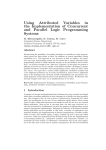
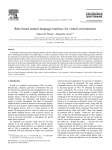
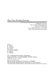
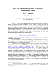
Interfacing Prolog and VRML and its Application to
Constraint Visualization∗
Göran Smedbäck
[email protected]
Computer Science Department
Uppsala University
Box 311, 751 05 Uppsala, Sweden
Manuel Carro, Manuel Hermenegildo
{mcarro, herme}@fi.upm.es
Computer Science School
Technical University of Madrid
Boadilla del Monte, 28660 Madrid, Spain
Fax: +34-91-336-7412
Abstract
A number of data description languages initially designed as standards for the WWW are currently being used to implement user interfaces to programs. This is done independently of
whether such programs are executed in the same or a different host as the one running the user
interface itself. The advantage of this approach is that it provides a portable, standardized,
and easy to use solution for the application programmer, and a familiar behavior for the user,
typically well versed in the use of WWW browsers. Among the proposed standard description
languages, VRML is a aimed at representing three dimensional scenes including hyperlink capabilities. VRML is already used as an import/export format in many 3-D packages and tools,
and has been shown effective in displaying complex objects and scenarios. We propose and
describe a Prolog library which allows parsing and checking VRML code, transforming it, and
writing it out as VRML again. The library converts such code to an internal representation
based on first order terms which can then be arbitrarily manipulated. We also present as an example application the use of this library to implement a novel 3-D visualization for examining
and understanding certain aspects of the behavior of CLP(FD) programs.
Keywords: Execution visualization, Constraint Logic Programming, Constraint Programming,
Prolog, VRML.
1 Introduction
An increasing number of applications are using Internet and WWW-related techniques and tools as
standard user interfaces. Browsers (and applet viewers) are now often used not only for web surfing
∗
This work has been partially supported by ESPRIT LTR project DISCIPL # 22532 and by CICYT TIC 97-1640CE. Göran Smedbäck was partially supported by an HCM/TMR grant associated to the project ABILE, ERBCHRXCT
940624.
Figure 1: A cylinder generated from VRML code.
and as interfaces to web-based applications, but also as front-ends for more standard applications
which typically run locally in a single host. From the user point of view, this approach has the
advantage that it provides a homogeneous and familiar “look and feel” across programs and even
operating systems. Such homogeneity can play a key rôle in the success of a user interface since it
makes interacting with different applications easier for the average user. Additionally, this approach
offers a portable, standardized, and easy to use solution for the application programmer.
Depending on the complexity of the interaction required by the application, practical user interfaces can be implemented even with the basic Hypertext Markup Language (HTML) [2]. A typical,
basic interaction scheme can be described as follows: the application generates an HTML page that
is displayed in a browser and which prompts the user for some input via menus, maps, buttons, etc.
The application then processes the input from the user and responds with a new HTML page. The
output from the program can range from tables and results of a search to figures, graphs, etc., and
can also prompt again for some more user input. This whole process can be implemented through
the use of a CGI gateway, which reads some input from the user, and generates a new page according to this input. More recent extensions of HTML, such as Dynamic HTML (DHTML) [6]
or the Virtual Reality Modeling Language (VRML) [14], and even the embedding of programming
languages into WWW pages1 , increase the power of this approach, by providing, for example, local
execution of complex application front ends and data filters, more interactive pages, dynamic update, and more elaborated graphical facilities, including 3-D. Coupling such extended description
languages with the automatic generation of pages opens interesting possibilities, including more
sophisticated interfaces, better performance, and greatly simplifying the actual generation of the
page, since the program which creates it is relieved from part of the work involved.
Another quite interesting task is the implementation of what is in some ways a dual of the
scenario presented above: being able to fetch WWW pages (local or remote) and parse their contents. This is useful for many applications: WWW robots perform this task routinely, analyzing
such pages in order to, for example, distinguish between an image and a header. Sophisticated
applications require not only reading and identifying the keywords of a WWW page, but also recovering its structure, so that the logical layout of the page can be understood. This allows treating
its components as separate units and manipulating them independently of each other.
1.1 VRML and other alternatives for 3-D representation
In this paper we are interested in 3-D representations, required by some of the the applications that
we have in mind, which include the visualization of constraint program execution we present as
an example in Section 3. We concentrate on VRML, which seems to be an increasingly popular
1
Such as Java or even Java-based Prolog interpreters [7].
graphical description language in this context. VRML code describes 3-D scenes, using either
predefined objects or user-defined ones (see Figure 1 for a simple example). Hyperlinks and actions
can be associated to objects, which can be clicked on in order to jump to the location referred to
by the object or to download information linked to it. This allows remote access to VRML worlds,
surfing inside VRML worlds, and even using them as user interfaces, in a similar way as it is done
usually with standard HTML.
Up to now VRML code has been typically viewed with specialized browsers, but general WWW
browsers are now including support for this data format. Quite complex levels of interaction with
VRML scenes, such as navigation, rotation, shading, following hyperlinks, etc., are handled locally
by the browser. This is clearly a great advantage in that it considerably simplifies the task of
displaying and manipulating three dimensional models in a portable and uniform way, and without
having to pay attention to low-level operations.
There are several alternative approaches to using VRML for 3-D interfaces. In principle, a 3-D
scene can be rendered into an image file and included in a standard HTML page. This image can
even be configured as an active map so that certain parts are associated to hyperlinks. However,
this approach does not allow manipulation and navigation of the 3-D structure of the scene at the
browser side, and is thus quite limited. DHTML can be used to achieve greater control over the
appearance, layout and behavior of Web pages. DHTML allows parts of the page to remain hidden
(pictures included) until an action is performed by the user. The page then changes its layout in
response to this action. While this facility can be used to achieve richer graphical interaction, it is
really not designed for representing 3-D scenes and shares most of the limitations pointed out for
HTML.
Another alternative is to use general purpose languages, such as Java or ActiveX controls, which
allow introducing arbitrary complexity in WWW pages. Java, as a general-purpose programming
language for which most browsers have native support, allows programs to be executed in WWW
pages as “applets”. This can add high levels of functionality to such pages, including graphics, animation, and 3-D scene representation and manipulation (specific classes for that purpose have been
released lately). However, because it is a full programming language, reading and understanding
Java programs cannot be easily automated. Generating Java automatically is, of course, possible, but reading a page containing arbitrary Java code which creates a 3-D scene with embedded
actions and being able to understand the scene (identifying the objects and interactions) in order
to manipulate it automatically is non-trivial. ActiveX, Microsoft’s standard interface for sharing
objects within a Windows environment, shares, from our point of view, many characteristics with
Java. An ActiveX control is roughly comparable to a Java applet, presenting similar advantages
and drawbacks.
Using VRML as the target description language has the advantage that it offers a standardized,
declarative representation of 3-D objects and the actions associated with them, which is relatively
simple to parse and process automatically. Additional advantages are its conceptual simplicity, the
flexibility it offers, and the fact that there are a number of 3-D design tools which have already
adopted VRML as a de facto standard, and which can export and import files in this format.
1.2 Manipulating VRML code
One drawback of VRML, shared with other related description languages, is that it is somewhat
low level to be routinely processed. Thus, we will be interested in tools which allow manipulating
VRML code at a higher level. Among them, we are interested in those which offer the possibility
of creating new pages, either from scratch or using existent VRML code as source. Thus, tools
which only visualize VRML are not considered in our discussion. We will also not consider tools
Parsing
HTTP access
VRML
Transformation
Datastructure
Translation
Datastructure
Source code
VRML
Code produced
Generation
Figure 2: Different stages in the automatic manipulation of VRML code.
which are simple file translators between other 3-D modeling formats (such as Inventor, AutoCAD,
etc.) and VRML2 .
1.2.1 Interactive graphical design tools
A number of graphical tools are available which allow creating, reading, rendering, modifying, and
writing out VRML code. They offer a wide range of operations which are quite useful for generating and modifying VRML scenes in an interactive way. However these tools usually suffer from
one or more drawbacks for our purposes. Many of these programs are themselves graphical, and
intended for an interactive use, and typically they cannot be programmed to generate VRML scenes
automatically from input data. This feature is needed, for example, in interactive applications, e.g.,
by programs which need to depict output data using VRML. Even in the cases where such tools
include a programming language, it is typically not flexible enough: in general, we need a language
with more capabilities than just graphical commands, in order to process the input data and to create VRML code which represents it. On the other hand these tools can be extremely useful for
the graphical design of basic background scenes and component objects which can then be used as
building blocks in other approaches.
1.2.2 Representing VRML objects as structures
An alternative is, while still using VRML for the representation of 3-D scenes, to apply a more
general purpose language for the manipulation of such scenes. While a program can in principle
manipulate VRML code segments directly as strings, an arguably better approach is to represent
the VRML code internally in a more structured way. Most of the information contained in the
VRML code is just a logical, structured listing of the objects in the scene and the relationships
among them. Therefore, it seems natural to map such objects into internal data which mirrors
that structure, i.e., to reflect the hierarchy and internal relationships of the VRML code into native
data structures of the programming language. Once this mapping has been performed, these data
can be easily manipulated within the host language. Such a representation facilitates not only the
automatic creation of VRML pages from scratch, but also reading, inspecting, transforming, and
finally generating VRML code.
Figure 2 shows, schematically, possible paths which can be taken with this approach. VRML
code can be read from a local file or from the net, its contents reflected as an internal data structure, processed, and output again as VRML code. The essential components are a VRML parser
which can convert VRML code into the above mentioned internal data structures, a pretty-printer
capable of converting the internal data structures back into VRML code, and, possibly, a number of
2
See a listing of some of them at http://www.ocnus.com/translate.html
functions implementing transformations on the internal data structures representing the VRML objects. Additionally, an implementation of the HTTP protocol can be used to access remote VRML
code. These components can typically be implemented in the form of a library, and constitute the
building blocks of many applications:
• Checking the code read for conformance to the VRML standard specifications during the
parsing process.
• Checking for the existence of some elements in the scene. For example, following the links
in a VRML model to test existence or reachability of a certain object, or listing which objects
appear in that scene. These are tasks routinely performed by WWW robots, and benefit from
a high-level representation of the scene.
• Extracting objects from the scene, in order to, for example, use them in other scenes.
• Performing operations on scenes, such as addition or intersection.
• Making arbitrary changes in scenes. This, in simple cases, can be made by traversing the
data structure and adding/removing/modifying components to/from it or modifying shapes,
textures, colors, etc.3
1.2.3 Choosing a host language
While any host language can in principle be used, the presence of certain characteristics makes the
task much easier. A number of special-purpose languages have been proposed in the context of
VRML. An example is IVL [13], an interpreted language whose purpose is to allow defining scenes
in a more user-friendly fashion than writing raw VRML. It appears that some of these languages
are not computationally complete, which makes arbitrary processing of VRML code impossible.
In any case, because they are designed specifically for this purpose, using them implies that a new
language needs to be learned just for this task. Also note that Internet-related input/output facilities
(e.g., I/O on sockets) are also often needed for certain types of tools.
With respect to more general-purpose languages, note that the general approach chosen (Figure 2) implies that operations on the VRML code will be performed on the data structures of the
chosen language. This language should therefore have rich enough internal data structures and
extensive symbolic processing capabilities to represent and manipulate in a direct way complex
VRML objects. This makes many (scripting) languages which are widely used in Internet-related
applications, such as classical shell languages (sh, csh, etc.), Tcl, and Perl 4 less attractive. Also,
since the number and size of the objects is in many cases unknown a priory, dynamic memory management is highly desirable. Some widely-used general-purpose languages, such as C or, specially,
C++, offer rich data structures and dynamic memory allocation and are certainly an option, and a
number of libraries have been developed for such languages. For example, OpenWorlds [5] is a
(commercial) set of C++ libraries which provide parsing, scene-graph traversal, routing, scripting,
prototyping, and external interfaces.
However, higher-level languages with automatic garbage collection, such as functional and
(constraint) logic languages or Java are often better choices, simplifying not only the development
of the library but also the user programs which use it, as well as making it much easier to add
capabilities needed in an application and which are not provided directly by the library. Libraries
3
4
See Section 2 for an example of this.
However, note that after version 5 Perl now includes support for explicit references.
for VRML manipulation in Java are already available (the syntax and design of VRML itself is in
fact related to that of Java), as well as for some functional programming languages. For example,
VRML Generation [9] is a set of tools written in Lisp for VRML generation and designed to be
incorporated into the CL-HTTP5 server. There has also been related work on the creation of and
interaction with virtual worlds with Prolog [10].
Our particular interest in this paper lies in the use of Prolog (and other constraint logic languages) as the host language. We will report on the development of a library for interfacing Prolog
and VRML. This is interesting in itself in that it is the most natural way to provide a means for
adding a VRML interface to existing Prolog applications. However, we argue also that Prolog
offers a number of characteristics which make it quite suitable as a VRML processing language:
• Writing (recursive descendent) parsers in Prolog is straightforward, thus making the task of
implementing the first stage of the tool quite simple; modifying such parsers in order to keep
up to date with possible changes in the definition of VRML is also very easy.
• Easy mapping of structures: due to the way data structures are handled in Prolog, reflecting
VRML code into Prolog data structures boils down to assigning names to functors, corresponding to those in the VRML nodes.
• Easy manipulation: Generating, handling and transforming such data structures is simple
(see Section 2), and can in many cases be done by using code templates the higher-order
predicates and meta-programming facilities that Prolog offers.
• Suitable input/output capabilities: Prolog offers input/output facilities similar to those found
in other high-level programming languages, and communication using sockets is available in
most modern Prolog implementations. Implementing the HTTP protocol based on that is not
difficult — additionally, an implementation is available as part of the public domain Pillow
library [3]. This makes interacting with the net (e.g., reading VRML code at URL addresses)
an easy task.
2 Interfacing (Constraint) Logic Languages and VRML
We now describe the library that we have developed for interfacing Prolog (and other constraint
logic languages) and VRML: ProVRML. In Section 3 we will present, as an example application
of the library, a tool which implements a novel 3-D visualization of certain aspects of the execution
of constraint logic programs using finite domain constraints.
2.1 Representing VRML as Prolog Terms
The representation of VRML as terms follows a few general principles:
• VRML names translate directly to functors.
• A VRML structure whose body may contain a variable number of elements is represented
by a structure with a functor of arity 1 and whose single argument is a list, containing the
VRML terms corresponding to each element.
5
http://www.ai.mit.edu/projects/iiip/doc/cl-http/home-page.html
#VRML V2.0 utf8
Transform {
rotation 1 0 1 0.71
translation 0 0 0
children
Shape {
geometry Cylinder {
height 2
radius 0.6
}
appearance Appearance {
material Material {
diffuseColor 0.97 1 0
}
}
}
}
[’#VRML V2.0 utf8’,
’Transform’([
rotation(1,0,1,0.71),
translation(0,0,0),
children(
’Shape’([
geometry(’Cylinder’([
height(2),
radius(0.6)
])),
appearance(’Appearance’([
material(’Material’([
diffuseColor(0.97,1,0)
]))
]))
)
])]
Figure 3: VRML code (left) and the corresponding Prolog VRML term (right).
• A VRML structure whose body contains a fixed number of elements N is represented by a
structure with a functor of arity N and whose N arguments are the VRML terms corresponding to each element.
This is essentially the same approach used in the Pillow library [3] for representing HTML structures as Prolog terms.
The actual mapping is best understood by looking at an example. Figure 3, left, shows the
VRML code for the cylinder depicted in Figure 1. The corresponding Prolog VRML term is presented in Figure 3, right. The correspondence in structure and appearance between the VRML
terms and the VRML code should be clear. This similarity makes it possible to use knowledge of
VRML to understand and perform operations on a VRML term, with little or no additional learning.
2.2 VRML Templates
The use of Prolog terms to represent VRML code opens an interesting possibility: using VRML
terms with free variables inside (possibly bound among them) to represent generic data (templates)
of objects or scenes. These VRML templates are extensions to VRML terms which allow associating an atomic name to a “hole” in a VRML object. A VRML template is a pair template(IVRMLTerm,Dict), where IVRMLTerm is an “incomplete” VRML (IVRML) term.
I.e., it is a non-ground term containing a number of variables V 1 . . . Vn . Dict is a dictionary
which associates the variables V1 . . . Vn with an equal number of names (which are Prolog atoms),
N1 . . . Nn . Each name corresponds to an instance of a special kind of object (’handle’) which appears in the VRML code, and whose unique identifier is that name — thus VRML templates can
have a direct counterpart in plain VRML code. The idea behind VRML templates is that a template
may describe a scene in which there is a missing object, to be added later, or for which a certain
characteristic (such as color or texture) will be defined at a later time. These templates can as well
be used as a repository of generic or user-defined objects with some characteristics unspecified, i.e.,
with holes on them. These holes can be filled in by accessing dictionary associated with the object,
looking up the relevant keyword, and instantiating the (free) variable. Fields having a default value
can be left uninstantiated (if that default value is not to be overridden).
2.3 The VRML Parser and Pretty Printer
One of the main objectives of the ProVRML library is to provide facilities for reading and parsing
VRML pages into VRML terms, and translating VRML terms into VRML code again. The latter
task is quite simple and is implemented by a simple pretty printer. The task of reading VRML
pages is done using the standard input predicates of ISO-standard Prolog in the case of reading
from local files or standard input. If the VRML code resides at a URL address, then the public
domain implementation of the HTTP protocol available as part of the Pillow [3] library is used.
The actual conversion of a character string containing VRML code into VRML terms is performed by what is one of the main components of ProVRML, a recursive descendent parser implemented using a Prolog DCG grammar [1]. This grammar is essentially a direct encoding of
the VRML definitional grammar [15], augmented with additional arguments and rules to facilitate
error handling and recovery.
A first stage scans the VRML code and outputs tokens according to the rules for identifiers
and numbers in the VRML specification [15]. Then, the parser analyzes these tokens in order to
generate the internal representation, i.e., the Prolog VRML terms of Figure 3, right.
2.4 Error Detection and Handling
The goal of error detection and handling is to find as many syntactic and semantic errors as possible
during the processing of VRML code. Error detection is made both when reading (in order to check
for ill-formed VRML data) and when writing VRML structures (to check for data structures which
have not been correctly generated). No error correction is attempted by ProVRML, but some nonfatal errors are ignored.
During the first step, the tokenization, some syntactic errors in the basic constructions are detected, and malformed code is rejected. The parser will then complete the checking of syntactic
errors, and will also recognize some semantic errors, such as values of wrong type in some fields,
type mismatches, and wrong node descendants.
Syntactic and semantic errors can also appear when generating VRML code from Prolog terms.
Valid Prolog terms can represent wrong VRML code due to, for example, wrong type values in
fields or wrong node descendants. The pretty printer tries also to detect as many errors as possible.
Semantic errors may be detected as well when performing checks of field names and node values:
for example, trying to connect items of two different types will result in the explicit message that
linking them is impossible. All field values will be compared against their type to check type
correctness, and all numerical values will also be checked to ensure that they are within their limits.
References to undefined nodes or fields will be detected, as well as references to unreachable nodes.
All errors, except violation of boundary errors, will lead to immediate abortion of the processing
and issuing the corresponding error message, unless the corresponding exception is caught by the
calling program. Boundary errors will be noted but ignored if possible, even if this can result in an
erroneous rendering of the VRML scene.
2.5 The vrml Library Interface
As mentioned previously, ProVRML is implemented as a Prolog library (vrml) which provides a
number of top level interface predicates. A first set of predicates give access to the tokenizer/parser
and the pretty-printer:
vrml to terms(VRMLCodeString, ListOfTerms) :
Converts a string of VRML code in VRMLCodeString to a list of (I)VRML terms in
ListOfTerms. This is the entry point to the tokenizer/parser.
terms to vrml(ListOfTerms, VRMLCodeString) :
Converts a list of (I)VRML terms to a string of VRML code. This is the entry point to the
pretty printer.
terms vrml(ListOfTerms, VRMLCodeString) :
Bidirectional version of the above. Calls vrml to terms or terms to vrml depending
on whether ListOfTerms or VRMLCodeString is a free variable.
The following auxiliary predicates are abstractions above the previous ones which include file
or URL access:
vrml http access(URL, VRMLCodeString) :
Accesses the content of a URL (which should be pointing to a VRML scene) and returns the
code in VRMLCodeString.
vrml file to terms file(VRMLFile, TermFile) :
Converts the VRML code in VRMLFile to terms and writes them to TermFile. Note that
TermFile can then be easily read/1 using ISO-standard Prolog primitives.
terms file to vrml file(TermFile, VRMLFile) :
Converts the Prolog terms representing VRML code in TermFile to VRML code and writes
it to VRMLFile.
vrml file to terms(VRMLFile, ListOfTerms) :
Converts the VRML code in VRMLFile to the list of VRML terms ListOfTerms.
terms to vrml file(ListOfTerms, VRMLFile) :
Writes the VRML code corresponding to ListOfTerms to the file VRMLFile.
vrml to terms file(VRMLCodeString, TermFile) :
Converts a string of VRML code to a file with terms.
terms file to vrml(TermFile, VRMLCodeString) :
Converts terms from a file to a string of VRML code.
The implementation of the library does not make use of non ISO-Prolog primitives (the implementation of the HTTP protocol is encapsulated in a separate library). Thus, the library should be
portable effortlessly to any Prolog or CLP dialect with relative ease.
:- module(change,[change/2]).
:- use_module(vrml).
change(InFile,OutFile) :vrml_file_to_terms(InFile,TermsIn),
cylinders_to_cones(TermsIn,TermsOut),
terms_to_vrml_file(TermsOut,OutFile).
cylinders_to_cones([],[]) :- !.
cylinders_to_cones(In,In) :atomic(In), !.
cylinders_to_cones([First|In],[First_cone|Out]) :- !,
cylinders_to_cones(First,First_cone),
cylinders_to_cones(In,Out).
cylinders_to_cones(’Cylinder’(Fields),’Cone’(ConeFields)) :- !,
convert_fields(Fields,ConeFields).
cylinders_to_cones(Node,NewNode) :compound(Node),
Node =.. [Name|Guts],
cylinders_to_cones(Guts,NewGuts),
NewNode =.. [Name|NewGuts].
convert_fields([],[]).
convert_fields([Cylinder_field|Cylinder_fields],
[Cone_field|Cone_fields]) :field(Cylinder_field,Cone_field),
convert_fields(Cylinder_fields,Cone_fields).
field(radius(R),bottomRadius(R)).
field(height(H),height(H)).
field(bottom(B),bottom(B)).
field(side(S),side(S)).
Figure 4: Prolog code to change cylinders to cones in any VRML file.
Figure 5: The scene to be transformed.
Figure 6: The scene after the change.
2.6 Generating and Modifying VRML Code
It is straightforward to generate VRML scenes automatically under program control using the library primitives. Such scenes can be built incrementally as VRML terms and then converted into
actual VRML code. The possibility of inserting logic variables in place of some terms or arguments
allows building objects with “holes” and/or undefined characteristics. These logic variables can be
instantiated at a later time setting the undefined arguments or adding component objects, and thus
building more complex, nested objects and scenes.
Alternatively, VRML code can be read into the program and then manipulated. As an example
of this, the Prolog program in Figure 4 can read any VRML scene contained in InFile and
generate a new file OutFile in which all cylinders have been changed to cones. Predicates in the
vrml library are used to parse the VRML code into Prolog terms and to write the newly generated
structure again to a file. The code in this example just traverses the structure and, when a cylinder is
found, it is changed to a cone, updating the fields in its definition. This piece of code can be taken
as a template for other similar operations — and even transformed into a higher order predicate.
An example of the results of applying this code is the transformation of the scene in Figure 5 to the
scene in Figure 6, which was done automatically.
In practice, it appears that a combination of these techniques (reading, modification, and output
of VRML) is most useful. For example, an interactive 3-D design tool can be used to create a background scene and a number of basic elements (which would otherwise be very tedious to generate
by hand). An animation program can then read these elements perhaps placing and even moving
several instances of the different basic elements, with different characteristics, on the background.
3 An Example Application: CLP(FD) Visualization
Visualization of CLP executions is receiving much attention recently, because of its application to
program debugging, both in terms of correctness and of performance (see [4] and its references).
Representing certain characteristics of CLP execution is quite challenging. One important difference between CLP and other paradigms is the fact that each variable can represent a (possibly
infinite) set of values, and that there are constraints attached to such variables which relate them
and restrict their domains. These relationships may be inferred by inspecting a textual dump of the
constraints and variables, probably using the source code representation. Unfortunately this is not
straightforward or even possible in some constraint systems, and, even when it is possible, it typically provides too much level of detail for an intuitive understanding. Most of the characteristics
of interest will very probably remain hidden under too much irrelevant information.
An interesting alternative, and which is pertinent to our application, is to use graphical representations of selected information: different visualizations can be designed to focus on the different
characteristics to be studied, such as the amount of search performed, the relationships among variables, etc. For the sake of concreteness, and because of its practical importance, we will focus our
discussion on performance debugging of CLP(FD) programs, i.e., programs using Finite Domain
constraints [11, 8]. One way to understand the performance behavior of a CLP(FD) program is by
following the history of the execution of the program. This can be done by representing how the
values of the variables change as the program proceeds [12, 4]. The graphical representation can be
animated (i.e., time in the program is represented also as time in the visualization), but in practice it
is often more useful to have a static picture in which time is represented by some spatial axis—this
allows to grasp at a glance the “big picture” of the execution over the time. A number of such
representations can be found in [12, 4]. In most cases, however, showing all the possible values
of the variables, as well as the time axis, can result in a view that is too complex to be intuitively
Y
X The CLP(FD) variables.
X
Y An abstraction of the variable: the size of its domain.
Z Time.
Z
Figure 7: Meaning of the dimensions in the 3-D representation.
:- use_module(library(clpfd)).
:- use_module(user_labeling).
dgr(WhichOrder, ListOfVars):ListOfVars = [D,O,N,A,L,G,E,R,B,T]
open_log_file(dgr, FileHandle),
order(WhichOrder, ListOfVars, OrderedVars),
domain(OrderedVars, 0, 9),
log_variables(OrderedVars, FileHandle),
D #> 0,
log_variables(OrderedVars, FileHandle),
G #> 0,
log_variables(OrderedVars, FileHandle),
all_different(OrderedVars),
log_variables(OrderedVars, FileHandle),
100000*D + 10000*O + 1000*N + 100*A + 10*L + D +
100000*G + 10000*E + 1000*R + 100*A + 10*L + D #=
100000*R + 10000*O + 1000*B + 100*E + 10*R + T,
log_variables(OrderedVars, FileHandle),
user_labeling([], OrderedVars, Filehandle).
%% Added
%% Added
%% Added
%% Added
%% Added
%% Added
%% Added
order(1, [D,O,N,A,L,G,E,R,B,T], [D,G,R,O,E,N,B,A,L,T]).
order(2, [D,O,N,A,L,G,E,R,B,T], [G,O,B,N,E,A,R,L,T,D]).
Figure 8: The annotated DONALD + GERALD = ROBERT FD program.
understood.
Herein, we propose to use a 3-D visualization, using the VRML interface presented in the
previous sections, in order to gain one more dimension in such representations. We will represent
the values taken by a (selected) number of finite domain variables in the program during execution.
For the depiction of the values taken by each variable we will use a very simple representation
(abstraction): instead of highlighting which values are (possibly) inside the domain of a variable,
as in [12, 4], we will represent only the number of values (i.e., the size of the current domain at
each step) that a given variable has available. The domain size at the beginning of the execution is,
obviously, the largest the variables can have.
Figure 9: Execution of the DONALD + GERALD = ROBERT program, first ordering.
We will show a couple of examples of this representation. Figure 8 shows a CLP(FD) program
for the problem DONALD + GERALD = ROBERT (which is similar to the SEND + MORE =
MONEY puzzle, but with a larger search space). As any CLP(FD) programmer knows, different
orderings of variables will change the size of the search until the first solution is reached. In this
example two possible orderings have been preselected (using the order/3 predicate), and a visualization of their execution is shown in Figures 9 and 10. The meaning of each of the dimensions
in these representations is explained in Figure 7: time runs along the Z axis, and every row along
this dimension corresponds to a snapshot of the set of FD variables which have been selected for
visualization. In each of these rows, the size of the domain of the variable (according to the internal
representation of the solver) is depicted as the dimension Y.
Programs to be visualized have to be annotated with calls to predicates which save (in a trace
file, for example) the sizes of the domains of each variable at the time of each call to such predicates.
The predicate user labeling/2 is a version of the labeling/2 predicate which logs the
domains of the variables after every choice is made. This information is unaffected by backtracking
because it is saved externally, and thus it contains information relevant to the number of choices
made during the execution. The resulting log file is then processed by a Prolog program which
converts it to a ProVRML data structure, and saves it as a VRML file. This can be rendered with a
VRML viewer, rotated, zoomed in and out, etc.
Note that this process could be made “monolithically”: the information about the sizes of the
domains of the variables could have been saved to the internal database (to protect them from
backtracking), and then recovered and processed directly. However, an intermediate trace file may
be useful for different purposes (e.g., analyzing other characteristics of the execution), and thus it
makes sense to store it separately with the aim of reusing it without having to rerun the program.
Figure 9 is an execution of the program in Figure 8 using the first ordering of the variables.
The variables closer to the origin (the ones which are labeled before) are assigned values quite
soon in the execution and they remain fixed. But there are backtracking points scattered along the
execution, which can be seen as blocks of variables protruding from the picture. There is also a
variable (which appears as a white strip in the middle of the picture) which appears to be highly
constrained, so that its domain is reduced right from the beginning. That variable is probably a
good candidate to be labeled soon in the execution. The rest of the variables apparently have a high
Figure 10: Execution of the DONALD + GERALD = ROBERT program, second ordering
interdependence (at least, from the point of view of the solver), because in case of backtracking,
the change of one of them affects all the others. This suggests that there are two different sets
of variables in this problem from the point of view of the behavior of the constraint solver: one
which contains variables highly interdependent (those whose domains change at once in the case of
backtracking) and a second one which contains variables relatively independent from those in the
first set.
Other execution of the same program, using the second ordering, yields the profile drawn in
Figure 10. Compared to the first one, there are fewer execution steps, but, of course, the classification of the variables is the same: the whole picture has the same general layout, and backtracking
takes place in blocks of variables.
Another example is the well-known queens program. A CLP(FD) version is shown in Figure 11,
and the execution, with the same interface as in the Figures 9 and 10, is represented in Figure 12.
Compared with the previous two programs, the domains of the variables in this problem are reduced quite quickly, and the enumeration process performs only a limited amount of backtracking.
Classifying the variables according to their behavior, as we did in the previous examples, is not
easy now: the execution is probably not big enough to identify clear patterns.
The pictures shown so far do not certainly need the whole power of VRML; almost any 3-D
graphics package would suffice. However, one advantage of VRML viewers is that they offer for
free the ability to zoom and rotate scenes using only a definition of the objects in the scene. This
greatly facilitates the comprehension of the scene by the viewer. Also, as a result of VRML becoming essentially a de-facto standard, these facilities can be accessed from anywhere using standard
WWW browsers (in some cases, with the appropriate “plug-in”). Another reason to use VRML
is the possibility of using hyper-references to add information to the depiction of the execution
without cluttering the display. In the examples shown, every variable could be assigned a hyperlink
pointing to a description of the variable. This description may contain pieces of information such
as the source name of the variable, the actual size of its domain at that time, a profile of the changes
undergone by that particular variable during the execution, the number of times its domain has
:- module(queens,[queens/2],[iso]).
:- use_module(library(clpfd)).
:- use_module(user_labeling).
queens(N, Qs):constrain_values(N, N, Qs),
all_different(Qs),
user_labeling([], Qs).
constrain_values(0, _N, []).
constrain_values(N, Range, [X|Xs]):N > 0,
X in 1 .. Range,
N1 is N - 1,
constrain_values(N1, Range, Xs),
no_attack(Xs, X, 1).
no_attack([], _Queen, _Nb).
no_attack([Y|Ys], Queen, Nb):Queen #\= Y + Nb,
Queen #\= Y - Nb,
Nb1 is Nb + 1,
no_attack(Ys, Queen, Nb1).
Figure 11: The (unannotated) n-queens program.
been updated, the number of times backtracking has changed its domain, etc. Most other graphical
packages do not offer all these capabilities. Typically, they would provide a 3-D coordinate system
and related primitives, but not the intrinsic ability to manipulate a scene in the same way without
writing specific code for that sequence.
Finally, even more interesting information can be encoded in the VRML picture. Using the
capability of VRML for sending and receiving messages, and for acting upon the receipt of a
message, it is possible to encode in the VRML scene an abstraction of the propagation of constraints
as it takes place in the constraint solver. From step to step a variable is selected for domain update;
this change causes the domains of other variables to be updated in turn. Clicking on one variable
(conveniently highlighted to mark it as the one which was selected to be updated) can make it
send messages to those in the following evaluation steps which were affected by the update of this
selected variable. This information can be statically coded in the VRML scene.
4 Conclusions and Future Work
We have presented an interface between Prolog and VRML. The core idea is to express VRML
code using Prolog data structures, so that a Prolog program can handle these data structures and,
intrinsically, modify VRML code. Predicates to read (from a file or from a URL) and parse VRML
code are provided, as well as predicates to transform this data structure into VRML code again. This
Figure 12: Execution of n-queens in a board of size eight.
allows automatically generating VRML code, as well as reading and transforming VRML code in
an easy and straightforward way. As an example application of this library we have presented an
implementation of a novel 3-D visualization for examining and understanding the evolution in time
of the values of variables during the execution of CLP(FD) programs.
Some interesting related topics which deserve further research are the creation of a library
which helps in the manipulation of objects in a structure made of VRML terms, the implementation
of different levels of interaction with the virtual worlds created (e.g., assigning labels to objects
and reacting to events occurring in the scene in which those objects are involved, such as objects
touching one another), and the addition of hyper-references to the VRML pictures which access
more information related to the execution.
References
[1] H. Abramson. Definite clause translation grammars. In International Symposium on Logic
Programming, pages 233–242, Silver Spring, MD, February 1984. IEEE Computer Society.
[2] T. Berners-Lee, R. Cailliau, A. Luotonen, H.F. Nielsen, and A. Secret. The World-Wide Web.
Communications of the ACM, 37(8):76–82, August 1994.
[3] D. Cabeza and M. Hermenegildo. WWW Programming using Computational Logic Systems
(and the PiLLoW/Ciao Library). In Proceedings of the Workshop on Logic Programming and
the WWW at WWW6, San Francisco, CA, April 1997.
[4] M. Carro and M. Hermenegildo. Some Design Issues in the Visualization of Constraint Program Execution. In AGP’98 Joint Conference on Declarative Programming, pages 71–86,
July 1998.
[5] Draw Computing Assoc. Open 3D-graphics, animation, and VRML 2.0 support for C++ and
Java. URL: http://www.drawcomp.com.
[6] Daniel Goodman. Dynamic HTML: The Definitive Reference. O’Reilly, 3rd edition, 1998.
[7] IF Computer. MINERVA. URL: http://www.ifcomputer.de/Products/MINERVA/home en.htm
[8] J. Jaffar and M.J. Maher. Constraint Logic Programming: A Survey. Journal of Logic Programming, 19/20:503–581, 1994.
[9] Rainer Joswig. VRML Generation. URL: http://wilson.ai.mit.edu/cl-http/vrml/vrml.htm
[10] Koehn De Boschere, D. Perron, and Paul Tarau. LogiMOO: Prolog Technology for Virtual
Worlds. In PAP’96, April 1996.
[11] Kim Marriot and Peter Stuckey. Programming with Constraints: An Introduction. The MIT
Press, 1998.
[12] M. Meier. Grace User Manual, 1996. Available at
http://www.ecrc.de/eclipse/html/grace/grace.html.
[13] Terence J. Parr and Timothy F. Rohaly. A Language for Creating and Manipulating VRML.
URL: http://www.ocnus.com/papers/vrml95/vrml95.html, available: 199812-15.
[14] The
VRML
consortium.
The
Virtual
Reality
Modeling
Language,
ISO/IEC
DIS
14772-1:1997.
URL:
http://www.vrml.org/Specifications/VRML97/index.html,
available:
1998-05-06.
[15] The VRML consortium.
The Virtual Reality Modeling Language,
ISO/IEC DIS 14772-1:1997,
Annex A, Grammar definition.
URL:
http://www.vrml.org/Specifications/VRML97/part1/grammar.html,
available: 1998-05-06.