1
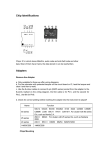
LART-CS08
Users Manual
Senior Design - Spring 2008
Lafayette College
4/06/2008
USER’S MANUAL
1.0 System Description
2.0 System Components
3.0 Getting Started
4.0 Safety Hazards
5.0 Demonstration Mode
6.0 Maintenance Mode
7.0 Troubleshooting
8.0 FAQ’s
1.0 System Overview:
The Lafayette Automated Rapid Transit Control System (LART-CS) is a versatile
and user-friendly system that controls the Lafayette Rapid Transit system. The Lafayette
Rapid Transit system is a model train system that controls multiple trains over the
Lafayette College campus and has stations at various locations. It offers a fully functional
user interface that allows both unskilled (Demonstration mode) and skilled users
(Maintenance Mode) of the system to operate the train system in their respective modes.
The user interface works with the hardware components of the control system in order to
communicate and dictate the operation of trains, and the switches on the tracks. It also
allows the user to receive feedback about the position and actual speed of a train using
sensors installed on the system. The remainder of this document outlines the major
components of the system, how to startup the system, the specific functions and
capabilities of each operation mode, system maintenance and calibration as well as a
listing of frequently asked questions.
2.0 System Components
Each station will be equipped with certain parts so that train operation will be
smooth and effective. Each station will be equipped with its own power supplies,
sensors, switches, rail segments and master terminal with software interface. There will
also be one central master station.
Power Supply – The power adapter for each station will detach off of a main power
supply running down the length of the tracks. Each station receives power and regulates
it to all equipment at that particular station including sensors, switches, and the physical
rails.
Sensors – Each station is equipped with sensors coming into and out of the station, letting
the user know where the train is at all times.
Switches – Switches are placed at every intersection of rail allowing the train to change
direction. Switches will be able to be controlled manually or automatically via the
sensors.
Rail Segments:
LART-CS08 – This is the software interface a user can use to control the operation of the
system. It will be operated in two modes by a single user. The modes are described in
more detail below.
Personal Computer – The LART-CS08 software operated on this PC.
3.0 Getting Started:
Parts List:
Part (Abbreviation)
• 1 surge protector (SP)
• 5 power adapters (PA)
• 4 extension cords (EC)
• 1 Personal Computer with necessary peripherals (PC)
• 1 Monitor (M)
• 5 station boxes (SB) with built in fan.
• 1 PCI Octopus card (O) with (1 to 8) serial cable connector.
• 5 serial communication cables (SC)
• 5 Grey 50 pin cable connectors (GC)
• 1 Entire rail system package (switches, sensors, rails, cabling, 3 trains – assumed
to be setup)
1.
2.
3.
4.
Check to make sure all parts are present.
Plug in surge protector to closest wall outlet
Plug in all extension cords in series to make a line down the entire rail system.
Mount each station box on the wall close to the 50 pin grey cable connector
already in place on the tracks.
5. Rotate the rotary switch (numbers 0-7) on each station board (in SB) and assign
each board with a unique number from zero to four.
6. Connect power cable from PC to surge protector.
7. Connect VGA cable attached to monitor to PC VGA slot.
8. Open up PC side panel and connect Octopus to an available PCI slot.
9. Connect 5 serial communication cables to 5 available ports on the Octopus’s (1-8)
output connector. Match male end of cable into female end on Octopus.
10. Connect the other ends of the serial communication cables to the serial slot on
each station board. Bring each connector into each station box through the
opening in the top.
11. Connect each of the 5 power adapters to the closest power extension cord outlets.
Connect the other end of the power adapter to power pin on the station boards.
12. Connect the female end of the 50 pin GC to its male terminal on each station
board. Bring each connector into each station box through the opening in the top.
13. System is ready to be turned on.
Basic Operations:
There are two basic operations. The first is demo or automatic mode. The second
mode of operation is maintenance or manual mode. Each mode is responsible for
operating 2 local trains along with 1 express train on the same set of rails.
Demo mode – The user is only responsible for observing the system and ensuring smooth
operation. In this mode the trains will operate on their own via a pre-programmed
schedule.
Maintenance mode – The user will be responsible for providing specific instructions for
the trains to follow. Users will need to provide inputs to control the power (speed) on
each rail segment and inputs to control each switch. A user will be able to see which
sensors are activated on the screen with a flashing light when a train moves over a sensor.
Information on how each mode will be used is described in sections 5.0 and 6.0.
4.0 Safety Harzards:
The major sources of safety hazards on this system are on the station boards and the rail
tracks. All components, on the station board and the rail segments/switches should not be
touched under any circumstances while the power is on. A red light on the surge protector
will indicate that the power is on.
5.0 Demonstration Mode
Start Up
To start Demonstration mode
1.
2.
3.
4.
5.
Turn on Computer
Select Train spotting program.
Wait for main page to come up.
Click on File > Operating Mode > Maintenance Mode
Wait for Demo mode page to show. Shown below.
Operation
This mode will operate and move the trains based on a pre-programmed schedule.
•
•
Clicking the GO (button labeled 2) will make the trains move on the tracks based
on the schedule of the program. This will operate 2 local trains with one express
train.
Clicking on the STOP button labeled 3 will make all trains on the system stop
where they are at their current location
•
•
•
Train locations will be able to be monitored by user incase of emergency.
o The tracks labeled 1 on the demo page will show the location of the trains
on the tracks. This picture will update with new locations via a sensor on
the track was tripped by a train passing over.
o The text box labeled 4 will give text updates of train locations providing
the train number, location (arrival at station), the direction the train is
traveling, next destination, and time of arrival at that particular location
via sensors on the track.
By clicking the File> Exit button labeled 5 the user can go back to the main page.
When the back button is clicked all train operation on the tracks is stopped and
will wait for another command before operation is started again.
By clicking File > Operating labeled 5 Mode the user can select if he/she wants to
switch to the maintenance mode. If you do switch the mode, everything on the
tracks will come to a complete stop.
1
5
2
3
4
6.0 Maintenance Mode
Start Up
To start Maintenance mode
1.
2.
3.
4.
5.
Turn on Computer
Select Train spotting program.
Wait for main page to come up.
Click on File > Operating Mode > Maintenance Mode
Wait for Maintenance mode page to show. Shown below.
Operation:
This mode will operate and move the trains based on specific inputs from the
user. It is assumed that the user for the maintenance mode will be well-versed technically.
Each rail pair and rail switch can be controlled individually, the train’s speed and
direction of switch being specified. The sensors provide feedback about the trains and
their information can be seen through the flashing radio buttons.
•
Select the station you’d like to control signals for from the drop down menu
(shown below). The layout of the rail pairs and switches for each station will
change depending on which station is selected.
•
Selecting a number from the drop down changes the speed of a train on the tracks.
There are 32 different speeds available including the stationary speed 0.
•
indicate the direction that a train will travel as well as
The arrow buttons
allowing the user to control the switch.
•
these will be activated once a train passes over it and
As far as the sensors go,
it will flash for the duration that the train is on the specific rail pairs.
•
At any point in time, the user may press the STOP button (shown below) to stop
all the trains moving on the tracks.
•
The user can click the “Help” button on the top left corner of the screen for
guidelines, tips and troubleshooting techniques.
By clicking the back button the user can go back to the main page. When the
back button is clicked all train operation on the tracks is stopped and will wait for
another command before operation is started again.
The user close the interface by clicking on File> Exit.
•
•
7.0 Troubleshooting:
Physical Problems
For any physical problems first read the getting started section and make sure that all the
connections between components are correct and the power switch on the surge protector
is lit.
Train does not move:
1. Check the LED power indicator in the station box closest to where the train is
stopped. If the LED is lit, proceed to step 2. If not, check power connections. If all
the connections are correct call Tech Support at 1-800-NADOVICH.
2. Restart the computer and start the LART-CS08 program.
3. If step2 does not work. Turn the main power off on the surge protector and turn
it back on again after 30secs.
Switches do not move:
1. Restart the LART-CS08 program.
2. Restart the computer and start the LART-CS08 program.
3. If step 1 does not work. Turn the main power off on the surge protector and
turn it back on again after 30secs.
Sensors do not provide feedback on screen:
1. Restart the LART-CS08 program.
2. Restart the computer and start the LART-CS08 program.
3. If step 1 does not work. Turn the main power off on the surge protector and
turn it back on again after 30secs.
Software Problems
Demonstration Mode
1. Restart the LART-CS08 program by exiting from the menu and double clicking
on the icon on the desktop again.
2. If step 1 did not work. Restart the computer and start the LART-CS08 program.
Maintenance Mode
1. Restart the LART-CS08 program by exiting from the menu and double clicking
on the icon on the desktop again.
2. If step 1 did not work. Restart the computer and start the LART-CS08 program.
8.0 FAQ
How do I turn on the system?
1. Turn on the main power switch by pressing the switch on the surge protector so
that the red-light turns on.
2. Turn on the Master PC by pressing the power button.
3. To open the operating program, double clicking on the LART-CS08 icon.
How do I turn off the system?
1. Close the LART-CS08 program by selecting File>Exit from the top toolbar.
2. Shutdown the Master PC by pressing the Start>Shutdown buttons.
3. Turn off the power switch on the surge protector so that the red-light is off.
How do I open the demonstration mode window?
To open the demonstration mode window.
1. Turn on the Master Station Computer
2. Select LART-CS08 icon on desktop
3. Wait for main page to come up.
4. Click on File > Operating mode > Demonstration mode.
5. Wait for Demo mode page to show.
How do I open the maintenance mode window?
To open the maintenance mode window.
1. Turn on the Master Station Computer
2. Select LART-CS08 icon on desktop
3. Wait for main page to come up.
4. Click on File > Operating mode > Maintenance mode.
5. Wait for maintenance mode page to show.
How do I stop all trains in-case of an emergency?
In case of an emergency there are three ways to stop all trains.
1. If the demonstration mode window is active then click the STOP button.
2. If the Maintenance mode window is active then click the STOP button.
3. Turn of the power switch on the surge protector.
How do I move the trains?
In demonstration mode, the user cannot control how the trains operate. There is a preprogrammed sequence of events that will happen every time the GO button is pressed.
In maintenance mode, the user is given a high level of freedom and flexibility. The train
speed on each individual set of rail pairs can be specified by selecting an appropriate
speed from the drop down menu. For more detail please read section 6.0.
How can I operate a rail switch?
In demonstration mode, the user cannot control how the switches operate. There is a preprogrammed sequence of events that will happen every time the GO button is pressed.
In maintenance mode, the user is given a high level of freedom and flexibility. The
direction of each individual switch can be specified by selecting an appropriate arrow
button on the window for a particular station. For more detail please read section 6.0.
What are the sensors for?
Sensors provide feedback to the control system so that the system knows where a train is
located at any point in time and how fast it is traveling. An active sensor is represented on
the maintenance mode window by a flashing radio button.