1
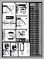
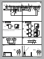
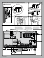
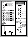
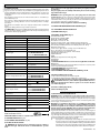
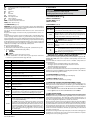
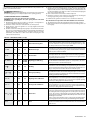
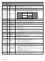
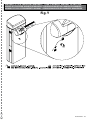
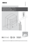
D811528 00100_03 10-11-09
027908
345073
ISTRUZIONI D’USO E DI INSTALLAZIONE
INSTALLATION AND USER’S MANUAL
INSTRUCTIONS D’UTILISATION ET D’INSTALLATION
INSTALLATIONS-UND GEBRAUCHSANLEITUNG
INSTRUCCIONES DE USO Y DE INSTALACION
GEBRUIKS- EN INSTALLATIEAANWIJZINGEN
AUTOMATISMO ELETTROMECCANICO PER BARRIERA VEICOLARE
ELECTROMECHANICAL CONTROL DEVICE FOR VEHICULAR BARRIERS
AUTOMATISME ELECTROMECANIQUE POUR BARRIERE POUR VÉHICULES
ELEKTROMECHANISCHER ANTRIEB FÜR FAHRZEUGSCHRANKEN
AUTOMATISMOS ELECTROMECANICOS PARA BARRÉRAS VEHICULAR
ELEKTROMECHANISCH AUTOMATISERINGSSYSTEEM VOOR SLAGBOOM
MICHELANGELO
MICHELANGELO
8
Attenzione! Leggere attentamente le “Avvertenze” all’interno! Caution! Read “Warnings” inside carefully! Attention! Veuillez lire attentivement les Avertissements qui se trouvent à l’intérieur!
Achtung! Bitte lesen Sie aufmerksam die „Hinweise“ im Inneren! ¡Atención¡ Leer atentamente las “Advertencias” en el interior! Let op! Lees de “Waarschuwingen” aan de binnenkant zorgvuldig!
D811528 00100_03
2 - MICHELANGELO
D811528 00100_03
A
S
3x
0,7
5
ITALIANO
INSTALLAZIONE VELOCE-QUICK INSTALLATION-INSTALLATION RAPIDE
SCHNELLINSTALLATION-INSTALACIÓN RÁPIDA - SNELLE INSTALLATIE
A
F
Ft
CS
CF
0,7
5
AL
RMM
4
Fr
M
ENGLISH
QR
2x
I
4
3x
T
B1
1
2
V
FRANÇAIS
Con scavo di fondazione:
With foundation plate embedded in ground:
Avec tranchée de fondation:
Mit Fundamentgraben:
Con excavación de cimentación:
Met uitgraving:
1,5
V
12
Con tiranti:
With anchor bolts:
Avec tirants:
Mit Ankerbolzen:
Con tirantes:
Met spankabels:
B2
DEUTSCH
35
3
1
2
ESPAÑOL
3
4
5
*
Ne sont pas fournis /
Nicht im lieferumfang /
No asignadas en el
equipamiento base/
Niet meegeleverd
MICHELANGELO - 3
NEDERLANDS
in dotazione /
* Non
Not supplied /
D
3
2
1
E
F
Per montaggio aste fare riferimento ai manuali ATT e ELL,
See manuals ATT and ELL for boom assembly,
Pour monter la barre consultez les manuels ATT et ELL,
Für die Montage der Stange auf die Handbücher ATT und ELL
Bezug nehmen,
Para montaje de los mástiles consultar los manuales ATT y ELL,
Voor montage stangen de ATT- en ELL-handboeken raadplegen.
Accessori opzionali, Optional extras, Accessoires facultatifs, Sonderzubehör, Accesorios Opcionales, Optionele Accessoires.
ATT 704/706
RMM
ACC MCL ELL
MCL RFL
MICHELANGELO
4 - MICHELANGELO
KIT MCL BAT
G
D811528 00100_03
Apertura e chiusura coperchio e portina, Opening and closing cover and door, Ouverture et fermeture du couvercle et portillon,
Öffnung und Schließung Abdeckung und kleine Tür, Apertura y cierre de la tapa y de la portezuela, Opening en sluiting deksel en klepje.
MCL 60 +
ATT706
MCL 60 +
ATT704 +
ATT502
MCL 60 +
ELL6
MCL 40 +
ELL6
MCL 40 +
ATT704
B
A
B
A
B
A
C
B
A
C
B
A
2,1
1,6
5,3
6
4,2
5,3
MIN L
MAX L
MIN L
MAX L
35 cm
5,1
MIN L
MAX L
6
5,2
MAX L
6
4,8
MIN L
3,8
6
MIN L
5,3
MIN L
MAX L
MAX L
3
3,8
MIN L
4
MAX L
MAX L
2,3
MIN L
L
3,6
2,9
4,1
3,6
4
3,2
4,7
4,2
2,3
1,8
2,7
3,3
3,8
MAX L
3
3,2
MIN L
2,6
MIN L
MAX L
MAX L
4
MIN L
2,5
3
2,1
3,4
MAX L
2,8
MIN L
3,7
2,9
4,2
3,7
4,1
3,2
4,8
4,3
2,3
1,8
2,8
2,3
3,3
3,1
2,1
1,6
2,6
2,1
3,1
2,8
4,2
3,3
4,7
4,2
4,1
2,8
5,2
4,5
4,9
3,9
5,5
4,9
2,7
2,1
3,2
2,6
3,8
3,6
2,4
1,9
2,9
2,4
3,4
3,2
4,2
3,3
4,8
4,3
4,2
2,9
5,3
4,5
4,9
4
5,6
5
2,8
2,2
3,3
2,7
3,9
3,6
2,5
2
2,9
2,4
3,5
3,3
4,4
3,5
4,9
4,4
4,5
3,1
5,5
4,7
5,3
4,3
5,9
5,4
2,9
2,3
3,4
2,8
4
3,8
2,5
2
3
2,5
3,6
3,4
L: Lunghezza utile asta.
L: Working boom length.
L: Longueur utile de la barre.
L: Nutzlänge der Schranke.
L: Longitud útil mástil.
L: Nuttige lengte slagboom.
3,8
3
4,3
3,8
4,2
3,3
4,9
4,4
2,4
1,9
2,9
2,4
3,4
3,2
2,2
1,7
2,6
2,2
3,1
2,9
4,5
3,6
5,1
4,5
4,5
3,1
5,7
4,9
5,3
4,2
6
5,3
3
2,3
3,5
2,9
4
3,9
2,6
2,1
3,1
2,6
3,7
3,5
4,7
3,7
5,3
4,7
5
3,4
5,9
5,1
5,5
4,4
6
5,4
3,1
2,4
3,7
3,1
2,8
2,2
3,3
2,7
3,9
3,6
4,6
3,6
5,2
4,6
4,9
3,4
5,9
5,2
5,5
4,3
6
5,4
3
2,3
3,6
3
2,7
2,1
3,2
2,6
3,8
3,5
5
3,9
5,6
5
5,1
3,6
6
5,3
5,5
4,5
6
5,6
3,4
2,6
4
3,3
2,9
2,3
3,5
2,8
4
3,9
3,8
3
4,3
3,8
4,4
3,6
5
4,5
2,5
2
2,9
2,5
3,5
3,3
2,3
1,8
2,7
2,3
3,2
3
3,9
3,1
4,4
3,9
4,4
3,7
5,1
4,6
2,5
2
3
2,5
3,5
3,3
2,3
1,8
2,7
2,3
3,2
3
(uniquement sur la barre)
(nur über der Schranke)
(sólo sobre el mástil)
(alleen boven de slagboom)
1
*(above
boom only)
4,8
3,8
5,4
4,8
5
3,5
6
5,2
5,5
4,4
6
5,5
3,2
2,5
3,8
3,1
2,8
2,2
3,3
2,7
3,9
3,7
4
3,2
4,5
4
4,5
3,8
5,2
4,7
2,6
2,1
3,1
2,6
3,7
3,4
2,4
1,9
2,8
2,4
3,3
3,1
4,6
3,7
5,2
4,6
5
4,2
5,8
5
5,5
4,5
6
5,4
3,2
2,5
3,7
3,1
2,8
2,2
3,3
2,8
3,9
3,6
(uniquement sous la barre)
(nur unter der Schranke)
(sólo debajo el mástil)
(alleen onder de slagboom)
4,5
3,6
5
4,5
4,6
3,4
5,6
4,8
5,3
4,4
6
5,4
3
2,4
3,6
3
4
3,9
2,7
2,1
3,2
2,7
3,8
3,5
2
*(below
boom only)
4,4
3,5
4,9
4,4
4,5
3,3
5,5
4,7
5,3
4,3
5,9
5,3
3
2,3
3,5
2,9
4
3,9
2,7
2,1
3,1
2,6
3,7
3,5
4,8
3,8
5,4
4,8
5,1
3,8
6
5,2
5,5
4,4
6
5,5
3,3
2,6
3,9
3,3
2,9
2,3
3,4
2,8
4
3,8
4,9
3,9
5,5
4,9
5,1
3,8
6
5,3
5,6
4,5
6
5,6
3,4
2,7
4
3,3
3
2,3
3,5
2,9
4
3,8
5,1
4
5,7
5,1
5,1
3,9
6
5,4
5,9
4,8
6
5,7
3,6
2,8
4
3,3
3,1
2,4
3,6
3
Accessori MICHELANGELO: lunghezza utile asta e bilanciamento. / MICHELANGELO Accessories: working length of boom and balancing. / Accessoires MICHELANGELO: longueur utile de la barre et équilibrage. /
MICHELANGELO Zubehör: Nutzlänge Schranke und Auswuchtung. / Accesorios MICHELANGELO: longitud útil mástil y balance. / Accessoires MICHELANGELO: nuttige lengte slagboom en balancering.
SB
+ SB
+ SB
+ SB
+ SB
+ SB + SB
+ PCA
+ PCA
+ PCA
+ PCA
+ PCA
+ PCA
+ PCA + PCA
+ PCA + PCA
+ PCA + PCA
+ PCA + PCA + PCA
MCL PCA (solo sopra l’asta)*1
+ PCA
+ PCA
+ PCA + PCA
MCL PCA (solo sotto l’asta)*2
KIT MCL LIGHT
+ LIGHT
+ LIGHT
+ LIGHT + LIGHT
+ LIGHT
+ LIGHT
+ LIGHT
GAM
+ GAM + GAM + GAM + GAM + GAM + GAM + GAM + GAM + GAM + GAM + GAM
BIR
+ BIR
+ BIR
+ BIR
+ BIR
+ BIR + BIR
D811528 00100_03
G1
MICHELANGELO - 5
D811528 00100_03
A
+ SB
+ PCA
+ PCA
G2
+ PCA
+ BIR
+ PCA + PCA
+ PCA + PCA
+ LIGHT
+ BIR
8
7,9
+ LIGHT
+ BIR
8
7,8
6
8
7,6
5,8
7,8
7,3
5,9
7
5,6
7,4
5,8
7,3
6,9
5,6
8
7,9
5,8
8
7,5
5,6
7,6
7,1
5,7
8
7,4
5,5
7,8
7,1
5,6
7,5
6,8
5,4
7,2
6,5
G3
MIN L
7,1
6,4
3
L
(above boom only)
(uniquement sur la barre)
(nur über der Schranke)
(sólo sobre el mástil)
(alleen boven de slagboom)
35 cm
MAX L
8
7,9
45°
5
L: Lunghezza utile asta.
L: Working boom length.
L: Longueur utile de la barre.
L: Nutzlänge der Schranke.
L: Longitud útil mástil.
L: Nuttige lengte slagboom.
(below boom only)
(uniquement sous la barre)
(nur unter der Schranke)
(sólo debajo el mástil)
(alleen onder de slagboom)
*2
MIN L
2
0°
+ 45 °
- 45 °
*1
MAX L
+ SB
+ SB
+ SB
+ SB
+ SB
+ PCA
+ PCA
+ PCA
+ PCA
+ PCA
+ PCA
+ PCA + PCA
+ PCA + PCA
+ PCA
+ PCA
+ LIGHT
+ LIGHT
+ LIGHT + LIGHT
+ LIGHT
+ GAM + GAM + GAM + GAM + GAM + GAM + GAM + GAM + GAM + GAM + GAM
+ BIR
+ BIR
+ BIR
Accessori MICHELANGELO 80: lunghezza utile asta e bilanciamento. / MICHELANGELO 80 Accessories: working length of boom and balancing. / Accessoires MICHELANGELO 80: longueur utile de la barre et équilibrage. /
MICHELANGELO 80 Zubehör: Nutzlänge Schranke und Auswuchtung. / Accesorios MICHELANGELO 80: longitud útil mástil y balance. / Accessoires MICHELANGELO 80: nuttige lengte slagboom en balancering.
MCL 80 +
ATT706
A
SB
MCL PCA (solo sopra l’asta)*1
MCL PCA (solo sotto l’asta)*2
KIT MCL LIGHT
GAM
BIR
MCL 80+
ATT704+
ATT504
+ 45 °
Bilanciamento Asta, Boom balancing, Equilibrage de la barre, Auswuchtung der Stange, Balance del mástil, Balancering stang.
1
4
90 °
45° OK
- 45 °
0°
6 - MICHELANGELO
Vsafe ~
24V ~
Vsafe ~
24V ~
H
Fig. H
Rif. 4, 5, 6
1
2
TEST PHOT=OFF
11
12
1
2
TX1
RX1
1-PHOT
1
2
3
11
12
15
5
18
4
LOGICA test fotocellule OFF, Photocell test LOGIC OFF, LOGIQUE essai
photocellules Désactivée, LOGIK Test Fotozellen OFF, LÓGICA prueba
fotocélulas OFF, LOGICA test fotocellen OFF.
TEST PHOT=ON
13
14
1
2
TX1
1-PHOT
5
3
6
5
21 22
11
12
15
19
18
4
13
14
13
14
JP9
4 SCA
11 12
1
2
3
RX1
1
2
TX1
RX1
2-PHOT
24 V~
D811528 00100_03
Collegamenti morsettiera, Terminal board wiring, Branchements sur le bornier, Anschlüsse Klemmleiste,
Conexiones tablero de bornes, Aansluitingen aansluitkast.
1
2
TX2
RX2
1
2
3
4
5
11
12
1
2
3
4
5
11
12
15
18
19
15
Uscita Allarme, Alarm Output, Sortie Alarmes
Alarmausgang, Salida Para Alarma, Uitgang Alarm
JP9
19 20 21 22
Connessione A Sistema Gestione Parcheggi Parky, Connection To Parky Car-park Management System, Connexion Au Système De Gestion Des
Parkings Parky, Anschluss An Das Parkplatzbewirtschaftungssystem Parky, Conexion Al Sistema De Gestion De Aparcamientos Parky, Erbinding
Met Beheersysteem Parky-parkeerplaatsen
MICHELANGELO - 7
1
I
2
3
Connettore programmatore palmare,
Palmtop programmer connector,
Connecteur programmateur de poche,
Steckverbinder Palmtop-Programmierer,
Conector del programador de bolsillo,
Connector programmeerbare palmtop.
Vsafe ~
24V ~
Vsafe ~
Display + tasti programmazione,
Display plus programming keys,
Afficheur et touches de programmation,
Display und Programmierungstasten,
Pantalla mas botones de programacion,
Display meerdere toetsen programmeur.
24V ~
+ -
4
Fig. H
Rif. 4, 5, 6
8 - MICHELANGELO
Connettore scheda opzionale,
SCS1 optional board connector,
Connecteur carte facultative,
Steckverbinder Zusatzkarte,
Conector de la tarjeta opcional,
Connector optionele kaart.
L
D811528 00100_03
Cablaggio Trasformatore, Transformer wiring, Câblage du transformateur,
Verkabelung Transformator, Cableado Transformador, Bekabeling Transformator.
D811528 00100_03
REGOLAZIONI PRELIMINARI, PRELIMINARY ADJUSTMENTS,
RÉGLAGES PRÉALABLES, VORLÄUFIGE EINSTELLUNGEN,
REGULACIONES PRELIMINARES, VOORLOPIGE AFSTELLINGEN.
+
-
OK
x2
M
Modificare i valori seguenti fino a raggiungere
il movimento dell’asta desiderato,
Edit the following values until you are happy
with boom movement,
Modifiez les valeurs suivantes jusqu'à ce que la
barre se déplace de la façon voulue,
Die folgenden Werte verändern, bis die
gewünschte Bewegung der Stange erzielt wird,
Modificar los siguientes valores hasta lograr el
movimiento deseado del mástil,
Onderstaande waarden wijzigen tot de
beweging van de gewenste stang bereikt wordt.
MEMORIZZAZIONE RADIOCOMANDO
MEMORIZING REMOTE CONTROLS
MÉMORISATION DE LA RADIOCOMMANDE
ABSPEICHERUNG DER FERNBEDIENUNG
MEMORIZACIÓN DEL RADIOMANDO
MEMORISEREN AFSTANDSBEDIENING
O
+
8888
OK
PArAM
OK
OK
Coppia-TOrque
couple-Drehmom-Par
OK
[085]
default
accel.-Beschl.-acel.
OK
[075]
default
P1 +
P2 -
x2
PRG ok
PArAM
P1 +
P2 -
PRG ok
logic
Vel.Ap.-Op.speed
vit. ouv.-off. ges.
OK
[099 - 050]
default
P1 +
P2 -
PRG ok
OK
MICHELANGELO 60: [099]
MICHELANGELO 80: [050]
freno - brake
frein - bremse
OK
cal. ap. - open. calib.
cal. ouv. - off. kal.
cal.ap.
OK
cal. ch. - clos. calib.
cal. ferm. - sch. kal.
cal. cie.
OK
[50]
default
[082.0]
default
[021.0]
default
P1 +
P2 -
PRG ok
P1 +
P2 -
PRG ok
P1 +
P2 -
PRG ok
radio
AGG.START- adjouter
start-zufueg.startanad.start
OK
tasto nascostohidden buttontouche cacheeverst.taste
rilascia-release
relache-loslassen
suelte
fine-end-fin
tasto desideratodesider button touche desireegevue tastetecla deseada
N
ok 01 . . .
x2
end
MICHELANGELO - 9
Assicurarsi che la molla non sia in tensione, e l’asta non sia montata.
Make sure the spring is not under tension and the boom is not fitted.
Vérifiez si le ressort n'est pas en tension et si la tige n'est pas montée.
Sicherstellen, dass die Feder nicht gespannt und die Stange nicht montiertist.
Asegurarse de que el muelle no esté tensado y de que el mástil no esté
montado.
Controleren of de veer niet onder spanning staat, en de stang niet
gemonteerd is.
Smontare il gruppo molla.
Remove the spring assembly.
Démonter le groupe ressort.
Die Feder-Baugruppe ausbauen.
Desmontar el grupo muelle.
De groep veer demonteren.
2
1
3
19
4
10 - MICHELANGELO
19
AA
D811528 00100_03
Montaggio Asta Destra, Assembly of right boom, Montage de la barre droite,
Rechte Montage der Stange, Montaje mástil derecho, Montage rechterstang.
D811528 00100_03
Rimontare il gruppo molla a destra, Refit the right-hand spring assembly,
Remontez le groupe ressort à droite, Die Baugruppe neu montieren, Feder rechts,
Volver a montar el grupo muelle a la derecha, De veergroep opnieuw rechts monteren.
AB
6
5
7
8
9
MICHELANGELO - 11
Assicurarsi che la molla non sia in tensione, e l’asta non sia montata.
Make sure the spring is not under tension and the boom is not fitted.
Vérifiez si le ressort n'est pas en tension et si la tige n'est pas montée.
Sicherstellen, dass die Feder nicht gespannt und die Stange nicht montiertist.
Asegurarse de que el muelle no esté tensado y de que el mástil no esté montado.
Controleren of de veer niet onder spanning staat, en de stang niet gemonteerd is.
1
2
2 mm
2 mm
3
19
12 - MICHELANGELO
D811528 00100_03
AC
D811528 00100_03
AD
4
19
5
6
13
30 mm
MICHELANGELO - 13
2
1
3
4
5
14 - MICHELANGELO
AE
D811528 00100_03
Montaggio Fotocellule CELLULA 130, Fitting Photocell 130, Montage de CELLULA 130,
Montage CELLULA 130, Montaje CELLULA 130, Montage CELLULA 130.
D811528 00100_03
Montaggio Fotocellule CELLULA 130, Fitting Photocell 130, Montage de CELLULA 130,
Montage CELLULA 130, Montaje CELLULA 130, Montage CELLULA 130.
6
7A
Fori verticali CELLULA 130,
PHOTOCELL 130 vertical holes,
Trous verticaux CELLULA 130,
Vertikale Bohrungen CELLULA 130,
Orificios verticales CELLULA 130,
Vertikale Bohrungen CELLULA 130.
AF
7B
Fori orizzontali cellula 130,
PHOTOCELL 130 horizontal holes,
Trous horizontaux CELLULA 130,
Horizontale Bohrungen CELLULA 130,
Orificios horizontales CELLULA 130,
Horizontale openingen CELLULA 130.
8
Fare riferimento al manuale Cellula 130,
Refer to PHOTOCELL 130 manual,
Consultez le Manuel CELLULA 130,
Auf das Handbuch CELLULA 130 Bezug nehmen,
Consultar el manual CELLULA 130,
Het handboek CELLULA 130 raadplegen.
Per montaggio colonnine fare riferimento al manuale MCL 130,
Refer to MCL 130 manual for assembly of stations,
Pour monter les colonnes consultez le manuel MCL 130,
Für die Montage der Säulen auf das Handbuch MCL 130 Bezug nehmen,
Para montar las columnas consultar el manual MCL 130,
Voor montage kolommen het handboek MCL 130 raadplegen.
ATTENZIONE! Solo per MCL 80 asta con apertura a destra: installare il
gruppo colonnina prima di spostare il gruppo molla.
WARNING! For MCL 80 boom with opening on right only: install station
unit before moving spring assembly.
ATTENTION! Uniquement pour MCL 80 barre avec ouverture à droite:
montez le groupe colonne avant de déplacer le groupe ressort.
ACHTUNG! Nur für MCL 80 Stange mit Öffnung rechts: Die Baugruppe
Säule installieren, bevor die Baugruppe Feder versetzt wird.
¡ATENCIÓN! Sólo para MCL 80 mástil con apertura a la derecha: instalar
el grupo columna antes de desplazar el grupo muelle.
OPGELET! Alleen voor MCL 80 stang met opening rechts: de kolommengroep installeren, alvorens de veergroep te verplaatsen.
MICHELANGELO - 15
2
1
4
3
A
*
B
5
6
in dotazione /
* Non
Not supplied / Ne sont pas fournis /
Nicht im lieferumfang /
No asignadas en el equipamiento base /
Niet meegeleverd
4
8
16 - MICHELANGELO
AG
D811528 00100_03
Montaggio RMM, Fitting RMM, Montage de RMM, Montage RMM, Montaje RMM, Montage RMM.
D811528 00100_03
ACCESS TO MENUS
Press the OK key
Scroll up
Scroll down
Control unit software version
N. total manoeuvres (in tens)
Cancel/return to main menu
Confirm/Switch on display
N. manoeuvres since latest maintenance (in tens)
N. radio control devices memorised
See PARAMETERS MENU
param. 1
end
ENGLISH
param. 2
param. . . .
logic
logic. 1
See LOGIC MENU
logic. 2
end
logic. . . .
radio
add. start
hidden button
release
01 t1
desired button
ok 01
See RADIO MENU
read
end
PRG.
erase 64
+/COD RX
1A9C
OK
22FD
OK
01
OK
v
language
ITA
OK
- +
FRA
OK
- +
end
DEU
OK
- +
ENG
OK
- +
esp
default
end
PRG
OK
Logic
Description
STOP
BAR
AmP
Enc
PHOT
STOP input activation
Fltf
time
tTca
CLOS
OPEN
STRT
Swo
Suc
REfo
refc
th
FAULT input activation for checked photocells
ER0x
ER1x
ER2X
ER4x
EREF
35.40
EDGE input activated (obstacle alarm)
ampere-stop triggering (obstacle alarm)
encoder stopped detected (obstacle alarm)
PHOT input activation
TIMER input activation
waiting time for automatic closing on TIMER release
CLOSE input activation
OPEN input activation
STARTinput activation
barrier in opening position
barrier in closing position
reference input on opening activated
reference input on closing activated
overload signal indication (the system completes the manoeuvre in progress
and does not allow new ones until the signal indication has been eliminated).
check on safety devices failed
check on motor control failed
power supply cables for motor or encoder signal reversed
overload error (the system remains under protection lock until the error has
been corrected).
error due to position references both active.
Set torque threshold %
Maximum motor torque %
MICHELANGELO - 23
WARNING! Important safety instructions. Carefully read and comply with
the Warnings booklet and Instruction booklet that come with the product as
incorrect installation can cause injury to people and animals and damage to
property. They contain important information regarding safety, installation,
use and maintenance. Keep hold of instructions so that you can attach them
to the technical file and keep them handy for future reference.
1) GENERAL SAFETY
WARNING! An incorrect installation or improper use of the product can
cause damage to persons, animals or things.
• The “Warnings” leaflet and “Instruction booklet” supplied with this
product should be read carefully as they provide important information
about safety, installation, use and maintenance.
• Scrap packing materials (plastic, cardboard, polystyrene etc) according
to the provisions set out by current standards. Keep nylon or polystyrene
bags out of children’s reach.
• Keep the instructions together with the technical brochure for future
reference.
• This product was exclusively designed and manufactured for the use
specified in the present documentation. Any other use not specified in
this documentation could damage the product and be dangerous.
• The Company declines all responsibility for any consequences resulting from
improper use of the product, or use which is different from that expected
and specified in the present documentation.
• Do not install the product in explosive atmosphere.
• The units making up the machine and its installation must meet the requirements of the following European Directives: 2004/108/EEC, 2006/95/EEC,
98/37/EEC, 99/05/EEC (and later amendments). For all countries outside
the EEC, it is advisable to comply with the above-mentioned standards,
in addition to any national standards in force, to achieve a good level of
safety.
• The Company declines all responsibility for any consequences resulting
from failure to observe Good Technical Practice when constructing closing structures (door, gates etc.), as well as from any deformation which
might occur during use.
• The installation must comply with the provisions set out by the following
European Directives: 2004/108/EEC, 2006/95/EEC, 98/37/EEC, 99/05/EEC
and subsequent amendments.
• Disconnect the electrical power supply before carrying out any work on
the installation. Also disconnect any buffer batteries, if fitted.
• Fit an omnipolar or magnetothermal switch on the mains power supply,
having a contact opening distance equal to or greater than 3,5 mm.
• Check that a differential switch with a 0.03A threshold is fitted just before
the power supply mains.
• Check that earthing is carried out correctly: connect all metal parts for
closure (doors, gates etc.) and all system components provided with an
earth terminal.
• Fit all the safety devices (photocells, electric edges etc.) which are needed
to protect the area from any danger caused by squashing, conveying and
shearing, according to and in compliance with the applicable directives
and technical standards.
• Position at least one luminous signal indication device (blinker) where it
can be easily seen, and fix a Warning sign to the structure.
• The Company declines all responsibility with respect to the automation safety
and correct operation when other manufacturer’s components are used.
• Only use original parts for any maintenance or repair operation.
• Do not modify the automation components, unless explicitly authorised
by the Company.
• Instruct the product user about the control systems provided and the
manual opening operation in case of emergency.
• Do not allow persons or children to remain in the automation operation
area.
• Keep radio control or other control devices out of children’s reach, in
order to avoid unintentional automation activation.
• The user must avoid any attempt to carry out work or repair on the automation system, and always request the assistance of qualified personnel.
• Anything which is not expressly provided for in the present instructions,
is not allowed.
• Installation must be carried out using the safety devices and controls
prescribed by the EN 12978 Standard.
WARNINGS
Correct controller operation is only ensured when the data contained in the
present manual are observed. The Company is not to be held responsible
for any damage resulting from failure to observe the installation standards
and the instructions contained in the present manual.
The descriptions and illustrations contained in the present manual are not
binding. The Company reserves the right to make any alterations deemed
appropriate for the technical, manufacturing and commercial improvement
of the product, while leaving the essential product features unchanged, at
any time and without undertaking to update the present publication.
24 - MICHELANGELO
USE OF AUTOMATION
As automation can be remotely controlled and therefore not within sight, it is
essential to frequently check that all safety devices are perfectly efficient.
WARNING! In case of any malfunction in the safety devices, take imme-diate
action and require the assistance of a specialised technician.
It is recommended to keep children at a safe distance from the automation
field of action.
CONTROL
The automation system is used to obtain motorised access control. There are
different types of control (manual, remote, magnetic badge, mass detector
-Fig. AH- etc.) depending on the installation requirements and characteristics.
For the various control systems, see the relevant instructions.
MAINTENANCE
WARNING: before opening the door, the spring must be unloaded
(vertical boom). WARNING: Before carrying out any maintenance to the
installation, disconnect the mains power supply. The following points need
checking and maintenance:
- Photocell optics. Clean occasionally.
- Electric edge. Carry out a periodical manual check to ensure that the edge
stops the bar in case of obstacles.
- Dismantle the gearmotor and replace the lubricating grease every two
years.
- When any operational malfunction is found, and not resolved, disconnect the mains power supply and request the assistance of a specialised
technician (installer). When the operator is out of order, activate the
emergency release (see Fig. Y), if necessary, so as to release the manual
boom opening and closing operations.
SCRAPPING
Materials must be disposed of in conformity with the current regulations.
In case of scrapping, the automation devices do not entail any particular
risks or danger. In case of recovered materials, these should be sorted out
by type (electrical components, copper, aluminium, plastic etc.).
DISMANTLING
WARNING: before opening the door, the spring must be unloaded (vertical boom). When the automation system is disassembled to be reassembled
on another site, proceed as follows:
- Disconnect the power supply and the entire electrical installation.
- Remove the actuator from its fixing base.
- Disassemble all the installation components.
- In the case where some of the components cannot be removed or are
damaged, they must be replaced.
D811528 00100_03
INSTALLATION MANUAL
D811528 00100_03
INSTALLATION MANUAL
2) GENERAL OUTLINE
Compact electromechanical barrier suitable for limiting private areas, parkings, access areas for vehicles only. Available for passageways from 4 to 8
metres. Adjustable electronic limit switches, they guarantee correct boom
stopping position. In case of intensive use, a thermal sensor activates the
cooling fan.
The emergency release device for manual manoeuvre is controlled by a
personalised key lock.
The actuator is always supplied for left-hand side fitting. However, when
necessary, the opening direction can be reversed by means of simple
operations.
The BM mod. foundation base (on request) makes barrier installation
easier.
Appropriate fittings make it easy to install accessories.
The LIBRA C MV control panel is supplied by the manufacturer with standard
setting. Any change must be set by means of the incorporated display or by
means of the universal programmer.
3) TECHNICAL SPECIFICATIONS
Power supply:
230V±10% 50Hz(*)
Power absorbed:
300W
Absorption (with accessories):
1A
Internal lubrication:
permanent grease
Max torque:
600 Nm
Opening time:
6s (5-6m), 8s (8m)
Boom length:
4m (MICHELANGELO 40)
5-6m (MICHELANGELO 60)
da 6m a 8m (MICHELANGELO 80)
Impact reaction:
encoder
Manual mechanical release:
customised key
Type of boom:
rectangular/round
Limit devices:
electrical incorporated and electronically adjustable
Maximum no. manoeuvres in 24h: continuous operation
Working temperature:
from -20°C to +55°C
Degree of protection:
IP 24
Operator weight (without boom):
55 Kg (MICHELANGELO 40)
58 Kg (MICHELANGELO 60)
68 Kg (MICHELANGELO 80)
Dimensions:
see fig. A
Mains/low voltage insulation:
> 2MOhm 500V
Dielectric strength:
mains/low voltage 3750V~ for 1
minute
Motor output current:
20A max (MICHELANGELO 40)
25A max (MICHELANGELO 60)
30A max (MICHELANGELO 80)
Cooling intervention
temperature:
80°C
Supply to accessories:
24V~ (180 mA max absorption)
Barrie-open warning light:
24V~ 3W max
Blinker:
24V~ 25W max
Fuses:
see figure I-L
N° of combinations:
4 billion
Max. n° of remotes that
can be memorized:
63
(*)= special power supply voltages on request.
Usable transmitter versions:
All ROLLING CODE transmitters compatible with
4.1) FOUNDATION PLATE (Fig. B1).
4.2) FASTENING ANCHOR BOLTS (Fig. B2).
5) FITTING OF THE ACTUATOR
WARNING! The barrier must be exclusively used for vehicles to
drive through. Pedestrians must not walk within the operator
manoeuvring area. An appropriate pedestrian passageway must be
provided for.
The passageway must be suitably indicated by means of the warning
signs illustrated in Fig.A.
WARNING: before opening the door, the spring must be unloaded
(vertical boom). The door of the box must be facing towards the inside
of the property. When you stand in the middle of the passageway, facing
outwards, if the box is on your left, the barrier is left-hand fitted, if the box
is on your right, the barrier is right-hand fitted.
The actuator is always supplied for left-hand side fitting.
5.1) COVER AND DOOR OPENING AND CLOSING (Fig. D).
5.2) POSITIONING OF ENCLOSURE FIG.E
5.3) BOOM FIXING (Fig. F).
6) OPTIONAL ACCESSORIES (Fig. G)
Foundation Base - BM
Boom light kit - KIT MCL LIGHT
Blinker kit - KIT MCL LAMPO
Moveable boom rest rod - GA
Fixed boom support fork - FAF (compulsory with 7-8m boom).
Cellula130 post fixing kit - KIT MCL 130 (only when GA and SB are absent)
Skirt already assembled to the boom - SB (only for boom - ELL 6)
BIR passive safety edge
Lower and/or upper boom covering contour - MCL PCA 6/8
ELL 6 - ATT 704/706 - ATT 504/502 Booms.
ACC MCL ATT KIT (for ATT 704/706 - ATT 504/502)
ACC MCL ELL KIT (for ELL 6)
SCHEDA MCL KIT
LOOP
RMM (metal object detector 24V) (Fig. AG)
KIT MCL BAT,
KIT MCL RFL
6.1) MICHELANGELO 40-60 accessories: boom length limits and balancing (Fig. G1).
For further information about the installation and use of accessories, refer
to the respective instruction manuals.
6.2) MICHELANGELO 80 accessories: Fig.G2.
6.3) BAR BALANCING (Fig. G3).
6.4) ATTACHMENT AND TENSIONING OF SPRING fig. AC-AD
7) Right-hand fitting (Fig. AA, AB)
- Carry out bar balancing as described in Fig. G3.
- Set the Direction Reversal logic to ON in the control panel.
Warning: the Direction Reversal logic must be configured to OFF for
left-hand fitted barriers, and to ON for right-hand fitted barriers.
Otherwise, the limit devices will not operate or an encoder direction
error will be displayed.
8) Cellula 130 fitting (Fig. AE-AF)
9) MCL 130 fitting (Fig. AF)
----------------------------------------------------------
10) ELECTRICAL INSTALLATION SET-UP
WARNING: before opening the door, the spring must be unloaded (vertical boom). Set up the electrical installation (fig. A) with reference to the
current regulations for electrical installations. Keep the mains power supply
con-nections definitely separate from the service connections (photocells,
electric edges, control devices etc.).
Warning! For connection to the mains, use a multipolar cable having
minimum 3x1.5mm2 cross section and complying with the previously
mentioned regulations (for example, if the cable is not protected, it
must be at least equal to H07 RN-F, whereas if it is protected it must be
at least equal to H07 VV-F with a 3x1.5 sq mm2 cross section).
Fig. A shows the number of connections and section for a 100m length of
power supply cables; for greater lengths, calculate the section for the true
automation load. When the auxiliary connections exceed 50 metre lengths
or go through critical disturbance areas, it is recommended to decouple the
control and safety devices by means of suitable relays.
The main automation components are (fig. A):
I) Type-approved adequately rated omnipolar circuit-breaker with
at least 3,5 mm contact opening, provided with protection against
overloads and short circuits, suitable for cutting out automation from
the mains. Place, if not al ready installed, a type-approved differential
switch with a 0.03A threshold just before the automation system.
MICHELANGELO - 25
QR) Control panel and incorporated receiver.
S) Key selector.
AL) Blinker
M) Actuators.
A) Bar.
F) Rest fork.
CS) Electric edge.
Ft,Fr) Pair of photocells.
CF) Photocell post.
T) 1-2-4 channel transmitter.
RMM) Inductive metal mass detector.
LOOP) Mass detector loops.
11) CONNECTION (FIg. H-I)
WARNING: The electrical connections must be carried out workmanlike by
qualified experienced personnel, in conformity with all the current standards
and with the use of appropriate materials.
Lay out the electrical installation with reference to the current electrical
standards.
Keep the mains supply connections clearly separated from the service connections.
In the initial section of the electrical installation, fit a circuit breaker with a
contact opening distance equal to or greater than 3,5 mm, provided with
magnetothermal protection and a differential switch having adequate capacity for the appliance consumption. For the wiring, only use cables conforming
to the harmonised or national standards, having a cross section corresponding to the initial protection, the appliance consumption and the installation
conditions, for example a 3x1.5 sq mm (H 05 VV-F) cable.
Proceed as explained below:
1. Remove the transformer cover.
2. Unscrew the screw which locks the cap (Fig. I Rif. 1) and take the cap out.
3. Fix the cables to the terminal bar (Fig. I Rif. 2)
L PHASE
N NEUTRAL
EARTH
4. To close the cap, reverse the actions in step 2.
5. Refit the transformer cover and secure in place by means of the slots
located on top of the transformer (Fig. I Rif. 3-4).
TERMINAL
1-2
3-4
6-7
15-5
15-8
9-10
11-12
13-14
15-16
15-17
15-18
19
15-20
21-22
23-2425-26
15-27
15-28
JP8-JP6
DESCRIPTION
Control for cooling fan
Not used
Motor connections
Motor connections, closing reference
Motor connections, opening reference
Blinker connection (24 V~, 25W)
24 V~ 180mA max output – power supply for photocells or
other devices (11+,12-).
24 V~ 180mA max output – power supply for photocell
transmitters with check (Vsafe 13+, 14-).
START button (N.O.)
STOP button (N.C.). If not used, leave the jumper bridged
Photocell input (N.C.). If not used, leave the jumper bridged
Photocell FAULT input (N.O.) for photocells provided with
N.O. check contact
Safety edge input (N.C.). If not used, leave the jumper
bridged
Barrier-open warning light output (N.O. contact, 24V~/ 3W max)
or, in alternative, alarm output (see configuration paragraph)
and Connection To Parky Car-Park Management System
Encoder inputs
Open button (OPEN N.O.). If the TIMER logic on OPEN is enabled
and the input remains engaged for over 3 sec., it commutes
to clock input (TIMER N.O.).
The TIMER input opens and keeps the barrier open when
engaged; on disengagement, after waiting for the time set
in the Automatic Closing Time parameter, it starts the closing
movement (regardless of the TCA Logic status). If the command is interrupted by the STOP button being pressed or
by the safety devices being triggered, it can be reset using
the START input
Close button (CLOSE N.O.)
Board power supply (24V~) (JP8 +,JP6-)
26 - MICHELANGELO
12) ADJUSTMENTS
RECOMMENDED ADJUSTMENT SEQUENCE:
Adjusting the limit switches (See reference section) FIG.M
Programming remote controls (Fig. O)
Setting of parameters/logic, where necessary
13) PARAMETERS MENU (para )
(TABLE “A” PARAMETERS)
14) LOGIC MENU (logic)
(TABLE “B” LOGIC)
15) RADIO MENU (RADIO)
Logic
add start
Description
Add Start Key
associates the desired key with the Start command
read
Read
Checks a key of a receiver and, if memorized, returns the
number of the receiver in the memory location (from 01
to 64) and number of the key (T1-T2-T3 or T4).
erase 64
Erase List
WARNING! Erases all memorized remote controls
from the receiver’s memory.
cod RX
Read receiver code
Displays receiver code required for cloning remote
controls.
v
ON = Enables remote programming of cards via a previously memorizedW LINK transmitter. It remains enabled for 3 minutes
from the time the W LINK remote control is last pressed.
OFF=W LINK programming disabled.
- IMPORTANT NOTE: THE FIRST TRANSMITTER MEMORIZED MUST BE
IDENTIFIED BY ATTACHING THE KEY LABEL (MASTER).
In the event of manual programming, the first transmitter assigns the RECEIVER’S KEY CODE: this code is required to subsequently clone the radio
transmitters.
The Clonix built-in on-board receiver also has a number of important advanced features:
• Cloning of master transmitter (rolling code or fixed code)
• Cloning to replace transmitters already entered in receiver
• Transmitter database management
• Receiver community management
To use these advanced features, refer to the universal handheld programmer’s
instructions and to the CLONIX Programming Guide, which come with the
universal handheld programmer device.
16) LANGUAGE MENU (language)
Used to set the programmer’s language on the display.
17) DEFAULT MENU (default)
Restores the controller’s default factory settings.
18) CONNECTION TO PARKY CAR-PARK MANAGEMENT SYSTEM
The board can be configured in order to make an output available for controlling the barrier status. When the SCA Alarm logic is disabled (OFF) and
the Alarm Time parameter is set to 0 s, the SCA contact (21-22) is configured
as follows (Fig. H Rif. 6):
- contact closed between terminals 21-22 with the barrier lowered
- contact open between terminals 21-22 with the barrier lifted
19) LIMIT SWITCH SETTING
WARNING: before opening the door, the spring must be unloaded (vertical
boom). The barrier is provided with programmable electronic limit switches
and mechanical stop devices. There must be a rotation margin (about 1°) on
closing and opening between the electrical limit switches and mechanical
stop devices (Fig. N). The adjustment is carried out as follows:
The end-of-stroke opening and closing positions must be set by modifying
the parameters of the control panel for Opening value Calibration and Closing value Calibration: if the value is increased, the end-of-stroke positions
move towards the opening direction. The extent of the movement depends
on the effective boom length: in the case of a 6-m boom, a unit change (1.0)
entails a movement of about 4,4 cm which, proportionally, becomes about
5,8 cm for an 8-m boom.
The effective closing value also depends, in part, on the manoeuvring speed.
It is therefore convenient to proceed to end-of-stroke calibration only after
having set the other opening parameters.
D811528 00100_03
INSTALLATION MANUAL
D811528 00100_03
INSTALLATION MANUAL
To evaluate correctly the values set, you are advised to carry out a few complete consecutive manoeuvres.
20) EMERGENCY RELEASE (Fig. Y)
WARNING! When an actuator without bar needs to be released, ensure that
the balancing spring is not compressed (bar in the opening position).
21) MALFUNCTION: CAUSES and REMEDIES
21.1) The bar does not open. The motor does not turn.
WARNING: before opening the door, the spring must be unloaded
(vertical boom).
1) Check that the photocells are not dirty, or engaged, or not aligned. Proceed accordingly. Check the electric edge.
2) Check the correct connection of the drive motor and capacitor.
3) Check that the electronic appliance is correctly supplied. Check the
integrity of the fuses.
4) Use the control unit self-diagnosis (Fig. I-O), to check whether the functions are correct. Identify any possible cause for the fault. If self-diagnosis
indicates that a start command persists, check that there are no radio
transmitters, start buttons or other control devices keeping the start
contact activated (closed).
4) Use the control unit self-diagnosis (see “Acces to Menus”), to check whether
the functions are correct. Identify any possible cause for the fault. If selfdiagnosis indicates that a start command persists, check that there are
no radio transmitters, start buttons or other control devices keeping the
start contact activated (closed).
5) If the control unit does not work, it must be replaced.
6) Check the activation of the reference microswitches by checking the
messages appearing on the control panel display.
7) Lubrificate the guide-ressort tirants in case of rumors or vibrations.
21.2) The bar does not open. The motor turns but there is no movement.
1) The manual release was left engaged. Reset the motorised operation.
2) If the release is in the motorised operation position, check the gearmo- tor
for integrity.
TABLE “A” - PARAMETERS MENU - (PARA )
Logic
tca
min.
max.
default
1
180
10
Definition
Description
Automatic Closing Time
Automatic Closing Time [s]
Set the numerical value of the automatic closing time from 1 to 180
seconds. Automatic closing can be deactivated by the TCA Logic, but
it is always carried out on releasing the TIMER.
torque
60
99
85
Maximum torque
Maximum torque [%]
Set from 60% to 99% the maximum torque that activation must be able
to provide before generating an obstacle alarm. With the maximum
value set, the control is disabled.
accel.
1
99
75
Acceleration
Acceleration [%]
Special parameter 14 on second-generation universal programmers.
Set a value from 1% to 99% for the acceleration to be applied at the
beginning of each movement.
Op. speed
1
99
99 M60
50 M80
Opening speed/Closing
Opening speed/Closing [%]
Set the numerical value of the speed: 1% corresponds to the slowdown speed, 99% to the maximum speed.
bra e
0
85
50
Braking
Braking [%]
Set from 0% to 85% the braking to be applied during the slow-down
phase. The initial slow-down value is automatically calculated according to this parameter and the effective movement speed.
e er.bra e
75
99
75
Emergency braking
Emergency braking [%]
Set a value from 75% to 99% for the braking intensity in case of reversing
movement or emergency braking: any values lower than those set in the
“braking” parameter will be ignored.
cal. ap.
0
100
82
Opening value calibration
Opening value calibration [%]
Special parameter 1 on second-generation universal programmers.
Set the reference value from 0,0 to 100,0 for the required opening
position (see Paragraph Limit Switch Setting).
Closing value calibration
Closing value calibration [%]
Special parameter 2 on second-generation universal programmers.
Set the reference value from 0,0 to 100,0 for the required closing
position (see Paragraph Limit Switch Setting).
cal. ch.
0
100
21
alar . ti e
10
240
30
Alarm time
Alarm time [%]
In the case of obstacle detection or photocell engagement for a period
exceeding the time set (ranging from 10 s to 240 s), the SCA contact
closes. The contact is subsequently opened by the STOP command
or by triggering of the closing limit switch. Only active when the SCA
Alarm logic is set to OFF.
If set to 0 s, the SCA contact becomes a connection to the Parky system
(see Paragraph Connection To Parky Car-Park Management System).
Zone
0
127
0
Zone
Zone [ ]
Set the zone number between a minimum value of 0 and a maximum
value of 127.
MICHELANGELO - 27
D811528 00100_03
INSTALLATION MANUAL
TABLE “B” - LOGIC MENU - (logic)
Logic
default Definition
Description
tca
ON
Automatic
closing time
ON: Activates automatic closing
OFF: Excludes automatic closing
Note: automatic closing on TIMER release cannot be deactivated.
2 step
OFF
2-step logic
ON: Enables the 2-step logic (prevails over the “3-step logic”).
OFF: Disables the 2-step logic, activating the 4-step logic if the “3-step logic” is OFF.
ON: Enables the 3-step logic (if the “2-step logic” is OFF).
OFF: Disables the 3-step logic, activating the 4-step logic if the “2-step logic” is OFF.
Response to the START impulse
Barrier
3 step
ON
3-step logic
closed
on closing
open
on opening
after stop
2 steps
3 steps
opens
opens
closes
opens
4 steps
opens
stop
closes
closes
stop + TCA
stop + TCA
opens
opens
ibl open
ON
Opening Impulse ON: The Start impulse has no effect during the opening phase.
lock
OFF: The Start impulse becomes effective during the opening phase.
ibl TCA
OFF
Impulse lock TCA
ON: The Start impulse has no effect during the TCA dwell period.
OFF: The Start impulse becomes effective during the TCA dwell period.
pre-alar
OFF
Pre alarm
ON: The blinker comes on about 3 seconds before the motor starts.
OFF: The blinker comes on at the same time as the motor starts.
hold-to-run
OFF
Hold-to-run
control device
ON: Hold-to-run operation: the manoeuvre continues as long as the OPEN and CLOSE control keys
are kept pressed. The radio transmitter cannot be used. OFF: Normal impulse operation.
fast cls
OFF
Rapid closing
ON: Closes barrier after photocell disengagement, before waiting for the end of the TCA (automatic
closing time) set.
OFF: Command not entered.
photc. open
ON
ON: In case of obscuring, this excludes photocell operation on opening. During the closing phase, it
Photocells on
immediately reverses the motion.
OFF: In case of obscuring, the photocells are active both on opening and on closing. When a photocell
opening
is obscured on closing, it reverses the motion only after the photocell is disengaged.
test phot
OFF
Photocell test
ON: Activates photocell check
OFF: Deactivates photocell check
inv. dir
OFF
Direction
Reversal
ON: For right-hand fitted barrier (see Par. Right-hand fitting)
OFF: For left-hand fitted barrier
IMPORTANT: Default has no effect on the logic.
ti er
OFF
TIMER OPEN
Special dip switch 1 on second-generation universal programmers.
ON:OPEN pressed for over 3s becomes TIMER
OFF:TIMER input disabled
ON
SCA Alarm
Signaling output on second-generation universal programmers.
ON: The SCA contact (terminals 21-22) behaves as follows:
with barrier open and on opening: contact closed (warning light on)
with barrier closed:contact open: (warning light off)
on closing: intermittent contact (blinking)
OFF: The SCA contact closes according to the modes set by the Alarm Time parameter.
OFF
Fixed code
ON: The receiver is configured for operation in fixed-code mode.
OFF: The receiver is configured for operation in rolling-code mode.
ON
ON: This enables transmitter storage via radio:
1 – First press the hidden key (P1) and then the normal key (T1, T2, T3 or T4) of a transmitter
already memorised in standard mode by means of the radio menu.
2 – Within 10s press the hidden key (P1) and the normal key (T1, T2, T3 or T4) of a transmitter to
Radio transmitter
be memorised.
programming
The receiver exits the programming mode after 10s, other new transmitters can be entered before
the end of this time.
This mode does not require access to the control panel.
OFF: This disables transmitter storage via radio.
The transmitters can only be memorised using the appropriate Radio menu.
OFF
Master/Slave
alar
sca
fixed code
radio prog
aster
28 - MICHELANGELO
ON: The control panel is set as Master in a centralised connection.
OFF: The control panel is set as Slave in a centralised connection.
D811528 00100_03
MANUALE D’USO: MANOVRA MANUALE - USER’S MANUAL: MANUAL OPERATIONMANUEL D’UTILISATION: MANŒUVRE MANUELLE - BEDIENUNGSANLEITUNG: MANUELLES MANÖVERMANUAL DE USO: ACCIONAMIENTO MANUAL - GEBRUIKSHANDLEIDING: MANUEEL MANOEUVRE
Fig. Y
MICHELANGELO - 53
Nel ringraziarVi per la preferenza accordata a questo prodotto, la Ditta è
certa che da esso otterrete le prestazioni necessarie al Vostro uso. Questo
prodotto risponde alle norme riconosciute della tecnica e della disposizioni
relative alla sicurezza. Confermiamo che è conforme alle seguenti direttive
europee: 2004/108/CEE, 2006/95/CEE, 98/37/CEE, 99/05/CEE (e loro modifiche successive).
1) SICUREZZA GENERALE
ATTENZIONE Importanti istruzioni di sicurezza. Leggere e seguire attentamente l’opuscolo Avvertenze ed il Libretto istruzioni che accompagnano
il prodotto poiché un uso improprio può causare danni a persone, animali
o cose. Conservare le istruzioni per consultazioni future.
Questo prodotto è stato progettato e costruito esclusivamente per l’utilizzo
indicato in questa documentazione. Usi non indicati potrebbero essere fonte
di danni al prodotto e fonte di pericolo.
- La Ditta declina qualsiasi responsabilità derivante da un uso improprio o
diverso da quello per cui è destinato ed indicato nella presente documentazione nonché dall’inosservanza della Buona Tecnica nella costruzione
delle chiusure (porte, cancelli, ecc.) e dalle deformazioni che potrebbero
verificarsi durante l’uso.
L’automazione, se installata ed utilizzata correttamente, soddisfa il grado di
sicurezza richiesto.
Tuttavia è opportuno osservare alcune regole di comportamento per evitare
inconvenienti accidentali:
- Tenere bambini, persone e cose fuori dal raggio d’azione dell’automazione,
in particolare durante il funzionamento.
- Quest’ applicazione non è destinata all’uso da parte di persone (inclusi i
bambini) con ridotte capacità mentali, fisiche e sensoriali, o persone che
mancano di conoscenze adeguate, a meno che non siano sotto supervisione o abbiano ricevuto istruzioni d’uso da persone responsabili della
loro sicurezza.
- I bambini devono essere controllati affinché non giochino con
l’applicazione. Non lasciare radiocomandi o altri dispositivi di comando
alla portata dei bambini onde evitare azionamenti involontari.
- Controllare spesso l’impianto, in particolare cavi, molle o supporti per
scoprire eventuali sbilanciamenti e segni di usura o danni.
- Per ogni operazione di pulizia esterna o altra manutenzione, togliere
l’alimentazione di rete
- Tenere pulite le ottiche delle fotocellule ed i dispositivi di segnalazione
luminosa. Controllare che rami ed arbusti non disturbino i dispositivi di
sicurezza (fotocellule).
- Non utilizzare l’automatismo se necessita di interventi di riparazione. In
caso di malfunzionamento, togliere l’alimentazione, attivare lo sblocco di
emergenza per consentire l’accesso e richiedere l’intervento di un tecnico
qualificato (installatore professionale).
- Per qualsiasi intervento diretto all’automazione, avvalersi di personale
qualificato (installatore professionale).
- Annualmente far controllare l’automazione da personale qualificato.
- Tutto quello che non è espressamente previsto in queste istruzioni, non
è permesso.
- ll buon funzionamento dell’operatore è garantito solo se vengono rispettati
i dati riportati in questo manuale. La ditta non risponde dei danni causati
dall’inosservanza delle norme di installazione e delle indicazioni riportate
in questo manuale.
- Le descrizioni e le illustrazioni del presente manuale non sono impegnative. Lasciando inalterate le caratteristiche essenziali del prodotto, la
Ditta si riserva di apportare in qualunque momento le modifiche che
essa ritiene convenienti per migliorare tecnicamente, costruttivamente e
commercialmente il prodotto, senza impegnarsi ad aggiornare la presente
pubblicazione.
54 - MICHELANGELO
USER’S MANUAL (GB)
Thank you for choosing this product. The Firm is confident that its performance
will meet your operating needs. This product meets recognized technical
standards and complies with safety provisions. We hereby confirm that it is in
conformity with the following European directives: 2004/108/EEC, 2006/95/
EEC, 98/37/EEC, 99/05/EEC (and later amendments).
1) GENERAL SAFETY
WARNING Important safety instructions. Carefully read and comply with
the Warnings booklet and Instruction booklet that come with the product
as improper use can cause injury to people and animals and damage to
property. Keep hold of instructions for future reference.
This product has been designed and built solely for the purpose indicated
herein. Uses not contemplated herein might result in the product being
damaged and could be a source of danger.
- The Firm disclaims all responsibility resulting from improper use or any
use other than that for which the product has been designed, as indicated
herein, as well as for failure to apply Good Practice in the construction of
entry systems (doors, gates, etc.) and for deformation that could occur
during use.
If installed and used correctly, the automated system will meet the required
level of safety. Nonetheless, it is advisable to observe certain rules of behaviour
so that accidental problems can be avoided:
- Keep adults, children and property out of range of the automated system,
especially while it is operating.
- This application is not meant for use by people (including children) with
impaired mental, physical or sensory capacities, or people who do not have
suitable knowledge, unless they are supervised or have been instructed
by people who are responsible for their safety.
- Children must be supervised to ensure they do not play with the application. Keep remote controls or other control devices out of reach of children
in order to avoid the automated system being operated inadvertently.
- Check the system frequently, especially cables, springs or supports, to
detect any loss of balance and signs of wear or damage.
- When cleaning the outside or performing other maintenance work, always
cut off mains power.
- Keep the photocells’ optics and illuminating indicator devices clean.
Check that no branches or shrubs interfere with the safety devices (photocells).
- Do not use the automated system if it is in need of repair. In the event of
a malfunction, cut off the power, activate the emergency release to allow
access and call in qualified technical personnel (professional installer).
- If the automated system requires work of any kind, employ the services
of qualified personnel (professional installer).
- Have the automated system checked by qualified personnel once a
year.
- Anything that is not explicitly provided for in these instructions is not
allowed.
- The operator’s proper operation can only be guaranteed if the information
given herein is complied with. The Firm shall not be answerable for damage
caused by failure to comply with the installation rules and instructions
featured herein.
- Descriptions and illustrations herein are not binding. While we will not
alter the product’s essential features, the Firm reserves the right, at any
time, to make those changes deemed opportune to improve the product
from a technical, design or commercial point of view, and will not be
required to update this publication accordingly.
D811528 00100_03
MANUALE D’USO ( I )
D811528 00100_03
MANUEL D’UTILISATION (F)
BEDIENUNGSANLEITUNG (D)
Nous vous remercions d’avoir choisi ce produit qui, nous n’en doutons pas,
saura vous garantir les performances attendues. Ce produit est conforme aux
normes techniques et aux prescriptions de sécurité établies. Nous confirmons
qu’il est conforme aux directives européennes suivantes: 2004/108/CEE,
2006/95/CEE, 98/37/CEE (et leurs modifications successives).
Wir danken Ihnen dafür, dass Sie diesem Produkt den Vorzug gegeben haben,
und sind sicher, dass Sie mit ihm die für Ihre Anwendung erforderlichen
Leistungen erzielen werden. Dieses Produkt entspricht den anerkannten
technischen Normen sowie den Sicherheitsbestimmungen. Es entspricht
den folgenden EU-Richtlinien: 2004/108, 2006/95, 98/37 (sowie nachfolgende
Abänderungen).
1) SÉCURITÉ GÉNÉRALE
ATTENTION Instructions de sécurité importantes. Veuillez lire et suivre
attentivement la brochure Avertissement et le Manuel d’instructions
fournis avec le produit sachant qu’un usage incorrect peut provoquer
des préjudices aux personnes, aux animaux ou aux choses. Rangez soigneusement les instructions afin de pouvoir les consulter par la suite.
Ce produit a été conçu et réalisé exclusivement pour l’usage indiqué dans
cette documentation. Tout autre usage risque d’endommager l’appareil et
d’être à l’origine de dangers.
- L’entreprise décline toute responsabilité dérivant d’un usage incorrect ou
différent de celui prévu et indiqué dans la présente documentation, de
l’inobservation de la bonne technique dans la construction des fermetures
(portes, portails, etc.) et des déformations pouvant apparaître à l’usage.
Si l’automatisation est montée et utilisée correctement, elle est conforme au
degré de sécurité prescrit. Il est cependant nécessaire de respecter certaines
règles de comportement pour éviter tout inconvénient accidentel:
- Tenez les enfants, les personnes et les objets à l’écart du rayon d’action
de l’automatisation, en particulier pendant son fonctionnement.
- Cette application n’est pas destinée à être utilisée par des personnes (y
compris les enfants) ayant des capacités mentales, physiques et sensorielles
réduites, ni par des personnes dépourvues des connaissances nécessaires,
à moins d’agir sous la supervision de personnes responsables de leur
sécurité ou d’avoir reçues les instructions nécessaires de ces mêmes
personnes.
- Les enfants doivent être surveillés car ils ne doivent en aucun cas jouer
avec l’application. Rangez les radiocommandes ou les autres dispositifs
de commande hors de portée des enfants afin d’éviter tout actionnement
involontaire de l’automatisation.
- Contrôlez souvent l’installation, en particulier au niveau des câbles, des
ressorts ou des supports pour découvrir les éventuels déséquilibres et
signes d’usure ou de dommage.
- Mettez hors tension l’application avant d’accomplir les opérations de
nettoyage extérieur ou toute autre opération d’entretien.
- Veillez à la propreté des systèmes optiques des photocellules et des lampes
de signalisation. Veillez à ce que les dispositifs de sécurité ne soient pas
dérangés par des branches ou des arbustes (photocellules).
- N’utilisez pas l’automatisation si elle doit être réparée. En cas de mauvais
fonctionnement, mettez hors tension, activez le déverrouillage d’urgence
pour autoriser l’accès et demandez l’intervention d’un technicien qualifié
(monteur professionnel).
- Faites toujours appel à du personnel qualifié (monteur professionnel) si
vous devez intervenir directement sur l’automatisation.
- Faites contrôler une fois par an l’automatisation par du personnel qualifié.
- Tout ce qui n’est pas expressément prévu dans ces instructions, est interdit.
- Le bon fonctionnement de l’actionneur n’est garanti que si les instructions
données dans ce manuel sont respectées. L’entreprise ne répond pas des
dommages provoqués par l’inobservation des normes d’installation et
des indications données dans ce manuel.
- Les descriptions et les illustrations du présent manuel ne sont pas contraignantes. Sans modifier les caractéristiques essentielles de l’appareil,
l’entreprise se réserve le droit d’apporter à tout moment les modifications
qu’elle jugera opportunes pour améliorer le produit du point de vue
technique, commercial et de sa construction, sans s’engager à mettre à
jour la présente publication.
1) ALLGEMEINE SICHERHEIT
ACHTUNG Wichtige Hinweise zur Sicherheit. Bitte lesen und befolgen Sie
aufmerksam die Hinweise sowie die Bedienungsanleitung, die das Produkt
begleiten, denn eine falsche Benutzung des Produkts kann zuVerletzungen
von Menschen und Tieren sowie zu Sachschäden führen. Bitte bewahren
Sie die Anweisungen für zukünftige Konsultationen auf.
Dieses Produkt wurde ausschließlich für die in der vorliegenden Dokumentation angegebene Verwendung konzipiert und gefertigt. Nicht angegebene
Verwendungsweisen können zu Schäden und Gefahren führen.
- Die Firma lehnt jegliche Haftung für Schäden ab, sind zurückzuführen
sind auf eine unsachgemäße Benutzung, die von der in der vorliegenden
Dokumentation verschieden ist, auf die Nichtbeachtung des Prinzips der
sachgerechten Ausführung bei den Türen, Toren usw. oder Verformungen,
die während der Benutzung auftreten können.
Bei ordnungsgemäßer Installation und Benutzung erfüllt die Automatisierung
den geforderten Sicherheitsgrad. Dennoch sollte einige Verhaltensregeln
beachtet werden, um Zwischenfälle zu vermeiden:
- Halten Sie Kinder, Personen und Sachen aus dem Wirkungsbereich der
Automatisierung fern, vor allem während des Betriebs. - Diese Anwendung ist nicht für die Benutzung durch Personen (einschließlich Kinder) mit eingeschränkten geistigen, körperlichen oder sensoriellen Fähigkeiten bestimmt, oder aber durch Personen, die nicht über
die erforderlichen Kenntnisse verfügen, es sein denn unter Überwachung
oder nach Einweisung in die Benutzung durch die für ihre Sicherheit
verantwortlichen Personen. - Es muss sichergestellt werden, dass Kinder nicht mit der Automatisierung
spielen. Halten Sie die Funkfernbedienung oder sonstige Steuerungsvorrichtungen von Kindern fern, um unbeabsichtigte Betätigungen der
Automatisierung zu vermeiden. - Kontrollieren Sie regelmäßig die Anlage und vor allem die Seile, die Federn
und die Halterungen, um eventuelle Anzeichen von Ungleichgewicht
oder ABnutzung festzustellen.
- Unterbrechen Sie vor allen externen Reinigungsarbeiten oder sonstigen
Wartungsarbeiten die Stromversorgung. - Halten Sie die Linsen der Fotozellen und die Anzeigevorrichtungen sauber.
Stellen Sie sicher, dass die Sicherheitsvorrichtungen (Fotozellen) nicht
durch Zweige oder Sträucher beeinträchtigt werden. - Benutzen Sie die Automatisierung nicht, falls sie Reparatureingriffe
erforderlich macht.
- Unterbrechen Sie bei Funktionsstörungen die Stromversorgung, aktivieren
Sie die Notfallentsperrung, um den Zugang zu ermöglichen, und fordern
Sie den Eingriff eines qualifizierten Fachtechnikers (Monteur) an.
- Bitte wenden Sie sich für alle direkten Eingriffe an der Automatisierung
an qualifiziertes Fachpersonal (Monteur).
- Lassen Sie jährlich eine Kontrolle der Automatisierung durch qualifiziertes
Fachpersonal vornehmen. - Alles, was in den vorliegenden Anweisungen nicht ausdrücklich erlaubt
ist, ist als untersagt anzusehen.
- Der ordnungsgemäße Betrieb des Triebs wird nur gewährleistet, wenn
die im vorliegenden Handbuch angegebenen Daten eingehalten werden.
Die Firma haftet nicht für Schäden, die auf die Nichtbeachtung der Installationsanweisungen sowie der Hinweise im vorliegenden Handbuch
zurückzuführen sind.
- Die Beschreibungen und Illustrationen im vorliegenden Handbuch sind
unverbindlich. Unter Beibehaltung der wesentlichen Eigenschaften des
Produktes kann die Firma jederzeit und ohne Verpflichtung zur Aktualisierung des vorliegenden Handbuches Änderungen zur technischen,
konstruktiven oder handelstechnischen Verbesserung vornehmen.
MICHELANGELO - 55
MANUAL DE USO (E)
GEBRUIKSHANDLEIDING (NL)
Le agradecemos por haber elegido este producto, en la Empresa estamos
seguros que obtendrán las prestaciones necesarias para su uso. Este producto responde a las normas reconocidas de la técnica y de las disposiciones
inherentes a la seguridad. Confirmamos que presenta conformidad con las
siguientes directivas europeas: 2004/108/CEE, 2006/95/CEE, 98/37/CEE,
99/05/CEE (y sus posteriores modificaciones).
Wij danken u ervoor dat u de voorkeur hebt gegeven aan dit product. Wij als
bedrijf zijn er zeker van dat dit product de voor uw gebruik noodzakelijke
prestaties kan leveren. Dit product voldoet aan de erkende normen van de
techniek en van de bepalingen betreffende de veiligheid. Wij bevestigen dat
het product conform is aan de volgende Europese richtlijnen: 2004/108/CEE,
2006/95/CEE, 98/37/CEE, 99/05/CEE (en daaropvolgende wijzigingen).
1) SEGURIDAD GENERAL
ATENCIÓN Instrucciones de seguridad importantes. Leer y seguir con
atención el folleto Advertencias y el Manual de instrucciones que acompañan el producto, ya que un uso inadecuado puede causar daños a
personas, animales o cosas. Conservar las instrucciones para consultas
futuras. Este producto ha sido diseñado y fabricado exclusivamente para
el uso indicado en la presente documentación. Usos no indicados podrían
ocasionar daños al producto y ser fuente de peligro.
- La Empresa no se responsabiliza por todo aquello que pudiera derivar del
uso incorrecto o diferente a aquel para el cual está destinado e indicado
en la presente documentación, como tampoco por el incumplimiento de
la Buena Técnica en la fabricación de los cierres (puertas, cancelas, etc.), así
como por las deformaciones que pudieran producirse durante su uso.
La automatización, si se instala y utiliza de manera correcta, cumple con el
grado de seguridad requerido. Sin embargo es conveniente respetar algunas
reglas de comportamiento para evitar inconvenientes accidentales:
- Mantener a niños, personas y cosas fuera del radio de acción de la automatización, especialmente durante su funcionamiento.
- Esta aplicación no está destinada para ser utilizada por personas (incluidos niños) con capacidades mentales, físicas y sensoriales reducidas, o
personas que no cuenten con conocimientos adecuados, salvo que sean
supervisadas o hayan recibido instrucciones de uso por parte de personas
responsables de su seguridad.
- Los niños deben ser controlados para que no jueguen con la aplicación.
No dejar radiomandos u otros dispositivos de mando al alcance de niños,
para evitar accionamientos involuntarios.
- Controlar con frecuencia la instalación, especialmente cables, muelles y
soportes para detectar eventuales desequilibrios y signos de desgaste o
daños.
- Para cualquier operación de limpieza exterior u otro tipo de mantenimiento,
interrumpir la alimentación de red.
- Mantener limpias las ópticas de las fotocélulas y los dispositivos de señalización luminosa. Controlar que ramas y arbustos no obstaculicen los
dispositivos de seguridad (fotocélulas).
- No utilizar la automatización si necesita intervenciones de reparación. En
caso de defecto de funcionamiento, interrumpir la alimentación, activar el
desbloqueo de emergencia y permitir el acceso y solicitar la intervención
de un técnico cualificado (instalador profesional).
- Para cualquier intervención directa en la automatización, recurrir a personal
cualificado (instalador profesional).
- Hacer controlar la automatización por personal cualificado una vez al
año.
- Todo aquello que no expresamente previsto en las presentes instrucciones,
no está permitido.
- El buen funcionamiento del operador es garantizado sólo si se respetan
los datos indicados en el presente manual. La empresa no se responsabiliza por los daños causados por el incumplimiento de las normas de
instalación y de las indicaciones dadas en el presente manual.
- Las descripciones y las ilustraciones del presente manual no son vinculantes. Dejando inalteradas las características esenciales del producto,
la Empresa se reserva el derecho de realizar, en cualquier momento,
modificaciones que considere convenientes para mejorar la técnica, la
fabricación y la comercialización del producto, sin comprometerse a
actualizar la presente publicación.
1) ALGEMENE VEILIGHEID
OPGELET Belangrijke veiligheidsinstructies. De folder Waarschuwingen
en het Instructieboekje die met het product meegeleverd worden zorgvuldig lezen en volgen, aangezien verkeerd gebruik schade aan personen, dieren of voorwerpen kan veroorzaken. De instructies bewaren
voor toekomstige raadpleging. Dit product is uitsluitend ontworpen en
gebouwd voor het gebruik aangegeven in deze documentatie. Niet aangegeven soorten gebruik zouden schade aan het product kunnen veroorzaken
en een bron van gevaar kunnen vormen.
- Het Bedrijf wijst iedere willekeurige verantwoordelijkheid af voortkomende uit een verkeerd gebruik of een ander gebruik dan het voorbestemde
gebruik en dat aangegeven in deze documentatie, evenals uit het niet in
acht nemen van het Goed Gebruik bij de constructie van de sluitingen
(deuren, hekken, etc..) en uit de vervormingen die tijdens het gebruik
zouden kunnen optreden.
Het automatiseringssysteem, indien juist geïnstalleerd en gebruikt, voldoet
aan de vereiste veiligheidsgraad. Het is niettemin nuttig enkele gedragsregels
in acht te nemen om onopzettelijke ongemakken te vermijden:
- kinderen, personen en voorwerpen buiten de actieradius van het automatiseringssysteem houden, met name tijdens de werking.
- Dit apparaat is niet bestemd voor gebruik door personen (inclusief
kinderen) met beperkte mentale, fysieke en sensorische capaciteiten,
of personen die niet over de passende kennis beschikken, mits zij onder
toezicht staan of gebruiksaanwijzingen ontvangen hebben van personen
die verantwoordelijk zijn voor hun veiligheid.
- Kinderen moeten gecontroleerd worden, opdat ze niet met het apparaat
spelen. Afstandsbedieningen of andere besturingsinrichtingen buiten
bereik van kinderen bewaren om ongewilde activeringen te vermijden.
- De installatie vaak controleren, met name kabels, veren of steunen om
eventuele onbalansen en tekenen van slijtage of schade te ontdekken.
- Voor alle externe schoonmaakwerkzaamheden of ander onderhoud, het
voedingsnet loskoppelen. - De optieken van de fotocellen en de signaleringsinrichtingen schoon
houden. Controleren of takken en struiken de veiligheidsinrichtingen
(fotocellen) niet storen.
- Het automatisme niet gebruiken, als daarop onderhoudswerkzaamheden nodig zijn. In geval van storing de voeding loskoppelen, de nooddeblokkering activeren om de toegang mogelijk te maken en hulp vragen
aan een gekwalificeerde technicus (professionele installateur).
- Voor wat voor directe werkzaamheden dan ook op het automatiseringssysteem gebruik maken van gekwalificeerd personeel (professionele
installateur).
- Het automatiseringssysteem jaarlijks laten controleren door gekwalificeerd
personeel.
- Alles wat niet uitdrukkelijk in deze instructies is voorzien, is niet toegestaan.
- Het goed functioneren van de bediener is alleen gegarandeerd, als de in
deze handleiding vermelde gegevens worden nageleefd. Het bedrijf is
niet gehouden zich te verantwoorden voor de schade veroorzaakt door
het niet in acht nemen van de installatienormen en de aanwijzingen
vermeld in deze handleiding.
- De beschrijvingen en illustraties van deze handleiding zijn niet bindend.
Terwijl de hoofdkenmerken van het product ongewijzigd blijven, behoudt
het Bedrijf zich het recht voor om op ieder willekeurig moment die wijzigingen aan te brengen die zij geschikt acht om het product technisch,
constructief en commercieel gezien te verbeteren, zonder deze publicatie
te hoeven bijwerken.