1
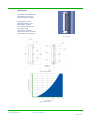
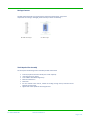
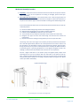
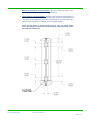
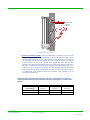
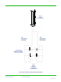
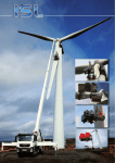
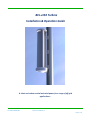
BEL-v150 Turbine
Installation & Operation Guide
A silent and robust vertical axis wind power for a range of off-grid
applications...
Tel: +4021.326.81.89
www.rominstalsolar.ro
Page 1 of 15
Contents
Contents ................................................................................................................. 2
Read this first ........................................................................................................ 3
Introduction ........................................................................................................... 4
Safety Precautions ................................................................................................. 5
Specifications ......................................................................................................... 6
Package Contents .................................................................................................. 7
Tools Required For Assembly ................................................................................. 7
Mechanical Assembly Procedure ........................................................................... 8
Electrical Installation ........................................................................................... 11
Turbine Operation ............................................................................................... 14
Maintenance ........................................................................................................ 15
Warranty Registration
Please register your product with us so that we can administer your
warranty entitlement.
Customers are required to keep an original copy of their invoice
should questions arise requiring reference to purchase information.
Tel: +4021.326.81.89
www.rominstalsolar.ro
Page 2 of 15
Read this first
1. Don’t connect the wind turbine in the wrong polarity
Make sure you connect the +ve of the turbine to the +ve of the battery (red to
red) and the -ve of the turbine to the -ve of the battery (black to black). Failing
to do so will damage the equipment and invalidate your warranty.
2. Don’t connect the Diversion Charge Controller in series with the turbine
If you choose to install a diversion charge controller (optional), always ensure
that the turbine and the controller are connected to the battery separately.
3. Don’t allow the turbine to run without being connected to the battery
Failing to do so will result in the turbine freewheeling causing premature
wear and tear and unnatural blade noise.
Tel: +4021.326.81.89
www.rominstalsolar.ro
Page 3 of 15
Introduction
Please read this manual thoroughly before attempting to assemble, install or operate your BELv150 small wind turbine. This will assure optimum performance and safety.
The BEL-v150 turbine features an array of innovations and construction techniques as well as
heavy-duty engineering to ensure optimum efficiency and a long operating life.
The BEL-v150 has been designed to be simple, economic, durable and yield excellent performance.
Specific BEL-v150 turbine features:
•
•
•
•
•
•
•
•
Innovatively designed axial flux alternator, using neodymium iron boron magnets
Bearing support at both ends of the savonious rotor to provide stability and longevity
Maintenance-free, low friction bearings
Silent operation
Easy installation
Simple design for low cost and durability
Fully marinised using stainless steel fixings and anodised aluminium components
Low mass to help reduce exerted forces and ensure easy installation.
BEL-v150 has been designed to for both land-based and marine environments. Thanks to its unique
design, the BEL-v150 will suffer minimal corrosion in both normal and salt water operating
conditions.
Applications include:
•
•
•
•
•
Tel: +4021.326.81.89
Marine trickle charging
Supplying power for DAQ and environmental monitoring
Monitoring sites
Telecommunications
The Developing World.
www.rominstalsolar.ro
Page 4 of 15
Safety Precautions
Safety must always be your primary concern during the assembly, installation and operation of your
BEL-v150 turbine. Always be aware of the risks involved with mechanical and electrical installation
work. If in doubt about any issue regarding your turbine, please seek further assistance before
proceeding. Installation of the BEL-v150 turbine should only be undertaken by suitably competent
and qualified personnel.
Mechanical Safety Hazards
•
The main rotor is the most obvious and serious mechanical safety risk. When the turbine is
operating at its rated performance, the blades may be very difficult to see, due to the
speed of rotation. Never approach the turbine whilst it is operating at speed. Ensure that
the turbine is installed in a suitable position where nobody can interfere with the rotor
blades.
•
Working with tools of any kind can be dangerous. Your BEL-v150 turbine requires some
basic mechanical assembly with rudimentary hand tools. If you are in any doubt about how
to use these tools correctly, please seek advice from a suitably experienced person.
Your BEL-v150 turbine will inevitably be installed upon a mast or tower or other support
structure. This may mean working at height. Always ensure that all personnel in the
immediate vicinity are aware of any lifting / hoisting operations that will be occurring.
Check there are no loose components or tools likely to fall and cause injury during the
lifting operation. Where possible, all assembly work should be completed at ground level.
Ensure that the batteries are disconnected during the installation procedure.
Twist the turbine output cables together (to create a short circuit) during the mechanical
installation process. This will prevent the turbine from ‘spinning up’ during the installation.
Never install the turbine upside down or in any orientation other than that depicted on the
installation instructions.
Install your turbine during a calm day.
•
•
•
•
•
Electrical Safety Hazards
• The BEL-v150 generates rectified DC voltage. Even at these low voltages there are inherent
risks. Caution should always be used when connecting the BEL-v150 to the electrical
system.
• Ensure that you have followed the cable-sizing chart to ensure that the correct size of
transmission cable has been selected. If a cable of insufficient cross-sectional area is used,
heat may build up in the cables causing a potential fire hazard. Using cables of insufficient
cross-sectional area may also reduce the power transmission efficiency of the turbine.
•
•
•
Battery systems can deliver a serious amount of current. A short circuit in the battery
circuit can lead to hundreds of amps flowing through the battery cables. This will cause a
heat build-up and ultimately an electrical fire. Batteries can explode when shorted. Always
use insulated electrical tools when working on the battery’s electrical connections.
Batteries are very heavy. Do not attempt to move batteries by yourself. Always use manual
handling tools and an assistant.
Always keep lead-acid batteries the correct way up. Do not allow the acidic electrolyte to
spill or come into contact with your skin or face. Always follow the manufacturer’s safety
instructions when handling lead-acid batteries.
Please use common sense when installing and operating your turbine!
Tel: +4021.326.81.89
www.rominstalsolar.ro
Page 5 of 15
Specifications
Turbine Name: BEL-v150 Turbine
Part Number: GA-LETU-013
Nominal Voltage: 12 / 24V DC
Rotor Diameter: 270 mm
Rated Wind Velocity: 8 m/s
Rated Output: 24 Watts
Start-up Wind Velocity: 4 m/s
Total weight: 13 Kg
Tower mount: see below
Chassis Construction: Aluminium
Rotor Blades (3-off): Aluminium
Fig-1: Side View
Fig-2: Operating Envelope
Fig-3: Energy Conversion
Tel: +4021.326.81.89
www.rominstalsolar.ro
Page 6 of 15
Package Contents
Your BEL-v150 turbine will arrive containing the components shown below. If any of the
components are missing or damaged, please contact your dealer immediately.
BEL-v150 Turbine: Qty 1
User Manual: Qty 1
Tools Required For Assembly
You will require the following tools to assemble your BEL-v150 turbine:
•
•
•
•
•
•
•
Tel: +4021.326.81.89
13 mm A/F spanner & 13 mm ratchet (one of each required)
8mm A/F spanner or ratchet
A set of Metric Standard Hexagon Keys
Electrical screw drivers
Power drill
8.5 mm diameter twist drill bit, suitable for drilling through steel (if standard mount
brackets are being used)
Digital multi-meter capable of measuring DC Volts
www.rominstalsolar.ro
Page 7 of 15
Mechanical Assembly Procedure
1) Unpacking - Inspect the contents of the box and ensure that all items are present and free
from damage. If any of the components are missing or damaged, please contact your
dealer immediately.
2) Check Main Rotor & Continuity - Ensure that the main rotor is free turning and does not
scrape or rub as it rotates - see Fig 4. As the turbine is shipped in a horizontal orientation, it
may be the case that the upper or lower stub shafts or cowlings have shifted during transit.
If the turbine blades feel stiff and do not rotate freely, follow the below steps to reset the
stub shaft positions:
A)
B)
C)
D)
E)
F)
Remove the M5 cowling fixings and then the cowlings themselves.
Slightly slacken the M5 fixings on the upper and lower stub shafts.
Hold the turbine vertically and rotate the main rotor blades.
The stub shafts will now reposition themselves and the turbine will rotate freely.
Retighten the upper and lower stub shaft fixings and check that the turbine still
rotates freely.
Reposition and fix the cowlings ensuring that they do not rub upon each other..
The bearing units used in the magnet rotor assembly are factory lubricated and sealed for
life. It will take approximately 100 hours of normal operation for the seals to ‘bed-in’ and
the lubrication to be distributed correctly around the bearing raceways and ball cages.
During this period you may notice a reduced performance caused by the additional friction
of the bearing seals. In operating temperatures of –10 degrees Centigrade or lower, this
‘bedding-in’ period will be extended by a further 50 hours of normal operation.
Connect a digital multi-meter to the positive (red) and negative (black) output leads
extending from the rear of the turbine. With the multi-meter set to detect DC Volts (020V), a voltage should be displayed when the main rotor is spun by hand. This voltage will
vary with the speed of rotation. If no voltage is detected whilst turning the rotor, please
contact your dealer immediately.
Upper Stub Shaft Fixings
Upper Stub Shaft Fixings
Fig-4: Checking main rotor rotation and voltage output
Tel: +4021.326.81.89
www.rominstalsolar.ro
Page 8 of 15
3) Remove the turbine from the transit packing – Use a pair of 13mm A/F spanner and or
ratchet to remove the M8 fixings from the transit base board.
4) Fix the turbine in its mounting Position – With the turbine removed from the baseboard, it
can now be fitted in its intended position. The BEL-v150 is supplied as standard with three
universal flat mounting brackets. Dimensions of the brackets can be found below in fig 5.
Alternative mounting brackets are available from Leading Edge Turbines.
Ensure that the turbine is mounted vertically and on a flat and smooth surface.
Incorrectly mounting the turbine may cause the main spine to distort which may result in
the turbine not rotating freely.
Tel: +4021.326.81.89
www.rominstalsolar.ro
Page 9 of 15
8.6mm Dia
Mount
Points
Fig-5: Mount the turbine in position
5) Install the Transmission Cables- Follow the table below to select the correct wire size
(cross-sectional area). This will vary depending on your nominal battery voltage and the
distance that the cables will be run. Careful selection of the cable size is required. It will
not only affect the safety of the system, but also the overall efficiency. A cable of
insufficient cable size will cause a voltage drop, wasting the power that has been
generated. The cable sizes listed below have been selected with efficiency and cost in
mind, as it is unlikely that your turbine will be running at full capacity 100% of the time. If
in doubt, consult your local electrical supplier. The cable should be installed in accordance
with local electrical regulations and guidelines. If in doubt, use a local electrical contractor
to complete the cable installation. Once the transmission cable installed, it can be
connected to the BEL-v150.
Warning: If a cable of insufficient cross-sectional area is used, heat will build up in the cables
causing a potential fire hazard. Cable capacities quoted below are based upon ‘Tri-Rated’ cables
(BS6231).
BEL-v150 Nominal
Output Voltage
12 Volts
24 Volts
Tel: +4021.326.81.89
Transmission Distance
30 Metres
(90 Feet)
100 Metres
(300 Feet)
1.5 mm²
4 mm²
Not Recommended
1.5 mm²
2.5 mm²
10 mm²
10 Metres
(30 Feet)
www.rominstalsolar.ro
Page 10 of 15
Electrical Installation
Please refer to Figs 6 for appropriate generic wiring diagrams. In a battery charging renewable
energy system there may be different ways of wiring small wind turbines, photovoltaic panels,
charge controllers and batteries together. This type of system will often expand ‘organically’, but
the following guidelines should be followed:
•
Follow the appropriate electrical code - The electrical wiring of your BEL-v150 turbine and
associated electrical systems must be done in accordance with national and local electrical
codes and regulations.
•
Do not connect the turbine or batteries during the installation - Ensure that the turbine is
not running or connected to the batteries during the installation or wiring process.
Connect the output cables of the turbine together to prevent the rotor from starting up.
•
Galvanic corrosion of electrical joints - Try to avoid connections between dissimilar
metals. For example, connecting copper and aluminium together will result in galvanic
corrosion of the connection. This will increase the electrical resistance of the connection
(wasting energy), and reduce the mechanical integrity of the joint. Where possible, use a
fluxed solder to make electrical joints.
•
Protect the cables - The power transmission cables must be protected from mechanical
damage and fatigue. Run the cables through an approved conduit / trunking.
•
Cable strain relief - Prevent mechanical strain on the transmission cables running down
the tower from the turbine. Clip the cables to the inside of the tower. Failure to do this will
result in excessive mechanical strain on the cable joints within the slip-ring assembly and
may cause a failure. Cable ties or cable glands are a good way to prevent mechanical strain
on the cables.
•
‘Earth’ the System - The turbine tower should have its own separate earth point. The
negative terminal of the battery bank should also be earthed. This provides protection
against the build-up of static and lightning strikes. The tower should be earthed separately
with its own ground rod if there is a long transmission distance between the tower and
batteries. An appropriate surge arrestor could also be used to help prevent damage to the
battery charging system during a lightning strike. Ensure that the earth cables are of the
same rating as the positive and negative cables.
•
Cable Selection - The cable size table should be used to select the minimum sized cable for
a given transmission distance. Voltage drop in the cable will be improved if a larger cable is
used.
•
Fuses - The turbine and charging circuit should be protected with a suitably rated ‘slowblow’ DC fuse or DC circuit breaker. Please refer to the table below for the correct rating.
The fuse or breaker should be positioned between the turbine and batteries (on the
positive cable). If a stop switch is used (recommended) the fuse should be positioned
between the switch and the batteries.
BEL-v150 Nominal
Output Voltage
12V
24V
Tel: +4021.326.81.89
DC Fuse / DC Circuit Breaker Rating
20 Amp
10 Amp
www.rominstalsolar.ro
Page 11 of 15
•
Run / Stop Switch - A simple switch arrangement can provide a safe and easy way of
stopping the turbine during high winds, or for maintenance. BEL turbines can supply a
switch which is best for this purpose. As the switch is thrown, the batteries are
disconnected and the turbine is ‘shorted’ reducing the rotor to a slow rotation. Refer to
the generic wiring diagrams. A run / stop switch is optional on the BEL-v150 turbine. See
Appendix for more information.
•
Charge Controllers – We recommend that the BEL-v150 is used with our BEL-300 diversion
charge controller. A diversion charge controller works as an 'overflow' for your batteries
and protects them against becoming overcharged. A diversion charge controller is a
separate electrical entity and is wired directly onto the battery bank in parallel with the
turbine. When the BEL-v150 is to be used in a hybrid system with multiple power sources
such as solar PV, we recommend that you use our 45A diversion charge controller and
separate dump load - This provides a flexible system that is able to accommodate different
charging systems.
We do not recommend that any other type of charge controller is used with the BEL-v150
turbine - This may cause damage to the turbine or the charge controller.
Please refer to the following wiring diagrams as a guide.
Tel: +4021.326.81.89
www.rominstalsolar.ro
Page 12 of 15
BEL-150
TURBINE
(PN: GA-LETU-013)
-VE
Transmission
Cable (Black)
+VE
Transmission
Cable (Red)
+
+
-
-
BATTERY BANK
(WIRED TO APPROPRIATE
CAPACITY & VOLTAGE)
+
-
+
-
DL-300
CONTROLLER
(REQUIRED)
PN: GA-CTRL-001A
Fig-6: Simple ‘Stand-Alone’ battery-charging wiring diagram
Tel: +4021.326.81.89
www.rominstalsolar.ro
Page 13 of 15
Turbine Operation
The BEL-v150 turbine is based on a simple design for ease of installation and reliable operation. You
may notice the following behaviour during normal operation:
Tel: +4021.326.81.89
•
Cut-in - The turbine will not begin to charge the batteries until the rotor is spinning at
approximately 120 RPM. Whilst operating below this speed, the turbine will be ‘off-load’
and freewheeling. Once the turbine output voltage becomes equal to the nominal battery
voltage (at around 120 RPM), the turbine will come ‘on-load’ and begin to deliver current
to the batteries. During the off-load stages of rotation, the rotor blades rotate very freely.
This allows the rotor to build up speed and allows aerodynamic lift to be generated by the
blades.
•
Normal Operation - Once the rotor is spinning at 120 RPM, current will be delivered to the
batteries. As the rotor speed increases, so too will the current and voltage.
•
Shut Down (If Run / Stop switch is fitted) – A run / stop switch is not required with the
BEL-v150 turbine but one can be installed if desired (see appendix 2). By activating the stop
switch, the output cables of the turbine are ‘shorted’ together. This effectively puts an
infinite load on the generator causing the turbine to stall. When the stop switch is
activated the turbine may still rotate slowly during high winds, but the rotor blades will not
be able to build up any significant speed. It is not recommended that the stop switch is
activated whilst the rotor is spinning at high speed. This sudden braking action will stress
the blades and other components. Only activate the stop switch during a ‘lull’ when the
rotor is not spinning excessively fast.
•
High Winds - Every effort has been taken to ensure that the BEL-v150 will withstand the
forces exerted by strong winds. The turbine will continue to generate power whilst
surviving the immense forces that are exerted by high winds.
www.rominstalsolar.ro
Page 14 of 15
Maintenance
Please follow the preventive maintenance programme listed below. This will ensure that the
turbine operates reliably and safely with good efficiency.
Always shut down the turbine before attempting to carry out maintenance.
Post-Installation Checks (to be carried out one month after installation):
• Check that the turbine mount fixings are secure and has not worked loose. Adjust if
required.
• Ensure that the rotor blades rotate freely.
• Ensure that all electrical connections are sound.
Annual Maintenance:
• Inspect the turbine & support structure.
• Ensure that the bearings are smooth and free running.
• Inspect the rotor blades for damage such as dents or chips. The blades will become
unbalanced if they are damaged. This will cause vibration, noise and poor performance. If
many dents have occurred along the edges of the blades, a new set of rotor blades should
be fitted (part numbers available in the Spares section).
• Remove any build-up of dirt and debris from the rotor blades using a mild detergent and
warm water.
• Check the blade fixings for tightness.
• Check that all electrical connections are sound and free from corrosion.
• Generally ensure that the turbine is in good working condition and is safe for continued
use.
After five years of normal operation:
• We recommend that the rotor bearings should be replaced after five years of continuous
operation. This will ensure that the turbine’s performance and safety is not compromised.
Other Considerations:
• The equipment used in the charging system (batteries, charge controller, PV panels,
invertors, etc.) should be maintained according to the instructions published by the
relevant manufacturer.
• Where lead-acid batteries are used, it is especially important that they are maintained
carefully. Failure to do so will result in the batteries being rendered useless within a short
period of time.
Tel: +4021.326.81.89
www.rominstalsolar.ro
Page 15 of 15