1
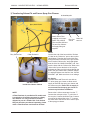
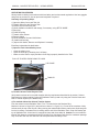
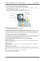
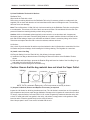
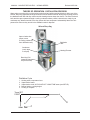
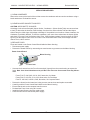
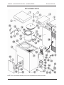
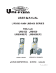
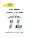
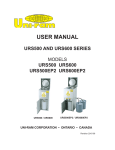
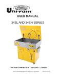
USER MANUAL
URS900 SERIES
URS900
URS900EP2
UNI-RAM CORPORATION • ONTARIO • CANADA
Revision 2007-09A
MANUAL - SOLVENT RECYCLERS - URS900 SERIES
Revised 2007-09A
CONTENTS
INTRODUCTION ................................................................................................................................... 3
SAFETY APPROVALS, CAUTIONS AND WARNINGS ........................................................................ 3
FEATURES AND SPECIFICATIONS .................................................................................................... 4
SAFETY FEATURES ............................................................................................................................ 4
PREPARATION AND SETUP, INCLUDED PARTS, ADDITIONAL PARTS ........................................... 5
LOCATION AND CONNECTION ......................................................................................................... 5
SOLVENT REQUIREMENTS AND DEFINITIONS ................................................................................ 6
INSTALLATION OF SOLVENT TRANSFER HOSES AND THE AIR SUPPLY KIT (EP2 MODELS) ... 6-8
OPERATING PROCEDURES ........................................................................................................... 9-12
THEORY OF OPERATION ................................................................................................................. 13
TROUBLESHOOTING GUIDE .......................................................................................................... 14-15
TEST MODE ....................................................................................................................................... 15
ERROR MESSAGES ....................................................................................................................... 16
SERVICE PROCEDURES INCLUDING 6-MONTH MAINTENANCE ............................................... 17-18
REPLACEMENT PARTS .................................................................................................................... 19-20
WARRANTY ....................................................................................................................................... 21
2
MANUAL - SOLVENT RECYCLERS - URS900 SERIES
Revised 2007-09A
INTRODUCTION
Uni-ram holds many patents on designs used in its innovative products. Every machine is tested for compliance with Quality Assurance standards. Follow the instructions on preparation, use and operation to
operate this machine safely and effectively. Ensure that this manual is readily available to the operator at
all times. If you have any questions about the operation of this machine, contact:
North America:
Uni-ram Technical Service
1-800-417- 9133
Other Continents:
Contact Your Supplier
SAFETY APPROVALS
This unit is certified under UL standards U2208 and CSA standards C22.2 No. 30 and No. 88 by ETL for
use in non-hazardous locations as well as for use in hazardous locations Class 1, Division 1, Group D
– T2C and and Class 1, Division 2, Group D -T2C.
CAUTIONS AND WARNINGS
•
•
•
•
•
•
•
•
•
•
Wear protective clothing according to local safety and environmental regulations, with a minimum of
face goggles, gloves and mask.
Disconnect from the power source before performing maintenance.
DO NOT SMOKE OR USE THIS EQUIPMENT NEAR A POTENTIAL SOURCE OF IGNITION SUCH
AS SPARKS OR AN OPEN FLAME. This unit must be located at least 15 feet (4.6 m) from all potential sources of ignition including electrical receptacles, switches, pilot lights, fixtures and contacts when
installed in non - hazardous locations.
The ambient temperature must be between 5°C (41°F) and 35°C (95°F).
Do not distill solvents which may contain Nitrocellulose or any other unstable components.
Do not distill solvents with an Ignition Temperature lower than 250°C (482°F).
Do not install, operate or maintain this unit in a location where the Ignition Temperature of the hazardous atmosphere(s) is lower than 250°C (482°F).
Solvents that are recycled can be flammable. Establish and follow safe pratices to store and handle
solvents. Such safety procedures will result in safely contained solvents free from spillage.
Units must be installed by a qualified electrician.
Install on a dedicated circuit with sufficient current capacity (see specifications section).
3
MANUAL - SOLVENT RECYCLERS - URS900 SERIES
Revised 2007-09A
FEATURES AND SPECIFICATIONS
All Uni-ram Solvent Recyclers feature rapid-start direct electric heating of solvent (so there is no diathermic oil to change) as well as high-efficiency condensers, air cooled with a motor driven fan. All of the
Recyclers can be used with any Uni-ram Automatic Apray Gun Cleaner. The “E” models are designed to
be linked directly to a Uni-ram “E” series Automatic Spray Gun Cleaner or to an external container. The
direct connection creates a self-contained Recycling System allowing Timer-controlled Transfer In and
Out between the Solvent Recycler and the other component.
MODEL
URS900
URS900EP2
VOLTAGE (V)
220/240
220/240
CURRENT (A)
9.2-10
9.2-10
15
15
RECOMMENDED CIRCUIT AMPS
MAX TEMPERATURE SET POINT
TIME TO RECYCLE
TANK CAPACITY
CONSENSER AND FITTING
LID GASKET
200°C
200°C
4-6 HOURS
4-6 HOURS
6.6 US GAL (25L)
6.6 US GAL (25L)
COPPER**
COPPER**
NEOPRENE***
NEOPRENE***
SOLVENT TRANSFER SYSTEM
NO
YES
SHIPPING DIMENSIONS (WDH”)
31 X 30 X 45
31 X 30 X 45
175/80
175/80
WEIGHT (LB/KG)
** ALSO AVAILABLE IN STAINLESS STEEL
*** ALSO AVAILABLE IN TEFLON ENCAPSUALTED RUBBER
Safety Features:
• Certified to UL standards U2208 and CSA standards C22.2 No. 30 and No. 88 by ETL. Approved
for use in non hazardous locations as well as approved for use in hazardous locations Class 1,
Division 1, Group D and Class 1, Division 2, Group D.
• Explosion proof construction and intrinsically safe electric circuitry.
• Computer controlled with many built-in safety programs including temperature control of all critical points including tank, condenser and fan motor. Power is cut when the temperature at any of
these points rises above a pre-set level. Operation also terminates when other abnormal conditions
exist (eg: boiling does not start on time or the distillation process takes too long).
• Automatic pressure relief lid system prevents pressure in the Distillation Tank from exceeding 0.5
to 1.0 psi. (0.035 to 0.070 kg/cm2).
• Self Diagnostic error messages are displayed on the Display Panel.
• Dual lid cover system.
• Compact, enclosed cabinet for safe storage of the Solvent Receiving Container inside the cabinet.
Operating Features:
• Rapid-start due to direct electric heating of solvent, no diathermic oil to change.
• Short cool-down time. High efficiency condenser, air cooled with motor driven fan.
Warranty: 1 year on unit, 2 years on pump.
4
MANUAL - SOLVENT RECYCLERS - URS900 SERIES
Revised 2007-09A
PREPARATION AND SETUP:
•
•
•
•
•
•
•
Carefully inspect the shipping carton for any sign of transport damage.
Carefully remove the unit from the shipping carton.
Check the unit for damage. Report any transport damage immediately to the carrier and your
vendor. Initiate a freight claim with the carrier. The manufacturer is not responsible for freight damage.
A Liner Bag and Retainer Ring are already installed inside the distillation tank.
Check the Accessory Kit for the parts listed below. If any parts are missing, contact your supplier. Additional consumables and accessories are also listed.
Level the unit using the adjustable feet and install the Door Handle.
For models with the Solvent Transfer System (EP2 Models), install the Solvent Transfer Hoses and the
Air Supply Kit. (See instructions on Pages 7-8).
ACCESSORY KIT (Included Parts)
All Models
Replacement Part Number
Manual
NA
Airline Filter
10-220
Lid Gasket, Standard (Neoprene)*
770-2150N
Liner Bag, 2 Spares
See below for re-order numbers
Door Handle & 2 Screws
120-318 & 909-404S
Solvent Outlet Tube
770-8131
CAUTION:
EP2 Models Only
Transfer Hoses and Fittings (EP2 Series)
KIT-TRANSHOSES-A
Air supply Kit (EP2 Series)
KIT-AIRSUPPLY-E
*Not included with Models using Teflon Gaskets
ADDITIONAL CONSUMABLES, ACCESSORIES AND REPLACMENT PARTS
Receiving Container, Stainless Steel
900-9010
Lid Gasket, Standard (Neoprene)
770-2150N
Lid Gasket, Special (Viton)
770-2150V
Lid Gasket, Special (EPDM)
770-2150E
Lid Gasket, Special (Teflon Encap.)
770-2150TE
Retainer Ring
770-9110
Spill Containment pail
100-041
Fuse Kit
KIT-FUSE692
Liner Bag, Standard, Pkg of 10
LB900C-10
Liner Bag, Standard, Pkg of 100
LB900C-100
Liner Bag, Standard, Pkg of 250
LB900C-250
Liner Bag, Standard, Pkg of 1000
LB900C-1000
USE ONLY GENUINE UNI-RAM
LINER BAGS WHICH ARE 2 MIL
THICK, LIGHT BLUE IN COLOUR
WITH A SAWTOOTH EDGE AND A
3/16” WELD.
THEY ARE SPECIALLY MANUFACTURED TO BE STRONG, HEAT
RESISTANT AND CHEMICAL
RESISTANT.
USE OF A NON-UNI-RAM LINER
BAG MAY VOID THE WARRANTY.
LOCATION AND CONNECTION:
This unit is certified for use in non-hazardous locations and hazardous locations
Class 1, Division 1 Group D and Class 1, Division 2, Group D.
•
Non-hazardous Location:
If using a non-hazardous plug, the unit must be located outside of a hazardous location. In a non-hazardous location, we recommend that you use a receptacle located a minimum of 6 feet (185 cm) from
the unit and a minimum of 30” (80 cm) from the floor. We also recommend that the unit be located at
least 6 feet from any potential source of ignition such as electrical receptacles, switches, pilot lights,
fixtures, contacts and similar equipment. To clarify the definition of an appropriate location, contact
your local authority. This unit must be connected to the power supply only by a qualified electrician in
accordance with the National Electrical Code.
5
MANUAL - SOLVENT RECYCLERS - URS900 SERIES
•
Revised 2007-09A
Hazardous Location:
In hazardous locations (Class 1, Division 1, Group D and Class 1, Division 2, Group D), the power
cord must be connected to the main power supply by a qualified electrician, in accordance with the
National Electrical Code. An explosion proof outlet (receptacle or hard wired) must also be used.
Select a Location That Meets EACH AND EVERY Requirement, Described Below.
1) Comply with the instructions in the section: CAUTIONS AND WARNINGS.
2) Position the solvent recycler in a location so that there is at least 6 inches (15 cm) of space all around
the unit. Ensure that the safety lid and door freely opens fully and a container for receiving the distilled solvent can freely move in and out of the cabinet. The unit must be in a location where people or
equipment cannot disturb the power cord or connection. The cord must be connected directly to the
main power supply; an extension cord cannot be used.
3) Connect the unit to a dedicated 20A, 200/240V branch circuit.
On first power up and when the unit is ready to begin a new cycle, the Display Panel shows
“READY S.P. = XXX°C”.
SOLVENT REQUIREMENTS
This unit recycles flammable solvents and combustible solvents. Flammable solvents include lacquer thinner, paint thinner, acetone and other paint diluents. Flammable Solvents have a flash point below 38.7°C
(100°F). These solvents are commonly used in the industry as cleaning solvents or paint diluents.
Dirty solvent to be distilled must meet each requirement described below. The Material Safety Data
Sheet (MSDS) provides data on the properties of the virgin solvent.
1) The BP (Boiling Point) of the dirty solvent must be less than 200°C (392°F). BP increases with greater
contamination.
2) The auto-ignition temperature of the solvent to be distilled must be higher than 250°C (482°F) for safe
operation. Do not recycle Nitrocellulose. The auto ignition temperature is 135°C (275°F).
Notes:
•
Recycle recently contaminated solvent only. Standing solvent can become acidic over time.
•
To avoid “FISH EYE” problems, do not recycle both paint dilutents and parts washer solvent in the
same unit.
Definitions
Flash Point:
The lowest temperature at which the vapor of a solvent can be made to ignite momentarily in air.
Auto-ignition Temperature (often referred to as “ignition Temperature” or “Ignition Point”):
The temperature at which solvent ignites by itself.
INSTALLATION OF SOLVENT TRANSFER HOSES AND THE AIR SUPPLY KIT (EP2 MODELS ONLY)
1) Transferring Solvent To and From a Spray Gun Cleaner
2) Transferring Solvent To and From a Drum / Container
3) Stand-alone Operation
For the URS900 (Non-EP2) Models, use 3) Stand-alone Operation
6
MANUAL - SOLVENT RECYCLERS - URS900 SERIES
Revised 2007-09A
1) Transferring Solvent To and From a Spray Gun Cleaner
Solvent Recycler
Spray Gun Cleaner
Attach Airline Filter
(supplied) to Air Input
Dirty Sol- Clean Solvent Out
Attach Tee to Airline
vent In
Filter and Blue Airline to
Tee and Gun Cleaner
Air Supply fitting not
supplied
Dirty Solvent Out
Hoses:
Connect the end of the hose with the “Solvent
In” label to the “Solvent In” port on the recycler.
Hand tighten. Pass the other end of this hose
through the hole in the back of the gun cleaner
that is marked “Solvent Out” and hand tighten
onto the lid of the “WASH SOLVENT” pail. Connect the hose with the “Solvent Out” label to the
“Solvent Out” port at the back of the recycler
and pass the other end of this hose through the
hole in the gun cleaner that is marked “Solvent
In” and hand tighten onto the lid of the “CLEAN
SOLVENT” pail. Make sure there is no leakage.
Clean Solvent In
Air Supply:
The blue airline and Tee are for use with an
“E” series spray gun cleaner to allow one air
supply to feed both the spray gun cleaner and
the solvent recycler. Ensure the air supply is
not connected to the spray gun cleaner or
solvent recycler before installation.
SOLVENT PAILS
Inside Gun Cleaner Cabinet
NOTE:
A Flow Restricter is provided on P2 models and
is required on all models connected to a Spray
Gun Cleaner. It is only provided on models
shipped as part of a Combo Unit. If the Solvent
Recycler has been purchased separately, please
order a Flow Restricter and install as directed.
7
Remove the 2 airline connectors from the “T” .
Connect the male port of the “T” to Air Inlet of
the recycler. Connect the Airline Filter. Connect
one end of the blue airline to the “T”. Connect
the other end of the blue air line to the Air Input
of the spray gun cleaner.
MANUAL - SOLVENT RECYCLERS - URS900 SERIES
Revised 2007-09A
2) Connecting Hoses for Transferring Solvent To and From a Drum / Container
Attach Airline Filter
(supplied) to Air Input
Air Supply fitting not
supplied
Dirty Sol- Clean Solvent Out
vent In
Connect the end of the hose with the “Solvent In” label to the “Solvent In” port on the recycler. Hand tighten. Connect the other end of the hose to the 3 ft suction pipe using the hose clamp. Insert the 3 ft suction
pipe into the drum / container of dirty solvent. Connect the other hose with the 4 3/8” suction pipe to the
“Solvent Out” port on the recycler and place the suction pipe into a clean drum / container large enough to
receive the clean, recycled solvent.
Air Supply:
The blue airline and Tee are for use with an “E” series spray gun cleaner to allow one air supply to feed
both the spray gun cleaner and the solvent recycler. It is not used in this situation. Connect the Airlune
Filter directly to the Air Input port of the Solvent Recycler and attach a suitable Air Supply Fititing (not supplied).
3) Stand-alone Operation
For the URS900, stand-alone opeartion is standard and this model does not have the
ports shown above.
8
MANUAL - SOLVENT RECYCLERS - URS900 SERIES
Revised 2007-09A
OPERATING PROCEDURES
Wear protective clothing in accordance with local safety and environmental regulations. Use face goggles
and gloves as a minimum. Use an apron and respirator if required.
Summary of Operating Steps:
1) Open the Safety Cover and Tank Lid
2) Transfer Solvent to the Recycler Tank
3) Position Solvent Receiving Pail
4) Check distillation conditions and change, if necessary, using SETUP MODE.
5) Recycling
6) Finish Recycling
7) Transfer clean solvent
8) Remove debris
9) Clean Distillation Tank and Lid Surface
10) Install new liner bag
11) Inspect Lid Gasket, Remove and Replace if necessary
Each Step is described in detail below.
1) Open the Tank Lid and Safety Cover
•
•
•
Open the safety cover.
Open the inner lid by releasing the Lid Clamp.
Make sure that Tank is empty and that a Liner Bag is properly installed in the Tank.
PULL UP TO OPEN. PUSH DOWN TO LOCK
LID CLAMP
TANK LID
2) Transfer Solvent To the Recycler Tank
Verify that the solvent to be recycled complies with the requirements described in the section, Solvent
Requirements. Solvent can be put into the Distillation Tank by hand or by using the Transfer Hoses and
bulit-in Transfer System (EP2 Models only).
a) For models without the Solvent Transfer System
Pour the solvent into the Distillation Tank. Fill to 1.5 inches below the Retainer Ring.
Maximum volume is 6.6 gal (25 L) and minimum volume is 1.5 gal ( 6 L). Do not let the container of dirty
solvent touch the top of the recycler. When pouring the contaminated solvent, make sure all solvent goes
into the Liner Bag, not between the Liner Bag and the wall of the Distillation Tank. Clean Lid Gasket and
top of distillation tank. Close inner lid, engage lid clamp and close safety lid. Caution: Do not overfill Distillation Tank because contaminated solvent could flow into Condenser and block the condenser passage
way. Close the Tank Lid, lock down the Lid Clamp and close the safety Cover.
9
MANUAL - SOLVENT RECYCLERS - URS900 SERIES
Revised 2007-09A
b) For models with the Solvent Transfer System (EP2 Models):
•
•
•
•
Open the Transfer Valve by turning the handle counter-clockwise 90°.
Turn the Filling Timer knob clockwise fully. Dirty solvent will flow from the Transfer Port into the Liner
Bag and stop when the timer runs out.
Close the Transfer Valve by turning the handle clockwise 90°.
Close the tank Lid, lock down the Lid Clamp and close the safety Cover.
Transfer Timer
Lid Gasket
Filling Timer
Transfer Valve
Transfer Port
3) Position Solvent Receiving Pail
a) For models without the Solvent Transfer System
Open the Door and position a Solvent Receiving Pail (not provided) with a minimum size of
5 US Gal (20 L) inside the cabinet. Insert the Solvent Outlet Tube (short and curved) into the top opening
of the pail. The Solvent Outlet Tube must extend below the rim of the pail to prevent solvent spillage. If
the pail is metal, connect the alligator clamp of the Ground wire to the rim of the pail. Close the door.
b) For models with the Solvent Transfer System (EP2 Models):
Open the Door. A special, connected, plastic Solvent Receiving Pail is provided. Check to make sure that
the Solvent Outlet Tube (short and curved) is inserted into the hole in the top of the pail and that the Pick
Up Tube (long and straight) is tightly attached to the Quick Connect fitting.
4) Check distillation conditions and change, if necessary, using SETUP MODE.
Estimate Boiling Point
Add 40°C (100°F) to the boiling point of the pure solvent as shown on the MSDS (Material Safety Data
Sheet) or another reliable source.
Recycle more often
The boiling point of the waste solvent mixture increases as it gets dirtier. To reduce the boiling point,
recycle more often.
Minimize Temperature Set Point
After recycling there will be a small amount of solvent, about 1/8 US gal (500 ml), remaining in the distillation tank due to condensation. Select the lowest Temperature Set Point that recycles the solvent to this
level.
If all the settings are acceptable, press START to begin distillation.
To change settings, enter Setup Mode
10
MANUAL - SOLVENT RECYCLERS - URS900 SERIES
Revised 2007-09A
SETUP MODE
To change settings, enter Setup Mode: while pressing SETUP, press START. “SET-UP MODE” is displayed. To change the temperature units from °C to °F, press and hold the + and - keys together
for 2 seconds.
STEP SETTING
1
2
ADJUST ACCEPT DESCRIPTION
SET-PT = XXX°C (°F)
POWER = XXX%
+ OR -
+ OR -
OK
To choose a SET POINT, look up the solvent’s BP
(boiling point (MSDS, online etc) and add about
40°C (100°F).
OK
If boiling is too vigorous due to one or more of the
following conditions, decrease POWER by one
increment or more.
• vapour leaks at the Lid Gasket
• recycled solvent comes out too hot
• waste material is carried into the recycled solvent
Otherwise, use 100%.
3
SHUT-OFF = AUTO**
+ OR -
OK
If too much solvent remains in the Distillation Tank
after recycling and the problems in the Troublshooting Guide have been ruled out, over-ride
the AUTO SHUT-OFF and manually select a heating time (eg: 4 hours). The heater will stay on for
this amount of time and then cooling will begin.
4
BAKE TIME = XXM
+ OR -
OK
Only available when SHUT-OFF = AUTO. Increase if residue (puck) is too wet.
**WARNING: SHUT-OFF TIME MUST NOT BE SET TO MORE THAN 8 HOURS MAXIMUM
5) Recycling
On first power up and when the unit is ready to begin a new cycle, the Display Panel shows
“READY S.P. = XXX°C” (S.P. = SET POINT). When Setup is complete and START has been pressed,
the “HEAT” light comes on and the recyling process begins. During the boiling phase, 3 temperatures
will alternate on the Display: “SET-PT”, “TANK” and “VAPOR EX.” When the boiling phase is complete,
“COOLING” will be displayed. Note: the fan may still be running; this is normal as it continues to run until
the temperatue drops below 50°C. To cancel the cycle, press the “START/STOP” key.
6) Finish Recycling
CAUTION: DO NOT OPEN LID UNTIL COOLING IS COMPLETE
The clean, recycled solvent is available for use when the display shows “READY S.P. = XXX°C”. After the
clean solvent is transferred, the unit will be ready for another cycle.
Note: during the cooling phase, the display will show “COOLING T = XXX°C” (T = TEMPERATURE) and
the fan may still be running; this is normal as it continues to run until the temperatue drops below 50°C.
7) Transfer Clean Solvent
a) For models without the Solvent Transfer System: remove the pail and replace with an empty one.
b) For models with the Solvent Transfer System: turn the Transfer Timer knob clockwise fully. The clean
solvent will flow out of the Solvent Receiving Pail into either a free-standing, external container or the
Clean Solvent Pail of a Spray Gun Cleaner. The transfer will stop when the timer runs out.
8) Remove Debris:
Remove the Retainer Ring and slowly pull the Liner Bag containing the debris out of the distillation tank in
a way that the Liner Bag does not break. Dispose of the debris in accordance with local regulations.
11
MANUAL - SOLVENT RECYCLERS - URS900 SERIES
Revised 2007-09A
9) Clean Distillation Tank and Lid Surface
Distillation Tank:
Wipe inside the Tank with a cloth.
Remove any remaining debris from the Distillation Tank using if necessary, plastic or wooden tools (not
supplied). Do not clean with abrasive or hard metal instruments that can damage the tank. The warranty
does not cover such damage.
Note: There will be about 1/8 Gal (500 ml) of solvent remaining in the Distillation Tank after recycling due
to condensation. This solvent, If left in the tank, can cause corrosion. Dirt and debris left in the tank can
prevent full heat from reaching the dirty solvent during recycling.
Caution: Acidic or chlorinated solvents typically cause corrosion on an aluminum tank. It appears as
black pitting spots on the tank. Excessive pitting leads to an unsafe condition of holes in the walls of the
tank and solvent leakage. Inspect your tank after each batch. If there is excessive pitting, call a Service
Technician and replace the tank with a corrosive resistant, stainless steel one.
Lid Surface:
Use a cloth. Dry and clean the lid and the top of tank where the the Lid Gasket sits to extend the life of the
Lid Gasket and prevent leakage. Avoid rotating the lid during cleaning. The lid gasket is a wear item.
10) Install a new Liner Bag
Lift Recycler Safety Cover and Tank Lid fully; lids will stay in the open position.
a) Install the Liner Bag so that the bottom of the Bag sits flat on the bottom of the Distillation Tank as
shown.
b) With thumb and index finger, squeeze the Retainer Ring and insert into inside of the Liner Bag. Let go
and make sure it fits securely in the groove.
d) Fold the flap of the liner bag over the retainer ring.
Caution: Ensure that the bag material does not block the Vapor Outlet.
NOTE: This is a schematic drawing only; not all components are exactly as shown.
11) Inspect Lid Gasket, Remove and Replace if necessary as required
Inspect the Lid Gasket for shrinking, hardness and cuts. The Lid Gasket is a wear item as it is exposed to
high temperature and solvent vapor during distillation. Damage to the lid gasket will cause solvent to leak.
To remove, open the Safety Cover and Tank Lid. Lift out the old gasket by hand and clean the cavity with
a cloth. To Install, place the new gasket in the cavity, rub solvent or soapy water on the gasket to make
insertion easier. Press the gasket firmly into the cavity all around.
Note: Keep a spare in stock. One extra is included with the unit.
12
MANUAL - SOLVENT RECYCLERS - URS900 SERIES
Revised 2007-09A
THEORY OF OPERATION - DISTILLATION PROCESS
Waste solvent consists of the original solvent plus liquid and solid materials picked up during use of the
solvent. Recycling separates the original solvent from the waste materials. During the recycling process,
the distillation tank fills with dirty solvent and the heating element heats the mixture. The solvent mixture
boils and the vapour passes through a cooling condenser where purified, clean solvent, ready for use
condenses out. Waste materials in the dirty solvent boil at a temperature substantially above the Temperature Set Point so they remain in the distillation tank for disposal.
Solvent Recycling
Vapour Outlet tube
(vapor moves
to cooling condenser
from distillation tank)
Distillation
Tank
Condenser
(cools vapor
to a liquid)
Heating Element
Receiving Pail
(contains clean,
recycled solvent)
Distillation Cycle
1.
2.
3.
4.
5.
Heating starts, temperatue rises
Vapourization starts
Vapourization ends, AUTO SHUT-OFF / BAKE TIME starts (see SETUP)
Baking finishes, cooling begins
Cooling is complete
Temp SET
POINT
4
2
3
5
1
TEMP TIME
13
MANUAL - SOLVENT RECYCLERS - URS900 SERIES
Revised 2007-09A
TROUBLE SHOOTING GUIDE
Carry out each action step until a solution is found. If the recommended actions do not solve the problem
call Uni-ram Service in North America or contact a qualified Service Technician.
Caution: Disconnect the power supply before conducting maintenance or service.
PROBLEM
CAUSE
ACTION STEPS
Unit is plugged in, power light is
off, Display Panel is not working.
Power is not getting to
the unit.
Reset breaker or replace fuse. If power is
still not getting to the unit, call a Qualified
Service Technician. Ensure that the unit is
the only device on a circuit with sufficient
capacity.
Unit is plugged in, power light is
on, Display Panel is not working.
Power board or
computer board not
functioning.
Call Uni-ram Service
Recycled solvent is not clear
1) The solvent is react- 1) Run SETUP and lower the Termperature
ing chemically.
Set Point.
Dirty solvent remains in Distillation Tank after recycling
2) The solvent flow
path is dirty. One
cause is overfilling the
distillation tank.
2) To clean the path, follow Service Procedure 2 and then recycle 3 gal of clean
solvent.
3) Orange colour due
to rust in receiving
pail.
3) Place a jar under outlet tube and capture
some solvent. If the solvent is clear, replace
the pail with a non-corrosive one.
4) Milky colour due to
presence of water.
4) Eliminate source of water in solvent.
1) Poor heat transfer
due to dirt and debris
left in the tank.
1) Clean the tank, replace the Liner Bag,
recycle with pure solvent to test. If successfull, the problem is due to a dirty tank,
debris left in the tank or the solvent is too
contaminated. Adjust accordingly. Follow
Operating Procedures closely. If the level
of contamination is too high, recycle more
often.
2) Boiling point of
solvent is above Temperature Set Point.
2) Run SETUP, raise the Temperature Set
Point and repeat the recycling operation.
The Temperature Set Point should be the
BP of pure solvent (as determined from the
MSDS or other source) plus 45°C (113°F)
to allow for contamination. If the boiing
point is above the maximum Temperature
Set Point for your model (either 200°C or
240°C), dirty solvent cannot be recycled in
this unit.
3) The Auto Shut Off
system is shutting the
unit off too soon.
3) Run SETUP and over-ride the auto
SHUT-OFF. Select a time period long
enough to recycle the solvent. The heater
will stay on for this duration. Repeat the
recycling operation.
Note: 1/8 Gal (500 ml) of recycled solvent is expected due to
condensation.
14
MANUAL - SOLVENT RECYCLERS - URS900 SERIES
Revised 2007-09A
PROBLEM
CAUSE
ACTION STEPS
Solvent vapor leaks from the Lid
Gasket
1) The Lid Gasket has
excessive wear as
indicated by cracks,
shrinkage, hardness
etc
1) Replace the Lid Gasket (See Operating
Procedure 11).
2) The Solvent flow
path is blocked.
2) Follow Service Procedure 2.
3) Lid Tension is not
adequate
3) Follow Service Procedure 4.
3) The Lid is not
seated correctly.
3) Follow Service Procedure 5.
4) The temperature
SET-PT is too high, resulting in excessively
high solvent vapour
pressure
4) Run SETUP, reduce the Temperature
Set Point and repeat the recycling operation. If successful, continue to recycle using
the lower Temperature Set Point. If not,
reduce the POWER %.
1) Use of inferior low
temperature bag.
1) Use new genuine Uni-ram high temperature Liner Bag and recycle.
2) The temperature
SET-PT is too high.
2) Run SETUP, reduce the Temperature
Set Point and repeat the recycling operation. If successful, continue to recycle using
the lower Temperature Set Point.
The computer appears to be
operating erratically.
The computer may
require re-booting.
Disconnect the power supply for 30 seconds. Restore power and operate unit.
Residue (puck) in Tank is too
wet.
1) BAKE TIME is not
long enough.
1) Run SETUP and increase the BAKE
TIME.
2) Residue cannot be
dried completely due
to its composition.
2) None.
Sections on Bag are brown and
thin due to High Temperature
TEST MODE
Use this mode as part of your troubleshooting procedures.
1. Make sure Display Panel shows “READY SP = XXX °C”.
2. Press and hold the OK key while pressing the + key for about 3 seconds or until the display shows the
Model No. and software version followed by “TEST MODE”. The testing cycle will begin.
TESTING CYCLE
• The Display shows “TC#1 = XXX °C, TC#2 = XXX°C”.
• Press “OK” to proceed to the next step.
• The Display shows “FAN ON” for 5 seconds while the Cooling Fan runs.
• The Display changes to “DO NOT TOUCH KEYS” for 5 seconds while a key check is performed.
• If the keys are ok, the Display shows “NO KEY STUCK” for 5 seconds.
• The Display changes to “HEATER TEST ON” for 10 minutes or until the computer detects a 3°C increase in temperature at TC#1, then the Display should change to “TEST PASSED”.
3. If the display does not show “TEST PASSED”, there is a problem in the heater circuit such as a defective Heater TRIAC, Heater Element or Fuse.
4. Press “STOP” to end the test. The Display will return to “READY SP = XXX °C.
15
MANUAL - SOLVENT RECYCLERS - URS900 SERIES
Revised 2007-09A
ERROR MESSAGES
If an abnormal condition is detected by the unit’s Self-diagnostic System, the Display Panel shows one of
the following error messages:
MESSAGE
POSSIBLE CAUSE
ACTION
READY TIME OUT
Recycling was not completed
within 9 hours and/or dirty solvent remains in the Tank.
If dirty solvent remains in the
Tank, see the Troubleshooting
Guide.
RESET OCCURRED
The computer has been reset
due to a power interruption or
drop in voltage during the recycling operation.
Press the “SET-UP” key twice to
restore the message:
“READY-SP = XXX° C”.
CONDSR OVER-HEAT
Over-heating occurred at the
Condenser.
The Condenser is dirty or the
Fan stopped for another reason
(see below). Clean the Condenser. When the Fan Motor has
recovered (4-5 min), this message will disappear and normal
operation will resume.
CHECK FAN
Appears 10 min after the message above if the problem is
a loose fan blade, blown fuse
(F3 or F4) or other fan-related
problem. Also appears if the
condenser is dirty.
Clean the Condenser. Run TEST
MODE to check for defective fan
motor. If necessary, check for a
loose fan blade or blown fuse
(see next section).
CHK HEATER FUSES
Appears if the computer does not There may be a short circuit in
detect a rise in tank temperature the Heater circuit causing fuse
after 15 minutes.
F3 and/or F4 to blow or poor
electrical contact in the Heater
circuit. Check circuit condition
with a tester. Correct as required.
WARNING! VERY IMPORTANT! IF TRIAC IS FAULTY, DISCONTINUE USE IMMEDIATELY!
CHK HEATER TRIAC
Short circuit in the TRIAC (a
switching transistor that controls
heater power, located on the
Power Control Board).
16
To confirm, first disconnect and
re-connect the power supply. If
the Distillation Tank becomes hot
to the touch and both the Heat
Light and the Fan Light are off,
the TRIAC is defective. Disconnect the power supply immediately and do not use again
until the Power Control Board
has been replaced.
MANUAL - SOLVENT RECYCLERS - URS900 SERIES
Revised 2007-09A
SERVICE PROCEDURES
1) CLEAN CONDENSER
Remove the screen at the back of the unit that covers the condenser and vacuum the condenser using a
brush attachment. Re-install the screen.
2) CLEAR BLOCKED SOLVENT FLOW PATH
CAUTION: WEAR SAFETY GOGGLES.
A blockage in the solvent flow path (Vapour Outlet - Condenser - Solvent Outlet Tube) can cause solvent
to leak. To determine the location of the blockage, first check the Solvent Outlet Tube and the Vapour
Outlet Fitting for visible signs of blockage or damage. If the problem is not in either of these locations, the
Condenser is problably blocked. To clear the condenser, pour some clean solvent into the Vapour Outlet
and check if it comes out of the Solvent Outlet Tube. If the blockage persists, blow air at about 30 PSI (2
kg/cm2) into the Vapour Outlet. If the air comes out of the Solvent Outlet Tube, the blockage has been
cleared. If not, call for service.
3) REPLACE FUSES
Fuses are located on the Power Control Board inside the Motor Housing.
• Disconnect power supply.
• Remove the Guard Screen by unscrewing two metal screws to get access to the Motor Housing
Power Control Board
Motor Housing
Front Cover
•
Unscrew the 6 screws from the Front Cover and pull it gently from the motor housing to expose the
fuses. Note: Care should be taken not to pull the Front Cover too far as some wires may disconnect.
Fuses F1 & F2: 240 VAC, 20.0 A, 3AG, fast action, for Heater
Fuses F3 & F4: 25 VDC, 2.0 A, 3AG, slow action, for Fan Motor
Fuse F5: 240 VAC, 0.0625 A, 3AG, fast action, for Computer Board
•
•
•
•
•
•
Remove the fuses from the board and, using a meter, test each one and replace as needed.
Carefully push the Power Control Board back into the Motor Housing.
Ensure that the wire to the computer board is secure.
Re-install the Front Cover using all 6 screws..
Install the Guard Screen using two metal screws.
Close the Door and re-connect the power supply.
17
MANUAL - SOLVENT RECYCLERS - URS900 SERIES
Revised 2007-09A
4) INCREASE LID TENSION (BY ADJUSTING THE SPRING BOLT)
CAUTION:
SHOULD BE DONE ONLY AS A LAST RESORT - FIRST CHECK FOR A WORN LID GASKET, A BLOCKAGE IN THE SOLVENT FLOW PATH , LOOSE HINGE BOLTS OR A SET POINT THAT IS TOO HIGH
FOR THE SOLVENT BEING RECYCLED.
This procedure tightens the Lid by increasing
the tension on the spring attached to the Lid
Bar Spring Bolt Assembly. The Lid and Bolt
Assembly is carefully designed as a Safety
Pressure Relief system to prevent a dangerous build up of pressure inside the closed
tank. Do not adjust the Spring Holding Nut
by more than 2 full turns maximum. If 2
full turns do not solve the problem, call for
service.
Top Nut
Spring Holding Nut
•
Spring Bolt Assembly
•
While holding the top nut with a wrench,
turn the Spring Holding Nut no more than
a 1/2 turn at a time. Turn in a counterclockwise direction (as you look down on
it).
After each 1/2 turn, operate the unit normally and check for leaks.
5) REPOSITION LID and TIGHTEN HINGE BOLTS
The Hinge bolts can loosen over time, causing the lid to shift off center. This can lead to an inadequate
seal and leaking around the Gasket. Loosen the bolts, reposition the lid and re-tighten the bolts.
Hinge
Spring Bolt Assembly
Cross Bar
6) RECOMMENDED 6-MONTH MAINTENANCE
•
•
•
•
Vacuum the condenser (see Service Procedure 1).
Clean the solvent flow path by recycling 3 Gal of clean solvent.
Inspect Distillation Tank for debris, pitting and/or other damage.
Inspect Lid Gasket for wear or damage (see Operating Procedure 11).
18
MANUAL - SOLVENT RECYCLERS - URS900 SERIES
REPLACEMENT PARTS
NOTE: This is a schematic drawing only; not all components are exactly as shown.
19
Revised 2007-09A
MANUAL - SOLVENT RECYCLERS - URS900 SERIES
Revised 2007-09A
REPLACEMENT PARTS
1
SAFETY COVER
770-3311
31
CONDENSER ASSY
2
PULL HANDLE, DOOR & LID
120-318
32
CONDENSER THERMOSTAT
3
STAY, SAFETY COVER
770-3370
33
HEATER THERMOSTAT (NA)
4
SIDE COVER ASSY
900-3411
33B
HEATER THERMOSTAT
5
COMPUTER PROTECT PLATE
36
POWER BOARD, 240V
COMPUTER BOARD KIT
KIT-CB9*
37
MAIN CABINET ASSY
900-3000
6
KEYPAD
900-3461*
38
DOOR ASSY W/HINGES
770-3200
8
POWER CORD ASSY
39
CONNECTOR, POWER CORD
9
REPLACEMENT LID, ALUMINUM
KIT-LID569
40
CONNECT, COMPUTER CORD
REPLACEMENT LID, SS
KIT-LIDS569
41
SEALING FITTING, 1/2”NPT
LID GASKET (REGULAR MODELS)
770-2150N
42
CLOSE NIPPLE, URS700/900
LID GASKET (TEFLON-OPTIONAL)
770-2150TE
43
STREET ELBOW, 1/2”, 90
10
LID GASKET (VITON - OPTIONAL)
770-2150V
44
MOTOR HOUSING ASSY
LID GASKET (EPDM - OPTIONAL)
770-2150E
45
FAN MOTOR ASSY, 1/30HP
770-4282
770-4210
11
FRICTION PLATE, LID STAY
770-3730
46
MOTOR HOUSING COVER, L
600-4115
12
LID HOLDER BAR ASSY
600-2230S
47
FAN ASSY, 10”, 5 FIN, CW
770-4220
13
U-BRACKET LOWER HINGE
600-2241
49
HEATER TERMINAL COVER
14
HINGE PIN BOLT, ¼” – 20 x 4.5
99-518
50
WIRE, HEATER - THERMO
15
LOCK NUT, HINGE PIN, ¼”
99-523DH
51
WIRE, HEATER - PW BOARD
16
LID CLAMP ASSY
900-2220
52
WIRE, THERMOSTAT-POWER
18
FRONT CLAMP CATCH, SS
770-2261
53
UNION ASSY, 1/2”NPTx2
700-4283
19
RETAINER FRAME, SS
770-9110
54
NIPPLE, 1/2”NPTX2, 3/4”
770-4281S
20
LINER BAG, 47°F, PACK OF 10
LB900C-10
55
DOOR CLOSER SPRING
120-627
21
TANK&HEATER – 900 SERIES
56
TUBE CONNECTOR, 3/8”
Z662-8
57
OUTLET TUBE, CONDENSER
770-8131
22
VAPOUR OUTLET
58
ELBOW FITTING, BRASS 90
770-8140
23
TANK OUTLET FITTING
770-1152
59
HOSE BARB, 3/8”ID HOSE
Z9125-6B
24
TANK OUTLET TUBE
770-1155
60
SOLVENT OUTLET TUBE, US
770-8121
61
ADJUSTABLE FOOT
110-531L
62
O-RING, MOTOR SUPPORT
600-4137
26
BACK PANEL
770-3710
27
SCREEN
770-3740
DIAPHRAGM PUMP
UDP4TA
28
REAR ACCESS PANEL
770-3750
TIMER KIT
115-200/K
29
SIDE INSULATOR PAD
770-1210
30
BOTTOM INSULATOR PAD
770-1230
NOTES:
1.
ITEM NUMBERS MARKED WITH * AND ITEMS WITHOUT PART NUMBERS
ARE NOT USER SERVICEABLE.
2.
WHEN ORDERING PARTS, PLEASE PROVIDE SERIAL NUMBER
20
MANUAL - SOLVENT RECYCLERS - URS900 SERIES
Revised 2007-09A
Full Product Warranty
These Uni-ram products have been engineered and manufactured to high performance standards. Each
unit has been subjected to detailed factory testing before shipment.
This product comes with a one-year full warranty from the date of purchase. Uni-ram Corporation reserves the right to repair or replace the unit, free of charge, to the original purchaser if a part is found to
be defective in material or workmanship as determined by factory service personnel. The items listed
below under “Conditions of Warranty” as consumables are not covered.
Uni-ram reserves the right to direct the customer to ship the unit collect to the Uni-ram factory or to an approved Service Center for repair using the Uni-ram Return Goods Procedure or to repair the unit on-site.
To prevent damage in transport, the purchaser must ship the unit in the original packaging or use alternate adequate packaging. All units must be shipped clean and free of solvent.
Conditions of Warranty:
As Uni-ram Corporation has no control over the working conditions or circumstances under which the
purchaser stores, handles or uses the product, Uni-ram makes no warranty or claim, either expressed or
implied with respect to this product’s fitness for any purpose or the result to be obtained from its use. This
condition applies to the sale of all products and no representative or distributor of Uni-ram Corporation
has the authority to waive or change these conditions.
This warranty applies only to the original purchaser and does not apply if the unit has been misused,
overloaded, neglected, altered or used for any purpose other than those specified in the operating and
installation instructions. Deterioration due to normal wear is not covered by this warranty. Damage due to
accident, transportation, fire, floods or acts of God is also not covered. Units whose serial numbers have
been altered or removed are not covered. The warranty is invalid if unauthorized abrasives are used in
this unit. Unauthorized attempts at self-repair or alterations by the owner also invalidate this warranty.
Interior or exterior finishes are not covered by this warranty.
Consumable Items are not covered by this warranty.
This warranty replaces all other warranties expressed or implied by statute or otherwise.
To make a claim, call Uni-ram Service at 1-800-417-9133 and quote the serial number of the unit.
USE ONLY GENUINE UNI-RAM LINER BAGS WHICH ARE 2 MIL THICK, LIGHT BLUE IN COLOUR
WITH A SAWTOOTH EDGE AND A 3/16” WELD.
THEY ARE SPECIALLY MANUFACTURED TO BE STRONG, HEAT RESISTANT AND CHEMICAL
RESISTANT.
USE OF A NON-UNI-RAM LINER BAG MAY VOID THE WARRANTY.
21