1
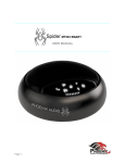
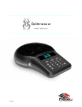
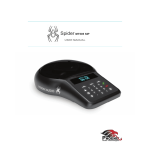
Spider MT503 SMART
USER MANUAL
Page 1
INDEX
Overview
.....................................................Page 03
Connecting the Spider
.....................................................Page 04
Using the Spider
.....................................................Page 05
External Mic/Speaker
.....................................................Page 06
Daisy Chaining
.....................................................Page 07
Specifications
.....................................................Page 10
Warranty
.....................................................Page 11
Page 2
SPIDER 503 SMART OVERVIEW
The Spider is a high-quality conference speakerphone that will turn any room into a
professionally sounding conference room. It has an exceptionally large pickup and broadcasting
range, yet is small in size and discreet in design.
The Spider utilizes multiple microphones, a uniquely designed speaker, and a powerful DSP to
achieve commanding performance.
This guide will help you learn how to use your conference phone and will reveal all the features
that come with it.
Page 3
CONNECTING YOUR SPIDER
CONNECTING TO A COMPUTER
This connection is for any session using your computer, such as Voice over IP applications
(Skype, Vidyo, etc.).
‣
Using the USB cable provided, plug the micro USB side of the cable into the Spider
(USB connector located on the connector panel below the unit).
‣
Plug the USB end of the cable into any USB port on your computer, your Spider is ready
for use.
Page 4
No additional drivers or steps are needed. However, we do recommend downloading and using
our “Phoenix Audio Setup Utility” for optimal audio control and performance. This utility can be
found on our website: www.phnxaudio.com/downloads/audiosetup/
CONNECTING TO A SMART DEVICE
This connection is for any session using a smart phone, tablet, or any device that requires an
analog audio signal (Smart Phones, Tablets, Video Codec Systems, etc.).
‣
Using the provided audio cable or any custom made cable, plug the 2.5mm 3-pin
connector side into the Spider’s “Audio Out” jack (located on the connector panel below
the unit).
‣
Plug the other end of the provided cable (3.5mm 4pin connector) into your smart phone
or tablet’s headphone/headset jack.
‣
If applicable, make sure to select the use of the “headset” on your device.
‣
Connect your Spider to a power source using either a USB connection (computer or the
provided 5V USB power supply) or a 48V Daisy Chain Kit power supply. Your Spider is
now ready for use.
USING THE SPIDER
VOLUME
Adjust the volume levels for the Spider’s different volume profiles listed below:
SPEAKER
Change the speaker volume by using
to increase, or
to decrease the volume.
MICROPHONE
Change the microphone sensitivity by using
to increase, or
to decrease the sensitivity.
NOTE: If the sensitivity is set too low you won’t be heard by the far-end. However, if the
sensitivity is set too high, the far-end might get a distorted signal.
MICROPHONE MUTE
In order to mute the Spider’s microphones during a call, press the
button located on the
bottom right of the keypad. When muted, a MUTE symbol will appear on the screen and all the
grill lights will flash red.
To UNMUTE, just press the
Page 5
button again.
HEADSET AND PRIVACY MODE
The Spider allows you to conduct a private conversation using a headset or handset. To use this
feature, just plug in any privacy accessory with a 3.5mm connector (standard stereo headset
jack) into the unit’s External Mic/Spkr connector.
There is no need to unplug the privacy device from the product in order to use the
speakerphone as you can use the toggle button on a headset to switch between the Spider’s
microphone and speaker and the handset’s microphone and speakers. When in privacy mode
the two front LED lights will flash red and blue.
EXTERNAL MIC/SPEAKER
MICROPHONE ONLY
Connect the external microphone to the 3.5mm connector. Select MIC ONLY in the Audio Setup
Utility. (Microphone goes to tip.)
SPEAKERS ONLY
Connect the external speakers to the 3.5mm connector. Select SPEAKERS ONLY in the Audio
Setup Utility. (Speakers go to ring.)
MICROPHONE AND SPEAKERS
Connect the microphone to tip. Split two speakers to ring. Select both MIC and SPEAKERS in
the Audio Setup Utility.
Page 6
DAISY CHAINING
Every Spider comes with the built-in ability to connect to other SMART Spiders (MT503) or
Quattro3s (up to 15 units). This feature enables you to provide coverage for larger spaces using
a chain of units.
NOTE: The Smart Spider (MT503) can act both as master unit as well as a satellite unit.
Page 7
MAKING THE CONNECTION
Choose which unit you would like to act as the master device. This unit will be the one
interfacing for the entire chain. The master unit will be the only unit communicating with an
external device, while all other units will connect and communicate only with each other.
While the SIP (MT505) and PSTN (MT502) Spiders can only act as master units, the Smart
(MT503) Spider can be both a master unit as well as a satellite device.
‣
Using either the provided daisy chain cable or any other Ethernet cable, connect one of
the cable ends to the master unit’s daisy chain DOWN connector (the RJ45 connector
marked “Link Down”).
‣
Take the other end of the cable and connect it to the next unit’s daisy chain UP
connector (the RJ45 connector marked “UP” or “Link Up”).
‣
Repeat the process in order to connect a third unit to unit number 2. This process can be
repeated with up to 15 units regardless of their interface type.
‣
All units in the chain must be Quattro3’s or Spiders and must be powered.
POWERING THE DAISY CHAIN
Every unit in the chain must be powered. In order to do this, there are two available options:
OPTION 1
Power each unit separately, using its own provided USB cable, DC power supply, or internal
battery (if applicable).
OPTION 2
Power only the master unit using the “Daisy Chain Power Kit” (MT320), or the included 48V
power supply. This setup will require you to connect only the first unit to a power source, and will
allow the rest of the units to feed off the master unit via the Ethernet daisy chain cables.
NOTE: While any Spider or Quattro3 can be daisy chained (regardless of interface), the power
daisy chain method requires all units in the chain to have some type of secondary interface card
(ONLY Quattro3 MT301 will not work). The power daisy chain method will work with up to 8
consecutive units before requiring another power source. The power source can be placed
anywhere in the chain (first, last, or middle units).
Page 8
GRILL LIGHTS
When using the device, blue LED lights located under the grill will show the direction of the
Spider’s Beamforming mechanism. This indicates to the user which direction the Spider is
“listening” to. These same lights will blink red when the device’s microphone is muted.
In order to disable the grill light function, press and hold both the on-hook logo AND off-hook
logo for three second.
To enable the feature, just repeat the process.
Page 9
SPECIFICATIONS
• UBS interface (micro B connector)
• 3.5mm external loudspeaker and microphone jack
• Daisy chain expandability of up to 15 units
• Three-way bridging capability
• Frequency response 50Hz – 16KHz
• Low latency (10ms)
• Broadcast level (peak): 92dB SPL @1m (5 watts RMS)
• Noise cancellation > 10dB (without pumping noise)
• 100% full duplex – no attenuation (in either direction) during full duplex
• High-end performance conforms to ITU-T G.167
• Acoustic echo cancellation > 40dB with conversion speed of 40dB/sec
• Residual echo is suppressed to the environment noise level, preventing artificial ducking of signal
• 4 high-quality directional microphones
• Direction-finding algorithm (determines the presence and direction of a speaker)
• Beam-forming algorithm (forms and directs audio beams towards a defined direction)
• Automatic voice-level adjustment (AGC)
• Line-echo canceler active when telephone interface is present
• Metal case and metal grill mesh for high RFI immunity and product durability
Dimensions:
Length: 7” Width: 7” Height: 2.75”
Weight:
2.15 lbs.
Power Consumption:
5V 500mA through USB or wall mount ac/dc adaptor
Software:
Plug- and -Play. No installation or drivers.
Note: Audio Setup Utility is available for Windows. The setup utility helps
monitor the audio input and output level but is not required.
Operating Systems:
Windows 98 and up / Linux / MacOS.
Complies with FCC 47 CFR Part 68, and ACTA adopted technical criteria: TIA-968-A
Complies with FCC 47CFR Part 15; ICES-003: 2004 Issue 4, Class B; AS/NZS CISPR 22: 2006, Class B; EN
55022: 1998+A1(00)+A2(03), Class B;, EN61000-3-2: 2000+A2(05); EN61000-3-3: 1995+A2(05); EN55024:
1998+A1(01)+A2(03)
Complies with ETSI EG 201 121 V1.1.3 (2000-02); ETSI ES 203 021-2 V2.1.2 (2006-01); ETSI ES 203 021-3
V2.1.2 (2006-01)
Conforms to the requirement of the European Union Directive 2002/95EC (RoHS Directive)
Page 10
WARRANTY
The following warranty statement is effective for all Phoenix Audio Technologies’ products as of October 1st,
2007
Phoenix Audio Technologies warrants that this product is free of defects in both materials and workmanship. Should
any part of this product be defective, the Manufacturer agrees, at its option, to repair or replace with a like new
replacement any defective part(s) free of charge (except transportation charges) for a period of two years for all
products. This warranty period begins on the date the end user is invoiced for the product, provided the end user
provides proof of purchase that the product is still within the warranty period and returns the product within the
warranty period to Phoenix Audio Technologies or an authorized Phoenix Audio Technologies dealer according to the
Product Return and Repair Policy listed below. All inbound shipping costs are the responsibility of the end user,
Phoenix Audio Technologies will be responsible for all outbound shipping costs.
Product Return and Repair Policy
1. Return to seller if purchased through an authorized dealer
a.Proof of purchase date from reseller within warranty period must be provided by the end user
b.Seller may, at its discretion, provide an immediate exchange or repair or may return the unit to the
Manufacturer for repair
2. Return to Manufacturer
a. An RMA (return merchandise authorization) number must be obtained by the end user from Phoenix Audio
Technologies
b. The end user must return the product to Phoenix Audio Technologies with proof of purchase (showing
purchase date) for a warranty claim, and display the RMA number on the outside of the shipping package
THIS WARRANTY IS VOID IF:
The product has been damaged by negligence, accident, act of God, or mishandling, or has not been operated in
accordance with the procedures described in the operating and technical instructions; or; The product has been
altered or repaired by other than the Manufacturer or an authorized service representative of the Manufacturer; or;
Adaptations or accessories other than those manufactured or provided by the Manufacturer have been made or
attached to the product which, in the determination of the Manufacturer, shall have affected the performance, safety
or reliability of the product; or; The product’s original serial number has been modified or removed.
NO OTHER WARRANTY, EXPRESS OR IMPLIED, INCLUDING WARRANTIES OF MERCHANTABILITY OR
FITNESS FOR ANY PARTICULAR USE, APPLIES TO THE PRODUCT. MANUFACTURER’S MAXIMUM LIABILITY
HEREUNDER SHALL BE THE AMOUNT PAID BY THE END USER FOR THE PRODUCT.
Manufacturer shall not be liable for punitive, consequential, or incidental damages, expenses, or loss of revenue or
property, inconvenience, or interruption in operation experienced by the end user due to a malfunction in the
purchased product. No warranty service performed on any product shall extend the applicable warranty period. This
warranty extends only to the original end user and is not assignable or transferable. This warranty is governed by the
laws of the State of California.
For more information or technical support please
refer to our website www.phnxaudio.com,
email us at [email protected],
or call (818) 937-4779
Phoenix Audio Technologies, 16 Goodyear #120, Irvine, CA 92612 Telephone: (818) 937-4774, Fax:
818-859-1054, [email protected]
Page 11