1
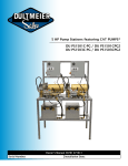
A World Leader in Diaphragm Pumps
Operating and Maintenance Manual
Thank you for purchasing a Comet Pump. Comet is an ISO 9001 manufacturer and as such produces quality products which are safe, efficient and durable. Please read this manual carefully paying great attention to all the information provided especially that on safety issues.
The following data is on the pump name plate:
1. Pump Model
2. Maximum delivery ( at 0 psi)
3. Flow rate at maximum pressure
4. Maximum in pump pressure
5. Max R.P.M.
6. Serial number
www.cometpumps.com
Toll Free (800) 331-7727
OPERATING INSTRUCTIONS
Preliminary Maintenance
A) Check oil level, when pump is idle and placed horizontally, it must be at the mark indicated on the oil site
glass (fig. 1) or be visible on the oil level plug (fig. 2), depending on type of pump. Top off with SAE 30W nondetergent oil if necessary.
B) Check the air pressure in the pressure accumulator if applicable, (fig. 3) depending on the range of pressure
used in the pump. Pressurize according to table A. The pressure may be checked and changed accordingly
using an air pump.
TAB. A
Pressure
accumulator (psi)
Pressure of pumps
(psi)
When in use
30
30-75
30-75
75-150
75-105
150-300
105
300-750
ATTENTION: before staring the pump, make sure that taps not in use are in
the “closed” position (fig. 4).
ATTENTION: Make sure that the moving parts of the pump are properly protected and are not accessible to other persons not authorized.
NOTICE: if the machine is used at a very low temperature, make sure there
is no ice inside the pump and manifolds, turning the eccentric shaft of the
pump by hand, after disconnecting it from the tractor.
NOTICE: Avoid exposing pump to freezing temperatures. If this is unavoidable run antifreeze through pump for several minutes then purge system of
any antifreeze before use.
STARTING
a) Follow the pump Manual instructions.
b) The pump must turn at a rotation speed between 400 - 550 rpm.
c) To prime pump quickly, keep the suction circuit at “0” pressure or near to “0”. Repeat this operation each
time the pump is emptied.
d) Bring the pump to the rated pressure according to the type of work to be carried out by regulating the
pressure of the control. The pressure must not exceed the maximum pressure of the pump.
e) Monitor the oil level during the first few hours of operation and add oil (when pump is idle) if necessary.
MAINTENANCE
Wash the pump after use by running clean water through it for a few minutes.
Periodical maintenance to be carried out by user as follows:
ATTENTION: check pump only when it is not running.
OIL
The level and cleanliness of the oil should be frequently checked (eg: each time the tank is filled). This will indicate if the
pump and diaphragm are working properly.
OIL LEVEL
When pump is turned off, the oil level must correspond to the reference slot found on the oil sight glass or oil level cap
depending on type of pump. The oil level is not always constant when the diaphragm pump is working: the oil level is
lowered when the pump starts working and is priming, when the spray liquid reaches the pump, the oil level rises to normal level.
During operation attention must be made to a decrease in the oil level:
a) if this happens during the first hours of working it is normal. Add SAE 30W non-detergent type oil to proper level as in
fig.5.
b) if this happens after many hours of work and continues after 1 or 2 top ups, it is a symptom of diaphragm swelling
caused by suction vacuum (dirty filter, deformed inlet tube or chemical attack to diaphragm). In this case check the
filter and inlet system and/or refer to a specialized technician to check the diaphragm.
STATE OF OIL IN THE CASE OF BROKEN DIAPHRAGM
If the oil becomes white (water present in oil), it may be a symptom of breakage of one or more diaphragms, therefore it
is necessary to stop work and let a specialized technician check the conditions of the diaphragm and substitute if necessary.
Notice:
• If work is continued during these conditions it may cause serious damage to internal parts of the pump.
• If it is not possible to substitute the diaphragm within one day of its breakage, empty the crankcase of water and pour in oil (even
used) or diesel oil to stop rust from forming on the internal components .
INLET SYSTEM
The inlet system must be kept efficient, that is:
There must not be:
• Entrance of air caused by tube wear;
• Loosening of fittings;
• Wear of joints;
Regarding this, check that there are no small drips when the pump is still, this means air is entering the pump when in
motion.
The filter must be maintained and kept clean with frequent inspections especially if powder based products are used.
PUMP MOUNTING
ATTENTION: periodically check, especially when there is vibration during use (chain tractors, gasoline/diesel engines) that the mounting screws on the machine frame are tightened and if necessary re-tighten according to the machine manufacturer instructions.
PRESSURE ACCUMULATOR
Check pressure in pulsation dampner, if present, and for pulsation on the pressure gauge.
EXTRA MAINTENANCE
The following maintenance operations must be carried out periodically by a specialized technician.
OIL REPLACEMENT
It is advised to replace the oil after the first 300 hours of work and then every time the diaphragm is changed.
ATTENTION: The oil must be collected in the proper containers and not thrown into the environment.
DIAPHRAGM REPLACEMENT
At the end of every season it is advised to check the diaphragms and replace them if worn or distorted . If particularly
strong chemical products are used, it is recommended to replace the diaphragms every year regardless of their condition.
INLET AND DELIVERY VALVES
Periodically check (every 300 hours under normal working conditions) the state of the inlet and delivery valves. The
maintenance must be more frequent if sandy liquid or abrasive liquids are used. It must also be carried out if drops or
changes of pressure, irregular functioning and strange noises are noticed.
OPERATION
CHECK STATE AND LEVEL OF OIL
Every 8h
X
Maintenance Intervals
Every 50h
Every 300h
CHECK PRESSURE ACCUMULATOR
X
CHECK INTAKE (TUBES & FITTINGS)
X
CHECK AND CLEAN THE INLET FILTER
CHECK FIXING OF PUMP MOUNTING
X
X
CHECK DIAPHRAGM AND POSSIBLE SUBSTITUTE
CHANGE OIL
CHECK INLET/DISCHARGE VALVES
CHECK TIGHTENING OF PUMP SCREWS
Note: X operation to be carried out by the operator
0 operation to be carried out by specialized technician
(1) first oil change
(2) change to be carried out same as diaphragm change
End of season
0
0 (1)
0
0 (2)
0
TROUBLE SHOOTING
SYMPTOM
The pump does not charge
CAUSE
REMEDY
Air inlet
Regulation valve closed control group not at
zero
Valve and/or site of inlet valve and delivery
worn or dirty
Check inlet for blockage
Position the lever
Worn valve and/or site of regulation valve
Valve and/or site of inlet valve and delivery
worn or dirty
Insufficient rpm’s.
Worn nozzles used or holes too big
Replace or clean
Replace or clean
Pressure irregular or with pulse Valve and/or site of inlet valve and delivery
worn or dirty
Replace or clean
The pump does not reach the
desired pressure
Replace or clean
Bring the rpm to 350 - 550 rpm
Replace
Air inlet
Check inlet for blockage
Excessive diaphragm vibrations
Pressure accumulator discharged or with incorrect air pressure
Bring air to correct pressure
Noise when oil level is lowered
Blocked inlet
Check inlet for blockage
Water present in oil
Broken diaphragm
Replace.
If replacement is not immediate, empty
water from pump introduce oil without water (even used) or naphtha to stop internal
parts from rusting.
WARRANTY INFORMATION
•
The Manufacturer warrants its products for 12 months from the date of purchase, provided that the below is sent
to the Manufacturer fully filled out and within 10 days from the delivery date.
• In accordance with the above –mentioned terms, the Manufacturer agrees to furnish free of charge any replacement parts for such parts as, in the Manufacturer’s opinion or that of their authorized representative, are defective either in material or manufacture. In any case transport and labor costs shall be charged to the customer.
• The product returned to Comet S.p.A. for warranty inspection or repair must be sent back together with each single part the unit is complete with and must not have been improperly damaged. Comet will otherwise decline all
responsibility for any warranty claims.
• The warranty does not include any payment for faults due to incorrect usage by the operator and for parts falling
within the usual maintenance, such as: Gaskets, diaphragms sealing rings, oil and so on.
• The Manufacturer shall not be held responsible for accidents to the operator or third parties while the equipment
is in use.
• This warranty shall not be valid if:
A) Previous service or repairs were performed by unauthorized individuals or companies.
B) The equipment was previously repaired with non original parts
• Breakdowns and failures in our machines during or after the warranty period, do not grant any right to suspend
payments for the goods delivered which have already been agreed to. Nor can such breakdowns and failures
be used to excuse further delay in such payments
• The Manufacturer reserves the right at any time to carry out any and all changes to improve his products. Nor
shall he be obliged by this to add such improvements to units previously manufactured already consigned or in
the process of installation.
• These general conditions of warranty hereby substitute and nullify every previous condition expressed or implicit.
Common causes of diaphragm failure
Two marks in correspondence to valve seat
TOP
Fatigued and worn underneath piston retaining disc
and two marks in correspondence to valve seat.
Causes
1. Restricted suction.
Blocked suction filter.
Suction hose blocked or
kinked. Suction lift too
high. Spray mixture too
thick (dense)
2. Pump RPM above specification
Causes
1. Chemical incompatible
with diaphragm material
2. Diaphragm swollen and
soft
3. Diaphragm soft and
spongy (Below 60º)
4. Diaphragm profile distorted
5. Diaphragm shape distorted
6. Increase in external diameter
7. Diaphragm swollen
3.
Suction valve not sealing
4. Cylinder Sleeve holes not
in correct position
5.
TOP
Chemical incompatible
with diaphragm material,
in addition to one of the
above causes.
Circular fracture on piston
side of diaphragm that is
same size as piston.
TOP
OIL
Causes
1. Excessive wear between
piston and valve
2. Suction has too much pressure (excessive head)
3. Low pump RPM
4. Cylinder sleeve holes not in
correct position
5. Delivery valve not sealing
6. Low oil level in pump
Fracture on external diameter and worn or fatigued
under piston retaining disc.
TOP
Causes
Fatigue breakage, diaphragm
worn out
Remedy
Diaphragm must be checked
once a year.
BOTTOM
Straight fracture
A. Standard shape
Causes
Incorrect air bleeding, air
trapped under diaphragm
B. Diaphragm distorted
B. Swollen diaphragm
Notes