1
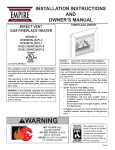
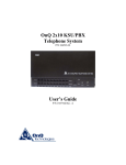
Extract from the online
catalog
IBS S5 DSC/I-T
Discontinued item
Order No.: 2752000
http://eshop.phoenixcontact.de/phoenix/treeViewClick.do?UID=2752000
Termination Boards for Siemens SIMATIC ® S5 PLCs, with electrical
isolation
Commercial data
EAN
4017918120269
Pack
1 pcs.
Customs tariff
85389091
Weight/Piece
0.5427 KG
PHOENIX CONTACT Inc., USA
http://www.phoenixcon.com
http://
www.download.phoenixcontact.com
Please note that the data given
here has been taken from the
online catalog. For comprehensive
information and data, please refer
to the user documentation. The
General Terms and Conditions of
Use apply to Internet downloads.
Page 1 / 6
Oct 22, 2009
IBS S5 DSC/I-T Order No.: 2752000
http://eshop.phoenixcontact.de/phoenix/treeViewClick.do?UID=2752000
Product description
INTERBUS controller boards for Siemens SIMATIC S5 controllersSIMATIC S5-115U through to 155U PLCs can be
connected to INTERBUS by means of the IBS S5 DSC/I-T controller board. The controller board is connected to the
controller via the SIMATIC I/O bus. It functions as a system I/O module with a variable address area so that the data of
the INTERBUS input and output modules can be accessed directly using the periphery (L PW, T PW, ...) or indirectly
using the process image (A I, S Q, ..).The INTERBUS system is activated automatically at power on or through the
application. For this option, a system-specific parameter assignment for the INTERBUS system and controller board
is stored centrally in a pluggable parameterization memory on the controller board.The user-friendly IBS CMD SWT
INTERBUS software for the Windows operating system is available for creating the parameter data. In addition to
parameterization, configuration and system documentation, IBS CMD SWT, as universal software, also makes possible
the diagnostics of individual devices and the entire INTERBUS system. Furthermore, the local status of the connected
INTERBUS devices can be displayed while the system is in operation. The following range of functions supplements
this high-performance controller board:- Process data preprocessing (to IEC-1131)- Synchronous operating modesParameterization of alternative and changing bus segments- Parameterization using CMD- Startup using "Plug & Play"
technologyThe IBS S5 DSC controller board offers a user-oriented LC display for visualizing the extensive INTERBUS
system diagnostic capabilities. Operational and error states are shown on this display in plain text format. The direct
display of messages helps reduce startup and downtimes, increasing the reliability of your systems.
Technical data
Control system
Diagnostics tool
DIAG+ from version 1.0x
Configuration tool
CMD from Version 4.0x
Software requirements
Configuration tool
CMD from Version 4.0x
Diagnostics tool
DIAG+ from version 1.0x
Power supply
Connection supply
Via SIMATIC I/O bus
Typical current consumption
1.5 A
Supply voltage
5 V DC
Range of supply voltages
4.8 V DC ... 5.3 V DC (including ripple)
Residual ripple
2.2 mVPP
General data
Weight
500 g
Format
2 narrow slots
Degree of protection
IP00
Data interfaces
Interface
INTERBUS remote bus
Type of connection
9-pos. D-SUB female connector (optionally optical fiber possible
via interface converters) with electrical isolation
PHOENIX CONTACT Inc., USA
http://www.phoenixcon.com
Page 2 / 6
Oct 22, 2009
IBS S5 DSC/I-T Order No.: 2752000
http://eshop.phoenixcontact.de/phoenix/treeViewClick.do?UID=2752000
Interface
Parameterization/operation/diagnostics
Type of connection
RS-232-C, D-SUB 9-pos. male connector
Interface
Host system
Type of connection
Siemens SIMATIC S5 115U (requires adapter capsule 6E5S 491OLB11) - 155U, 130 WB, 150S
Interrupts
Are supported
INTERBUS data
Type
INTERBUS master
Number of devices with parameter channel (PCP)
max. 62
Number of supported devices
max. 512 (of which 254 are remote bus devices/bus segments)
Certificates / Approvals
Certification
CUL, GOST, UL
CUL
Nominal voltage UN
5V
Nominal current IN
1.5 A
UL
Nominal voltage UN
5V
Nominal current IN
1.5 A
Accessories
Item
Designation
Description
Cable/conductor
2806862
IBS PRG CAB
Connection cable, to connect the controller boards to the PC
(RS-232-C), length 3 m
2762003
PSM-KA-V24/TTY-P/PA/BB
Connection cable, to connect the controller board to the Pg (TTY),
length: 90 cm
IBS MC FLASH 2MB
Program and configuration memory, 2 Mbyte
Memory
2729389
PHOENIX CONTACT Inc., USA
http://www.phoenixcon.com
Page 3 / 6
Oct 22, 2009
IBS S5 DSC/I-T Order No.: 2752000
http://eshop.phoenixcontact.de/phoenix/treeViewClick.do?UID=2752000
Software
2730307
DIAG+
Diag+, diagnostics software, for INTERBUS networks, area of
application: Startup, maintenance and, for example, for integration
in control desk software, can be integrated in 32 bit applications
(ActiveX-capable)
2721439
IBS CMD SWT G4
Network configuration software for INTERBUS Generation 4
2721442
IBS CMD SWT G4 E
Network configuration software for INTERBUS Generation 4
FAQs
•
Additional parameter "Data Consistency" when using the IB DB data block
During parameterization of an IBS S5 DSC/I-T controller board with the IB DB data block, a value must be entered
for data consistency in addition to the parameters described in the manual. If this value is not entered, the following
message is displayed: <0A44hex + module address>. Example, data consistency for eight bit: Entry: KY 128, 070.
The entry 128 indicates that bit 15 is set and therefore that a data consistency of eight bits is ensured.
•
Control system switches to STOP state with an acknowledgment delay when executing FB60 IFSPINI
Check whether the communication register, as a parameter on the FB60 ISFPINI (ADDR: KF +xxx), corresponds
with the preset value of the DIP switches on the controller board. If you have programmed a DB0 or DB1 (depends
on controller type), check that the address of the communication register has not been used there. See also:
INTERBUS User manual, driver software, for controller board for Siemens SIMATIC S5 Order no.: 27 47 73 0
Designation: IBS S5 DSC SWD UM INTERBUS Quickstart, Order no.: 27 47 66 2 Designation: IBS S5 DSC QS UM
•
How can I use the extended I/O area (Q) for the SIMATIC 115U and the IBS S5 DSC controller board?
The expanded I/O area (Q) can be used for PLCs with CPU type 945 if the controller board is in a PLC expansion
rack. The bus in the base rack of the PLC does not allow simultaneous use of the P and Q areas. The expanded I/O
area (Q) cannot be used for 115U PLC series with other types of CPU.
•
How do I set the data consistency?
The data consistency depends on the setting in the CMD software tool and on the operand in STEP 5. 16-bit
consistency: L PW, T PW 32 Bit consistency: L PEW, T PAW The following marginal conditions must be observed:
A consistency range assigns sequential addresses which must be addressed one after another. Access the ranges
in the preset consistency (e.g. 8-bit consistency: byte commands). Data transfer must not be interrupted by alarm
management or interrupts. Data consistency > 32 bits is typically possible, but is not guaranteed. Synchronous
operating mode can be helpful here.
•
Is it possible to implement a bus parameterization with isolated disconnection if an incorrect bus is
connected?
Yes, it is possible. Before a bus start it however is necessary to activate the configuration frame. Activate
configuration frame: Code: 0711 Parameter_Count: 0001 Frame_Reference: 0001 Start bus: Code: 0701
•
Message 0946hex in the display of the controller board after writing the parameterization memory
The write protection of the parameterization memory is activated. Deactivate the write protection of the flash EPROM
of the controller board (parameterization memory). See also: INTERBUS User manual Services and error messages
of the firmware order no.: 27 45 13 0 Designation: IBS SYS FW G4 UM INTERBUS Diagnostics guide G4 Order no.:
27 47 28 0 Designation: IBS SYS DIAG DSC UM
PHOENIX CONTACT Inc., USA
http://www.phoenixcon.com
Page 4 / 6
Oct 22, 2009
IBS S5 DSC/I-T Order No.: 2752000
http://eshop.phoenixcontact.de/phoenix/treeViewClick.do?UID=2752000
•
Message 09D1hex on the controller board display, controller board not in RUN state
The flash EPROM in the controller board was recognized as being faulty. Replace the flash EPROM with a new
one and start the controller board as usual. See also: INTERBUS User manual Services and error messages of the
firmware order no.: 27 45 13 0 Designation: IBS SYS FW G4 UM INTERBUS Diagnostics guide G4 Order no.: 27 47
28 0 Designation: IBS SYS DIAG DSC UM
•
New MC flash memory cards
From firmware 4.35 there are 2 MB and 4 MB memory cards for all G4 controllers with PCMCIA slot: 27 29 38 9 IBS
MC FLASH 2 MB 27 29 39 2 IBS MC FLASH 4 MB.
•
The PLC does not start when using the IBS S5 DSC controller board in a SIMATIC.
Another device in the PLC (multiprocessor coordinator, intelligent modules, PCs) has assigned I/O addresses in
the preset communication register PW252 on the IBS S5 DSC controller board. This means that addresses are
assigned twice. Change the address of the communication register on the controller board as well as on the starting
module ISFPINI FB60. If you have configured the bus using the CMD software from Phoenix Contact, you must also
enter the new address for the communication register. Please make sure that all other registers (diagnostic register,
control register) are modified correspondingly. IMPORTANT: The changed communication register should lie outside
the process image (PW0-PW127), otherwise services which are issued to the controller board using a function block
may not be executed or may be executed incorrectly.
•
The services which were issued from the PLC to the controller board using a function block, are not
executed or executed incorrectly.
A possible cause is that the selected address for the communication register is in the area of the process image.
Please make sure that the communication register is outside the process image (from PW128).
•
Why do I need a function block (FB60, ISFPINI) in the PLC to start the INTERBUS interface?
The ISFPINI function block synchronizes the PLC with the controller board. The idea is to keep the PLC in the
starting mode until the controller board indicates that it is ready for operation. See also: INTERBUS User manual,
driver software, for controller board for Siemens SIMATIC S5 Order no.: 27 47 73 0 Designation: IBS S5 DSC SWD
UM
PHOENIX CONTACT Inc., USA
http://www.phoenixcon.com
Page 5 / 6
Oct 22, 2009
IBS S5 DSC/I-T Order No.: 2752000
http://eshop.phoenixcontact.de/phoenix/treeViewClick.do?UID=2752000
Address
PHOENIX CONTACT Inc., USA
586 Fulling Mill Road
Middletown, PA 17057,USA
Phone (800) 888-7388
Fax (717) 944-1625
http://www.phoenixcon.com
© 2009 Phoenix Contact
Technical modifications reserved;
PHOENIX CONTACT Inc., USA
http://www.phoenixcon.com
Page 6 / 6
Oct 22, 2009