1
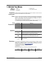
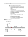
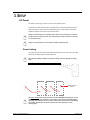
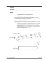
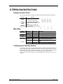
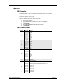
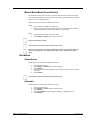
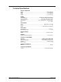
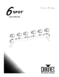
User Manual TABLE OF CONTENTS 1. BEFORE YOU BEGIN.............................................................................................................................................................................3 SAFETY INSTRUCTIONS.................................................................................................................................................................................. 4 2. INTRODUCTION .....................................................................................................................................................................................4 PRODUCT OVERVIEW .................................................................................................................................................................................... 4 3. SETUP .....................................................................................................................................................................................................5 AC POWER ................................................................................................................................................................................................. 5 Power Linking ................................................................................................................................................................................................................. 5 MOUNTING .................................................................................................................................................................................................. 6 Orientation ..................................................................................................................................................................................................................... 6 Rigging........................................................................................................................................................................................................................... 6 4. OPERATING INSTRUCTIONS ...............................................................................................................................................................7 USING THE CONTROL PANEL .......................................................................................................................................................................... 7 MENU MAP.................................................................................................................................................................................................. 7 CONFIGURING THE STARTING ADDRESS ........................................................................................................................................................... 7 OPERATION ................................................................................................................................................................................................. 8 DMX Operation ............................................................................................................................................................................................................... 8 DMX Channel Values...................................................................................................................................................................................................... 8 Master/Slave Mode (Sound-Active) ................................................................................................................................................................................. 9 STANDALONE ............................................................................................................................................................................................... 9 Sound-Active .................................................................................................................................................................................................................. 9 Automatic ....................................................................................................................................................................................................................... 9 5. TECHNICAL INFORMATION ...............................................................................................................................................................10 TECHNICAL SPECIFICATIONS ..............................................................................................................................................................11 6Spot™ User Manual (Rev. 2) Page 2 of 12 1. BEFORE YOU BEGIN What Is Included • • • • • 6Spot™ Power Cord Mounting Kit Warranty Card Quick Reference Guide Unpacking Instructions Carefully unpack the product immediately and check the container to make sure all the parts are in the package and are in good condition. Claims If the box or the contents (the product and included accessories) appear damaged from shipping, or show signs of mishandling, notify the carrier immediately, not CHAUVET®. Failure to report damage to the carrier immediately may invalidate your claim. In addition, keep the box and contents for inspection. For other issues, such as missing components or parts, damage not related to shipping, or concealed damage, file a claim with CHAUVET® within 7 days of delivery. Text Conventions Symbols Convention 1~512 50/60 Settings <ENTER> ON Meaning A range of values A set of values of which only one can be chosen A menu option not to be modified A key to be pressed on the product’s control panel A value to be entered or selected Symbol Meaning Critical installation, configuration, or operation information. Not following these instructions may make the product not work, cause damage to the product, or cause harm to the operator. Important installation or configuration information. The product may not function correctly if this information is not used. Useful information. Disclaimer 6Spot™ User Manual (Rev. 2) The information and specifications contained in this User Manual are subject to change without notice. CHAUVET® assumes no responsibility or liability for any errors or omissions, and reserves the right to revise or recreate this manual at any time. Download the latest version from www.chauvetlighting.com. © Copyright 2013 CHAUVET®. All rights reserved. Printed in P.R.C. Electronically published by CHAUVET® in the United States of America. Author Date Editor Updated A. Chiappone 1/10/11 S. Diaz 1/31/13 Page 3 of 12 Safety Instructions Please read these instructions carefully. It includes important information about the installation, usage and maintenance of this product. • • • • • • • • • • • • • • Please keep this User Manual for future consultation. If you sell the unit to another user, be sure that they also receive this instruction booklet. Always make sure that you are connecting to the proper voltage, and that the line voltage you are connecting to is not higher than that stated on the decal or rear panel of the fixture. This product is intended for indoor use only!To prevent risk of fire or shock, do not expose fixture to rain or moisture. Make sure there are no flammable materials close to the unit while operating. The unit must be installed in a location with adequate ventilation, at least 20in (50cm) from adjacent surfaces. Be sure that no ventilation slots are blocked. Always disconnect from power source before servicing or replacing fuse and be sure to replace with same fuse source. Secure fixture to fastening device using a safety chain. Maximum ambient temperature (Ta) is 104°F (40°C). Do not operate fixture at temperatures higher than this. In the event of a serious operating problem, stop using the unit immediately. Never try to repair the unit by yourself. Repairs carried out by unskilled people can lead to damage or malfunction. Please contact the nearest authorized technical assistance center. Never connect the device to a dimmer pack. Make sure the power cord is never crimped or damaged. Never disconnect the power cord by pulling or tugging on the cord. Never carry the fixture directly from the cord. Always use the hanging/mounting bracket. Avoid direct eye exposure to the light source while it is on. 2. INTRODUCTION Product Overview Microphone Control Panel (LED Display) DMX Out DMX In Microphone Adjustment Tripod Stand Fastening Knob 6Spot™ User Manual (Rev. 2) Power In Back Panel Fuseholder Power Out Page 4 of 12 3. SETUP AC Power This fixture is auto-ranging and runs on 100~240 VAC, 50/60 Hz power. To determine the power requirements for a particular fixture, see the label affixed to the back plate of the fixture or refer to the fixture’s specifications chart. A fixture’s listed current rating indicates its average current draw under normal conditions. Always connect the fixture to a switched circuit. Never connect the fixture to a rheostat (variable resistor) or dimmer circuit, even if the rheostat or dimmer channel is used only as a 0 to 100% switch. Always connect the fixture to a circuit with a suitable electrical ground. Power Linking This fixture contains power linking via the Edison outlet located in front of the power input cable. Please see the diagram below for further explanation. The maximum quantity of 6SPOT™s that may be linked is 18 units @ 120V, 33 units @ 230V Fixture #1 Fixture #2 Fixture #3 Additional power link out The power linking shown in this document is for the CHAUVET® North American version ONLY! Therefore, it is the customer’s responsibility to check with the Dealer/Distributor regarding power linking on the local version of the product. Connections and availability may change, depending on the power requirements and/or regulations of each country/region. 6Spot™ User Manual (Rev. 2) Page 5 of 12 Mounting Orientation The 6SPOT™ may be mounted in any position, provided there is adequate room for ventilation. Rigging This fixture has multiple rigging options. They are as follows: Floor Standing (using the two mounting/standing brackets) Hanging (using the two mounting/standing brackets) Hanging (using the two hanging clamp Mounting points) Be sure that the structure can support the weight of the fixture. Please see the “Technical Specifications” section of this manual for a detailed weight listing. Mount the fixture securely. This may be done with a screw, nut and bolt, or a mounting clamp. The hole in each bracket is 13 mm in diameter. When rigging, consider routine maintenance and control panel access. Please see the following notes on installation. • • • If the power link out is intended to be used with multiple fixtures, take into account the length of each power cable, and mount the fixtures close enough to one another to accommodate for this. When aiming the fixtures, use the bracket/yoke adjustment knobs. Loosen the knobs, adjust to the desired angle, and then tighten the knobs by turning them clockwise. Do not use tools for this step, as it may cause damage. Safety cables must always be used! Pod Adjustment Knob Fixture Adjustment Knob (2) Hanging Clamp Mounting Point (2) Mounting/Standing Bracket (2) 6Spot™ User Manual (Rev. 2) Page 6 of 12 4. OPERATING INSTRUCTIONS Using the Control Panel Access control panel functions using the four buttons located directly underneath the LED display. BUTTON <MODE> <UP> <DOWN> <ENTER> FUNCTION Used to scroll through the current operating mode, as well as back out of the current menu option Used to select a increasing value Used to select an decreasing value Used to activate a selection and store it to memory Menu Map Mode DMX Mode Slave Operation Invert Sound-active Selection 1 Addr Selection 2 d001~d512 SLAU Slave HNo~YES SoUd rUn PAutomatic Description DMX Operation Select the DMX starting address P-_1~10 S 01~S100 Invert the operation (pod 1 becomes pod 6) Select YES to activate this function Trigger the built-in program to the beat of the music, using the internal microphone Trigger the built-in programs with variable speed Select one of the built-in programs Adjust the speed of the automatic program Configuring the Starting Address The 6SPOT™ fixture uses up to eight DMX channels.In this DMX configuration/personality, the highest configurable address is 505. Any address higher than this will prevent access to all of the channels while in this mode; however, if you desire to use one of the other DMX configurations (personalities), please consider the total DMX channels when selecting a DMX address. If this is your first time using DMX, we recommendreading the “DMX Primer” section in the “Appendix”. 6Spot™ User Manual (Rev. 2) Page 7 of 12 Operation DMX Operation This operating mode will allow for control with an external DMX controller. You must set the starting address for this mode. If this is your first time using DMX, then it is recommended that you refer to the “DMX Primer” section in the “Appendix” of this manual. Please see the instructions below for details on this mode. 1. 2. 3. 4. 5. 6. Plug the fixture into power. Plug a DMX controller into the fixture in a daisy chain configuration. Press <MODE> until Addr appears on the LED screen. Press <ENTER>. Using <UP>&<DOWN>, select the DMX starting address. Press <ENTER>. DMX Channel Values CHANNEL VALUE FUNCTION 1 000 010 011 045 046 080 081 115 116 150 151 185 186 220 221255 Pod 1 Blackout Red Green Blue Yellow Magenta Cyan White 2 000 010 011 045 046 080 081 115 116 150 151 185 186 220 221255 Pod 2 (run speed when CH.8 is between 011~239) Blackout Red Green Blue Yellow Magenta Cyan White 3~6 000 010 011 045 046 080 081 115 116 150 151 185 186 220 221255 Pod 3~6 Blackout Red Green Blue Yellow Magenta Cyan White 000009 010255 Strobe No function Strobe (slow~fast) 000010 011047 048095 096119 120144 145167 168191 192215 216239 240255 Mode Individual pod control with strobing (channels 1~7) Automatic 1 Automatic 2 Automatic 3 Automatic 4 Automatic 5 Automatic 6 Automatic 7 Automatic 8 Sound-active 7 8 6Spot™ User Manual (Rev. 2) Page 8 of 12 Master/Slave Mode (Sound-Active) This mode allows a single unit, the master, to operate in either automatic or sound-active mode. When additional (slave) fixtures are daisy chained to the master, they will all synchronize with the master and run the same lighting show. Please see the instructions below for details on this mode. Master: 1. 2. Slave: 1. 2. Place the master fixture first in the daisy chain. Set the master fixture to operate in either automatic or sound-active mode; please see the appropriate sections of this manual for details on this procedure. Daisy chain from the output of the master fixture. Press <MODE> until SLAU appears on the LED screen. Plug the master fixture in LAST! Only connect 31 slave fixtures when operating in this mode! Using the “Invert” function will invert any fixture(s) it is active on. This is useful when you desire to have symmetry to your lighting show. Please see the “Menu Map” for further details. Standalone Sound-Active Please see the instructions below for details on this mode. 1. 2. 3. 4. 5. Plug the fixture into power. Press <MODE> until SoUd appears on the LED screen. Press <ENTER>. Use the microphone sensitivity adjustment knob to adjust the fixture to react to the beat of the music. Press <ENTER>. The microphone will only respond to low frequencies (bass). Automatic Please see the instructions below for details on this mode. 1. 2. 3. 4. 5. 6Spot™ User Manual (Rev. 2) Plug the fixture into power. Press <MODE> until AUTO appears on the LED screen. Press <ENTER>. Using <UP>&<DOWN>, adjust the program speed (S_ _1~S100) (fast~slow). Press <ENTER>. Page 9 of 12 5. TECHNICAL INFORMATION Product Maintenance Dust build-up reduces light output performance and can cause overheating. This can lead to reduction of the light source’s life and/or mechanical wear. To maintain optimum performance and minimize wear, clean the product at least twice a month. However, usage and environmental conditions contribute to increased cleaning frequency. To clean the product, follow the instructions below: • Unplug the product from power. • Wait until the product is cold. • Use a vacuum (or dry compressed air) and a soft brush to remove dust collected on the external surface and reachable internal components. • Clean all external optics and glass/transparent surfaces with a mild soap solution, ammonia-free glass cleaner, or isopropyl alcohol. • Apply the solution directly to a soft, lint-free cotton cloth or a lens cleaning tissue. • Softly wipe any dirt or grime to the outside edges of the external optics or transparent surface. • Gently polish the external optics and transparent surfaces until they are free of haze and lint. Always dry the external optics and transparent surfaces carefully after cleaning them. 6Spot™ User Manual (Rev. 2) Page 10 of 12 Technical Specifications WEIGHT & DIMENSIONS Length ..............................................................................................................35.5 in (902 mm) Width .................................................................................................................... 2.2 in (56 mm) Height ................................................................................................................. 6.5 in (165 mm) Weight ............................................................................................................... 10.1 lbs (4.6 kg) POWER Input voltage ............................................................... 100~240 VAC, 50/60 Hz (auto-ranging) Power and current ................................................................ 52 W; 0.43 A max (120 V, 60 Hz) Power consumption .............................................................. 57 W; 0.25 A max (230 V, 50 Hz) Power linking ............................................................ max 18 units @ 120 V; 33 units @ 230 V Fuse ........................................................................................................................ F 1 A, 250 V LIGHT SOURCE Type ....................................................................................................high-power, tri-color LED Quantity......................................................................................................................................6 Rating .......................................................................................... (3 W) 375 mA x 3; 50,000 hrs PHOTO OPTIC Lux (per light) .............................................................................................................814 @ 1 m Beam angle (per light) ........................................................................................................... 11° INDOOR/OUTDOOR Rating ........................................................................................................... For indoor use only THERMAL Maximum ambient temperature .......................................................................... 104° F (40° C) CONTROL & PROGRAMMING Data input .................................................................................. locking 3-pin XLR male socket Data output ............................................................................. locking 3-pin XLR female socket Data pin configuration ................................................................ pin 1 shield, pin 2 (-), pin 3 (+) Protocols ........................................................................................................... DMX-512 USITT DMX Channels .......................................................................................................................... 8 ORDERING INFORMATION 6SPOT™ .........................................................................................................................6SPOT WARRANTY INFORMATION Warranty ................................................................................................ 2-year limited warranty 6Spot™ User Manual (Rev. 2) Page 11 of 12 To return a product or request support: In the U.S., contact CHAUVET® World Headquarters (see below). In the UK or Ireland, contact CHAUVET® Europe Ltd. (see below). In any other country, DO NOT contact CHAUVET®. Contact your distributor. See www.chauvetlighting.com for distributors outside the U.S., United Kingdom, or Ireland. If you live outside the U.S., United Kingdom, or Ireland, contact your distributor of record and follow their instructions on how to return CHAUVET® products to them. Visit our website for contact details. Returns Call the corresponding CHAUVET® Technical Support office and request a Return Merchandise Authorization (RMA) number before shipping the product. Be prepared to provide the model number, serial number, and a brief description of the cause for the return. You must send the merchandise prepaid, in its original box, and with its original packing and accessories. CHAUVET® will not issue call tags. Clearly label the package with the RMA number. CHAUVET® will refuse any product returned without an RMA number. Write the RMA number on a properly affixed label. DO NOT write the RMA number directly on the box. Before sending the product, clearly write the following information on a piece of paper and place it inside the box: • Your name • Your address • Your phone number • The RMA number • A brief description of the problem Be sure to pack the product properly. Any shipping damage resulting from inadequate packaging will be your responsibility. FedEx packing or double-boxing are recommended. CHAUVET® reserves the right to use its own discretion to repair or replace returned product(s). Contact Us World Headquarters CHAUVET® General Information Address: 5200 NW 108th Avenue Sunrise, FL 33351 Voice: (954) 577-4455 Fax: (954) 929-5560 Toll free: (800) 762-1084 Technical Support Voice: (954) 577-4455 (Press 4) Fax: (954) 756-8015 Email: [email protected] World Wide Web www.chauvetlighting.com 6Spot™ User Manual (Rev. 2) United Kingdom & Ireland CHAUVET® Europe Ltd. General Information Address: Unit 1C Brookhill Road Industrial Estate Pinxton, Nottingham, UK NG16 6NT Voice: +44 (0)1773 511115 Fax: +44 (0)1773 511110 Technical Support Email: [email protected] World Wide Web www.chauvetlighting.co.uk Page 12 of 12