1
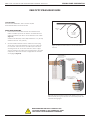
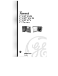
VIRGINIA PANEL CORPORATION
FIBER OPTIC CONTACTS AND MODULES USER’S MANUAL: SECTION 1
FIBER OPTIC RECEIVER CONTACT INSTALLATION AND REMOVAL
TOOLS REQUIRED
0.050” Allen Wrench
Flat Head Screwdriver
Phillips Screwdriver for iCon modules
Mini Fiber Optic Extraction Tool, Part # 910 112 125
CONTACT INSTALLATION INSTRUCTIONS
1.
2.
3.
Remove the dust cap from the VPC contact to be inserted.
Insert the assembled contact into the back (wiring side) of the
assembled module. The contact can only go into one side. Ensure that
the contact is squared up with the corresponding module location.
Once in place, pull the wire slightly to ensure that the contact is
seated.
Figure A. Module Cap Alignment Diagram.
CONTACT REMOVAL INSTRUCTIONS
1.
2.
3.
4.
5.
6.
Remove the module from the receiver frame.
NOTE: For more information concerning the process of removing the
module from the receiver frame, see module installation and removal
instructions in Section 2 of this User’s Manual.
Use the 0.050" Allen wrench to remove the module cap screws located
at the top, middle and bottom of the module (Figure B).
Grasp the module halves and apply force in opposite directions,
rocking the ends of the module slightly while pulling the module cap
away from the mating bottom section. Be sure to open both sides of
the module simultaneously or contacts could be damaged.
Place the Mini Fiber Optic Extraction Tool, part # 910 112 125 (Figure
C), over the contact to be removed/replaced. Use care to keep the
tool perpendicular to the surface of the module, otherwise the tool or
contact could be damaged.
Once the extraction tool is seated and the retaining ring tabs on the
contact are compressed, push the tool into the module. The contact
will be pushed out of the rear of the module.
For 19 and 76 position modules, do not tighten screws. Insert an ITA
contact in positions 2 and 18 or 2A and 18A (for 76 position modules) to
properly align the module cap. With the ITA contacts in place, tighten
the module cap screws. Do not over-tighten screws; screw torque limit
is 13 +/- 1 in-oz.
For all other modules, replace the module cap (Figure A) using both
hands to push the separated halves together. Replace and tighten the
module cap screws to a maximum torque of 2 in-lbs [0.23 Nm].
Figure B. Extraction Tool, Part # 910 112 125.
DO NOT PUSH THE TOOL INTO THE MODULE UNTIL THE TIP
OF THE EXTRACTION TOOL HAS BEEN FULLY SEATED INTO
THE MODULE AND COMPRESSED THE RETAINING RING
TABS ON THE CONTACT.
NOTE: The process shown here uses standard/90 series modules. The same
process is used for modules from other series.
NOTE: If you are using a hybrid module, you may need to reference the
User’s Manual for the other contact type for extraction instructions.
WHEN HANDLING FIBER OPTIC CABLES DO NOT
LOOK INTO THE ENDS OF ANY CONNECTOR. LASER
LIGHT COULD CAUSE PERMANENT EYE DAMAGE.
1-1
Figure C. Be sure to keep the tool perpendicular so as
to avoid bent pins.
For more information, visit vpc.com
4/10/13
VIRGINIA PANEL CORPORATION
FIBER OPTIC CONTACTS AND MODULES USER’S MANUAL: SECTION 1
FIBER OPTIC STRAIN RELIEF GUIDE
TOOLS REQUIRED
Receiver Strain Relief Plate, Part # 510 109 116/298
ITA Strain Relief Plate, Part # 510 109 296
FIBER OPTIC
WIRE
STRAIN RELIEF GUIDELINES
1.
2.
Ensure that the bend radius exceeds the minimum bend
radius of the fiber optic wire at all times. The minimum bend
radius for the fiber optic wire is 15x the diameter of the cable
(Figure A).
Max Bend for 62.5/125µ or 62.5/125µ Multimode: 1.77” [45 mm]
Max Bend for POF: 1.18” [30 mm]
The bend radius minimum must be adhered to when tying
down wires to the strain relief plate. Use two sets of wire ties
for each wire. Take care not to crush fiber optic wire when
cinching the wire tie. For receiver side wires, leave a slight
amount of slack in the cable when securing them to the strain
relief plate to allow the contacts to align when the modules
are engaged (Figure B).
BEND RADIUS
(15x CABLE
DIAMETER)
Figure A. Minimum bend radius is 15x the diameter of
the wire.
USE TWO TIES PER WIRE.
DO NOT CRUSH FIBER OPTIC
CABLES WHEN CINCHING ZIP
TIES FOR STRAIN RELIEF.
A
INNER PORTION OF RECEIVER SIDE
CONTACTS MUST BE FREE TO MOVE
DURING ITA ENGAGEMENT
(DISENGAGED)
DETAIL A
SCALE 3 : 1
INNER PORTION OF RECEIVER SIDE
CONTACTS MUST BE FREE TO MOVE
DURING ITA ENGAGEMENT
(ENGAGED)
DETAIL B
SCALE 3 : 1
Figure B. Use two wire ties for each wire. Make sure to cinch
the ties loosely enough so the wire can move freely when the
modules are engaged.
WHEN HANDLING FIBER OPTIC CABLES DO NOT
LOOK INTO THE ENDS OF ANY CONNECTOR. LASER
LIGHT COULD CAUSE PERMANENT EYE DAMAGE.
1-3
For more information, visit vpc.com
4/10/13