1
User manual
September
2003
Software
XBT-L1000 ver 4.30
Magelis range
Graphic
XBT-F / TXBT-F
WARNING
UNINTENTIONAL EQUIPMENT OPERATION
The application of this product requires expertise in the design and programming of control systems. Only persons with such expertise should
be allowed to program, install, alter, and apply this product.
XBT-L100x V 3.6 and later software should only be used with hardware
dated 98 25 and later.
Failure to follow this instruction can result in death, serious injury,
or equipment damage.
Graphic Magelis
Graphic Magelis
General Contents
Man/machine dialog, application structure, application pages, alarm pages, help
pages, control system, function keys,
PLC/terminal dialog, starter kit.
Introduction
A
Application specifications, development
with XBT-L1000 software, saving the application, transferring the application to
the terminal.
Application Development
With XBT-L1000
B
PLC and terminal communications dialog
principle, dialog tables, dialog cycle.
PLC and Terminal
Communications Dialog
C
Operating the Terminal
D
Application Development
Example
E
Appendices
F
Index
I
Terminal keys and indicator lights, operating principle, page display, entering and
modifying fields, alarms, alarm log, process control, key locking, printing, terminal configuration.
Application specifications, page template
architecture, creating the applications
using XBT-L1000, transferring the application to the terminal, running the application.
XBT Specifications
System messages
Starting up
10 Golden suggestions
Graphic Magelis
M
Graphic Magelis
A
Chapter A
Introduction
Graphic Magelis
A-1
A-2
Graphic Magelis
Contents
This chapter includes the following sections :
1. Man/machine communications dialog using Graphic Magelis terminals ________ 5
Terminals with keyboard ___________________________________________ 5
Touchscreen terminals ____________________________________________ 7
Terminals with touch keys __________________________________________ 9
TXBT Terminals _________________________________________________ 12
2. Structure of the applications ________________________________________ 15
Creating pages _________________________________________________ 17
Pages Types ___________________________________________________ 18
3. Application pages ________________________________________________ 20
Composition of the application pages ________________________________
Accessing the application pages ____________________________________
Displaying the alarm list ___________________________________________
Getting help ____________________________________________________
Recipe pages ___________________________________________________
20
23
24
24
25
4. Alarm pages ____________________________________________________ 26
Alarm indication from an application page _____________________________
Composition of the alarm pages ____________________________________
Advantages of alarm pages ________________________________________
Group of alarms _________________________________________________
26
27
28
29
5. Help pages _____________________________________________________ 30
Application region _______________________________________________
Status line _____________________________________________________
Alarm strip _____________________________________________________
Screen HardcopiesTXBT __________________________________________
30
30
30
30
6. Form pages _____________________________________________________ 31
7. Managing the control system _______________________________________ 32
8. Static and dynamic function keys ____________________________________ 33
Static function keys ______________________________________________ 33
Dynamic function keys ____________________________________________ 33
9. Variable adjustment of the PLC register reference value __________________ 35
TXBT _________________________________________________________ 35
XBT __________________________________________________________ 35
10. PLC/terminal communication dialog _________________________________ 36
Data associated with the fields _____________________________________ 36
Master or client terminal __________________________________________ 37
Graphic Magelis
A-3
A
Server or slave terminal ___________________________________________ 37
Principle of terminal "command and status" exchanges __________________ 37
11. Loading of extension tasks when transferring the application ______________ 39
12. Starter kit for the Graphic Magelis application _________________________ 40
Development hardware kit _________________________________________ 40
Development software kit _________________________________________ 40
Operating hardware kit ___________________________________________ 40
A-4
Graphic Magelis
A
1. Man/machine communications dialog using
Graphic Magelis terminals
Terminals with keyboard
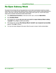
The main functions of the terminals are to:
- Display data from the control system
- Modify the control system parameters
- Control the system using discrete commands.
A
Various terminals are available:
XBT-F 5"
Terminals with LCD screen.
STN Monochrome, 16 gray scale,
320x240 pixels.
10 static function keys.
8 dynamic function keys.
System and
alphanumeric keys.
Downloadable protocols.
Printer output.
XBT-F 10"
Terminals with LCD screen.
STN Monochrome (9.5") or
TFT color (10.4"), 256 colors.
640x480 pixels.
12 static function keys.
10 dynamic function keys.
System and alphanumeric keys.
Downloadable protocols.
Printer output
Graphic Magelis
A-5
1. Man/machine communications dialog using
Graphic Magelis terminals
Display of data from the
control system.
Notification of control
system faults
Dynamic function keys:
- navigating around the various dialog pages,
- controlling the control system
Communication
status indicator
light
Removable
PCMCIA card
including all
information
necessary for
running the
terminal
Key stoke
enabled indicator
light
Static function
keys that can be
used for:
- Operator input to
the control system
- Navigating
between the
various dialog
pages
To record
control system
faults with timestamping
(alarms, groups
of alarms)
Alarms, terminal
references and printout
forms printing
A-6
To modify
control system
Terminal
programming
with XBT-L1000
parameters
Communication with
the control system:
Schneider, Allen Bradley,
Modicon, Omron, Siemens, ...
PLCs
Graphic Magelis
1. Man/machine communications dialog using
Graphic Magelis terminals
Touchscreen terminals
The main functions of the touchscreen terminals are to:
- Display data from the control system,
- Modify the control system parameters,
- Control the system using discrete commands.
A
Various terminals are available:
Touchscreen XBT-F 5"
Resistive matrix touchscreen pad.
6x8 touchscreen zones.
Terminals with LCD screen.
STN color, 256 colors,320x240 pixels.
Downloadable protocols.
Printer output.
Touchscreen XBT-F 10"
Resistive matrix touchscreen
pad.
10x13 touch screen zones.
Terminals with LCD screen.
TFT color, 256 colors,
(10.4" screen)
640x480 pixels.
Downloadable protocols.
Printer output.
Graphic Magelis
A-7
1. Man/machine communications dialog using
Graphic Magelis terminals
Display of data from the
control system.
Notification of control
system faults
Touchscreen zones for:
- navigating around the various dialog pages,
- controlling the control system
Indicator light
communication
control
Removable
PCMCIA card
including all
information
necessary for
running the
terminal
Indicator light
touchscreen
pad pressed
Indicator light
alarm
To record
control system
faults with timestamping
(alarms, groups
of alarms)
Alarms, terminal
references and printout
forms printing
A-8
To modify
control system
Terminal
programming
with XBT-L1000
parameters
Communication with
the control system:
Schneider, Allen Bradley,
Modicon, Omron, Siemens, ...
PLCs
Graphic Magelis
1. Man/machine communications dialog using
Graphic Magelis terminals
Terminals with touch keys
The main functions of the terminals with tactile keys are to:
- Display data from the control system,
- Modify the control system parameters,
- Control the system using discrete commands.
A
Various terminals are available:
Tactile XBT-FC 5"
1 keys row
Resistive matrix tactile pad.
4x8 tactile zones.
4 tactile keys on 1 row at the bottom
of the screen,
Terminals with LCD screen.
STN color, 256 colors, 320*240
pixels.
Downloadable protocols.
Printer output.
Tactile XBT-FC 10"
1 keys row
Resistive matrix tactile pad.
8x13 tactile zones.
8 tactile keys on 1 row at the
bottom of the screen,
Terminals with LCD screen.
TFT color, 256 colors,
(10.4" screen)
640*480 pixels.
Downloadable protocols.
Printer output.
Graphic Magelis
A-9
1. Man/machine communications dialog using
Graphic Magelis terminals
Tactile XBT-FC 10"
2 keys rows
Resistive matrix tactile pad.
6x13 tactile zones.
2x8 tactile keys on 2 rows at the
bottom of the screen,
Terminals with LCD screen.
TFT color, 256 colors,
(10.4" screen),
640*480 pixels.
Downloadable protocols.
Printer output.
Tactile XBT-FC 10"
2 keys columns
Resistive matrix tactile pad.
10x9 tactile zones.
2x6 tactile keys on 2 columns,
Terminals with LCD screen.
TFT color, 256 colors,
(10.4" screen),
640*480 pixels.
Downloadable protocols.
Printer output.
A - 10
Graphic Magelis
1. Man/machine communications dialog using
Graphic Magelis terminals
Display of data from the
control system.
Notification of control
system faults
Touchscreen zones for:
- navigating around the various dialog pages,
- controlling the control system
Indicator light
communication
control
Removable
PCMCIA card
including all
information
necessary for
running the
terminal
Indicator light
tactile pad
pressed
Indicator light
alarm
To record
control system
faults with timestamping
(alarms, groups
of alarms)
To modify control
system
parameters
Terminal
programming
with XBT-L1000
Keys for :
- navigation in the
different pages
- command the
control system
Alarms, terminal references
and printout forms printing
Graphic Magelis
Communication with
the control system:
Schneider, Allen Bradley,
Modicon, Omron, Siemens, ...
PLCs
A - 11
A
1. Man/machine communications dialog using
Graphic Magelis terminals
TXBT Terminals
Terminals with LCD color screen
(640*480 pixels)
(10.4" screen: TXBT-F024)
1.6 Gb hard disk
Windows 95
12 static function keys
10 dynamic function keys
System and alphanumeric keys
Pointing device (except TXBT-F034)
Downloadable protocols
Printer output
External keyboard connection
Slots for 2 ISA bus cards
Application home screen
The functions possible from the home screen (using the dynamic keys)
are:
- Startup of Graphic Magelis applications
- Access to Windows 95
- Closure of home screen
- Setup: terminal parameters setup
For more information refer to the TXBT documentation.
A - 12
Graphic Magelis
1. Man/machine communications dialog using
Graphic Magelis terminals
Display of data from the
control system.
Annunciates control system
faults
Dynamic function keys for:
- operator input to the control system,
- navigating between the various dialog pages
A
Communication
status indicator
light
Removable
PCMCIA card
including all
information
necessary for
running the
terminal
Key stoke
enabled indicator
light
Static function
keys that can be
Tactile pad
used for:
- Operator input to
the control system
- Navigating
between the
various dialog
pages
To record control
system faults with
time-stamping
(alarms, groups
of alarms)
Alarms, terminal references
and printout forms printing
Graphic Magelis
Modifies control system
parameters
Terminal
programming
with XBT-L1000
Communication with the
control system :
Schneider, Allen Bradley,
Modicon, Omron, Siemens, ...
PLCs
A - 13
1. Man/machine communications dialog using
Graphic Magelis terminals
The following application examples may be configured with the Graphic
Magelis:
Production monitoring
Ex.
R1
Automatic operation
R3
Start hydraulic
unit
End of lift
of manipulator
Rotation of grip
to right
R2
R4
R5
R6
R7
R8
Preventive maintenance
R1
R3
Ex.
Counting with indication if
threshold exceeded:
Number of drillings 3137
Tool change at 4000
R2
R4
R5
R6
R7
R8
Process control
R1
R3
Ex.
R5
Commands
Pressurizing : P
Start Cycle : SC
Parameter modification
Level 1 : 556
Limit n12 : 725
R4
R6
R7
A - 14
Graphic Magelis
2. Structure of the applications
An application represents the entire dialog between the user and the
automated process. An application is developed based on the user
requirements:
- User Requirement Control System Interface
- Process control
- Production monitoring
- Preventive maintenance
- ...
- Operator Concerns
- User interface
- Level of involvement
- ...
- Developer Concerns
- Program structure
- Data structure
- Debugging
- Updating
These characteristics determine that your application must be
structured. An application consists of a series of pages, which form a
tree structure as shown in the following example:
Ex.
Automatic operation
R1
Automatic operation
R3
Start hydraulic unit
R5
End of lift of manipulator
The application is organized
into menus and submenus.
Start hydraulic unit
End of lift of manipulator
Graphic Magelis
A - 15
A
2. Structure of the applications
Each page may include the following:
- Static / Dynamic alphanumeric text
- Variable fields used to:
- Display the values indicating control system status (status of
a bit, a single or double word, a floating point word, or an
ASCII string); or
- Enter parameters for operating the control system
(modification of bits, single or double words, floating point
words, or an ASCII string).
The display format can be binary, decimal, hexadecimal, or
alphanumeric.
- Static dynamic graphic objects
- Dynamic function keys objects allowing the user to display other
pages directly, or command the process, or start a Windows 95
application (TXBT).
- A page is identified by a number, and a name (optional).
- Pages may be accessed by pressing the keypad function keys or the
control system.
Pages are called up by :
- pressing a physical function key for terminals with keyboard,
- pressing a "virtual" function key called tactile zone for terminals
with a tactile screen,
- pressing a "virtual" function key called tactile zone or tactile key for
terminals with tactile keys (XBT-FC),
- The arrow keys are used to navigate within a page. Navigation
consists of selecting various input fields.
- Access to pages may be password protected.
A - 16
Graphic Magelis
2. Structure of the applications
Creating pages
The various elements making up pages are defined using the XBTL1000 programming software, and then saved in the terminal.
Application pages may be accessed by pressing a configured function
key or using the control system variable to initiate a page change.
The development page has the same dimensions as the screen in the
graphics display of the configuring software. This means that the
appearance of the page being developed is exactly the same as the
page being run on the XBT.
Counting
Number of drillings 3137
Change tool at 4000
Page displayed by
XBT-L1000 on the
development PC
Counting
Number of drillings 3137
Change tool at 4000
Graphic Magelis
A - 17
A
2. Structure of the applications
Pages Types
In operational phase, the terminal uses the system pages and the pages
defined for the application.
System pages
Pre-configuerd by the terminal manufacturer provide:
- access to the list of pages, alarms, recipes and forms,
- access to alarm history,
- password entry,
- definition of the terminal parameters,
- definition of the protocol parameters,
- definition of the printer parameters,
- stop of printing in progress,
- access to the terminal adjustment function,
- printing of the terminal reference list.
An application can include several types of pages:
Application pages
Used to monitor system status, control, command, and control system
parameter modification (see § 3. Application pages, Page 20).
Alarm pages
Used to display control system fault and the corrective actions indicating
with display priority (see § 4. Alarm pages, Page 26).
Help pages
Used to display information associated with an application or alarm page
(see § 5. Help pages, Page 30).
Form pages
Used to print out printout forms (see § 6. Form pages, Page 31).
Note
A - 18
Form pages cannot be displayed on the terminal. They are used for
printing only.
Graphic Magelis
2. Structure of the applications
Model pages:
The designer has page models at his disposal. These are background
pages containing text and static graphic objects that can be used as a
starting point for application page development. Three types of page
models can be configured:
- Application and recipe model page
- Alarm model page
- Help model page
From the basic models, the application developer can create new models
using the default basic models.
During editing of the application, alarm, or help pages, the objects of the
model will appear to be greyed out and cannot be modified.
General rules to follow when configuring an application:
- A model can be used by several pages, thus the application
developer will not have to create several times common objects
related to those pages.
- One and only one model is associated with each page.
- A dialog application may contain several models.
- Any given model can be associated with several different pages.
- A model type (application/alarm/help model) is associated with a
page type (application/alarm/help page).
Graphic Magelis
A - 19
A
3. Application pages
The application pages represent the basic dialog architecture and are
used to:
- Monitor the control system
- Perform operations on the control system
- Maintain the control system
Structuring the pages
It is advisable to organize the application pages so that they reflect the
various stages of the control process. The XBT-L1000 software allows
you to do this.
Composition of the application pages
An application page consists of 3 parts:
- Application region,
- Status line,
- Alarm strip.
Ex.
application
region
Status line
Alarm
strip
A - 20
Graphic Magelis
3. Application pages
The application region
It may contain the following :
- Static alphanumeric texts,
- Variable fields,
- Static graphic objects,
- Dynamic graphic objects,
- Dynamic function keys or touchscreen zone according to the terminal
type,
- Optional alarm bar showing the last activated alarm.
Details concerning variable fields and dynamic graphic objects.
When creating an application with XBT-L1000, PLC variables are
associated with the variable fields and the dynamic graphic objects.
For XBT-F
The accessible variables are single words, double words, floating words,
word bits and ASCII strings.
Note
For the MODBUS and MODBUS PLUS protocols, other types of
variables are managed, see the service instruction related to the
protocols.
For TXBT
In the case of XWAY protocols, the accessible variables are:
- Single words, double words, floating words, word bits,
- Local and remote input/output bit,
- double internal words,
- constant words,
- internal words
- internal words bit,
- internal bit,
- System bit,
- Step bit,
- Step macro bit,
- Step input step bit,
- Step macro output step bit,
In the case of a protocol other than XWAY, the accessible variables are
single words, double words, floating words, and word bits.
Graphic Magelis
A - 21
A
3. Application pages
Status line
This status line appears by default in the page model and may be
optional. When it is present, the status line is always on the last line of
the display. It provides the user with contextual information and
identifiers.
Current level
of access right
System
information
messages
Page type and number
Current date and time
Alarm strip
The alarm strip is displayed by default in the page model. It can be
moved or deleted. It mainly displays the message of the last alarm
displayed not acknowledged by the operator.
Name of the alarm
Number of the bit
at the origin of
alarm triggering
Appearance date and time
Status line
Code for appearance (ON)
Acknowledgment (ACK)
Disappearance without acknowledgment (OFF)
Absent: no alarm
Steady yellow : alarm acknowledged (ACK) - Alarm at state ON
Steady green: alarm at state OFF (must be acknowledged if the
caracteristic of the alarm is to be acknowledged)
Flashing red: alarm at state ON
A - 22
Graphic Magelis
3. Application pages
Accessing the application pages
The application pages can be accessed by :
- Pressing a dynamic function key (when configured),
- Pressing a static function key (when configured),
- Selecting a page from the list of pages,
- Pressing a virtual key shown on a touch terminal screen,
- Pressing a virtual key shown on the screen or pressing a key in the
case of a terminal with touch keys,
- Selecting the page number in the list of pages,
- A command from the PLC.
Depending on the selected configuration, certain application pages may
only be accessible in a protected mode. Protected mode management is
controlled by page access passwords.
Ex.
Touchscreen zone
(for touchscreen
terminal or
terminal with touch
keys)
Dynamic function
key (for terminal
with keypad)
Keys (for terminal
with touch keys)
Application Page
Static function
key (for terminal
with keypad))
Page 12
List of pages or page number (acces by menu)
Graphic Magelis
PLC command
A - 23
A
3. Application pages
Displaying the alarm list
A list of active alarms may be accessed from any application page.
Access from terminals with keypad
An indicator light and the alarm symbol on the service line indicate that
it is possible to access the list of alarms.
The list of alarms can be displayed by pressing the ALARM key
(SHIFT+ENTER).
Access from touchscreen terminals
The list of alarms can be displayed by pressing this icon on the status
line.
Getting help
The availability of help is indicated by the " ?" key indicator light on the
keypad. You can display the help page by pressing this key.
Press the ESC key to exit the help page and return to the page from
which you asked for help.
Press the ESC key (or press the ? key again) or leave a one-minute time-out to
exit the help page and return to the page from which you asked for help.
The help page on a touchscreen terminal can be accessed by pressing
the help icon to call up the help page.
Help pages can be associated with application pages or alarm pages.
A - 24
Graphic Magelis
3. Application pages
Recipe pages
A recipe page is created from a page model used for a specific
application.
A
It is mainly used to :
- “record” a process status at a given moment,
- manually adjust the setup parameters,
- locally store these values on the terminal,
- re-use the statuses stored,
- transfert to the PLC all the values in one single task.
The main advantage of a recipe page is that it can store up to 5000
variable values :
- in 1 to 125 recordings in the case of XBT-F,
- in a number of recordings limited by the capacity of the PCMCIA card,
or the hard disk in the case of TXBT.
The recipe function avoids repetitive entries for the user.
Graphic Magelis
A - 25
4. Alarm pages
The purpose of the alarm pages is to display a control system's fault
indications and a list of possible corrective actions. The advantage of an
alarm page is to provide an event-related display. Each alarm page is
associated with:
- a description of 32 characters maximum,
- one or several control system word bits. If one of the word bit is set to
1, the alarm is displayed. Control system bits can also be associated
with the alarm page on a TXBT.
Ex.
A sensor fault occurs. The bit associated with the sensor fault
changes to 1 in the control system.
Sensor fault
PRESSURE
SENSOR FAULT
Alarm indication from an application page
- The status line indicates the last alarm.
- The alarm strip displays the message of the latest alarm activated
(see "Composition of the application pages", Page 20).
(keyboard)
ALARM
(touchscreen)
A - 26
- Alarm indicator light: The "Alarm" indicator light indicates the status
of the alarm list to the operator at all times:
- Off: the current list of alarms is empty.
- On: the list contains alarms that have already been displayed.
- Flashing: the list of alarms contains new alarms.
- Flashing: the list of alarms contains the latest alarms since last
display of the list of alarms by the operator.
Graphic Magelis
4. Alarm pages
WARNING
UNINTENTIONAL EQUIPMENT OPERATION
The XBT does not support any type of processor nor machine control in
association with alarms. It is the designer's responsibility to consider
programming PLC logic to account for programmed alarms.
Failure to follow this instruction can result in death, serious injury,
or equipment damage.
Composition of the alarm pages
An alarm pages consists of 3 parts:
- Application region,
- An alarm strip,
- Status line.
Application region
The application region of an Alarm page can contain the same objects
as an application page. (You cannot access the applications region of an
alarm page using a function key).
Example of an alarm page
Automatic operation
Start hydraulic unit
End of lift of manipulator
Rotation of grip to right
Application region
Ex.
Graphic Magelis
A - 27
A
4. Alarm pages
The XBT-L1000
software allows you to
define the properties of
the alarm pages
Status line
It is identical to the one displayed on the application pages (see § 3.
Application pages, Page 20).
Alarm indicating
- It is possible to force the operator to acknowledge the alarms so that
they can be erased from the list of active alarms; this is useful for
transient alarms.
- The terminals have a relay output whose contact is closed when an
alarm appears. This function can be configured for each alarm page.
Advantages of alarm pages
Note
A - 28
- It is possible to assign a priority to an alarm page (1 to 16, with 1 as
the highest priority).
- It is possible to record (log) alarm pages to help control system
troubleshooting.
- The alarms are time-stamped.
- Alarms may be configured to require an operator to acknowledge an
alarm before continuing process operation; this is useful for transient
alarms and troubleshooting.
- The terminals have a relay output whose contact can be closed when
an alarm appears. This function can be configured for each alarm
page.
This relay opens upon a power loss. The relay's contacts are normally open
(N.0.).
Graphic Magelis
4. Alarm pages
Group of alarms
A group of alarms is a set of alarms identified by different color attributes.
Each defined group may have its own unique colors that indicate the
status of the alarm. The alarm active, alarm cleared, and alarm
acknowledged colors make the alarm's status easily recognized by the
operator. There are 16 groups of alarms. Each group is identified by an
8-character name enabling rapid identification by the operator.
Getting help
The availability of help is indicated by the " ?" key indicator light on the
keyboard. Press this key to display the help page.
Press the ESC to exit the help page.
Printing
On keybaord terminals, accessing to the print function may be
performed from the alarms list page or history alarms by means of
PRINT key (SHIFT + MOD).
The print function from the alarm list page or alarm history page on the
touchscreen terminal is accessed by pressing the status icon and then
by pressing the print icon.
then
Whatever the page displayed, a command from the PLC allows the
history and list alarms printing (see chapter B, § 4. Configuring the
communications dialog table, Page 13).
Graphic Magelis
A - 29
A
5. Help pages
Help pages can be associated with an application page or with an alarm
page. The help page associated with an application page can be used
for:
- Information about elements of the page,
- Information about process control.
The help page associated with an application page can be used to
provide operator information about control system faults and a list of
corrective actions. A help page consists of three parts:
- Application region,
- An alarm strip,
- Status line.
Application region
It can include the following:
- Static alphanumeric texts,
- Static graphic object.
Status line
The status line is identical to the one displayed on the application pages
(see "Composition of the application pages", Page 20).
Alarm strip
The alarm strip is identical to the one displayed on the application pages
(see "Composition of the application pages", Page 20).
Screen HardcopiesTXBT
The SHIFT + PRINT keys enable you to print out screen hardcopies.
A - 30
Graphic Magelis
6. Form pages
The form pages are used for printing only.
They are used for creating measurement and production follow-up
reports, labels, etc.
A form page can include:
- texts,
- alphanumeric variables,
- frames for designing tables,
- control codes specific to the printer used (bar codes printing, bold
printing, etc.).
Printing form pages is performed by :
- operator's initiative from the form page menu,
- PLC command.
Graphic Magelis
A - 31
A
7. Managing the control system
The control system can be controlled from the terminals using the
following functions:
- bit impulse command
command", Page 50),
(see chapter D,
"Momentary contact
- bit toggle command (see chapter D, "Push on/Push off toggle
command", Page 51),
- write a numerical value (see chapiter D, "Field entry", Page 33),
- increment/decrement a numerical value (see chapter D, "Field
Characteristics", Page 34),
A - 32
Graphic Magelis
8. Static and dynamic function keys
Static function keys
The static function keys are global and their configuration is defined for
the entire application. They may be configured to perform the following
functions:
- Access a page,
- bit command (via the dialog table).
Dynamic function keys
The dynamic function keys are associated with a page. Their
configuration and function can therefore change from one page to
another. Dynamic function keys may be configured to perform the
following functions:
- Access a page,
- Momentary contact command,
- "Push-on/push-off" toggle command,
- Selecting an entry field,
- Direct script of value,
- Startup of a Windows 95 application (TXBT only).
The function key's configuration is defined by means of the XBT-L1000
software, and may not be modified in run mode.
Graphic Magelis
A - 33
A
8. Static and dynamic function keys
The function keys for the touchscreen terminal application pages are
replaced by touch icons. They are defined in the same manner as the
dynamic function keys for the keypad terminals using the XBT-L1000
software and perform the same function:
- access to a page,
- bit control,
- positioning on an entry field.
- direct script of value
An icon is associated with each page access or switch to entry type
dynamic key.
A - 34
Graphic Magelis
9. Variable adjustment of the PLC register reference
value
TXBT
The TXBT can be used to adjust the register reference value of the
connected PLC. Adjustment is available for the following communication
protocols:
- UniTelway
- Fipway
- EthWay
- Fipio
- Modbus
- Modbus+
See chapter D, § 12. Variables adjustment on the TXBT, Page 68, for
additional information.
XBT
The adjustment page is used to display and modify the register reference
values of the connected PLC. The page is directly created on the
terminal by selecting the requested variables. Once created, the page is
refreshed on a cyclic basis.
The page is locally stored on a PCMCIA card and can thus be re-used
even if the terminal has been switched off.
Adjustment of the register reference value is available for all
communication protocols.
For more informations, see chapter D, § 13. Variables adjustment on the
XBT, Page 72.
Graphic Magelis
A - 35
A
10. PLC/terminal communication dialog
The man/machine communication dialog between the terminal and the
PLC consists of an exchange of data between the two devices.
Various types of data can be exchanged.
Data associated with fields
Command data from the PLC
to the terminal
PLC
GRAPHIC
TERMINAL
Status data from the terminal
to the PLC
WARNING
UNINTENTIONAL EQUIPMENT OPERATION
If communications between the XBT and PLC are lost, the operator's
control over the machine may be lost partially or completely. It is the
designer's responsibility to consider programming the PLC logic to
account for this situation. One good technique is to monitor Wn+3 of the
dialog table from the PLC table.
Failure to follow this instruction can result in death, serious injury,
or equipment damage.
Data associated with the fields
The exchange principle for the data associated with the fields depends
on the protocol chosen as a function of the type of PLC. The variables
read or written are the single words, double words and word bits.
A - 36
Graphic Magelis
10. PLC/terminal communication dialog
Master or client terminal
The terminal controls the following transfer exchange regardless of
whether or not the terminal is defined as a master or slave:
- Updating of the fields (reading the values in the PLC),
- Entry and modification of fields (writing the values to the PLC).
No PLC communication program needs to be written.
Server or slave terminal
The PLC application is responsible for updating the displayed variables
by constantly writing the values of the variables that have changed to the
terminal.
Principle of terminal "command and status" exchanges
To simplify the communication dialog, the data is grouped together in a
memory zone: the dialog table located in the PLC.
- Commands from the PLC to the terminal,
- Status data from the terminal to the PLC.
Consisting of "n" consecutive words (16-bit words), this table is divided
into two parts.
Status table
Status data from the terminal
to the PLC
Command table
Commands from the PLC to the
terminal
Graphic Magelis
A - 37
A
10. PLC/terminal communication dialog
The number of words in the table depends on the status data and the
commands you choose to process during the dialog. The XBT-L1000
software allows you to make this choice.
WARNING
UNINTENTIONAL EQUIPMENT OPERATION
The PLC memory zone allocated for the XBT dialog table must NOT be
used for anything else. It is the designer's responsibility to properly
program the PLC logic.
Failure to follow this instruction can result in death, serious injury,
or equipment damage.
.
A - 38
Graphic Magelis
11. Loading of extension tasks when transferring the
application
On a TXBT terminal, you can add functions on top of the basic XBT-F
functions. These extra functions are called extension tasks.
The extension tasks supplied as standard for configuring a TXBT are as
follows:
- The OLE Automation server (see TXBT manual),
- The Variables setting module,
- The Program diagnostic and dynamic display module.
Graphic Magelis
A - 39
A
12. Starter kit for the Graphic Magelis application
Development hardware kit
- 1 XBT-F 5", 9.5", or 10.4", TXBT 10.4".
- 1 serial port operating at 19200 baus (speed required when
transferring)
- 1 XBT-Z915 cable and 1 adaptor XBT-Z962 for XBT/PC exchanges
and printing
- 1 printer, if necessary.
For the PC configuration, see release notes for XBT-L1000 V3.x
software (document with XBT-L1000 software).
Development software kit
- XBT-L1000 V33 or later (graphic Magelis application development
software)
The downloadable protocols depending on the type of PLC :
- For Télémécanique, April, Modicon, AEG PLCs, protocols are
included in CD-ROM XBT-L1003 V3.x.
- For the others PLCs, protocols are included in the XBT-L1004
configuration kits or can be ordered separately.
Consult our catalogue.
For the required system, see release notes for XBT-L1000 V3.x software
(document with XBT-L1000 software).
Operating hardware kit
- 1 Magelis/PLC cable (refer to the service instructions for the
corresponding protocol),
- 1 XBT-Z915 cable for printing,
- 1 printer, if necessary,
- 1 TCCX CB 20002 cable supplied with the TXBTs.
A - 40
Graphic Magelis
B
Chapter B
Applications Development
With XBT-L1000
Graphic Magelis
B-1
B-2
Graphic Magelis
Contents
The purpose of this chapter is to present a method for implementing an application. It provides information on how to use the XBT-L1000 software. The XBT-L1000 software's menu, submenu, and tool palette structure gives you every latitude when developing your
application. The software's on-line help and the instruction manual provides detailed information to assist you in using the XBT-L1000 software.
This chapter includes the following sections:
1. Application requirements specification _________________________________ 5
2. Development method ______________________________________________ 6
Phase 0: Control system structure ____________________________________ 6
Phase 1: Commands from the terminal to the control system _______________ 6
Phase 2: Commands from the control system to the terminal _______________ 6
Phase 3: Design of pages __________________________________________ 6
Phase 4: Dialog table ______________________________________________ 6
Phase 5: Model pages _____________________________________________ 7
Phase 6: Definition of application pages _______________________________ 7
Phase 7: Definition of alarm pages ___________________________________ 8
Phase 8: Definition of help __________________________________________ 8
Phase 9: Translations _____________________________________________ 8
3. Application development with the XBT-L1000 software ____________________ 9
Creating the application ____________________________________________ 9
Creating the equipment list ________________________________________ 10
Configuration of alarms displays ____________________________________ 10
Loading the PL7, Concept or Unity Pro symbols file _____________________ 11
4. Configuring the communications dialog table ___________________________ 13
Base address ___________________________________________________
Composition of table _____________________________________________
Cycle _________________________________________________________
Dialog table security _____________________________________________
Alarm table _____________________________________________________
13
13
13
13
13
5. Creation of pages ________________________________________________ 14
The main window ________________________________________________ 14
Position, alignment and grid _______________________________________ 16
Text __________________________________________________________ 18
Create graphics _________________________________________________ 19
Import images __________________________________________________ 20
Alphanumeric variable field ________________________________________ 21
Bar-graph ______________________________________________________ 23
Volume meter __________________________________________________ 25
Graphic Magelis
B-3
B
Potentiometers _________________________________________________
Switches ______________________________________________________
Image box _____________________________________________________
Graphical curve _________________________________________________
Variable field characteristic ________________________________________
Function key objects _____________________________________________
Model pages ___________________________________________________
Application/Alarm/Help/Recipe pages ________________________________
Configuring a form page __________________________________________
Tree structure control ____________________________________________
Field information window __________________________________________
25
26
27
28
30
33
37
38
48
50
51
6. Translation of the application _______________________________________ 52
7. Import/Export ____________________________________________________ 54
Import/export texts _______________________________________________ 54
Import/export numbered list ________________________________________ 55
8. Configuring the terminal parameters __________________________________ 56
Page number displayed by default at power up ________________________
Passwords _____________________________________________________
Default language ________________________________________________
Date format to be used: ___________________________________________
Time format to be used ___________________________________________
Printer setup ___________________________________________________
Stand by screen display __________________________________________
56
57
57
57
57
57
57
9. Saving the application _____________________________________________ 58
10. Application simulation ____________________________________________ 59
Terminal simulation window _______________________________________ 60
PLC simulation window ___________________________________________ 61
11. Transferring the application and the protocol to the terminal ______________ 62
Local transfer ___________________________________________________ 62
Remote transfer _________________________________________________ 62
Export operation ________________________________________________ 63
12. Transferring the application and the protocol to a PCMCIA card ___________ 64
Import/export file ________________________________________________ 64
13. Updating the application __________________________________________ 65
B-4
Graphic Magelis
B
1. Application requirements specification
The requirement specification is the starting point for developing the
man/machine dialog application.
It must include all the user's requirements. To achieve this, it is
recommended that the requirements be broken down according to
certain criteria:
- the criteria linked to the users
- profile,
- Man/machine interface,
- Intervention level,
- ...
B
- the criteria linked to the control system
- Production monitoring,
- Controlling the control system,
- Preventive maintenance,
- Corrective maintenance,
- ...
- the criteria relative to developing the dialog application itself
- Program structure,
- Data structure,
- Debugging,
- Updating.
The specification requirements must indicate:
- Dialog architecture as seen by the end user (navigation, etc.),
- Volume of data to be exchanged between the PLC and the terminal,
- Type of data,
- Terminal/PLCs network architecture.
Use the specification requirements to validate the development.
Graphic Magelis
B-5
2. Development method
Phase 0: Control system structure
From the control system structure, define:
- the communication protocol used by the terminal,
- the list of equipment items accessible to the terminal.
Phase 1: Commands from the terminal to the control system
For each command from the terminal to the control system, define the
operator’s action mode:
- static function key,
- dynamic function key (define the associated application page).
Phase 2: Commands from the control system to the terminal
Define all the actions performed from the control system to the terminal:
- page call-up by the PLC,
- display of LEDs,
- key locking,
- triggering of curve plotting, etc.
Phase 3: Design of pages
Based on the requirements, design all the pages mentioning for each of
them:
- the purpose,
- the type (application, recipe, alarm, help, printout forms),
- the data to be processed.
Phase 4: Dialog table
Phases 0 to 3 are used to determine all the words - exclusive of any other
words - which are necessary for the dialog table.
B-6
Graphic Magelis
2. Development method
It is recommended to perform this operation before initiating the PLC
program as any addition or cancellation of a word in the dialog table
modifies its structure.
Phase 5: Model pages
Identify the data which are identical on each type of pages: application,
help, alarm.
B
This data can be:
- text, frames, logos, drawings, etc.,
- variables (alphanumeric and/or graphic),
- the status line and/or the alarm strip (displayed by default).
It is recommended to use the model pages for:
- simplifying and clarifying the development,
- providing an easy-to-use man/machine interface by the creation of
similar “environments”,
- structuring the space available in the terminal memory.
Phase 6: Definition of application pages
Create the application pages and then define navigation. It can be
performed via:
- dynamic function keys: for a navigation organized in menus,
- static function keys: for direct access to a page of the structure.
Provide the necessary controls for access to the pages and variables
available for entry (see chapter D, "Confidential mode, password
management", Page 18, for all details). The zones protected by a
password can be configured in specific menus.
NOTE
System pages linked with XBT-L1000 can be protected by a
password, as the application pages.
Graphic Magelis
B-7
2. Development method
Phase 7: Definition of alarm pages
- Define the equipment items of the control system structure which can
be at the origin of alarm triggering.
- Define the size of the alarm tables for all these equipment items. A
table includes 1 16-bit word minimum, i.e. 16 alarms maximum per
word. Define as many words as necessary.
- Divide the alarms pages into groups according to the control system
structure, technologies involved, etc. see chapter D, "Alarm group",
Page 41, for all details.
- Classify the alarms and assign a priority to each of the (1 to 16).
- For each alarm, define whether it must:
- be printed (to keep a hard copy of the faults as soon as they are
detected),
- be recorded in the history (for sequential analysis of the faults:
occurrence, cancellation, acknowledgement),
- be displayed (some pages may not be displayed to the operator),
- be necessarily acknowledged by the operator (ACK), before going
on with the application operating,
- trigger energizing of a relay associated with a horn, a lighting
column, etc.
Phase 8: Definition of help
- Define the help pages. If necessary, the same help page can be
associated with several application or alarm pages.
- Define the help windows for variables requiring a comment, an
advice, an explanation, etc.
Phase 9: Translations
State the application languages (3 maximum) and translate the text
objects. (see § 6. Translation of the application, Page 52, and see § 7.
Import/Export, Page 54.)
B-8
Graphic Magelis
3. Application development with the XBT-L1000
software
Creating the application
Select the File/New menu:
Terminal Type Configuration, Indicate the type of terminal :
B
Select and configure the protocol (baud rate, format, etc.). This is the
terminal to PLC communications protocol.
When creating an application, it includes by default:
- an empty application page (1: Application page 1),
- an application page model by default (1: Application Model 1),
- a recipe page model (2: Recipe model 2),
- an alarm page model by default (1: Alarm Model 1),
- a list of system pages in the language in which XBT-L1000 is
installed.
NOTE
After the initial selection of the terminal, only compatible terminal
and compatible protocol will be displayed in the Commercial
References list.
When using " Unity " equipment, the kind of support must be
specified in order to take advantage of the " Unity " variables
syntax and links with " Unity " symbol files.
Graphic Magelis
B-9
3. Application development with the XBT-L1000
software
Creating the equipment list
Select the Configuration/Equipment symbols menu.
The network address given to each piece of equipment depends on the
PLC protocol selected.
Define the list and adresses of equipment items addressed by the
terminal.
Configuration of alarms displays
Select menu Configuration/Alarms Groups.
NOTE
B - 10
Each of the 16 groups can be reassigned.
Graphic Magelis
3. Application development with the XBT-L1000
software
Loading the PL7, Concept or Unity Pro symbols file
(special case of Modicon TSX Micro, Premium and Quantum PLCs):
To create a symbols file in PL7
1. Open the variables editor.
2. Select the File/Export command.
3. Select the disk and/or directory in which the file is to be stored.
4. Enter a filename: for example Appli.SCY.
5. Select the "all types" export mode and validate.
B
To create a symbols file in Concept
1. Select the File/Export command.
2. Choose the target file format. Variables: Text delimited.
3. Choose the separator (by default: “,”).
4. Click on Ok.
5. Select the Drive and/or Folder where the file will be stored.
6. Enter a filename: for example Appli.TXT and click on Ok.
To create a symbols file in Unity Pro :
1. Select " Variable " files in the browser
2. Select File/Exportation or right-click the file " Variables " :
" Exportation " context-sensitive menu
3. Select the disk and/or the directory where the file will be stored.
4. Enter the file name, for example : Appli.XSY and validate
Use the PL7, Concept or Unity Pro symbols file under XBTL1000
1. Select the Configuration/Equipment Symbols command.
2. Choose the device corresponding to the variables file.
3. Click on “Advanced >>”.
4. Click on "Add file...".
5. Select the directory in which the symbols are stored, then click on
Open.
For a PL7, Concept or Unity Pro file, choose the same extension as that
defined in concept software.
Graphic Magelis
B - 11
NOTE
The dialog application under XBT-L1000 must be updated each time
the symbols file to be used is updated.
To do this, repeat operations 1 to 3, select the Variables file/Modify
file command and then repeat operation 5.
This does not concern the TXBT:
Installation of XBT-L1003+ enables to update automatically PL7 or
Concept symbols of variables, in case of evolution of the file of
symbols.
Before using a Unity Pro file, the " Support Unity " must bave been
selected before in the window " Configuration/terminal type ".
Linsk with symbols files can be monitored through mark ups or
symbol
B - 12
Graphic Magelis
4. Configuring the communications dialog table
When you have defined the various pages, you willl have to define the
content of the communications dialog table. chapter C provides the
information on the various bits and words in the dialog table.
Select the Configure/Dialog table menu.
Click the
zone "use
dialog table"
B
Base address
Indicate the address of the beginning of the table (address of the first
word in the dialog table).
Composition of table
Add or delete the various elements to/from the table as needed. Use of
the dialog table is optional in applications that do not use alarm pages.
Alarm pages require the creation of an alarm table that is defined by the
dialog table. For further information on the various dialog table
components, consult the XBT-L1000 software on-line help or chapter C
of this manual.
Cycle
The terminal's read/write period for the dialog table is used to optimize
the terminal/PLC exchanges (see chapter C, § 3. PLC/terminal
communication dialog cycle, Page 30).
Dialog table security
A word is used in the table for security purposes: the "Authorization"
word. Using this word ensures PLC/terminal dialog security. When this word is
not at the correct value, the terminal cannot write any word in the PLC and
cannot execute any command.
Alarm table
See chapter D, § 5. Alarms, Page 38.
Graphic Magelis
B - 13
5. Creation of pages
The main window
The main window that you use to make up the various pages has the
following structure.
Toolbar
Tool palette
Toolbar
The toolbar allows you to perform various software functions
Example : create pages, cut/copy/paste objects or print.
B - 14
Graphic Magelis
5. Creation of pages
File printing
Select File/Print
B
This window to:
- print the full or partial file,
- print the active page.
Graphic Magelis
B - 15
5. Creation of pages
Position, alignment and grid
Drawing pin function
This function allows to lock the object position in the windows while
allowing access to the object's properties.
Alignment
Objects can be aligned
- at the left, at the right,
- at the top and at the bottom
with reference to the first object selected.
Grid
To easily place objects on the screen, a grid can be actived by "View/
Grid" menu. On its configuration window the grid can be masked and
disabled.
The default grid dimensions are the size of the tactile zones of touch
screen terminals.
Short cut keys
Arrows : move objects by using magnetic grid,
ALT + arrows : move object without magnetic grid,
SHIFT + arrows : dimension object by using magnetic grid,
ALT + SHIFT + arrows : dimension object without magnetic grid.
B - 16
Graphic Magelis
5. Creation of pages
Animating objects
Certain static objects (i.e., text, etc.) can be animated. Animation
consists of making an object's color attributes change as a function of the
value of an associated PLC variable. This variable must be declared
when configuring the object (i.e., 40100). The basic principle consists of
drawing up a list of possible values and, for each value, assigning a color
to the animated object.
B
WARNING
UNINTENTIONAL EQUIPMENT OPERATION
Terminals with tactile keys : only one object must be placed under each
tactile key to be sure that the object is selected.
Failure to follow this instruction can result in death, serious injury,
or equipment damage.
NOTE
Case of terminals with tactile keys :
- do not move the gray zone representing the tactile keys (loss of the
reference),
- place only one object under each gray zone representing the tactile
keys position,
- for positioning an object under a tactile key, put off the magnetic
grid (select grid in the menu view).
Tool palette
To configure a tool onto a page, select the tool on the tool palette and
drag the cursor to the desired application page location. Click on the
mouse button, drag and highlight the desired object window size, and
release the mouse button. To define an tool's properties, double click the
object.
The next page presents the different objects:
- Static object: S
- Animated object: A
- Dynamic object: D (this object shows the change in a variable in
alphanumeric form or a graph)
- Dynamic object M (this object allows the modification of a variable
from an alphanumeric or graphic form.)
Graphic Magelis
B - 17
5. Creation of pages
Text
Text (S, A)
Ex.
To provide qualitative information. A symbols library is
available by using font XBTSYM1.
MAINTENANCE
1. Select the Text tool button.
2. Using the mouse, select the required
location using the right mouse button.
3. Enter the text.
4. Confirm with ENTER.
5. Select the Edit/Text Properties menu (or
click the right mouse button or press ALT
ENTER).
6. Define the text properties (large character font, bold, color) and click
OK to confirm
NOTE
B - 18
A click on the Opaque background box allows configuration of the
background color.
Graphic Magelis
5. Creation of pages
Create graphics
Line (S, A)
Graphical representation of an
application.
Rectangle (S, A)
Ellipse (S, A)
B
Ex.
1. Select the tool button.
2. Using the mouse, define the
object size.
3.
Select
the
Edit/graphics
Properties menu (or click the right
mouse button or press ALT
ENTER).
General properties of Ellipse
Graphic Magelis
Colors properties of Ellipse
B - 19
5. Creation of pages
Import images
Bitmap
(S)
To insert file images for graphical representation
of an application (BMP, WMF, PCX) (a symbols
library is available in directory \XBTL1000\SYMBOLS)
Ex.
1. Select the BITMAP tool button.
2. Using the mouse, click and drag the mouse to create an image area.
The Insert Image dialog box is displayed.
3. Select an existing image from the Symbols folder. Select Open, press
Enter, or double-click to import an existing image.
4. Select the New Image button to
open an application to import a new
image. The list of applications are
the programs loaded on the
computer.
5. Select the program to create the
image.
6. Under XBT L1000, the program
selected is executed. Click out of the
image window to end the program
execution.
B - 20
Graphic Magelis
5. Creation of pages
Alphanumeric variable field
Alphanumeric variable
field
(D,M)
To display values reflecting the control system
status. To enter values defining parameters for
managing the the control system. Four limits with
the possibility to filter the values entered by the
operator (Min and Max thresholds only) and to
display process overshoots (by changing color).
B
Ex.
TEMP:
455 °C
Numbered list
To display strings of text reflecting the control system status.
To enter a select strings of text defining the parameters for managing the
control system. Then each string is assigned to a value of the variable
field.
1. Select the length of the
string (number of
characters) and click on
"LIST" button.
2. Introduce each string and
its value associated. A
maximum of 255 strings can
be associated to the
variable field.
Graphic Magelis
B - 21
5. Creation of pages
To modify colors of alphanumeric field:
In the window Ahphanumeric Field Properties, click the Opaque
background box.
Select index threshold.
For each threshold interval defined, click on button "colors".
In the window "colors", select the text and background colors of the
alphanumeric field.
It’s possible to change the color of the text and the background by a right
click on the field then by selecting "Colors".
B - 22
Graphic Magelis
5. Creation of pages
Bar-graph
Bar-graph
(D)
To represent the control system data in a graphical
form (i.e.,: tank level).
Characteristics:
- Vertical,
- Horizontal,
- Minimum, maximum, high and low limits.
Ex.
B
1. Select the Bar Graph tool
button.
2. Using the mouse, define the
object size.
3. Select the Edit/Bar Graph
Properties menu (or right
mouse click or double click).
Select the type of bar graph (for example: vertical, large graduation).
Assign the word %MW35 to the object using the Modify button. This
word will contain the oven temperature value. Click Ok.
Graphic Magelis
B - 23
5. Creation of pages
Click Options and set the object to cyclic reading. The temperature must
be between 290× C and 520× C. If the temperature is outside these limits
the display will switch to blue. Click Thresholds to define a high
threshold (H) of 520 and a low threshold (L) of 290 and click Color to
define the colors.
Color red: high limit
Color red: low limit
Click OK to confirm. The bar graph is displayed but the graduations are
not identified.
Using the Text tool, enter the values to allow the operator to identify the
positions.
B - 24
Graphic Magelis
5. Creation of pages
Volume meter
Volume meter
(D)
Provides a graphical representation of the control
system data (i.e., power supply voltage control).
Minimum, maximum, high and low limits.
Ex.
1. Select the Volume meter
tool button.
2. Using the mouse, select the
required location.
3. Select the Edit Properties
menu (or click the right mouse
button or press ALT ENTER).
4. Select the type of the Volume
meter.
B
Potentiometers
Linear potentiometer
Rotary potentiometer
(D,M)
To modify the control system variable, graphically (i.e.,
limit setting).
Minimum, maximum, high and low limits.
Ex.
1. Select the Linear slider
potentiometer tool button.
2. Using the mouse, select
the required location.
3. Select the Edit Properties
menu (or click the right
mouse button or press ALT
ENTER).
4. Select the type of the Linear
slider potentiometer.
Graphic Magelis
B - 25
5. Creation of pages
Switches
Linear slider switch
Rotary switch
(rotactor)(D,M)
To modify the control system variable, graphically (i.e.,
choice of a type of production using the rotary selector).
Ex.
Rotactor,
1. Select the Rotary switch tool
button.
2. Using the mouse, select the
required location.
3. Select the Edit Properties menu (or
click the right mouse button or press
ALT ENTER).
4. Select the type of the Rotary
switch
5. Assign the word %MW34 to the
object using the Modify button, click Ok. This word will contain the value
selected by means of the rotary selector.
6. Click List and, using the Delete or Add buttons, define the number of
positions for the rotary selector and the value to be assigned in the word.
Click Ok.
7. Using the Color button, define the color of the graduations and of the
background.
8. Click Ok twice to confirm, the rotary selector will then be displayed but
the graduations will not be identified.
9. Using the Text tool, enter the values to allow the operator to identify the
positions.
B - 26
Graphic Magelis
5. Creation of pages
Image box
Images box
(D,M)
To display images reflecting the control system ststus to
select images defining parameters for managing the
control system. According to the value of a variable.
Image file: BMP, WMF, PCX
Ex.
B
1. Select the Image box tool
button.
2. Using the mouse, select the
required location.
3. Select the Edit Properties
menu (or click the right mouse
button or press ALT ENTER).
4. Assign the word %MW34 to
the object using the Modify
button, click Ok.
This word will contain the value selected by means of the Image box.
Then, each image is
assigned to a value of the
variable fields by click on
button "LIST".
A maximum of 16 images
can be associated to the
variable field
NOTE
If the value needed of the PLC variable associated to the field has
not assigned an image, then the objet becames invisible and
transparent.
Graphic Magelis
B - 27
5. Creation of pages
Graphical curve
Graphical curve
(D)
To monitor control system data changes in real-time
(i.e., monitoring a temperature)
Ex.
1. Select the Graphical curve
tool button.
2. Using the mouse, select the
required location.
3. Select the Edit Properties
menu (or click the right mouse
button or press ALT ENTER).
4. Assign the word %MW34 to
the object using the Modify
button, click Ok.
5. Select the type of Graphical
curve.
B - 28
Graphic Magelis
5. Creation of pages
Main characteristics of curve objects
A curve object can display up to 4 different curve
plottings. These plottings are called pens.
If the address of the object is %MWn (IEC
syntax):
- the address of the first pen is %MWn
- the address of the second pen is %MWn+1
- the address of the third pen is %MWn+2
- the address of the fourth pen is %MWn+3
A new curve point is displayed:
- periodically every 5, 10 or 30 seconds or every 1.5 or 10 minutes,
- when a bit is uploaded in the dialog table (See chapter C, § 2. Dialog
table content, Page 9, index on “graph plottings performed” and
“Activating graphs plotting").
Duration of the curve window:
- the time displayed on the curve window depends on two parameters:
Numbers of points and Time selected to display a new curve point
periodically or bit in the dialog table.
Curve write starts:
- from the right: each new sampling moves the former values to the left,
or,
- from the left: each new sampling moves the former values to the right.
Curve objects can be refreshed (Options tab):
- on a cyclic basis: at the specified sampling period but only when the
page including the curve is displayed (there is not any plotting on the
curve when it is displayed).
On the curve is reinitialised with each change of page.
- on a permanent basis: at the sampling period, including when the
object is not displayed.
The terminal continuously refreshes the curve whichever page is
displayed; the changes of pages have no effect.
- Whatever the mode, cyclic or permanent, the data concerning the
curves is stored in Ram Access Memory but are not saved if there is
a power cut.
This option generates permanent data interchange with the PLC and can
entail an increase in the response times. For more details: See
chapter C, "Optimization for communication", Page 31.
Graphic Magelis
B - 29
B
5. Creation of pages
Variable field characteristic
Protecting fields
Depending on the selected
configuration, certain fields
of the appli-cation page
may not be write-accessed
in confidential mode.
Access management for
entry to a variable field is
ensured by a system with
several levels of protection.
(see
chapter D,
"Confidential
mode,
password management",
Page 18). The XBT-L1000
software can be used to
define the various properties of the field.
Variable limits
.
The value of a variable
can be in one of five
posssible value zones:
- Value > Max
- H < Value < Max
- L < Value < H
- Min < Value < L
- Value < Min
For each of these zones,
the object is given a
particular
color
according to what was
defined in XBT-L1000:
variable
color
for
alphanumeric objects, dial color for vumeters, etc.
For more details, see chapter D, "Field Characteristics", Page 34.
B - 30
Graphic Magelis
5. Creation of pages
PLC Variable
Select the field on XBT-L1000, press "ALT+ENTER" key or "Edit / field
properties" menu, then "general" and "modify" button to assign the PLC
variable to the field.
Click modify to define
the
PLC
variable
representing
the
content of the field and
click Ok to confirm.
B
Acces to the PLC
PLC variables can be acceded from the terminal fields by :
- Read : operator can not modify the value.
- Write : operator can modify the value.
- Read/Write : both cases above.
Graphic Magelis
B - 31
5. Creation of pages
Immediate write
Select the Options tab:
This entry mode is used by the operator to modify a field value in a
continuous manner in order to:
- introduce continuous values (+1 and / or - 1),
- view the result of an action "in real time" (adjustment, positioning,
etc.).
See chapter D, "Immediate write", Page 37.
B - 32
Graphic Magelis
5. Creation of pages
Function key objects
Static function keys
Static function keys can be defined for the application to be used as:
- Access to a page
- Momentary contact command
- "Toggle" command
Dynamic function keys
B
Dynamic function keys are associated
with the page displayed.
They can have the following functions:
- Access to a page
- Momentary contact command
- "Toggle" command
- Writing values,
- Positioning on an entry field
- Running a Windows 95 executable
program (TXBT only)
Touch zones
There are no static and dynamic function keys on touchscreen
terminals.They are replaced by touch zones which have the same
functions and properties as the dynamic function keys of the terminals
with keyboard.
Both static and dynamic function keys are also programmed through
configuration/function keys" menu.
Configuration
- click on the button,
- click and slide on the area to determine the location and the size of
the touch zone. With the default grid you can create touch zones
including the pitch suitable for the physical division of the touchscreen
pad,
- double-click on this zone and enter the configuration parameters in
the same way as for a dynamic function key of a terminal with
keyboard.
Graphic Magelis
B - 33
5. Creation of pages
Parameters to be defined
Type of action.
For static function key (terminals with keyboard only).
- page access: select an application page,
- impulse or toggle command: assignment of a command bit in the
dialogue table (see chapter C),
- running a Windows 95 application on a terminal (TXBT only definition
of executable program path).
Dynamic function key (terminals with keyboard)
Touch zone (touch terminals)
Touch key and zone (terminals with touch keys).
- page access: select an application page,
- impulse or toggle command: assignment of a command bit in the
dialogue table (see chapter C) or elsewhere in the PLC for the
dynamic function keys,
- running a Windows 95 application on a terminal (TXBT only definition
of executable program path),
- writing values: transfer the value from a variable or a constant onto
another variable.(see chapter D, "Value direct writing", Page 52).
NOTE
A password can be associated to actions such as writing value,
impulse command and toggle command.
When one of these actions is selected, click on the key
open the window of the protection key.
B - 34
to
Graphic Magelis
5. Creation of pages
NOTE
A static or dynamic function key already configured is displayed by
the software in inverse video when configuring new function key.
Recommendations concerning the use of function keys:
- The dynamic function key word bits can be distributed between all
the installation's pieces of equipment without any restriction.
- The static function key word bits are grouped together and defined
by the dialog table.
The communication dialog between the terminal and the equipment
have better performances if static function key commands are used.
It is recommended to use static function keys for control functions, and
dynamic function keys for moving around the pages and for entering
data.
Label for the dynamic function keys
This allows you to associate a label with the function key.
- Page access: 1 label (an image)
- Momentary contact or "toggle" command: a label for each status of
the associated bit (values 0 and 1, associated with two images
representing a released and pressed pushbutton)
- Access to a variable field
- Direct writing
By default the size of these images is adapted to the size of the keys (so
they can be positioned opposite each other).
Running a Windows 95 application on a TXBT terminal
The TXBT terminal enables you to run Windows 95 applications installed
on the terminal (such as the calculator). If the Magelis application is
running, it will continue in the background, with pages refreshed and
alarms monitored.
Executable program path
This is the path (disk, directory/sub-directory) on the TXBT terminal and
not the path on the PC on which XBT-L1000 is installed. If the executable
program's location on the TXBT is changed, startup will not work.
Example: D:\WINDOWS95\CALC.EXE
Graphic Magelis
B - 35
B
5. Creation of pages
Print labels of static function keys
This functionnality allows to print the sheets of re-usable labels of static
function keys.
Select "configuration/function keys" menu or specific tool palette key,
then press "creating labels" button.
After that, a "*.DOC" existing
file can be opened or a new file
can be created.
In that case, XBT-L1000 will
open WORD with the sheet of label corresponding to the current terminal
programed by XBT-L1000.
NOTE
Due to every printer having its own margins configuration, it is
recommended to test on white sheets before using the sheets of
labels.
New sheets of labels can be created by using WORD models (*.DOT)
provided with XBT-L1000 software, apart from XBT-L1000 software.
The sheets of labels printed will never be associated to the current
XBT-L1000 application, thereby "configure type of function keys"
window will not be updated.
B - 36
Graphic Magelis
5. Creation of pages
Model pages
The designer has page models at his disposal. These are background
pages containing text and static / animated / dynamic graphic objects
that can be used for several application, help or alarm pages.
Characteristics
- a dialog application can contain several models,
- one and only one model is associated with each page.
Select Page/New Model. Select the Application, Alarm or Help model
type. Configure the model using the editor tools.
NOTE
The model pages can be locked using the “lock icon” icon. This
prevents unintentional modifications of pages.
In fact, each modification on the model page is passed on the
application pages, help or alarm associated.
About XBT-FC terminals, do not modify or move the gray frame
representing the tactile keys (loss of the reference).
Place only one modifiable object under each tactile key to be sure of
the object selection.
Graphic Magelis
B - 37
B
5. Creation of pages
It is possible to change a model from a page by double-clicking on the
“Application page” tab (for instance) or by selecting the Page/Properties
menu.
An object or an object selection within a page can be moved:
- to the model associated with the page (provided that it is not locked),
- to a new model to be created.
Carry out the following operations:
- select the object(s),
- right click on the mouse or select the Edit/Move menu.
Application/Alarm/Help/Recipe pages
Creating the page architecture
The following are general rules:
- One and only one page model is associated with each page,
- An application can contain several page models,
- Any given model can be associated with several different pages,
- A model type (application/alarm/help) is associated with a page type
(application/alarm/help). For example, each page type has its own
model type.
Tool bar buttons:
Keyboard shortcuts:
• F7 (
Application page)
• Caps + F7 (
• Ctrl + F7 (
Alarm page)
Help page)
• Ctrl + Caps + F7 (
NOTE
B - 38
Form page)
Its is possible to create a new page from the window Pages tree
(see "Tree structure control", Page 50).
Graphic Magelis
5. Creation of pages
Application page
B
Indicate:
- Name and/or number of the new page
- Page model to be used
- Password (protection) if necessary
The application pages correspond to the “usual” man-machine dialog
during normal operation of the terminal.
Graphic Magelis
B - 39
5. Creation of pages
Alarm page
The actual display of an alarm depends on the priority that has been
assigned to it. Alarms occurring in the process are stored in the "Alarm
list".
When configuring an alarm page,
you must indicate:
- Name and/or number of the
new page (the name of alarm
page is the text displayed in the
alarm bar),
- Alarm page model to be used.
Purpose of alarm pages
An alarm page is used to indicate:
- control system faults
- corrective actions
The advantage of the alarm page is the event-linked display. A control
system word bit is associated with each alarm page. If the word bit is in
state 1, the alarm is triggered.
Operation advantages
- When a fault appears, it is often the consequence of other faults. The
terminal's priority system allows the most serious fault to be displayed
first (for example, the fault which has been defined as the most
hazardous for the control system).
- The occurence of each fault is time-stamped.
Maintenance advantages
- The terminal store the occurence of faults sequentially (log) thus
making it possible to find the origin of the fault.
- Several alarms may therefore occur simultaneously in the process.
B - 40
Graphic Magelis
5. Creation of pages
NOTE
To be able to trigger alarms from the PLC, the dialogue table
(available from "configuration/dialogue table has to be actived and
the word "alarm table" has also to be selected on the dialogue table
(See chapter C, § 2. Dialog table content, Page 9).
B
Alarm table
The terminal can access alarms of all equipment registered in the
equipment list (Configuration/Symbols equipments).
For this :
- Select the equipment and add the equipment table (Use the list zones
at the top of the dialog table).
Graphic Magelis
B - 41
5. Creation of pages
On the XBTs
these
alarm
words
are
consecutive and make up the
alarm table. In the event of an
alarm, the rank of the word bit (in
the dialog table) which triggered
the alarm is displayed in the alarm
strip (See chapter D, § 5. Alarms,
Page 38).
On the TXBTs
this same principle exists, but it is
also possible to assign any bits
(internal bit, word bit, etc.)
- If using any other bit as an
alarm bit, the field assigned to
the "bit rank" in the alarm strip
takes value 1.
- In the PLC\terminal exchanges,
the bit is dealt with like a
numerical field.
- The 2 types of operation can be used in the same application.
For further details on low alarms traited by the terminal, see chapter D,
§ 5. Alarms, Page 38.
The Extensions button is used to enter the characteristics specific to an
alarm page (See chapter D, § 5. Alarms, Page 38) :
- Alarm page priority
- Assignment to a group of alarms
- Alarm relay action and operator ackowledgment
- Type of alarm page appearance
B - 42
Graphic Magelis
5. Creation of pages
First alarm generation
A new group of alarms can easily and quickly be created by selecting
"new alarm pages" from "page" menu.
All the new alarms belong to the same equipment, same group, and
have the same model of alarm.
B
Parameters to be defined:
- Address of bit from the dialogue table that will trigger the first alarm.
- Number of new alarm pages to be created (all of them will be
consecutive with reference to the first one.
- A filter by the name of the symbol PLC database can be performed
(see "Loading the PL7, Concept or Unity Pro symbols file", Page 11).
Graphic Magelis
B - 43
5. Creation of pages
Help page
Help pages typically include information on the operation being
monitored or controlled. When configuring a help page, indicate:
- Name and/or number of the new page,
- Help page model to be used.
Associating a help page with a page:
Select the Page/Associate Help Page... menu.
This menu allows you to:
- Associate an existing help page with the selected page,
- Associate a new help page with the selected page,
- Change the help page associated with the selected page.
The “New” button allows you to create a new help page.
.
B - 44
Graphic Magelis
5. Creation of pages
Recipe page
A specific model of the application page can be used to create “recipe”
pages.
To create a "recipe", a new
application page as to be created
and the recipe model as also to be
associated to that page.
B
A recipe page represents a file including recordings of the control system
setup parameters or variables used to perform a specific type of action.
For instance, an industrial bakery can produce:
- viennese bread and buns: chocolate-filled pastry, croissants,
brioches,
- bread: farmhouse bread, whole-wheat bread, rye bread, sticks of
French bread,
- tarts: strawberry tarts, lemon tarts.
To make bread corresponds to the selection of a recipe. To make rye
bread corresponds to the selection of a recipe recording. This means
that, following the example provided above, there are only 3 recipes (3
application pages with model of recipes associated to each page).
For the first recipe called "viennese bread and buns", there are 3
differents recordings which contains a different set of values of the
variable fields included on the first recipe page.
Then, for the second recipe called "bread", there are 4 recipes of the
value of the values of the variable fields included on the second Recipe
page.
Finally there are 2 recordings for the third recipe called "tarts".
Graphic Magelis
B - 45
5. Creation of pages
Recipe 1
farmhouse bread
whole-wheat bread
rye bread
sticks of french bread
(records 1,2,3 and 4)
Recipe 2
chocolate-filled pastry
croissants
brioches
(records 1,2 and 3)
B - 46
Graphic Magelis
5. Creation of pages
Recipe 3
strawberry tarts
lemon tarts
(records 1 and 2)
B
The following four dynamic function keys or touch zones are available by
default on the recipe page model:
- a key for freezing/unfreezing the display on the terminal,
- a key for storing the recording displayed on screen in the PCMCIA
card,
- a key for restoring and displaying the recordings previously saved in
the PCMCIA card,
- a key for transferring the recording displayed to the control system.
All the application page objects can be used for the recipe pages.
see chapter D, § 14. Use the recipe pages, Page 76, to know how to
proceed to make recordings, call them, call different recipe pages, the
usage limitations and the maximum number of recordings.
Graphic Magelis
B - 47
5. Creation of pages
Configuring a form page
Select Page/New Page/Form.
Indicate the name and/or the number of the new page.
The form pages can include the following elements:
- text objects,
- semi-graphic characters,
- printer control codes.
Text objects are static texts and alphanumeric variable fields.
These elements are intended for printing only (see chapter C, § 2.
Dialog table content, Page 9).
Semi-graphic characters are used to create simple or double frames
for highlighting printed data (table of values, etc.).
Clicking on the icon
B - 48
places the characters after the cursor.
Graphic Magelis
5. Creation of pages
The printer control codes {a} (ex : {1}, {2}, etc.) are used to define printer
control sequences (printing of bar codes, bold characters, change of
colors, etc.).
Select the
icon and place its position on the screen. The printed
control codes ({1}, {2}, etc) are then introduced by clicking on its icon.
B
To configure each control code the
menu "configuration / terminal
parameters / printers" has to be
selected.
The control codes are introduced in
hexadecimal format according to
the
printer
manufacturer
documentation.
Graphic Magelis
B - 49
5. Creation of pages
Tree structure control
.The software allows you to display the
application's structure in a window.
The pages are listed in increasing
page number order.
The Application and System pages
have a tree structure.
The alarm pages have a "flat"
structure.
The page types are indicated by various icons. When the mouse pointer
is positioned on an icon, a message is displayed indicating the type of
page and its characteristics.
The terminal keys allow you to move around the tree structure.
Examples:
Ex.
Unprotected application page, with an associated help page.
Application page protected by a password, with an associated
help page.
Alarm page with an associated help page.
Unprotected system page.
Alias page: representation of a protected application page
which is associated with other pages
NOTE
B - 50
A right click on one page of the tree structure allows creation of a
new page of same type as the page selected.
Graphic Magelis
5. Creation of pages
Field information window
The software allows you to display the information regarding the main
characteristics of the:
- variable fields,
- dynamic function keys,
- tactiles zones,
of the current page displayed.
B
The window is displayed by selected Window / Field information menu.
Clicking on the column heading sorts the entire table in ascending or
descending order by the selected column. Double clicking on any other
fields brings up the properties window of the object selected.
Symbols and comments of each field imported from PL7 or Concept are
available in the window (see "Loading the PL7, Concept or Unity Pro
symbols file", Page 11).
Graphic Magelis
B - 51
6. Translation of the application
Configuration/Application languages menu.
Add, delete or modify the application languages (3 maximum).
For each language (3 maximum), associate one of the 5 system
languages available (See chapter F, "1. XBT-F Specifications",
Page 4.) and select "close".
To translate the application, select the required language using the pulldown menu "Language" at the top of the window. Then, double-click on
each text object and list-type alphanumeric field of the page to be
translated. Repeat this last operation for all the fields of the pages to be
translated.
NOTE
B - 52
"Cyrillic translation": It is necessary to select " cyrillic " font
available in the window of properties of the text zone (right click on
the text zone, then select the option "text properties" before doing
the text modification.
Graphic Magelis
6. Translation of the application
NOTE
If the application language selected is different from the reference
language (language used on the creation of the application), it is not
possible to add new values to the list proposed. To add new values,
the reference language must be the language being currently used.
The length of the texts of the reference language (language used on
the creation of the application) is not a limit for translating the
application.
It is possible to translate system page texts into a language different from
one of the five languages available under XBT-L1000.
Double click on each text zone available in the system pages to modify
the text.
Another possibility is in exporting the text, including the system pages,
and doing the modification from a spreadsheet (see § 7. Import/Export,
Page 54).
Graphic Magelis
B - 53
B
7. Import/Export
Import/export texts
This function allows a quicker translation of the application.
The texts that can be imported or exported are:
- Static texts,
- Proposed lists,
- Name of pages (application, alarm, help and form) except model
pages,
- System page texts (option available during export operation),
- Help windows,
- Alarm groups.
Procedure (This function requires a spreadsheet)
1. From the application XBT L1000
- Once the application is created in the reference language (language
used on creation of the application), all other languages must be
added before doing the export operation (See § 6. Translation of the
application, Page 52).
- Select "Export text" in the "File" menu
- If necessary, click option "System pages" to export text of system
pages (translation into a language not available in the list of the basis
(Cyrillic translation for example).
- Save the file under the name you want (Transl.txt for example).
2. From the Spreadsheet
- Open the file exported from XBT L1000 (Transl.txt )
- For a cyrillic translation, Select the column with the text to translate
(column B or C) and assign to the cells the True Type Cyrrilic font
(supplied with the XBT-L1000).
Special characters (top part of the font) of column B are replaced by
cyrillic characters.
- Translate texts (column B or C).
- For a cyrillic translation, use an "on screen keyboard-type tool"
(supplied with Windows 2000) or the "Font table" tool of Windows 95,
98 or NT.
- Save the file (Transl.txt) with "TXT" extension.
B - 54
Graphic Magelis
7. Import/Export
3. From the application XBT L1000
- For a cyrillic translation, change font for each text, each field of
proposed list, and for texts of the application system pages.). Font
changing in the properties of each field
- Select "Translation Import" in the "File" menu.
- Select the file and click on "Open".
- Configure terminal parameters so that the application uses the
translated language by default.
B
Import/export numbered list
A numbered list can be imported and exported directly by a single
operation from its properties window, see "Import/export texts",
Page 54.
Export
Import
NOTE
File ".TXT" containing the numbered list texts can be opened with a
spreadsheet. The first column contains the value of the variable
field.
The following columns contain language texts.
Each one value of the variable field and its associated text can be
added at the list.
After translation and/or adding of value / text, the proposed list is
updated by clicking on "Import List".
Graphic Magelis
B - 55
8. Configuring the terminal parameters
Select the Configuration/Terminal parameters menu
Page number displayed by default at power up
The 2 possibilities are:
- An application page,
- A system title page.
See chapter D, "Display at power up", Page 22.
B - 56
Graphic Magelis
8. Configuring the terminal parameters
Passwords
The “Password” button allows you to configure three passwords A, B and
C . Each password must consist of four alphanumeric characters. See
chapter D, "Confidential mode, password management", Page 18.
Exit from the confidential mode can be either manual or
automatic:
- manual: the operator explicitly requests an exit from the
confidential mode,
- automatic: a timer which can be programmed to a value
between 1 and 60 minutes is used by the terminal to
automatically exit the confidential mode.
NOTE
For the 5" touch screen terminals, the password must be only a
decimal type.
Default language
The language to be used by the terminal (system messages).
Date format to be used:
dd/mm/yyyy (for example, 25/06/1996)
mm, dd, yyyy (for example, 06/25/1996)
yyyy, mm, dd (for example, 1996/06/25)
Time format to be used
11 :59 :59
23 :59 :59
Printer setup
See chapter D, § 10. Printing, Page 57.
Stand by screen display
- to enable or disable the stand by screen display,
- to define the wait time before stand by screen display.
Graphic Magelis
B - 57
B
9. Saving the application
Select the File/Save menu :
B - 58
Graphic Magelis
10. Application simulation
Simulation enables the XBT-L1000 application designer to test the real
effect of his application without requiring a complete hardware
configuration. This function is accessible via the Simulation menu.
Items simulated:
- Application and alarm pages,
- Page sequences,
- Variables input (with thresholds, etc.),
- Dialog table and alarms table.
NOTE
Help pages, keyboard LEDs, printouts, alarm relay and external
application startup (TXBT-F) are not simulated.
Monochrome screen terminals are simulated with the standard color
palette.
The starting of the simulation opens 2 windows:
- the terminal simulation window,
- the PLC simulation window.
Ex.
WINDOW TERMINAL
The window simulates the information on the terminal's screen.
When this window is active, the PC keyboard simulates the terminal's
keyboard.
NOTE
One left click of the mouse simulates a press on the touch screen.
Graphic Magelis
B - 59
B
10. Application simulation
Terminal simulation window
Key equivalents:
B - 60
Terminal
PC
R1...
F1....
F1...
SHIFT F1...
HOME
HOME
ESC
ESC
SYST
PAGE UP
MENU
PAGE DOWN
MOD
INSERT
ALARM
END
ENTER
ENTER
Left, Right, Up, Down
Left, Right, Up, Down Arrow
+1
SHIFT + UP
-1
SHIFT + DOWN
DEL
DEL
Alphanumeric keypad
Alphanumeric keypad
?
?
shift +
shift +
+/-
+
Graphic Magelis
10. Application simulation
PLC simulation window
Three tabs can be used to simulate:
- The displayed page variables (initially, a random value is allocated)
by selecting each variable field cell, its value can be modified from the
PC keyboard as it would have changed from the PLC.
- The alarm tables by clicking twice on each alarm bit, its state is
changed from 0 to 1 and vice-versa.
- The dialog table. Refresh of this window can be inhibited, to enable
input of a page change, etc. The way to modify the dialogue table
variables is the same used to modify the displayed page variables.
Graphic Magelis
B - 61
B
11. Transferring the application and the protocol to
the terminal
Loading of the application in the terminal can be done either by local
transfer (direct connection with a cable between the computer and the
terminal) or by remote transfer (connection via a Unitelway or Fipway
network, between the computer and the terminal).
Local transfer
1. Install the terminal as shown in the service instructions.
2. Connect the terminal to the PC as shown in the service instructions
(XBT-Z915 cable and adaptor XBT-Z962).
3. Turn the power on to the terminal.
4. Open the application to be loaded.
5. In XBT-L1000 select menu Transfers/Export towards terminal.
Remote transfer
Prior condition to fulfil before doing remote transfer on XBT-F
and TXBT
It is required that:
- Terminal is already configured with an application compatible with
Unitelway or Fipway. The current application must have been loaded
according to one of the following methods :
- Local transfer.
- Insertion of a PCMCIA card containing such application.
- A communication card Fipway must be installed in the computer for
use of this protocol on the terminal. XBT-L1000 does not take into
account the installation of software (library, drivers…) associated to
the cards; therefore the installation must have been done previously.
- Terminal address is already configured on XBT-L1000 (Menu
"Transfer/Remote" address). To get to address parameters click
"remote transfer" box.
B - 62
Graphic Magelis
11. Transferring the application and the protocol to
the terminal
Capture of the remote address
- Select menu Transfer/remote address
- Capture terminal XWAY address (5 levels)
B
Export operation
In the menu "Transfer", select "Export", then "towards terminal"
XBT-L1000 checks that the application you want to export is compatible
with the XBT terminal which is connected your PC. XBT-L1000 also
checks that the protocol installed is compatible with the connected
terminal.
As XBT-L1000 controls the transfer, no particular operation needs to be
done at the terminal.
XBT-L1000 displays a dialog window indicating transfer completion.
NOTE
Remote transfer is slower than a local transfer, particularly for
Unitelway protocol.
It has the advantage of enabling modification of the dialogue
application while the terminal is running.
Graphic Magelis
B - 63
12. Transferring the application and the protocol to a
PCMCIA card
Import/export file
If a PCMCIA read/write card is available on a PC that has been loaded
with the XBT-L1000 software, the application can be directly written on
the card provided for the terminal. The Transfer/Import-export file menu
is used to select the name of the PCMCIA unit.
Before performing an exportation to a PCMCIA card, it is necessary to
define import/export file location (transfer menu, import/export file).
The application must be exported to the PCMCIA inside a directory
called "appli". If it does not exist, the XBT-L1000 software will create this
directory after performing "transfer menu / import / export file".
The name of the PCMCIA card as a hard PC unit is given automatically
by the PC operating system (Windows 95, 98, NT).
In other cases (to a hard disk for example), the file name and its location
can be different.
XBT-L1000 -> PCMCIA card export
To export the application, select the Transfers/Export/ to import/
export folder menu. Insert PCMCIA card at the location provided on the
terminal.
PCMCIA -> XBT-L1000 card import
To import the application, insert the PCMCIA card into the PC and then
the Transfers/Import/from import/export folder menu.
Before, use the Export/to import/export folder function to select the
hard unit from which to import the application.
B - 64
Graphic Magelis
13. Updating the application
When an application that has been saved under an earlier version of the
XBT-L1000 software is opened using a later version, the user will be
prompted to have the software update the application to the later
version.
This operation is used to update new system page formats and enables
the designer to incorporate the enhanced functions of the new version
into the existing application. Therefore, It is strongly recommended that
the user perform the update.
Note
The model pages for application, alarm and help pages are not
updated automatically. Thus, the alarm strip and the status line may
have been re-located, deleted or modified by the designer.
Updating the model pages:
1. Perform the updating proposed by XBT-L1000.
2. Create a new model for each type of page (application, alarm,
help).
3. Delete the required elements (alarm strip, status line) from the
existing models.
4. Cut/paste the elements required from the new models to the
existing ones.
Once updated, it is not possible anymore to open the application
with the XBT-1000 version used to create the version (version n).
Graphic Magelis
B - 65
B
B - 66
Graphic Magelis
C
Chapter C
PLC and terminal
Communications
Dialog
Graphic Magelis
C-1
C-2
Graphic Magelis
Contents
This chapter includes the following sections:
1. PLC/terminal communications dialog principle ___________________________ 4
Data exchanged __________________________________________________ 4
Exchange principle for data associated with fields _______________________ 6
Principle of the communications dialog table ____________________________ 7
2. Dialog table content ________________________________________________ 9
Notation convention for describing the table ____________________________ 9
Detailed description ______________________________________________ 13
3. PLC/terminal communication dialog cycle ______________________________ 30
Processing by the terminal ________________________________________
Optimization for communication ____________________________________
Optimized communication _________________________________________
Non-optimized communication _____________________________________
Graphic Magelis
30
31
32
32
C-3
C
C
1. PLC/terminal communications dialog principle
The communications dialog between the terminal and the PLC consists
of an exchange of data between one or several devices.
In all communication situations, the following should be defined:
- Data to be exchanged,
- Communication protocol.
Data exchanged
Various types of data can be exchanged.
Data associated with fields
Command data sent from the PLC
to the terminal
TERMINAL
PLC
Status data sent fron the
terminal to the PLC
C-4
Graphic Magelis
1. PLC/terminal communications dialog principle
Data associated with fields
These are variables which may be:
- displayed on the terminal,
- entered or modified on the terminal.
Command data sent by the PLC to the terminal
This concerns the following commands:
- Display an application or system page,
- Display an alarm page,
- Lock keys,
- Request to enter a variable field,
- Print command,
- Command of indicator lights associated with function keys,
- Clear log command,
- Set time-stamp command,
- Triggers graph plotting.
- etc.
C
Status data sent by the terminal to the PLC
This concerns the following status:
- Terminal status
- confidential mode,
- terminal configuration mode,
- confirmation of entries by pressing the ENTER key,
- cancelled entry by pressing the ESC key,
- cancelled entry after a time-out,
- print fault.
- Number of the displayed page,
- Number of the last field entered,
- Image of the keypad keys,
- Time-stamp status (date and time),
- Log occupancy rate as a percentage,
- Communication monitoring,
- Number of the last alarm acknowledged,
- Application signature,
- etc.
Graphic Magelis
C-5
1. PLC/terminal communications dialog principle
Exchange principle for data associated with fields
The exchange principle for the data associated with the fields depends
on the protocol chosen according to the type of PLC.
The variables read or written are bits, single words, double words and
word bits.
The terminal can be master or slave on the bus but it is always
considered as the client and the PLC(s) as the server(s).
This means that the terminal always initiate data interchange to:
- refresh the fields (reading of values in the PLC),
- enter and edit fields (writing of values in the PLC).
NOTE
No PLC communication program needs to be written.
WARNING
UNINTENTIONAL EQUIPMENT OPERATION
PLC memory zone allocated for the XBT dialog table must NOT be used
for anything else. It is the designer's responsibility to program the PLC
logic properly.
Failure to follow this instruction can result in death, serious injury,
or equipment damage.
C-6
Graphic Magelis
1. PLC/terminal communications dialog principle
Principle of the communications dialog table
To simplify the communications dialog, all of the following are grouped
together in a dialog table:
This table is located in one of the architecture PLCs and composed of n
consecutive words (16-bit words).
It includes two parts:
Status table
Status data sent by
the terminal to the PLC.
Command table
Commands sent by
the PLC to the terminal
C
The number of words in the table depends on the choice of status data
and commands that are to be processed during the dialog.
The XBT-L1000 software allows you to configure the dialog table.
Graphic Magelis
C-7
1. PLC/terminal communications dialog principle
WARNING
UNINTENTIONAL EQUIPMENT OPERATION
PLC memory zone allocated for the XBT dialog table must NOT be used
for anything else. It is the designer's responsibility to program the PLC
logic properly.
Failure to follow this instruction can result in death, serious injury,
or equipment damage.
When configuring the dialog table, you must define the dialog table's
start address (basic address). The dialog table is in the PLC. The
terminal periodically reads and writes to the table in the PLC.
Dialog table
PLC
TERMINAL
Reading command data
Writing status data
Secure use of the dialog table
A word is used in the table for security purposes: the "dialog table
authorization" word.
The use of this word is a security for the PLC/terminal dialog. When this
word is not set to the correct value in the PLC, the terminal does not write
any word in the dialog table and does not execute any command.
This value is indicated by XBT-L1000. The PLC program must assign
this value to the word “Dialog table authorization” so that the dialog table
be processed by the terminal.
C-8
Graphic Magelis
2. Dialog table content
The number of words in the table depends on the choice of states and
commands that are to be processed during the dialog. You may add or
delete items as you choose.
Notation convention for describing the table
%MWn word of 16 bits with address n.
%MWn, i : bit i of word n.
The address n is taken as the table's start address.
The table comprises a maximum of 135 words.
The description below gives the content of the various dialog table
words; refer to the XBT-L1000 software's on-line help for further
information on the various words.
NOTE
The word number is adapted in accordance with the words of the
dialogue table used. The words are addressed in the order
established in the "available functions".
Ex.
PLC <-- XBT: Terminal writes the corresponding word(s) in the PLC.
PLC --> XBT: Terminal reads the corresponding word(s) in the PLC.
PLC <--> XBT: Terminal and the PLC can modify the corrresponding
word(s) in the PLC.
Graphic Magelis
C-9
C
2. Dialog table content
Select the Configuration/Dialog table menu.
Check the Use dialog table option.
Click Modify to change the address of
the beginning of table %MW100.
In the Function selections list, delete or add the functions required by the
application by means of the Add Function or Delete Function buttons to
obtain the following list:
Once creation is completed, save the application using the File/ Save menu.
C - 10
Graphic Magelis
2. Dialog table content
Word
Functions
Exchange
Page
%MWn+0
Image of static function keys
PLC <- XBT
C13
%MWn+1
Image of system keys
PLC <- XBT
C13
%MWn+2
Image of numeric keys
PLC <- XBT
C13
%MWn+3
Communication control
PLC <- XBT
C14
%MWn+4 to
%MWn+7
Set PLC clock
PLC <- XBT
C14
%MWn+8
Number of displayed page
PLC <- XBT
C15
%MWn+9
Number of last field entered
PLC <- XBT
C15
%MWn+10
Number of last alarm acknowledged
PLC <- XBT
C15
%MWn+11
Last groups of alarms acknowledged
PLC <- XBT
C15
%MWn+12
Report
PLC <- XBT
C17
%MWn+13
Log filling rate
PLC <- XBT
C17
%MWn+14
Graph plottings performed
PLC <- XBT
C17
%MWn+15
Application checksum
PLC <- XBT
C17
%MWn+16
Number of page to be processed
PLC<->XBT
C18
%MWn+17
Number of field to be entered
PLC<->XBT
C21
%MWn+18
Print command
PLC<->XBT
C23
%MWn+19
Activating graphs plotting
PLC -> XBT
C24
%MWn+20
Table write authorization
PLC -> XBT
C24
%MWn+21
Recipe transfer not allowed
PLC -> XBT
C25
%MWn+22
Clear Log
PLC -> XBT
C25
Graphic Magelis
C - 11
C
2. Dialog table content
Word
Functions
Exchange
Page
%MWn+23
Static function keys LEDs llighting.
PLC -> XBT
C26
%MWn+24
Static function keys LEDs flashing.
PLC -> XBT
C26
%MWn+25
Dynamic function keys LEDs lighting.
PLC -> XBT
C26
%MWn+26
Dynamic function keys LEDs flashing.
PLC -> XBT
C26
%MWn+27
Static function keys locking
PLC -> XBT
C26
%MWn+28
System keys locking
PLC -> XBT
C27
%MWn+29
Numeric keys locking
PLC -> XBT
C27
Alarm table
PLC -> XBT
C28
Set terminal clock
PLC -> XBT
C29
Free format print table (40 words maxi)
PLC -> XBT
C29
%MWn+30 to
%MWn+90
%MWn+91 to
%MWn+94
%MWn+95 to
%MWn+134
C - 12
Graphic Magelis
2. Dialog table content
Detailed description
%MWn+0 : Image of static function keys
Images of the keypad keys sent to the PLC.
Bit at 1 = key pressed.
%MWn+0
Bit 11
F12
Bit 0
F1
%MWn+1 : Image of system keys
%MWn+2 : Image of numeric keys
NOTE
%MWn+1 : system keys
%MWn+2 : numeric keys
Bit 0 : Up arrow
Bit 0 : 0
Bit 1 : Down arrow
Bit 1 : 1
Bit 2 : Right arrow
Bit 2 : 2
Bit 3 : Left arrow
Bit 3 : 3
Bit 4 : MOD
Bit 4 : 4
Bit 5 : PRINT
Bit 5 : 5
Bit 6 : MENU
Bit 6 : 6
Bit 7 : SYST
Bit 7 : 7
Bit 8 : ALARM
Bit 8 : 8
Bit 9 : ESC
Bit 9 : 9
Bit 10 : HOME
Bit 10 : .
Bit 11 : +1
Bit 11 : +/-
Bit 12 : -1
Bit 12 : DEL
Bit 13 : ENTER
Bit 13 : ?
Bit 14 : Reserved
Bit 15 : Action on tactile pad/
keyboard (2)
Bit 14 : Ctrl (1)
Bit 15 : Alt (1)
C
There are no images of the dynamic function and alphanumeric
keys. For keys description, See chapter F, "1. XBT-F
Specifications", Page 4..
(1) Only for TXBT terminals
(2) Whenever the tactile pad or keyboard are locked , this bit is
recorded.
Graphic Magelis
C - 13
2. Dialog table content
Indication to the PLC that the F1 key is pressed
Ex.
PLC
TERMINAL
Dialog
table
%MWn:X0
(Bit 0 of
word Wn)
(2)
1
(1)
F1 key
pressed
WARNING
UNINTENTIONAL EQUIPMENT OPERATION
If communications between the XBT and PLC are lost, the operator's
control over the machine may be completely or partially lost. It is the
designer's responsibility to consider programming the PLC logic to
account for this situation. An effective method is to use Wn+3 of the
dialog table to control the communication.
Failure to follow this instruction can result in death, serious injury,
or equipment damage.
%MWn+3 : Communication control
Word incremented by 1 at each processing cycle and used by the PLC
application to monitor the terminal for proper operation.
%MWn+4 to %MWn+7 : Set PLC clock
order of bits
%MWn+4
%MWn+5
%MWn+6
%MWn+7
C - 14
15
8
Seconds
Hours
Month
Century
7
0
Day of the week
Minutes
Day of the month
Year
Graphic Magelis
2. Dialog table content
The terminal writes the time and date in the PLC with the dialog table
cycle. There are 2 possible coding formats: Hexadecimal or BCD (choice
made using XBT-L1000).
Day of the week: Monday = 1... Sunday = 7.
%MWn+8: Number of displayed page
See %MWn+16: Number of the page to be processed.
This word contains the page number displayed on the terminal.
When the terminal displays a system page the word “number of the
displayed page “ includes:
- in signed decimal: - 16 - N
- in non signed decimal: 65520 - N
- in hexadecimal: H’FFFO’ - N
N : System page number founded in pages tree structure for XBTL1000.
%MWn+9: Number of last field entered
See %MWn+17: Number of the field to be entered.
This word includes the number of the last field entered on the terminal
and sent to the PLC. The entry logics is the following:
MSB
LSB
field number in model page
field number in application page
The field number is provided by XBT-L1000: Display/Field Number
menu.
%MWn+10: Number of last alarm acknowledged
%MWn+11: Last groups of alarms acknowledged
See: %MWn+30 to %MWn+90, Table of alarms.
These two words are written together by the terminal when the operator
acknowledges:
- a single alarm,
- a group of alarms,
- all the active alarms.
Graphic Magelis
C - 15
C
2. Dialog table content
%MWn+10 : Number of the last alarm acknowledged, coded 1 to 1024.
%MWn+11 : Last group of alarms acknowledged with 1 bit per group of
alarms (bit 0 = group 1 ...).
Bit 15
G16
Bit 1
G2
Bit 0
G1
The same alarm can be triggered by several bits which may belong to
different PLCs equipment.(see chapter D, § 7. Process control using
function keys, Page 50 and see chapter B, "Alarm table", Page 41).
The terminal stores the origin of the alarm so that the data related to
alarm acknowledgement by the operator can be sent to the proper PLCs.
Depending on the type of acknowledgement, the terminal writes the
following values at next cycle:
Acknowledgement of a single alarm: ENTER or icon ACK for
touchscreen terminals :
%MWn+10: Number of the last alarm acknowledged = N°. from 1 to 1024.
%MWn+11: Last group of alarms acknowledged with 1 bit per group
of alarms = H’FFFF’.
example: acknowledgement of alarm 5:
%MWn+10 = 5
%mWn+11 = H’FFFF’
Acknowledgement of a group of alarms: ACKALL :
%MWn+10: Number of the last alarm acknowledged = H’FFFF’. Only one
group of alarms is selected in the list of alarms.
%MWn+11: Last group of alarms acknowledged with 1 bit per group of
alarms = the bit corresponding to the group of alarms acknowledged it
set to 0.
example: acknowledgement of group of alarms 2:
%MWn+10 = H’FFFF’
%mWn+11 = H’FFFD’
C - 16
Graphic Magelis
2. Dialog table content
NOTE
All the active alarms of a group must be triggered by the same PLC to
increase the performance levels.
Acknowledgement of all the active alarms: ACKALL :
All the groups of alarms are selected from the list of alarms.
%MWn+10: Number of the last alarm acknowledged = H’FFFF’. Only one
group of alarms is selected in the list of alarms.
%MWn+11: Last group of alarms acknowledged with 1 bit per group of
alarms = H’0000'
%MWn+12: Report
Bit 0: Confidential mode (Password selected A and/or B and/or C)
Bit 1: Reserved
Bit 2: ENTER on entry
Bit 3: ESC on entry
Bit 4: End of entry on TIME-OUT (1 min)
Bit 5: Printing in progress
Bit 6: Printing fault
Bit 7: Printing stopped
Bit 8: Recipe transfer in progress
Bit 9: Recipe transfer error
Bit 10: Terminal in stand-by
Bits 11 to 15: Reserved
C
%MWn+13: Log filling rate
See %MWn+22: clear history.
Alarm history filling rate on the terminal as a percentage, sent to the
PLC.
%MWn+14: Graphs plottings performed
See word %MWn+19: Graph plotting activation.
%MWn+15: Application checksum
The word includes a check sum calculated on the dialog application
and which characterises each application version.
Graphic Magelis
C - 17
2. Dialog table content
%MWn+16: Number of page to be processed
See also %MWn+8: Number of the displayed page.
The word %MWn+16 has two functions:
- pages display,
- special command.
Page display:
When the PLC wants to display a page, it indicates its number in word
%MWn+16: Number of the page to be processed in compliance with the
following:
- from 1 to 64999 for the application pages,
- one of the following values for the system pages:
- in signed decimal: - 16 - N
- in non signed decimal: 65520 - N
- in hexadecimal: H’FFF0' - N
N : System page number founded in pages tree structure for XBTL1000.
When the display command is executed:
- %MWn+16 = H’FFFF,
- %MWn+8: includes the number of the page displayed in compliance
with the above mentioned rules.
WARNING
UNINTENTIONAL EQUIPMENT OPERATION
The PLC application must check the content of word %MWn+16 (value
H"FFFF") to ensure that the command has been processed and check
the number of the displayed page to ensure that the command has been
correctly executed.
Failure to follow this instruction can result in death, serious injury,
or equipment damage.
C - 18
Graphic Magelis
2. Dialog table content
Characteristic : Stand by screen display control
This word allows the PLC to put on or off the stand by screen display
mode:
- For the stand by screen display, the system page 520 must be called,
65000 in the word number of page to treat.
- To put off the stand by screen display, the system page 0 must be
called, 65520 in the word number of page to treat. This action puts off
the stand by screen display mode and display the last page on the
screen before the stand by screen display.
Special command:
If we put the following values in the word %MWn+16, we obtain the result
below:
Value %MWn+16
FDE8
65000
FFF0
65520
FFF1
65521
FFF2
65522
Graphic Magelis
Function
moving to stand by screen
exit from stand by screen
brightness max
brightness min
C - 19
C
2. Dialog table content
Display of page 25 by the PLC
PLC
Ex.
TERMINAL
Program
Display page
25
(1)
Dialog
table
%MWn+16 25
%MWn+8
(2) Reading of the table
by the terminal
(5)
25
(4) H'FFFF'
(3) Display of
page 25
(1) The PLC writes in the dialog table the number of the page to display,
25.
(2) The terminal periodically reads the dialog table in the PLC and (3)
displays the required page.
Once the command has been processed, (4) the terminal writes
H'FFFF' in the word “Number of the page to be processed” and (5) the
number of the displayed page in the word “Number of the displayed
page”.
C - 20
Graphic Magelis
2. Dialog table content
%MWn+17 : Number of field to be entered
See also %MWn+9 : Number of the last field entered, %MWn+12:
Report. The entry fields are managed by means of 3 words which inform
the application of the operator actions:
- %MWn+9 : Number of the last field entered
- %MWn +12 : Report
- %MWn +17 : Number of the field to be entered
MSB
LSB
field number in model page
field number in application page
XBT-L1000 gives the number of field.
C
WARNING
UNINTENTIONAL EQUIPMENT OPERATION
The PLC program must check that the page displayed is correct before
requesting an entry.
Failure to follow this instruction can result in death, serious injury,
or equipment damage.
PLC request for entry
When the PLC requests an entry in a field, it indicates the number of the
field in word %MWn+17: Number of the field to be entered.
The terminal indicates reception of the entry request by resetting the
report bits 2, 3, 4 (%MWn+12).
If the entry field exists, the end of entry is indicated by %MWn+17 =
Number of the field to be entered H'FFFF'.
- When the entry is confirmed by ENTER, %MWn+9 “Number of the
last field entered" contains the number of the field entered.
- When the entry is cancelled by pressing ESC or due to a Time-Out,
no modifications will be made.
The terminal sets one of the 3 status bits according to how the entry was
ended (Time-Out, ESC, ENTER).
If the requested field cannot be entered: (unknown field, etc.), the end of
the entry is given by 3 informations:
Graphic Magelis
C - 21
2. Dialog table content
- %MWn+17: Number of the field to be entered = H'FFFF'.
- The 3 status bits (Time-Out, ESC, ENTER) remain at zero.
- The number of the last entry field is reset.
Operator request for entry
Ex.
The status word and the number of the last entry field are updated in the
case of an operator request.
Request by the PLC for a quantity to be produced. The value is entered
in field number 25
PLC
TERMINAL
Program
Request the
quantity to be
produce : entry
in field n°25
(1)
%MWn+9
Dialog
table
25
%MWn+17 25
(4) Writing of the entry
field n° H’FFFF’
(5) H'FFFF'
(2) Reading of the table
by the terminal
25
(3) Display of
the field for
entry and
confirmation
(1) PLC writes in the dialog table, the number of the field to be entered.
(2) The terminal periodically reads the dialog table in the PLC and (3)
sets the required field to entry mode. Once the entry has been configured by the operator, the number of the field entered is sent to the PLC
(4) and the words "Field to be entered" and "Report" are updated(5).
C - 22
Graphic Magelis
2. Dialog table content
%MWn+18 : Print command
15
8
Print code
7
0
Length of the print
table
The "print command" word is written by the PLC.
A code is associated with each type of possible printing (MSB).
- Free format printout: H'01xx' (xx = table length in hexadecimal),
- History printout: H'02xx',
- Form printout: H'04xx'.
For form printout, xx represents the number of the form to be
printed.
Free format printing consists of sending on the initiative of the PLC, the
data contained in the free format printing table, located at the end of the
dialog table (%MWn+95 and following), in the least significant byte, the
length in bytes of information to be printed (80 bytes maximum).
The word %MWn+18 "Print command" is written to H'FFFF' by the
terminal to indicate the end of the print command (see bits 5, 6, 7, of
%MWn+12 "Report").
%MWn+18: H'010A' printing of 10 bytes in the printing table .
Ex.
%MWn+18: H'010A' printing of 10 bytes in the printing table .
Graphic Magelis
C - 23
C
2. Dialog table content
%MWn+19 : Activating graphs plotting
See also %MWn+14: Graph plotting performed.
The terminals can monitor the change of a control system data in real
time (example: monitoring of an analog value). A curve has 1 to 4 pens
with different colors.
The PLC can activate the recording of values and the 4 plottings of a
graph simultaneously on a bit rising edge of word %MWn+19. The user
can assign one of 16 bits of word %MWn+19 to a curve. He can thus
activate 16 graphs (1 word = 16 bits). The bit of word %MWn+14 with the
same order (graph plotting performed) is set to 1 when the graph is
plotted (1 to 4 pens).
Word %MWn+14 (graph plotting performed) is used to inform the PLC of
the result of the command (one graph = 1 word bit).
%MWn+20 : Table write authorization
This word serves as a security for the PLC/terminal dialog. When this
word is not at the correct value, the terminal cannot write any words in
the PLC and cannot execute any commands.
This is the case for adjustment pages as PLC variables can always be
read and written.
Order of bit
15
8
H’ A5’
7
0
Dialog table lengh
The value of this word is indicated (in Hexadecimal) in the dialog table
configuration by XBT-L1000.
Example: For a table that is 20 words long, the PLC must write
H'A514' in the authorization word.
A5 = authorization, 14 = number of words in the dialog table (in
Hexadecimal).
Ex.
C - 24
For a table that is 20 words long, the PLC must write H'A514' in the
authorization word.
A5 = authorization, 14 = number of words in the dialog table (in
Hexadecimal).
Graphic Magelis
2. Dialog table content
%MWn+21: Recipe transfer not allowed
See also %MWn+8: Number of the displayed page and %MWn+12:
Report.
The transfer of configuration parameters from the terminal to the process
is a critical operation which must only be performed when the PLC is
ready to receive these parameters.
When word %MWn+21 “Recipe transfer not allowed” is set to 0 in the
dialog table, the recipe transfer is enabled.
If it is set to 1, transfer is inhibited.
WARNING
UNINTENTIONAL EQUIPMENT OPERATION
C
A transfer in progress cannot be interrupted by a change in the
status of word %MWn+21 "Recipe transfer not allowed".
Failure to follow this instruction can result in death, serious injury,
or equipment damage.
During a transfer, the recipe page is displayed on the terminal screen.
The PLC can thus identify the recipe being transferred using word
%MWn+8.
Bits 8 “Recipe transfer in progress” and 9 “Recipe transfer error” of word
%MWn+12 “Report” indicate to the PLC that the transfer is in progress.
The PLC can then be synchronised on the end of transfer (bit 8 “Recipe
transfer in progress” is set to 0) to restart the process with the new
parameters.
Bit 9 “Recipe transfer error’’ of word %MWn+12 “Report” indicates an
error during transfer.
%MWn+22: Clear log
See also %MWn+13: Log filling rate.
The PLC must write H'00FF' in word %MWn+22 to clear the log.
- The terminal clears the log and resets the log filling rate word
%MWn+13.
- The PLC must then reset the clear log command %MWn+22.
Graphic Magelis
C - 25
2. Dialog table content
%MWn+23 : Static function keys LEDs lighting
%MWn+23
Bit 11
F12
Bit 0
F1
%MWn+24 : Static function keys LEDs flashing.
%MWn+24
Bit 11
F12
Bit 0
F1
%MWn+25 : Dynamic function keys LEDs lighting.
%MWn+25
Bit 9
R10
Bit 0
R1
%MWn+26 : Dynamic function keys LEDs flashing.
%MWn+26
Bit 9
R10
Bit 0
R1
If for the same key, the lighting and flashing bit are at 1, the indicator is
flashing.
%MWn+27 : Static function keys locking
%MWn+27
C - 26
Bit 11
F12
Bit 0
F1
Graphic Magelis
2. Dialog table content
%MWn+28 : System keys locking
%MWn+29 : Numeric keys locking
%MWn+28 : system keys
%MWn+29 : numeric keys
Bit 0 : Up arrow
Bit 0 : 0
Bit 1 : Down arrow
Bit 1 : 1
Bit 2 : Right arrow
Bit 2 : 2
Bit 3 : Left arrow
Bit 3 : 3
Bit 4 : MOD
Bit 4 : 4
Bit 5 : PRINT
Bit 5 : 5
Bit 6 : MENU
Bit 6 : 6
Bit 7 : SYST
Bit 7 : 7
Bit 8 : ALARM
Bit 8 : 8
Bit 9 : ESC
Bit 9 : 9
Bit 10 : HOME
Bit 10 : .
Bit 11 : +1
Bit 11 : +/-
Bit 12 : -1
Bit 12 : DEL
Bit 13 : ENTER
Bit 13 : ?
C
Bit 14 : Reserved
Bit 15 : Total lock of tactile pad/
keyboard
NOTE
If the PLC locks the arrow keys, the terminal automatically switches off
the indicator lights on those keys to indicate they are no longer active.
The dynamic function and alphanumeric keys cannot be locked.
Graphic Magelis
C - 27
2. Dialog table content
%MWn+30 to %MWn+90 : Alarm table
See also %MWn+10: number of the last alarm acknowledged (32 words
maximum on XBT, 64 words maximum on TXBT).
%MWn+11: Last group of alarms acknowledged.
The display of alarm is commanded by the PLC by setting a word bit to 1.
%MWn+30
Bit 15
AL16
Bit 0
AL1
%MWn+31
AL17
Activation of alarm n° 3
Ex.
PLC
TERMINAL
Program (1)
Display alarm 3
Dialog
table
%MWn+30 00…100
(2) Reading of the
table by the terminal
(1) The PLC writes a 1 to bit 2
of %MWn+30 in the dialog
table. (2) The terminal
periodically reads the PLC's
dialog table and (3) indicates
the alarm in the alarm bar.
00…100
(3) Alarm (3)
displayed on the
alarm bar
See chapter B, "Alarm table", Page 41.
C - 28
Graphic Magelis
2. Dialog table content
%MWn+91 à %MWn+94 : Mise à l'heure du terminal
Order of bits
%MWn+91
%MWn+92
%MWn+93
%MWn+94
15
8
Seconds
Hours
Month
Century
7
0
Day of the week
Minutes
Day of the month
Year
Whenever one of these words is modified, the terminal is set to the date
and time given in this table.
There are 2 possible coding formats: Hexadecimal or BCD (choice made
using XBT-L1000).
Day of the week: Monday = 1 ... Sunday = 7.
C
%MWn+95 to %MWn+134 : Free format print table (40 words
max)
See %MWn+18 : print command.
This table is used by the PLC to transfer a character string (80
maximum) to the equipment item (printer, etc.) connected to the
terminal.
Graphic Magelis
C - 29
3. PLC/terminal communication dialog cycle
Processing by the terminal
Five types of transactions are carried out by the terminal, either
intermittently or in a processing cycle:
Dialog table cycle
This comprises reading and writing by the terminal of the parameters
selected from the dialog table, including the alarms table, at intervals
specified in XBT-L1000.
Permanent variables refresh cycle
At intervals specified in XBT-L1000. (See chapter B, "Graphical curve",
Page 28.)
Displayed page variables refresh cycle
Single reading of variables when calling up a new page
Immediate writing of variable
when the function key is pressed or a value entered.
C - 30
Graphic Magelis
3. PLC/terminal communication dialog cycle
Optimization for communication
The following recommendations enable terminal/PLC communications
to be optimized, thus improving operator dialog response times. They
apply, regardless of the communication protocol used.
- make a careful allocation of the variables to single, cyclic or
permanent reading, according to how they are used by the terminal,
- use contiguous addresses for the cyclic reading of variables on a
page,
- use contiguous addresses for the single reading of variables on a
page,
- do not overload the dialog table with words not needed by the
application,
- adjust the dialog table period according to the traffic generated by the
dialog application on the one hand and the other equipment items of
the control system structure on the other hand.
NOTE
The operator actions are processed immediately, independent of the value
of the dialog table period.
A very short dialogue cycle can slow down :
- variables refresh,
- new page display.
As a rule, only the words which are useful for the application should be
selected to optimize communication.
Graphic Magelis
C - 31
C
3. PLC/terminal communication dialog cycle
Optimized communication
Modif
variable
T
C1
C2
P1
C1
T
E
C2
T
C1
C2
T
C1
C2
P1
Period table
dialog
Variable refresh
period on the screen
Non-optimized communication
(Dialog table period too short, variables too widely scattered for page
animation).
Modif
variable
T
C1
C2
T
C3
C4
P1
T
C1
C2
E
T
C3
C4
T
C1
C2
P1
Dialog table
period
Variable refresh
period on the screen
Keys :
T
dialog table read/write
Ci
Pi
E
C - 32
cyclic reading of n consecutive variables for animating the displayed page
permanent reading of n consecutive variables for recording a curve
immediate writing of a variable
Graphic Magelis
Chapter D
Operating the terminal
Graphic Magelis
D
D-1
D-2
Graphic Magelis
Contents
This chapter includes the following sections:
1. Keys and indicator lights ____________________________________________ 5
Touchscreen terminals ____________________________________________ 6
Extra keys for TXBT ______________________________________________ 10
2. Operating Principle _______________________________________________ 12
Basic Principle __________________________________________________
Application transfer ______________________________________________
Operating mode _________________________________________________
Confidential mode, password management ___________________________
12
14
15
18
3. Page display ____________________________________________________ 22
Display at power up ______________________________________________
Displaying a page using the directory of pages _________________________
Displaying a page using its number __________________________________
Displaying a page by means of a dynamic function key,
tactile zone or tactile key __________________________________________
Displaying a page by means of a static function key _____________________
Displaying a page using a word from the PLC __________________________
Displaying a system page by writing a public variable ____________________
22
25
26
26
27
28
29
4. Variable fields ___________________________________________________ 30
For the XBT-Fs _________________________________________________
For the TXBTs __________________________________________________
Accessing a field ________________________________________________
Field entry _____________________________________________________
Field Characteristics _____________________________________________
30
30
31
33
34
5. Alarms _________________________________________________________ 38
Principle _______________________________________________________
Alarm page parameters ___________________________________________
Alarm group ____________________________________________________
Display priority in the alarm list _____________________________________
Acknowledging alarms ____________________________________________
Alarm relay command ____________________________________________
Description of the alarm list ________________________________________
Alarm display by the PLC _________________________________________
38
39
41
42
44
45
46
47
6. Alarm history log _________________________________________________ 48
Principle _______________________________________________________ 48
Displaying the alarm history log _____________________________________ 49
Clearing the alarm history log ______________________________________ 49
7. Process control using function keys __________________________________ 50
Graphic Magelis
D-3
D
Printing the alarm history log _______________________________________
Momentary contact command ______________________________________
Push on/Push off toggle command __________________________________
Value direct writing ______________________________________________
50
50
51
52
8. Running Windows 95 application on the TXBT __________________________ 54
Startup with a Windows 95 command ________________________________ 54
Running using the Rx dynamic function keys __________________________ 55
9. Key locking by the PLC ____________________________________________ 56
10. Printing _______________________________________________________ 57
General _______________________________________________________
Print set-up ____________________________________________________
Stop printing ___________________________________________________
Continious printing of an alarm page ________________________________
Printing the list of active alarms ____________________________________
Printing a form page _____________________________________________
Printing the alarm Log ____________________________________________
Free format printing ______________________________________________
Printing of the product references ___________________________________
57
57
58
59
60
61
61
63
63
11. Terminal configuration ____________________________________________ 64
Terminal parameters _____________________________________________ 65
Parameters of the operations line ___________________________________ 66
Printer line parameters ___________________________________________ 67
12. Variables adjustment on the TXBT __________________________________ 68
Principle _______________________________________________________
Accessible objects _______________________________________________
Loading the PL7 symbols file ______________________________________
Access to adjustment ____________________________________________
Procedure _____________________________________________________
68
68
69
69
70
13. Variables adjustment on the XBT ___________________________________ 72
Principle _______________________________________________________
Accessible objects _______________________________________________
Access to adjustment ____________________________________________
Creating or modifying the Adjustment page ___________________________
72
72
72
74
14. Use the recipe pages ____________________________________________ 76
15. System page "Connected PLC" ____________________________________ 78
16. Loading extension tasks at application transfer ________________________ 79
17. Loading extra files at application transfer _____________________________ 80
D-4
Graphic Magelis
D
1. Keys and indicator lights
This section describes the function of the terminal's various keys.
Each key function is described in the following paragraphs, and the
corresponding keys are indicated.
NOTE
Some functions (example: SYST) can be accessed by
simultaneously pressing SHIFT and the associated key
(example: SHIFT + MENU => SYST))
XBT
D
TXBT
Graphic Magelis
D-5
1. Keys and indicator lights
Touchscreen terminals
Touchscreen terminals do not have a keypad.
Regarding to the Touchscreen with touch keys, the keys run the same
way as the touch zone. Those keys give a "mechanical feeling" that isn't
felt on the tactile zone (manipulation with gloves).
For each key of terminals with keyboard an equivalent will be given for
touchscreen terminals.
Pressing this touch zone called the service touch icon provides access
to a context “keyboard”. Depending on the presence of some functions,
the “keyboard” may or may not display the corresponding “buttons”.
Keys and
indicator
lights
Functions of the keys and indicator lights
ENTER: To confirm a choice or an entry, acknowledge an alarm.
Press the ENTER touch icon on the touchscreen terminal to access this
function.
Acknowledge an alarm on touchscreen terminals.
MOD: Switch to entry mode on all the applicable fields or graphic objects
(not existing on touchsreen terminals).
ESC: To cancel an entry, or suspend or stop an action in progress.
To display the preceding pages successively. To exit from alarm display.
Press the service and ESC touch icons to access this function on
touchscreen terminals.
SHIFT: To access a key's second function.
No equivalent touch icon is available on touchscreen terminals.
MENU: To access a menu that contains the run-time functions that
cannot be accessed directly by means of a key:
- application page selection,
- the "secondary" run-time functions.
Press the service and MENU touch icon to access this function.
D-6
Graphic Magelis
1. Keys and indicator lights
Keys and
indicator
lights
Functions of the keys and indicator lights
HOME: To return to the page displayed when the terminal is switched
on.
Press the service and HOME touch icons to access this function on
touchscreen terminals.
SYST : To access the system pages that contains the maintenance
configuration functions.
Status of the indicator lights associated with the SYST key:
- Off: the terminal is in running mode.
- On: the terminal is in confidential mode.
- Flashing: PC <-> XBT transfer in progress or no application in the
terminal.
Press the service and SYST touch icons to access this function on
touchscreen terminals.
ALARM : To display the alarms
Status of the indicator light associated with the key:
- Off: the current list of alarms is empty.
For
touchscreen - On: the list contains alarms that have already been displayed.
- Flashing: the list of alarms contains new alarms.
terminal
Press the service and ALARM touch icons to access this function on
touchscreen terminals.
ALARM
PRINT: Print command.
Status of the indicator lights associated with each key:
- Off: no printing possible
- On: printing possible (list of alarms, etc.)
- Flashing: printing error.
Press the service and PRINT touch icons to access this function on
touchscreen terminals.
Graphic Magelis
D-7
D
1. Keys and indicator lights
Keys and
indicator
lights
Functions of the keys and indicator lights
The left and right arrow keys are used to:
- To select an object in a page.
- To move during an entry in an alphanumeric field.
- To change the cursor position on a switch or a potentiometer.
Status of the indicator lights associated with each key:
- Off: key inactive.
- On: indicates the possibility of moving around in a page from field to
field.
- Flashing: indicates the possibility of moving around in the selected
variable alphanumeric field or of changing a cursor position.
The up/down arrow keys are used to:
- To move around in a page.
- To select a value in a list of values.
- To change the cursor position of a swtich or a potentiometer.
Status of the indicator lights associated with each key:
- Off: key inactive.
- On: indicates the possibility of moving around in a page from field to
field.
- Flashing: indicates the possibility of moving around in the selected
alphanumeric variable field, changing the cursor position or selecting a
value in a list.
For touchscreen terminals, press the object icon to select an object in
a page. If data entry or cursor moving is valid for the object, touch icons
corresponding to the object context are displayed (for example: a
numeric pad for entering a numerical value, increment/decrement
arrows for a potentiometer, etc.).
Communication indicator light
- On: no cable or incorrect wiring,
- Off: cable correct, no exchange with the PLC,
- Flashing: exchanges with the PLC.
Keypad indicator light
- Off: no keys pressed, on the keypad or on the touchscreen pad.
- On, green: when pressing any key or a touch zone.
- On, red: the terminal is in standby mode. Press any key or the
touchscreen pad to exit this mode. Press any key or the tactile pad to
exit this mode.
D-8
Graphic Magelis
1. Keys and indicator lights
Keys and
indicator
lights
Functions of the keys and indicator lights
Entering data in the various fields
The up/down arrow keys combined with the SHIFT key are used to
increment or decrement the value in a variable field if the "access"
parameter of the object entered has been configured to immediate write
(or immediate read/write). The value is entered in the control system
each time the SHIFT + arrow up/down key is pressed.
Status of the indicator lights associated with each key:
- Off: key inactive.
- Flashing: indicates the possibility of modifying the value of each digit.
To delete the character to the left of the cursor
.
D
Alphanumeric entry
keys
To reverse the sign of
the variable field
being entered
Decimal point
Combined with the alphanumeric keys, these keys give access to the
capital character situated on the left, in the middle, on the right of the
group of letters.
Combined with SHIFT and the alphanumeric keys, these keys give
access to the small letter situated on the left, in the middle, on the right
of the group of letters.
The indicator lights indicate if letter entry is possible.
Graphic Magelis
D-9
1. Keys and indicator lights
Keys and
indicator
lights
Functions of the keys and indicator lights
Contrast and brightness adjustment
Contrast adjustment: press and hold the adjustment key and make the
adjustment by means of the up and down arrow keys.
NOTE : The contrast cannot be adjusted on the XBT-F10" color and
TXBT 10" color terminals.
Brightness adjustment: press and hold the SHIFT key and the
adjustment key, and make the adjustment by means of the up and down
arrow keys.
For touchscreen terminals, adjustment are only available via the
“Terminal parameters” system page.
Static keys (see chapter A, § 7. Managing the control system,
Page 32.)
Dynamic keys (see chapter A, § 7. Managing the control system,
Page 32).
Extra keys for TXBT
Access to Windows 95 functions
A PC keyboard equipped as standard for Windows 95 comprises two
additional keys; the START and MENU keys. To access the same
functions on the TXBT, use the following equivalents:
- Start key: Obtained by pressing Ctrl+Esc on the TXBT, used to start
up an application.
- Menu key: Obtained by clicking the mouse right-hand button on the
TXBT, used to access the most common functions associated with an
icon.
"Mouse" function with touchscreen pad and right/left click buttons
Used to select a field or an item in a list (for example: list of pages).
Cannot be used to modify a graphic variable field. Gives access to the
Windows 95 functions.
D - 10
Graphic Magelis
1. Keys and indicator lights
External keyboard
An external keyboard can be connected to the DIN 8-pin connector.
The 2 keyboards remain active.
The front of the 2 terminals have QWERTY keyboards. Any external
keyboard should also be a QWERTY keyboard.
TXBT and external keyboard equivalents
TXBT keyboard keys
External keyboard keys
Rx
Fx
Fx
ALT + CTRL + Fx
?
Graphic Magelis
DEL
DEL
HOME
HOME,
ESC
ESC
+1
SHIFT + arrow up
SYST
SYST
MENU
PageDown
PRINT
ALT + PrtScrn
MOD
INSER
SHIFT
SHIFT
-1
SHIFT + arrow down
ALARM
SHIFT + ENTER or END
ENTER
ENTER
CTRL
CTRL
ALT
ALT
D
D - 11
2. Operating Principle
Basic Principle
The terminals have 3 operating modes:
Application transfer
This mode enables transfers between the XBT-L1000 and the terminal.
( XBT-L1000 <-> XBT transfer: application and protocol).
Case of XBTs: local transfer XBT-L1000 <-> XBT
Case of TXBTs: local transfer XBT-L1000 <-> TXBT or remote transfer
via the PLC network (Unitelway, Fipway or ISAway).
XBT-L1000
WARNING
UNINTENTIONAL EQUIPMENT OPERATION
Connect the serial link and printer link to the XBT with the power OFF.
Failure to follow this instruction can result in death, serious injury,
or equipment damage.
D - 12
Graphic Magelis
2. Operating Principle
Operating mode
This mode is used for on-line control of thecontrol system:
- PLC control
- Displaying information, variables, alarms
- Entering values
- Discrete command
- Print, log consultation functions, etc.
or
XBT-L1000
D
Confidential mode
Besides providing access to the running
mode functions, this allows you to
access advanced functions requiring a
password:
- Access to pages that are protected in
run-time mode
- Access to system pages
Operating mode
PASSWORD
Confidential mode
In the "PASSWORD (advanded)"
system pages it is possible to
configure the automatic exit after a
limited writing time (1 to 60
minutes).see "Confidential
mode,
password management", Page 18.
Graphic Magelis
D - 13
2. Operating Principle
Application transfer
In this mode, 2 types of transfers are possible:
Downloading the Man/Machine dialog application and the protocol for
communicating with the control system.
RS232 serial link
or PLC network (TXBTs)
PC with XBT-L1000
software
Uploading transfer of an application from the terminal to a PC with the
XBT-L1000 software.
SYST indicator light: the SYST indicator light flashes during the
transfer.
XBT-L1000/Terminal transfer procedure
See chapter B, § 11. Transferring the application and the protocol to the
terminal, Page 62.
Wiring: Refer to the terminal instructions for the XBT, or to the TXBT
Magelis Product Line Reference Manual. See chapter B, § 12.
Transferring the application and the protocol to a PCMCIA card,
Page 64.
D - 14
Graphic Magelis
2. Operating Principle
Operating mode
Operating mode is used for on-line control of the control system:
- Page display
- Entry/Modification of the process's parameter values
- Process control (discrete)
- Print
- Printing of form pages,
- Consulting and acknowledging alarms
- Consulting the alarm log
- Accessing the terminal configuration (printer link, time-stamp link, link
with the control system, languages)
- Accessing the terminal's self-diagnostic functions (keypad, display
unit, etc.) (TXBT only).
WARNING
UNINTENTIONAL EQUIPMENT OPERATION
Pressing the MENU key allows the inexperienced and untrained
operator to accidentally display the wrong page, modify the terminal
configuration, or lose the messages and alarms on the screen. This can
lead to confusion, panic, and, as a consequence, loss of control over the
machine. It is strongly recommended that the PLC be programmed to
lock the MENU key as well as the other currently unused keys in order
to prevent this from happening.
Failure to follow this instruction can result in death, serious injury,
or equipment damage.
Operating configuration
NOTE
Wiring : see service instruction for the terminal and communication
protocol in use.
Graphic Magelis
D - 15
D
2. Operating Principle
Ex.
Running with a PLC's RS 485 type console connector
• Terminals with UNITELWAY protocol
• PLC: TELEMECANIQUE PLC with an RS485 type console connector
interface (type TSX07, TSX37, TSX57 ...)
• Type of link: RS485 single-point
• Protocol: UNITELWAY.
RS485
Ex.
Running on a PLC communication network
• PLC: PLC supporting the terminal's communication protocol,
• Type of multipoint link:
- RS422, RS485,
- PCMCIA card (FIPIO, FIPWAY, MODBUS PLUS protocol,...
• Protocol: multipoint protocol (UNITELWAY, FIPWAY,...
RS485
Other equipment
D - 16
Graphic Magelis
2. Operating Principle
Ex.
Running with direct point-to-point link to the control system
• The control system designates a system other than the PLC.
• Type of multipoint link:
- RS422 or RS485, RS232
- PCMCIA card (FIPIO, FIPWAY, MODBUS PLUS protocol,...
• Protocol: depending on the control system.
RS422/RS485
RS232
Control system
D
Ex.
Running on a PLC using Modbus Plus:
• PLC: Any PLC supporting Modbus Plus
• Type of Link: Modbus Plus
• Protocol: Modbus Plus
Modbus plus
PLC
Graphic Magelis
PLC
PLC
D - 17
2. Operating Principle
Confidential mode, password management
To restrict reading and writing of certain data to only those authorized,
you can protect access to pages or fields by means of passwords.
WARNING
UNINTENTIONAL EQUIPMENT OPERATION
The XBT should only be installed and used by the authorized personnel
that have been assigned the appropriate confidential mode
PASSWORDS by the project manager.
Failure to follow this instruction can result in death, serious injury,
or equipment damage.
If the right passwords are not entered, this protection system will then:
- Prevent access to application or system pages. The protected pages
are no longer accessible from a static or dynamic function key (the
associated labels no longer appear on the terminal screen) and they
do not appear in the list of pages.
- Inhibit writing in dynamic variable fields: alphanumeric variable field,
linear/rotary potentiometer, linear/rotary switch, image box. The
protected fields are displayed as if they were configured in read only
mode. The labels associated with the dynamic function keys and
enabling access to these fields are no longer displayed on the
terminal screen.
NOTE
When an entire page is protected, password protection for individual
field of that page is disabled.
There are three different passwords: A, B and C
The value of these passwords is defined in XBT-L1000, Configuration/
Terminal parameters. When the Configure Terminal parameters window
appears, select the Password button to show the Passwords dialog box.
Each password is a string of 4 alphanumeric characters (default value
1111).
See chapter B, § 8. Configuring the terminal parameters, Page 56.
D - 18
Graphic Magelis
2. Operating Principle
Exit from the confidential mode can be either manual or automatic:
- manual: the operator explicitly requests an exit from the confidential
mode,
- automatic: a timer which can be programmed to a value between 1
and 60 minutes is used by the terminal to automatically exit the
confidential mode.
Configuration of the parameters for automatic exit of the confidential
mode can be performed via the terminal system page “Passwords/
advanced properties” or for XBT-L1000, menu configuration/ parametres
terminal/PASSWORDS.
When exporting an application to a terminal, the properties are set to the
following values: automatic exit from confidential mode: NO.
NOTE
To ensure that your passwords remain confidential, there is no way of
consulting the value from the Magelis terminal.
The only way of finding out the value of a lost or forgotten password
is to consult the application using XBT-L1000.
Operating principle
A page or field can be protected by password A and/or B and/or C.
Depending on whether the user has filled out passwords A, B or C on the
terminal, he will be able to access the corresponding pages and fields.
Examples :
Page or field number
Ex.
Protection defined in XBT-L1000
1
none
2
A
3
B
4
A, B
5
A, C
6
A, B, C
- If only A has been entered, the user will be able to access pages or
fields 1, 2, 4, 5 and 6.
- If only B has been entered, the user will be able to access pages or
fields 1, 3, 4, and 6.
- If C has been entered, the user will be able to access pages or fields
1, 5, and 6.
Graphic Magelis
D - 19
D
2. Operating Principle
This operating principle enables protection perimeters to be defined
completely free.
C
B
A
A
A
B
B
C
C
The status line informs the user of the passwords entered.(see
chapter A, § 3. Application pages, Page 20).
Password entry
Press the MENU or SYST key to display the system page on terminals
with keyboard and press the status touch zone then MENU or SYST for
touchscreen terminals.
D - 20
Graphic Magelis
2. Operating Principle
Press the dynamic key (or the touch zone) associated with the Password
icon, to display the Password system page.
Press the dynamic key associated with the Password icon or press the
corresponding touch zone on touchscreen terminals.
Enter the password using the alphanumeric keys and then confirm
with ENTER.
The password level appears in the lower strip.
The SYST indicator light comes on.
For the terminal with the 5" tactile keys, the password must be a
numeric type.
Disabling the password manually
- Go to the password system page.
- Press the dynamic key corresponding to locking/unlocking of
protection mode (barred key).
The SYST indicator light goes out.
NOTE
Manual disabling of password is available even if automatic exit from
confidential mode has been configured.
Graphic Magelis
D - 21
D
3. Page display
Display at power up
For the XBTs
When the terminal is switched on, it automatically displays the following
information:
- Reference and version of the embedded software,
- Reference of the software downloaded by XBT-L1000.
Then, depending on the configuration chosen when the application was
created with XBT-L1000, the terminal will display either:
- an application page that can be selected with XBT-L1000 (see
below),
- the MENU page.
This page, displayed at power up, will then be accessible using the
HOME key.
D - 22
Graphic Magelis
3. Page display
For the TXBTs
When the terminal is switched on, the home screen appears if the
terminal contains no Magelis graphic application.
D
• Home screen background
The screen background can be replaced by simply replacing the
TXBT.BMP file in the ....\TXBT\TOOLS directory. The file definition must
be 640x480, 256 colors).
The functions possible from the home screen are started using dynamic
keys.
• Running the Magelis graphic R2 application
The Magelis graphic application is run with key R2.
Depending on the configuration chosen when creating the application
with XBT-L1000, the terminal displays either:
- An application page, or
- A home system page.
Graphic Magelis
D - 23
3. Page display
• Access to Windows 95, running an application
The CTRL+ESC keys are used to start an application.
• Closing the home screen
The home screen cannot be iconized and keys ALT+R4 are used to
close it.
• Setup
The home screen specifies the type of transfer, which can be configured:
see TXBT Manual.
Selection of the default page to
be displayed with XBT-L1000
To select the default page, See
chapter B, § 8. Configuring the
terminal parameters, Page 56.
D - 24
Graphic Magelis
3. Page display
Displaying a page using the directory of pages
Display the Menu system page using the MENU key or the status touch zone
then the MENU zone on touchscreen terminals.
Press the dynamic key (or touch zone) associated with the List of pages icon.
Select the required page with the up and down arrow keys.
D
Confirm access to the page with the right arrow key.
Graphic Magelis
D - 25
3. Page display
Displaying a page using its number
Go to the list of pages (see "Displaying a page using the directory of
pages", Page 25).
Press the dynamic key associated with the Page number text or select
the touch icon on touchscreen terminals.
or
Display the list of pages by pressing the MENU key.
Go to the page number entry field by pressing the MOD key.
Enter the page n° and press ENTER to confirm.
Displaying a page by means of a dynamic function key,
tactile zone or tactile key
The dynamic function keys (Rx) are associated with a page and can be
configured to make the terminal change from one page to another. The
function key is configured using the XBT-L1000 software and allows a
page to be displayed directly.
Maintenance level 1
Maintenance level 2
RX
Maintenance level 3
Ex.
Maintenance level 2
On touchscreen terminals, a page can be selected by directly pressing
on a touch zone associated with this page. On terminals with tactile keys,
a page can be selected by directly pressing a tactile key.
D - 26
Graphic Magelis
3. Page display
Displaying a page by means of a static function key
A static function key (Fx) remains the same for all the application pages.
The function key is configured using the XBT-L1000 software and allows
a page to be displayed directly.
Ex.
Maintenance
level 1
Maintenance
level 2
D
Graphic Magelis
D - 27
3. Page display
Displaying a page using a word from the PLC
It is possible to display a page using a word in the PLC. A PLC word must
be allocated in the dialog table. In this table, a word is reserved in which
the program writes the number of the page to be displayed. see
chapter C, § 2. Dialog table content, Page 9 , for the word coding
procedure.
Example:
Display of the Maintenance page (application page No. 25) by the PLC
The terminal periodically reads the dialog table in the PLC and displays
the desired page; no program has to be written in the PLC to manage
communications.
Ex.
Program
If input %100 is at 1, display
maintenance page (page No.
25)
25
Maintenance
"Page number to be processed" word
Dialog table
D - 28
Graphic Magelis
3. Page display
Displaying a system page by writing a public variable
A public variable is an XBT internal variable, available from the variable
definition window :
- XBT equipement,
- Symbols list : theme, access system page,...
It is possible to display a system page when writing in the public variable
"Access system page" the system page number desired.
A dynamic function key configured in value writing can be used to display
the system page desired by configuring its caracteristics:
- Action : writing value
- On variable : XBT:5064-system page acces
- Value : Constant=Number of page to be displayed
- Label : the desired bitmap
D
Graphic Magelis
D - 29
4. Variable fields
See chapter D, § 12. Variables adjustment on the TXBT, Page 68.
Variable fields are zones enabling:
- the display of values reflecting the control system status: status of a
word bit, single or double word, floating word, character string, or,
- the entry of parameters allowing the control system to be controlled:
modification of word bits, single, double or floating words, character
string.
The display format may be binary, decimal, hexadecimal, numbered list,
or an ASCII character string.
Ex.
Temperature =
Field
When creating the application with XBT-L1000, controller variables are
associated with the variable fields and the dynamic graphic objects.
For the XBT-Fs
Whatever the protocol, the accessible variables are single words, double
words, floating words, and word bits. For the MODBUS, MODBUS PLUS
and TCP/IP MODBUS protocols, other types of variables are also
available, see the protocols service instruction.
For the TXBTs
In the case of XWAY protocols, the accessible variables are:
- internal word,
- constant word,
- internal word bit,
- double internal word,
- internal bit,
- single words, double words, floating words, word bits,
- local and remote input/output bit,
- system bit,
- step bit,
- step macro bit,
- step macro input step bit,
- step macro output step bit.
D - 30
Graphic Magelis
4. Variable fields
In the case of a protocol other than XWAY, the accessible variables are
singlel words, double words, floating words, and word bits.
The XBT-L1000 software makes it possible to define different field
properties. (See chapter B, "Variable field characteristic", Page 30.).
Accessing a field
Accessing the various fields in a page
The MOD key allows you to select:
- The first field on the page
or
- The last field entered (the last field whose entry was confirmed by
ENTER).
The selected field is framed with a dotted box and the cursor is displayed
in the variable field.
The arrow keys allow you to move from field to field.
When you are positioned in the desired field, press the MOD key to
enable the input mode.
On touchscreen terminals, press the touch icon of the selected field
for accessing the fields directly.
For the terminals with tactile keys, press the tactile keys for
accessing the fields directly.
NOTE
When configuring touch zones with XBT-L1000, the objects must be
aligned on the XBT-L1000 default grid, otherwise the operator may
be unable to select certain objects. If nothing has been entered after
one (1) minute, the input mode is cancelled.
The order in which the page fields go to entry mode depends on the object
alignment under XBT-L1000.
Graphic Magelis
D - 31
D
4. Variable fields
Accessing a field by means of dynamic function keys, tactile
zone or tactile keys
It is possible to select a field on a page by configuring a dynamic function
key (Rx) associated with the page to select the field.
The same application procedures has access to an application page
using the Rx key, with the action parameter : access to field.
Access to a field using the TXBT mouse
A field can be selected using the TXBT mouse by positioning the pointer
on the field and clicking.
Request for entry on the initiative of the PLC
The PLC can request an entry in a page variable field (example: request
for a set point).
The word “Field number to be entered” is reserved in the dialog table.
The program writes the number of the field to be entered in this word.
This number is provided by XBT-L1000, Display/Field number menu.
See chapter C, § %MWn+21: Recipe transfer not allowed, Page 25, for
coding of this word.
NOTE
Each field is automatically numbered by XBT-L1000. Numbering
starts by number 1 for each page. The PLC program must thus check
that the number of the page displayed is correct before requesting a
field entry.
D - 32
Graphic Magelis
4. Variable fields
Field entry
Entering numeric fields
Use the 0 to 9, A to Z and +/- (+/- select, + by default) keys to enter
alphanumeric values.
Use the ENTER key to confirm the input value within the fields and
send the results to the PLC.
Use the horizontal arrow keys to move from one digit to another
within the field.
Deleting characters
The DEL key deletes the character to the left of the fixed digit.
Canceling the entry
You can cancel the entry in progress by pressing ESC; no modification is
made to the field.
D
Terminals with the 5" tactile keys characteristics
The alphanumeric fields entry is performed in accordance with the coder
wheel (limitation of the space for the keyboard display). Entry is done this
way :
- Choice of the digit under modification,
- Selection of the value for the digit,
- Validation of the modified digits set.
Graphic Magelis
D - 33
4. Variable fields
Entering graphic fields
Once positioned on the object required, press the MOD key to switch to entry
mode or press the touch zone of the object.
Use the up, down, right and left arrows (LEDs flashing) to modify the
value of a field.
Press the ENTER key to validate field entry.
Field Characteristics
Protecting fields
To configure password acces to a variable field, see chapter B, § 8.
Configuring the terminal parameters, Page 56. To know how the
terminal manages password acces , see "Confidential mode, password
management", Page 18.
Thresholds
Four thresholds can be set for a variable field: Min (minimum), L (low), H
(high), and Max (maximum).
The value of these thresholds can be:
- constant,
- variable: the value is read when the page is displayed (read-only).
Min and Max are the absolute display limits for the variable, L and H are
its intermediate thresholds (pre-alarm, etc.).
If the operator enters a value which is >Max or < Min, it is not sent to the
controller and a warning message appears.
D - 34
Graphic Magelis
4. Variable fields
Variable display rules
- A value that cannot be displayed is represented by # characters
(overflow value).
- A value not filled out by the PLC is represented by ? characters.
- A write-only variable is represented by * characters.
Numbered list
The XBT-L1000 software
allows a string of text to
be assigned to each
value of the variable
associated with the field.
D
XBT loads value 0 on the variable
associated to the field by XBT-L1000
Keys to select strings programmed using XBT-L1000
Graphic Magelis
D - 35
4. Variable fields
NOTE
Ex.
The texts list, in the configured languages, can be imported from or
exported to EXCEL format (filename .XLS).
See chapter B, § 7. Import/Export, Page 54.
A field (%MW10) that accepts two values with two associated strings of
text (0: CLOSE 1: OPEN).
If you select OPEN using the arrow keys, and confirm by pressing
ENTER, the %MW10 word will take the value 1 in the PLC.
Inversely, if the PLC writes the value 1 on %MW10 the OPEN text will
be displayed.
If the word %MW10 value is neither 0 nor 1, not any text will be
displayed. The field became invisible.
Data types
Word bits, single words, double words, floating point words, character
strings.
Alphanumeric display format
Binary, integer, decimal (five digits maximum after the decimal point),
hexadecimal, ASCII, text numbered list.
D - 36
Graphic Magelis
4. Variable fields
Immediate write
Immediate write in a field consists in incrementing or decrementing the
field value. It is performed by pressing the shift + “up arrow” key or shift
+ “down arrow” key on terminals with keyboard or by pressing the touch
zones +1 and -1 on touchscreen terminals. If in XBT-L1000, the access
has been correctly configured in "immediate writing" or " immediate
reading/writing", the value is transmitted to the PLC each time the key is
pressed and without the need to press ENTER key or ENTER tactile
zone on the terminnal.
NOTE
Entry by coder wheel (XBT-FC terminals) :
the immediate entry is accessible by a previous press on the SHIFT
touch zone.
To configure the variables with XBT-L1000, see chapter B, "Variable
field characteristic", Page 30.
This entry mode is used by the operator to modify a field value in
acontinuous manner in order to:
- prevent sudden skipping from one value to another,
- view the result of an action "in real time" (adjustment, positioning,
etc.).
Graphic Magelis
D - 37
D
5. Alarms
Principle
Alarms are triggered and then displayed when a word bit in the PLC(s)
is ON. Several alarms may be active simultaneously, and are stored by
the terminal in the alarm list.
WARNING
UNINTENTIONAL EQUIPMENT OPERATION
The XBT does not support any type of processor nor machine control in
association with alarms. It is the designer's responsibility to consider
programming PLC logic to account for programmed alarms.
Failure to follow this instruction can result in death, serious injury,
or equipment damage.
Example : display on an XBT-F terminal
For the detailed description of the alarm list, see "Description of the
alarm list", Page 46.
Alarm indicating
"Alarm" indicator light.
The "Alarm" indicator light keeps the operator constantly informed of the
alarm list status:
- Off: the current list of alarms is empty,
ALARM on
- On: the list contains alarms that have already been displayed,
Touchscreen
- Flashing: the list of alarms contains new alarms.
terminals
On the application pages
The designer can place an alarm bar, corresponding to the last alarm
that has occurred, in the alarm pages. This bar is updated whenever a
new alarm occurs, whatever its type (with or without a required
acknowledgement) and priority. If several alarms occur simultaneously,
the highest priority alarm is displayed; if there are no alarms, the bar
remains displayed but is empty.
D - 38
Graphic Magelis
5. Alarms
Name of the alarm
Number of the bit
at the origin of
alarm triggering
.
Appearance date and time
Status line
Code for appearance (ON)
Acknowledgment (ACK)
Disappearance without acknowledgment (OFF)
Absent: no alarm
Steady yellow : alarm acknowledged (ACK) - Alarm at state ON
Steady green: alarm at state OFF (must be acknowledged if the
caracteristic of the alarm is to be acknowledged)
Flashing red: alarm at state ON
Direct display of the alarm indicated in the strip (without displaying the
alarm list) is performed by pressing the keys shown opposite.
On touchscreen terminals, press directly the alarm strip.
- On-line printing:
see "Continious printing of an alarm page", Page 59.
- Alarm bit:
see chapter B, "Application/Alarm/Help/Recipe pages", Page 38.
- Alarm relay:
see "Alarm relay command", Page 45.
Alarm page parameters
Alarm pages have various parameters:
- A 32-character maximum message. This message will be displayed in the
alarm strip, the alarm list and the history and will be printed,
- Text, variable fields, static graphic objects used to indicate the fault and the
relevant corrective actions.
Ex.
NOTE
Conveyor fault
Turn power off
Remove jammed part
Restart
The alarm page can remain empty on request of the designer. The
management of alarms is then provided by messages only.
- a priority,
- a request for acknowledgement,
- an alarm relay command,
- an assignment to a group of alarms,
- a type of action on alarm appearance (display, printing, storage).
Graphic Magelis
D - 39
D
5. Alarms
Alarm table
- A word bit is associated with each separate alarm. All these words
make up the alarm table which is part of the dialog table.
- A terminal can process the alarms from several PLCs.
- The alarm table can be distributed between several of the automated
process's PLCs.
For each PLC, the alarm bits are distributed in packets of 16 alarms, i.e.,
"n" words of 16 bits per PLC.
The terminal can accept up to 32 words depending on the type of
terminal.
Ex.
PLC dialog table
containing
5 alarm words
PLC 1 dialog table
containing 3 alarm
words and 2
acknowledgment
words associed (*1)
.
PLC 2 dialog table
containing 4 alarm
words and the 2
acknowledgment
words associed (*1)
.
2
2
5
3
4
* 1 : words "N° last acknowledged alarm" and "last acknowledged alarm
group" (see chapter C, § 2. Dialog table content, Page 9).
Any given alarm may be triggered by several differents bits that may
belong to diffenrent PLCs.
see "Alarm table", Page 41
D - 40
Graphic Magelis
5. Alarms
Alarm group
Alarm groups can be configured in order to group together alarm pages
in modules.
An alarm group is a set of alarms identified by different color attributes
per group for the appearance (ON), disappearance (OFF) and
acknowledgment (ACK) statuses. There are 16 groups.
Each group is identified by an 8-character name modifiable allowing
quick identification by the operator of a part of the machine or of the
installation.
Ex.
Group 1 : cracker1
colors defined :
- appearance : flashing red
- disappearance : steady green
- acknowledgment : flashing cyan
Group2 : convoy.4
colors defined :
- appearance : steady yellow
- disappearance:flashing magenta
- acknowledgment : flashing blue
D
According to the colors, the user can quickly identify the control
system unit in which the fault has occurred (example: cracker1).
In the list of alarms, it is possible to select:
- display of the alarms from a single group out of the 16.
- display of the alarms from the 16 groups.
The dynamic key or the touch zone associated with the ACK ALL icon
is used to acknowledge the alarms of the group(s) present on the screen
(see "Description of the alarm list", Page 46).
Graphic Magelis
D - 41
5. Alarms
Display priority in the alarm list
A priority can be allocated to each alarm page using the XBT-L1000
software.
The alarm pages can take different priorities. 16 levels are possible from
1 to 16, with the lowest display priority being priority No. 16.
Alarm list storage principle
1. Alarms not consulted are displayed at the top list. Below them are
displayed alarms already consulted (identified by a mark)i.e. alarms
which wera already present the last time the list of alarms was displayed.
2. Alarm priority (1 at the top, 16 at the bottom).
3. When the alarm priority is the same, they are stored in such a way that
the oldest one is displayed first. The possible cause of a series of faults
can thus be identified rapidly.
The first alarms displayed at the top are the not consulted (new) alarms,
triggered while displaying any other page (criteria n°1).
D - 42
Graphic Magelis
5. Alarms
After triggered and already consulted, alarms are sorted by priority or
time (criteria n°2 or 3)
The list of alarms is displayed after pressing the SHIFT + ENTER keys
or the status touch zone and then ALARM for touchscreen terminals.
The last alarm displayed appears under “last alarm triggered”.
Number of alarms in "Alarm list" page (1)
Touchscreen terminal
Terminals with
With keys
Without
keyboard
keys
Line
Column
5"
512+100
512+100
0
10"
512+100
512+100
512+100
512+100
(1) : 512+100 = 512 classic alarms + 100 diagnostic alarms (diagnostic
alarms are available with option XBT-L1003+)
Alarm display principle
When an alarm appears:
- The ALARM indicator light flashes. The alarm is stored in the alarm
list. The alarm can be acknowledged by the operator directly on the
application page by pressing the ENTER key or
for
touchscreen terminals.
- The alarm relay is closed (if this function is selected).
- The alarm strip is updated.
Graphic Magelis
D - 43
D
5. Alarms
Acknowledging alarms
When designing pages, it is possible to define whether the alarm page
should be systematically acknowledged or not. These 2 types of alarms
are managed in the following way:
Alarms which must be acknowledged
An alarm which must be acknowledged remains in the list of alarms until
it is acknowledged by the operator, even if the cause of the fault is no
longer present (the alarm bit is back to 0). Its status is then OFF.
Advantage: transient faults are isolated (instability of a discrete sensor
for example).
Alarms with optional acknowledgment
An optional acknowledgment alarm disappears from the list as soon as
the cause of the fault is no longer present (the alarm bit is back to 0),
whether the alarm has been acknowledged or not.
Advantage: Do not monopolize the screen with faults display that are
considered minor for the application.
Obligatory and optional ACK
PLC bit state (dialogue 1
table - Alarms bits)
0
ACK
1
0
D - 44
Optional ACK
ON
ACK
Disappear
ON
Obligatory ACK
ON
ACK
Disappear
ON
Disappear
OFF
Disappear
Graphic Magelis
5. Alarms
Alarm acknowledgement from the alarm strip
Press the ENTER key on the terminal or the touch zone on touchscreen
terminals to acknowledge the alarm displayed in the alarm strip.
The alarm message switches to ACK status.
NOTE
The alarm strip can be displayed on alarm pages.
Acknowledgement will thus be effective on the strip alarm and not
on the alarm displayed.
Alarm acknowledgement from the list of alarms
Press the ENTER key on the terminal to acknowledge the alarm selected
in the list. The alarm message switches to ACK status. The dynamic key
or the touch zone associated with the ACK ALL icon is used to
acknowledge the alarms from the group(s) displayed.
D
Alarm relay command
The alarm relay option is available for each alarm.
The alarm relay energizes as soon as an alarm defined with the "alarm
relay" option is triggered.
The relay deenergizes as soon as all the active alarms defined with the
"alarm relay" option have been acknowledged by the operator(ACK), or
have disappeared.
NOTE
In the event of a power loss to the terminal, the alarm relay
de-energizes.
Graphic Magelis
D - 45
5. Alarms
Description of the alarm list
The alarm list includes:
- the active alarms which are present but not acknowledged by the
operator (ON),
- the active alarms acknowledged by the operator (ACK),
- alarms with mandatory acknowledgement and which have not been
acknowledged but for which the triggering cause is no longer present
(OFF).
The alarm list is refreshed whenever an alarm appears or disappears.
The alarm list remains displayed awaiting a user action.
Case of the last coming out alarm
The last coming out alarm is shown on a different way :
.
Alarm membership group
Source equipement
N° of the bit at the
origin of alarm
triggering
(see "Principle",
Page 38)
Name of
the alarm
Appearance date and time
Code for appearance (ON)
Acknowledgment (ACK)
Disappearance without acknowledgment (OFF)
Case of other alarms
Number of the bit at
the origin of alarm
triggering
(see "Principle",
Page 38)
Name of
the alarm
Appearance date and time
Code for appearance (ON)
Acknowledgment (ACK)
Disappearance without acknowledgment (OFF)
The function key associated with the "group" icon is used to select an
alarm group or all the alarms.
The status line indicates the alarm group and the equipment connected
(PLC) which triggered the alarm selected in the list.
D - 46
Graphic Magelis
5. Alarms
Possible actions in the alarm list
ENTER : to acknowledge an alarm, the alarm status becomes ACK.
ACK ALL: allows overall acknowledgment of all the alarms or those of
the selected group.
Up and down arrows: to navigate in the alarm list.
SHIFT + up and down arrow or double up/down arrows on
touchscreen terminals: previous page/next page.
Right arrow:to display the alarm page corresponding to the
selected alarm.
PRINT: to print the alarm list.
D
Alarm display by the PLC
The dialog table enables the dialog between the PLC and the terminal.
This table contains words which are reserved for alarm display. see
chapter C, § 2. Dialog table content, Page 9, for the coding of these
words.
Graphic Magelis
D - 47
6. Alarm history log
Principle
The terminals can manage an alarm page log. The alarm descriptions
and state, the equipment data, the date and time status are stored in this
log. The alarms are stored one after the other, and when the log is full,
the oldest alarms are overwritten by the most recent ones.The log
recording capacity is 500 events.
Each alarm event:
- Appearance,
- Acknowledgment,
- Disappearance.
is recorded and time-stamped.
The following functions can be performed:
- On the PLC's initiative:
- Printing the alarm log,
- Clearing the alarm log.
- On the operator's initiative:
- Displaying the alarm log,
- Printing the alarm log,
- Clearing the alarm log (in confidential mode),
- Displaying the selected alarm page.
The log is useful for analyzing the sequence of events which has led to
a given machine state.
D - 48
Graphic Magelis
6. Alarm history log
Displaying the alarm history log
The alarms are shown with the most recent alarm displayed first.
The events relative to each alarm are: appearance, acknowledgment,
clearing.
MENU: To access the alarm log.
Up and down arrows: To scroll through the alarm log.
SHIFT + up and down arrow or double up/down arrows on
touchscreen terminals: previous page/next page.
Right arrow: to display the alarm page corresponding to the selected
alarm.
PRINT: To print the alarm log.
ESC: To return to the previous page.
5"
10"
Number of alarms in "alarm history log"
Touchscreen terminal
Terminals with
With keys
Without
keyboard
keys
Line
Column
1000
1000
0
1000
1000
1000
1000
Clearing the alarm history log
At the operator’s initiative
1. Prior display of the history.
2. Press the key or the touch zone Delete history.
3. Validate history clearing: the complete history is cleared.
NOTE
History clearing can be restricted to confidential mode. For this, protect
the system page “Delete history” by a password.
On the PLC initiative
The alarm history is cleared by means of the history reset command
word in the dialog table (see chapter C, § 2. Dialog table content,
Page 9).
Graphic Magelis
D - 49
D
7. Process control using function keys
Printing the alarm history log
see "Printing the alarm Log", Page 61.
The terminals are used to :
- control the control system (impulse command or toggle command),
- write directly the constant or variable value,
from :
- the static function keys (Fx) or dynamic function keys (Rx) in the case
of terminals with a keyboard.
- touch zones for touchscreen terminals,
- touch zones and keys for terminals with tactile keys.
Momentary contact command
The system is actuated by pressing a function key, the touch zone or the
key of a terminal with tactile keys, which starts an action; if the key or the
touch key or zone is released the action stops.
Controlling a motor
Ex.
000010000000000
MOTOR
"1"
D - 50
"1"
Graphic Magelis
7. Process control using function keys
Push on/Push off toggle command
The control system is actuated by pressing the function key, the touch
zone or the key of terminal with tactile keys, which start an action; the
action is stopped by pressing the function key or the touch key or zone
again.
Conveyor belt advance command
1=Push
0=Next Push
000010000000000
Ex.
CONVEYOR
"1"
"1"
Control using static function keys (Fx)
When creating the application, a word bit, defined automatically by the
dialog table, is associated with each momentary contact and "push on/
push off" toggle static function key. This word bit will be in the Master
PLC.
Control using dynamic function keys (Rx), touch key or zone
When creating the application, the following are associated with each
momentary contact and push on/push off dynamic function key:
- One label comprised of 1 or 2 graphics,
- A word bit whose PLC address must be declared when configuring
with XBT-L1000.
Dynamic function keys may be configured to communicate with any PLC
attached to the terminal.
Command using the TXBT mouse
The dynamic function keys can be controlled by positioning the pointer
on the corresponding key label and clicking.
Assigning static function keys in the dialog table
See chapter E, "Assigning the static function keys", Page 27.
Graphic Magelis
D - 51
D
7. Process control using function keys
Value direct writing
The customer must press a function key, a tactile zone or a tactile key of
a XBT terminal, to write a PLC variable or a constant in another PLC
variable.
Selection of a mixing delay
1 mn
5 mn
10 mn
15 mn
But the customer can also directly operate on PLC or terminal variables.
For example, in the case of the PLC, increase/decrease a variable with
a fixed step.
For example, in the case of the terminal :
- change the application language :
- Action : Writing value
- Variable : XBT:5062-language
- Value : Constant=0,1,2 (1,2,or 3rd programmed language)
- Label : bitmap
- directly control the screen brightness (control of the function night/
dayfor example),
- Action : Writing value
- Variable : XBT:5063-brightness
- Valeur : Constant=0 to 100 (% of brightness)
- Label : bitmap
- directly call a system page. (see "Displaying a system page by writing
a public variable", Page 29).
D - 52
Graphic Magelis
7. Process control using function keys
Ex.
D
Graphic Magelis
D - 53
8. Running Windows 95 application on the TXBT
The TXBT terminal can be used to run Windows 95 applications installed
on the terminal (for example the calculator). If the Magelis application is
already running, it will continue to work in the background, the pages are
refreshed and the alarms monitored.
The software can be started up in 2 ways.
Startup with a Windows 95 command
Program startup
- Click on the Start button (or use the CTRL+ESC keys), then select
Program.
- Select the program to be executed
Program startup using the Run command
- Click on the Start button (or use the CTRL+ESC keys) and then Run.
- In the Open zone, type in the location and name of the program you
want to start.
If you cannot remember the location or name of the program file, click on
Browse.
D - 54
Graphic Magelis
8. Running Windows 95 application on the TXBT
Running using the Rx dynamic function keys
The executable program can be run by pressing an Rx key (for example
the calculator).
Configuration with XBT-L1000
Ex.
Starting the calculator with key R4 as soon as the measurement is
displayed.
- Select the page linked to the dynamic key in the Page Tree Structure
window.
The configuration screen appears.
- Select the dynamic function key to be assigned.
The configuration dialog box appears.
- Select Run Application.
- Type in the executable program path in the “Open” editing field.
D
D:\WINDOWS95\CALC.EXE
Executable program path
This is the path (drive, directory/sub-directories) on the TXBT terminal
and not the path on the PC equipped with XBT-L1000.
If the location of the executable program on the TXBT is changed,
startup will be impossible.
Graphic Magelis
D - 55
9. Key locking by the PLC
In order to prevent the operator from performing certain functions
depending on the control system status, the PLC is able to lock out the
terminal. There are 3 reserved words in the dialog table that allow
various keys to be locked. These keys are:
- static function keys,
- system keys,
- numeric keys.
Word bit at 1 = key locked
The word concerning the system keys also contains a bit allowing the
total lock of the keyboard or of the tactile pad. This total lock also affects
the keys of a terminal with tactile keys.
See chapter C, § 2. Dialog table content, Page 9, for the word coding
procedure.
WARNING
UNINTENTIONAL EQUIPMENT OPERATION
Pressing the MENU key allows the inexperienced and untrained
operator to accidentally display the wrong page, modify the terminal
configuration, or lose the messages and alarms on the screen. This can
lead to confusion, panicking, and, as a consequence, loss of control
over the machine. It is strongly recommended that the PLC be
programmed to lock the MENU key as well as the other currently unused
keys in order to prevent this from happening.
Failure to follow this instruction can result in death, serious injury,
or equipment damage.
D - 56
Graphic Magelis
10. Printing
General
The following information can be printed:
Printing at the operator’s initiative
- Alarm log
- List of active alarms.
- Form pages,
- Screen hardcopies (TXBT only),
- Terminal references.
The PRINT key is used to send the command.
- Active window capture (TXBT only).
The SHIFT+ALT+PRINT keys are used to send the command.
Printing at the PLC’s initiative
- Alarm log,
- Free format printing,
- On-line alarm printing,
- Form page printing.
D
See chapter C, § 2. Dialog table content, Page 9,. for the word coding
"Printing command".
NOTE
The recommended printing format for the “Alarm history printing”, “Online alarm printing” and “Alarm list printing” functions is 132
columns. On a 80-column printer, the “alarm group” and
“equipment” information is not printed out.
Print set-up
Case of XBT Terminals
• Printer selection
A serial printer must be used and no declaration in XBT-L1000 is
required. For connection, refer to the service instructions.
Graphic Magelis
D - 57
10. Printing
• Printer set-up
Printer setup is performed with XBT-L1000 or locally in the terminal. The
System menu is used to consult and configure the printer parameters.
The printing formats are entered on XBT-L1000 via the Configure/
Parameters menu of the Printer terminal.
NOTE
If the printer has been configured with fewer columns than the
required printing format, the result will be truncated.
Characters whose ASCII code is < 32 and > 125 will be replaced by
“.” characters when printed. Except for free format and form page
printing.
Case of TXBT terminals
• Printer selection
A parallel printer must be used.
- Select the Start menu (you can use the CTRL+ESC keys to call up the
Start menu).
- Select the Settings/Printers command
- Click on the Add printer icon.
- Execute the Windows 95 procedures and choose LPT1 as the printer
port. For connection, refer to the TXBT manual.
• Printer setup
On the TXBT, printer setup is that of Windows 95.
The printing setup screen can be accessed:
- Either directly with Windows (Start menu, etc.)
- In the Magelis application, using the “System menu” (SHIFT-MENU)
then “Printer parameters” (R5)
Stop printing
This function is accessed with the system menu. Any printing in progress
(log, continuous, etc.), even if the printer is faulty, will be stopped without
any request for confirmation; i.e. the print buffer will be emptied and the
print queue will be cancelled.
D - 58
Graphic Magelis
The option must be selected when the page is
created using XBT-L1000 by selecting the
"print" option.
At each dialog table read cycle, the "printable"
alarms are printed with the alarm name.
A header is printed containing the page number
and name, and the printing date and time
Graphic Magelis
-----------------------------------------------------------------------------------------------ALARM
!ON (Valid)
!ACK
!OFF (Invalid) !EQUIPMENT !GROUP
-----------------------------------------------------------------------------------------------24/07/97 12:01:30
-----------------------------------------------------------------------------------------------1024:Text of alarm .
!2407 12:00:00 !
!
!MASTER
!CONVEYOR
1024:Text of alarm .
!
!2047 12:01:00!
!MASTER
!CONVEYOR
1024:Text of alarm .
!
!
!2047 12:04:00 !MASTER
!CONVEYOR
10. Printing
Continious printing of an alarm page
D - 59
D
Press the “Print” key or the PRINT touch
zone on display of the “List of alarms”
page.
The list of alarms is printed as it is at the
time the operator requests the printout. If
alarms occur during printing, they will not
appear in the list.
D - 60
--------------------------------------------------------------------------------------------ALARM LIST
!ON (Valid)
!ACK
!OFF (Invalid) !EQUIPMENT
!GROUP
--------------------------------------------------------------------------------------------24/07/97
--------------------------------------------------------------------------------------------1024:Text of alarm . !2407 12:00:00 !
!
!MASTER
!CONVEYOR
1031:Text of alarm . !2407 12:01:00 !
!
!MASTER
!CONVEYOR
1025:Text of alarm . !2407 12:04:00 !
!
!MASTER
!CONVEYOR
10. Printing
Printing the list of active alarms
Graphic Magelis
10. Printing
Printing a form page
From system pages at the operator's initiative
Display the page "MENU", then the forms list select a form in the list,
specify the number of copies and press the key
.
From a function key or a tactile zone at the operator's initiative
Configure the function key or the tactile zone to write the number of the
form in the printing command word of the dialog table (voir § 4. Variable
fields, page 30).
At the PLC's initiative
Printing a form is performed with the printing command word of the
dialogue table (voir § 4. Variable fields, page 30), the most recent alarm
is shown first.
Printer configuration : see § 11. Terminal configuration, Page 64.
Printing the alarm Log
At the operator's initiative
Press the key or the tactile zone "PRINT".
At the PLC's initiative
Printing history log is performed with the printing command word in the
dialog table (See chapter C, § 2. Dialog table content, Page 9).
The history log is printed in a sequential form (see § 11. Terminal
configuration, Page 64).
Graphic Magelis
D - 61
D
---------------------------------------------------------------------------------------------ALARM HISTORIC
!ON (Valid)
!ACK
!OFF (Invalid) !EQUIPMENT
!GROUP
---------------------------------------------------------------------------------------------24/07/97
---------------------------------------------------------------------------------------------1024:Text of alarm . !2407 12:00:00!
!
!MASTER
!CONVEYOR
1024:Text of alarm . !2407 12:01:00!2047 12:01:00 !
!MASTER
!CONVEYOR
1024:Text of alarm . !2407 12:04:00!
!2047 12:05:00 !MASTER
!CONVEYOR
10. Printing
D - 62
Is printed for each alarm:
- alarm number and the page name
- appearance (ON), acknowledgement (ACK), disappearance
(OFF) date and time
- alarm group.
An asterisk * at the beginning of a line indicates that information
has been lost in the previous line. This happens when the log
overflows, in which case the oldest events are overwritten by
the most recent events.
Graphic Magelis
10. Printing
Free format printing
Free format printing consists of sending the data contained in the free
format printing table, located after the dialog table:
- To the terminal's printer port,
- On the PLC's initiative.
A dialog table word is used to manage the dialog. See chapter C, § 2.
Dialog table content, Page 9, for the word coding procedure.
Printing terminal's reference: It is possible to print the terminal's
references. Those references are exactly the ones displayed in the
system page "Terminal's reference".
Printing of the product references
It is possible to print the terminal's references. These references are
those displayed in the system page "product references".
D
Graphic Magelis
D - 63
11. Terminal configuration
The terminal configuration parameters can be modified on the terminal
directly. They are then saved in the PCMCIA card without using XBTL1000. However, any modification performed in the terminal cannot be
retrieved by XBT-L1000 when importing an application.
The terminal configuration function is accessible from the system menu
and is used for consulting or modifying the following parameters:
- terminal data and time and format,
- language,
- screen parameters,
- product references,
- printer parameters,
- printer <-> Terminal protocol line parameters,
- screen brightness and stand by screen display,
- automatic exit from the confidentiel mode.
Press the SYST key or the status touch zone then SYST on touchsreen
terminals to display the system menu. If access is protected by a
password, enter it (see "Confidential mode, password management",
Page 18).
D - 64
Graphic Magelis
11. Terminal configuration
Parameter modification principle
- Select the parameter by dynamic function keys or pressing the touch
zones.
- Depending on the type of parameter, the modification is performed
using:
- Numeric keys
- Arrow keys (for parameter lists)
- Context keyboards displayed on touchscreen terminals.
- Press ENTER to confirm the modification.
WARNING
UNINTENTIONAL EQUIPMENT OPERATION
Since all alarms are always time/date stamped and the control program
may rely on the XBT's real time clock, it is important to set or verify the
XBT's date and time after every installation, repair, disassembly,
shipment, or battery change.
Failure to follow this instruction can result in death, serious injury,
or equipment damage.
Terminal parameters
Terminal date and time
Time format: 24.mn.ss or 12:mn:ss,
Date format: DD.MM.CCYY or MM.DD.CCYY or CCYY.MM.DD.
Language
To change language: Select the language with the "up" and "down"
arrow keys and confirm by pressing ENTER.
Screen
The brightness and contrast of the screen can be adjusted. For terminals
with keyboard, the adjustments are identical to those performed using
the keyboard keys.
On touchscreen terminals, this parametrer can be adjusted using the
touch zones (depending on screen technology).
Graphic Magelis
D - 65
D
11. Terminal configuration
Clear screen
A clearing page is provided on touchscreen terminals for de-activating
the touchscreen pad in order to clear the screen surface. Simultaneously
press the two opposite touch zones to re-activate the pad and exit the
clearing page.
Printer
The printer setup parameters, except for the printer control codes used
for the forms, can be modified.
Standby
Screens can be damaged if a steady image is displayed for a long time.
It is thus recommended to select the following in the "Terminal
parameters" system page:
- Standby: YES
- Wait: 60 minutes.
NOTE
These parameters are initialized to the above values after exporting an
application from the PC to the terminals.
Parameters of the operations line
Case of the XBT terminal
The parameters displayed depend on the protocol and some may ormay
not be modifiable.
Case of the UNI-TELWAY protocol:
Bit rate: 300 bauds
Parity: even
Address: Master
Error counter N°. 1: 0
Error counter N°. 2: 0
Error counter N°. 3: 0
Error counter N°. 4: 0
Counter reset by dynamic key.
D - 66
Graphic Magelis
11. Terminal configuration
Case of the TXBT terminal
• Protocol parameters
The following parameters are displayed:
- Protocol name
- Controller names and addresses (max. 15) and status of
communications with them (if possible)
- TXBT local address
- Four error counters
- Last communication error that appeared
- Counter reset by dynamic function key
• Application parameters
The following parameters are displayed:
- Application reference and protocol used
- Currently running application path: the application can be on the disk
in this directory ....\TXBT\APPLI (default directory which can be
changed) or on the PCMCIA memory card
- Size of PCMCIA memory card (if installed)
- The text of the last error which appeared (excluding communication
error)
• Password
Declaration of password A, B or C
Printer line parameters
The following parameters are displayed by default:
- Printer
- Number of columns:
132
- Automatic line skip:
YES
- Automatic line feed:
NO
- XBT-Printer serial line
- Baudrate (Bauds):
9600
- XON/XOFF protocol:
NO
- Link:
RS 232
- Duplex :
Half Duplex
- Stop bits:
1 BIT
- Data bits:
8 BITS
- Parity:
ODD
Graphic Magelis
D - 67
D
12. Variables adjustment on the TXBT
Principle
The TXBT can be used to adjust the variables of the connected PLCs.
Adjustment is available for the following communication protocols:
- UniTelway
- Fipway
- IsaWay
- Fipio
- Modbus
- Modbus+
Accessible objects
XWAY Protocols
- Simple word
- Double word
- Internal word
- Floating word
- Word bit
- Constant word
- Internal word bit
- Internal double word
- Internal bit
- Local input/output bit
- Remote input/output bit
- System bit
- Step bit
- Step macro bit
- Step macro input step bit
- Step macro output step bit.
Modbus and Modbus+
The objects accessible for adjustment are input and output registers,
input and output bits, bits extracted from registers.
Adjustment can be via the symbols if the symbol/identifier association
has been loaded into the TXBT from XBT-L1000.
D - 68
Graphic Magelis
12. Variables adjustment on the TXBT
Loading the PL7 symbols file
Creation of symbols file
To create a symbols file with PL7:
1. Open the variables editor.
2. Select the File/Export command.
3. Select the disk and/or directory in which the file is to be stored.
4. Enter a filename: for example Appli.SCY
5. Select export mode.
Symbols file transfer to TXBT
The resulting symbols file (e.g. Appli.SCY) must be positioned on the
TXBT terminal. To do this:
1. Select the Configuration/Enclosures menu... then select Files.
2. Select the file(s) (e.g. Appli.SCY) to be loaded onto the TXBT: the file
is now a part of the Magelis application and will be exported at each
export operation.
3. Select the Transfer/Export menu. The application is then exported,
along with the selected file(s).
NOTE
The terminal does not check consistency between the PLC application and
the symbols file loaded. A change made to this file will not be
automatically accepted. For this, it has to be deleted and added
again.
Access to adjustment
The adjustment function can be accessed using the dynamic function
keys in 2 ways:
From the system page
To display this page, press the Menu key and then press the dynamic
function key associated with the Adjustment item.
From an application page
The adjustment function can be run from an application page, by
assigning the variable adjustment tool startup function to a dynamic
function key associated with this page.
Graphic Magelis
D - 69
D
12. Variables adjustment on the TXBT
To configure this function with XBT-L1000:
1. Select the page linked to the dynamic key in the Page Tree Structure
window.
2. Select the Configuration/Function keys menu and the terminal front
panel appears.
3. Click (double-click) on the dynamic function to be assigned.
4. Select Execution of Application
5. Click on Open and enter ADJUST.EXE.
NOTE
The complete file path is required if the executable program is not in the
APPLI directory.
Procedure
1. Select the device.
2. Enter a variable (New/Edit R1),
3. Start continuous refresh (Refresh R6)
Modifying a value
1. Select the cell to be modified.
2. Enter the new value.
3. Confirm entry (Modify R3)
D - 70
Graphic Magelis
12. Variables adjustment on the TXBT
Deleting a variable
1. Select the row.
2. Delete the row (Delete R10).
Display format
The data read in the controller can be displayed in the following formats:
- Signed decimal integers
- Hexadecimal values (0 to 0xFFFFFFFF)
- Bit string
- One place floating point format
- ASCII character string. This contains 1 to 4 characters. The nonASCII characters are represented by “.”.
List of variables
The list of variables displayed can be saved with key R4 into a .ALS file
and then called back with key R2. The list called up overwrites the
current list.
NOTE
1. If “???” are displayed, this means that the variable could not be
accessed.If only one vairable isn't accessible, all the variables will
be displayed with "???".
2. ESC goes back to the Magelis application previous page. Adjustment is
not stopped, but its window moves into the background.
3. Alt-R4 (or click on X) stops adjustment.
4. The variable adjustment page is not password protectable.
Protection of the Adjust page from unwanted users can be
accomplished by key-locking the system page.
Graphic Magelis
D - 71
D
13. Variables adjustment on the XBT
Principle
Adjustment is used to modify variables of connected PLCs from an XBT.
Accessible objects
- bits (with MODBUS, MODBUS PLUS and TCP/IP MODBUS
protocols),
- words,
- double words,
- word bits,
- floating words.
Access to adjustment
The adjustment function is accessible from the system pages.
5"
10"
Number of displayable variables
Touchscreen terminal
Terminals with
With keys
Without
keyboard
keys
Line
Column
6
5
0
26
26
10
13
Up to 16 adjustment pages can be defined, i.e. 416/448 variables
maximum for a 10" product (tactile/keyboard) and 80/96 variables
maximum for a 5" product (tactile/keyboard).
D - 72
Graphic Magelis
13. Variables adjustment on the XBT
Adjustment page on a 10" product.
Ex.
D
Adjustment page on a 5" product.
Ex.
Graphic Magelis
D - 73
13. Variables adjustment on the XBT
Creating or modifying the Adjustment page
When the Adjustment page is displayed, the operator can:
1. Select the variable to be modified in the list or add a new
variable to this page or delete a variable from this page.
2. From the entry panel, modify the characteristics of the
variable selected from the list, i.e.:
- The variable type (in compliance with the protocol) which indirectly
defines the variable format,
- The syntax type in compliance with the protocol,
- The variable address which must be comprised between:
- [Min..Max] for the word, double word, word bit, floating word
variables. The minimum and maximum limits depend on the
protocol.
- [0..15] for the word bit number.
- The equipment, selecting it in the equipment list of the current
application.
NOTE
XBT cannot be selected.
The display format if it complies with the variable type:
- word bit variable: possible display but binary only,
- floating variable: possible display but decimal only,
- string variable (Jbus protocol): possible display but in ASCII only,
- double word variable: possible displays but decimal, hexadecimal
and in ASCII only,
- word variable: all types of display are possible.
For the character string type, another parameter can be used to set up the
string length. By default, the length is 16 characters, which is the
maximum length possible.
D - 74
Graphic Magelis
13. Variables adjustment on the XBT
Saving an adjustment
An adjustment page can be saved on the PCMCIA card only and cannot
be imported to the XBT-L1000.
Loading an adjustment page
An adjustment page selected must be selected in the list of adjustment
pages using the arrows.
NOTE
The variable adjustment page is not password protectable.
Protection of the Adjust page from unwanted users can be
accomplished by key-locking the system page.
D
Graphic Magelis
D - 75
14. Use the recipe pages
Freezing display
This icon is used to freeze display in the current state. The operator can
thus edit the values displayed or enter new values.
Saving parameters
This icon is used to save the recording of the values displayed on screen
to the PCMCIA card under a name selected by the operator.
NOTE
It is possible to store up to 5000 variables values in up to 125
records max. A record can have a maximum of 64 variable values.
How do we get to the recording on the product?
Ex.
Recording 1 -> X variables values
Recording 2 -> X variables values
.
.
.
.
.
.
Recording n -> X variables values
125 Max
5000 Max
Restoring a recording
This icon is used to access the list of recordings.
Select the required recording using the arrow keys.
Transferring the recording to the control system
The values of the recording are transferred to the control system, in
compliance with the transfer rules (see chapter C, "%MWn+21: Recipe
transfer not allowed", Page 25).
See chapter B, "Recipe page", Page 45.
D - 76
Graphic Magelis
14. Use of recipe pages
D
Press tactile zone or dynamic function key to first select one recipe
among the different recipe pages programmed under XBT-L1000, and
after that select one of the recordings already stored of the previously
recipe page selected (see chapter B, "Recipe page", Page 45).
NOTE
Recipes are recorded and called by a number, not by an
alphanumerique.
Graphic Magelis
D - 77
15. System page "Connected PLC"
A system page "Connected PLC" that gathers all synthetic data
regarding the whole equipment configured in the application is also
available.
- Name of the equipment
- Communication status between terminal and equipment
- State of management of the device dialog table (alarm or reflex)
- State of management of the device diagnostics buffer
- Incorrect value of the "Authorization" word of the dialog table
10" Terminals
If the value of the
"Authorization word" is
invalid, you can correct
this value from the system
page.
5" Terminals
D - 78
Graphic Magelis
16. Loading extension tasks at application transfer
On a TXBT terminal, it is possible to add functions on top of the basic
XBT-F functions. These extra functions are called Extension tasks (see
TXBT manual).
D
Graphic Magelis
D - 79
17. Loading extra files at application transfer
On a TXBT terminal, when making a PC -> TXBT transfer, it is possible
to load extra files into the TXBT (see the TXBT manual).
D - 80
Graphic Magelis
Chapter E
Application Development
Example
E
Graphic Magelis
E-1
E-2
Graphic Magelis
Contents
You will be guided step by step through the example, the goal being to create rapidly your
first application.
Chapters 2, 3 and the appendix respectively give all the information on the implementation methodology, terminal operation and the various handling procedures.
1. Expression of requirements __________________________________________ 5
Bread production consists of two operations ____________________________
Installation maintenance ___________________________________________
Management of production _________________________________________
Additional information _____________________________________________
Navigating between the various screens _______________________________
Process control __________________________________________________
Maintenance ____________________________________________________
Locking the Kneader On/Off key _____________________________________
5
6
6
7
7
8
8
8
2. Analyzing the expression of requirements _______________________________ 9
Application tree structure ___________________________________________ 9
Application tree structure balance ___________________________________ 10
Main menu application page _______________________________________ 10
Production Menu application page __________________________________ 11
Dough preparation application page _________________________________ 11
Dough baking application page _____________________________________ 13
Maintenance page _______________________________________________ 14
Static function keys ______________________________________________ 15
Data associated with the application _________________________________ 15
3. Creating the application ____________________________________________ 16
Selecting the terminal and protocol __________________________________
Creating the page model __________________________________________
Creating the various pages ________________________________________
Creating navigation between the application pages _____________________
Creating the page content _________________________________________
Assigning the static function keys ___________________________________
Locking the static function keys _____________________________________
Creating the dialog table __________________________________________
Alarm processing ________________________________________________
16
17
20
22
24
27
28
29
30
4. Loading the application in the terminal ________________________________ 32
5. Running the application ____________________________________________ 33
Cancelling the entry ______________________________________________ 33
Graphic Magelis
E-3
E
WARNING
UNINTENTIONAL EQUIPMENT OPERATION
This example application will change register contents in remote
devices. This may cause unanticipated change in device status. If this
example is used in a functioning system, ensure that all effects of any
register changes are fully understood before running this example.
Failure to follow this instruction can result in death, serious injury,
or equipment damage.
E-4
Graphic Magelis
E
1. Expression of requirements
The Industrial Bakery Co. makes various types of bread.
Bread production consists of two operations
1. Preparing the dough
The operation consists in mixing water, flour and yeast in a kneader.
Depending on the amount of dough to be made, the operator must
indicate: the amounts of water, flour and yeast required.
The weight of the dough obtained must be indicated to the operator.
The operator will have to be assisted when entering the amounts of
water, flour and yeast to be used according to the type of dough to be
made.
2. Baking the dough
The operator selects the baking temperature.
The baking temperature range will be displayed.
If there is a problem (baking temperature too high or too low) an alarm
will be activated and the operations to be performed will be indicated to
the operator.
Application
Diagram
E
Graphic Magelis
E-5
1. Expression of requirements
The following two operations are performed besides the production
operations:
Installation maintenance
In order to guarantee the quality of the product, daily checks must be
performed by the maintenance department. This operation, performed
by authorized personnel (maintenance operator), consists in checking
the kneader (On/Off). The production operators are not allowed to
perform this type of operation.
Management of production
The client wishes to enter the amounts of water, flour, salt and yeast only
once per type of bread (filing of these parameters for re-use).
The application will be organized as follows:
Acces
autorisation
Main
Menu
* Production
* Maintenance
Dough
preparation
Production
Menu
* Preparation
* baking
E-6
Maintenance
Recipe use help
Dough
baking
Graphic Magelis
1. Expression of requirements
If there are any problems during baking (temperature too high or
too low):
- the operator must be informed immediately, whatever screen is
displayed,
- he must also be able to access the information indicating the
operations to be performed in that case.
Additional information
The company wants its name and logo to be displayed on the following
screens:
- Dough preparation,
- Dough baking,
- Maintenance.
Navigating between the various screens
The company wants navigation between the:
- main menu,
- maintenance,
- production menu,
- dough preparation,
- dough baking,
screens to be indicated to the operator by icons which will be associated
with dynamic function keys on the terminal.
soit indiquée à l'opérateur par des icônes qui seront associés à des
touches fonctions dynamiques du terminal.
Acces to main menu
Acces to production menu
Graphic Magelis
E-7
E
1. Expression of requirements
Access to the Maintenance screen.
Access to the Dough Preparation screen.
Access to the Dough Baking screen.
Process control
The F1 static function key is used to start up the process.
Press this key to start the process and press it again to stop it.
Maintenance
For the maintenance operations you will have to:
1. Switch off the kneader by pressing the F2 function key.
2. Check the various parts of the kneader.
3. Switch the kneader back on by pressing F2 again.
Access to the Maintenance screen is protected by a password: PW01.
Locking the Kneader On/Off key
The F2 static function key is locked when the following pages are
displayed:
- Menu
- Dough preparation and dough preparation help
- Dough baking and dough baking help
and is unlocked when the Maintenance page is displayed.
E-8
Graphic Magelis
2. Analyzing the expression of requirements
Application tree structure
Analysis of the requirements is used to structure the application in
several types of pages:
Application page
Acces
autorisation
Maintenance
Application page
model
Recipe
application page
Help page
Main
Menu
* Production
* Maintenance
Dough
preparation
Recipe use help
Application page
Application page
Production
menu
* Preparation
* Baking
Dough baking
E
Alarm page
Alarms
An application page Model will be used to display the company
name and logo on the application pages (Dough preparation, Dough
baking, Maintenance).
Navigating between application pages
The dynamic function keys associated with the corresponding icons
will be used for navigating between pages.
Graphic Magelis
E-9
2. Analyzing the expression of requirements
Application tree structure balance
The application will include:
- 5 application pages:
- Main menu
- Production menu
- Maintenance
- Dough preparation
- Dough baking
- 1 alarm page
- 2 help pages
- Dough preparation help
- Dough baking help
Main menu application page
Application model 1 which includes the company name and logo is used
for this application page.
E - 10
R4
Acces to production
menu screen
R8
Acces to
maintenance screen
Graphic Magelis
2. Analyzing the expression of requirements
Production Menu application page
Application model 1 into which the company name and logo are entered
is used for this application page.
R4
Acces to dough
preparation screen
R6
Acces to dough
baknig screen
R8
Acces to main
menu screen
Dough preparation application page
The recipe model into which the company name and logo are entered is
used for this application page. The four icons for management of the
recordings are included in this specific model (see next page).
Graphic Magelis
E - 11
E
2. Analyzing the expression of requirements
Access to Production menu screen
using dynamic key R1 associated with
the icon.
Access to the baking monitoring screen
by pressing the R6 dynamic key
associated with the icon.
R1
R6
Access to the help page associated with the
dough preparation applica-tion page by pressing
the ? key on the keyboard.
Dough preparation
Freeze display Record
Record parameters
Transfer recording to the
Restore recording
control system
Entering the amount
Enter the amounts of flour, yeast and water required.
Press the “Save parameters” key (R8) to record these amounts. Enter the recording
name (name of the type of bread).
Perform the same procedure for the other types of bread. To restore a recording, press
the “Restore recording” (R10) key. Use the arrows to select a recording in the list.
Validate. Transfer the parameters using the “Transfer recording” (R9) key.
E - 12
Graphic Magelis
2. Analyzing the expression of requirements
Dough baking application page
Access to the Production menu
screen using dynamic key R1
associated with the icon.
R1
E
R6
Graphic Magelis
Access to the Dough Preparation screen using
dynamic key R6 associated with the icon.
E - 13
2. Analyzing the expression of requirements
Maintenance page
R4
R8
Password : PW01
Industrial Bakery Co.
Maintenance
Kneader maintenance
The kneader must be empty when performing this
operation
1. Switch off the kneader: F2
2. Check the kneader parts
3. Switch the kneader on: F2
E - 14
Graphic Magelis
2. Analyzing the expression of requirements
Static function keys
Process control
F1: toggle command
Maintenance
(switching off the kneader)
F2: toggle command
Static function keys F1 and F2 are locked when the following pages are
displayed:
- Main menu,
- Production menu,
- Dough preparation and dough preparation help,
- Dough baking,
and are unlocked when the Maintenance page is displayed.
Data associated with the application
Data associated with the alphanumeric and graphic fields
Amount of flour: %MW30.
Amount of water: %MW31.
Amount of yeast: %MW32.
Amount of dough produced: %MW33. (This data is provided by the
control system).
Temperature selected with the rotary selector switch: %MW34.
Temperature monitored by the bar graph: %MW35.
Dialog table data
The start address of dialog table is %MW100.
%MW100: word containing the bits associated with the static function
keys.
%MW101: word containing the number of the displayed page.
%MW102: word containing the static function key locking command.
%MW104: word containing the alarm bit.
The function of the words will be explained later in this document.
Graphic Magelis
E - 15
E
3. Creating the application
The XBT-L1000 software and the protocols must be installed on the PC.
Refer to the corresponding service instructions.
Selecting the terminal and protocol
1. Start up the XBT-L1000 software. If an application is already
displayed, choose the File/New menu.
2. Choose the type of XBT
Select the protocol (e.g.: ModBus Plus) and confirm by clicking OK.
The default page will then be displayed.
E - 16
Graphic Magelis
3. Creating the application
Save the application using the File/Save menu under the name:
Bakery.DOP; this name will then be displayed in the title bar
Creating the page model
Two model pages are available by default when creating an application:
one model for standard application pages and another for the recipe
pages. The designer can edit them or create new ones.
Application page model
Reminder: the company wants all the application pages to have the
same page background.
E
Choose Application page
model in the tree structure
window
Graphic Magelis
E - 17
3. Creating the application
Choose the Page/Properties
menu.
Indicate the name of the model
(MDM1 model) and deselect the
Locked option. Click Ok.
Entering text
To enter "Industrial Bakery Co" text see chapter B, "Text", Page 18.
Importating an image
To select the logo of the company "*.BMP" for instance, see chapter B,
"Create graphics", Page 19.
Now that the model page has been created, we are going to create the
pages.
Note
The model page created will appear in gray on the XBT-L1000
background, but will appear in color on the terminal.
The image is inserted, position it at the desired place.
Now that the model page has been created, we are going to create the
pages.
Note
E - 18
The model page created will appear in gray on the XBT-L1000
background, but will appear in color on the terminal.
Graphic Magelis
3. Creating the application
Recipe page model
The recipe page models have the same properties as the application
page models except that the latter includes the four additional icons for
managing “recipe” recordings.
E
Graphic Magelis
E - 19
3. Creating the application
Creating the various pages
Application page
,
1. Select the application page
type in the Page tree structure
window, a page called Application
page 1 exists by default, with the
model page displayed in gray in
the background.
2. Choose the Page/Properties
menu (or click the right mouse
button).
The first page to be created in the example is called: MENU.
3. Enter the name of the page, click Protection and, if necessary, deselect the
Access with password box and confirm with Ok.
Click Ok again. The menu page has now been created.
4. Choose the Page/New Page menu or click the new page icon and proceed
in the same way as in step 3 to create the "Dough preparation" page, and
then create the "Dough baking" page in the same way.
5. To access the maintenance page, click Protection and select the checkbox
Access by password. Check box A and click on Passwords..., enter PW01
in the A field. Select Ok, Ok, and Ok.
Help page
Create the help pages (Preparation and Baking) by selecting the
Page/New page/Help menu.
E - 20
Graphic Magelis
3. Creating the application
To associate a help page with an application page
1. Select the application page in the Tree structure page (for example:
Dough preparation application page).
2. Select the Page/Associate help
page menu or click the corresponding
icon.
3. Select the help page you want to
associate (for example: Preparation)
and click OK to confirm. Also associate
the Baking help page.
Alarm page
Create the alarm pages (Baking problem) in the same way as the
application pages by choosing the Page/New page/Alarm menu or by
clicking the corresponding icon.
Enter the name of the alarm page
(Baking fault) and click OK to
confirm. For the complete alarm
processing,
see "Alarm
processing", Page 30.
E
The page architecture is displayed in the tree structure window
Graphic Magelis
E - 21
3. Creating the application
Creating navigation between the application pages
Navigation between the application pages is performed by means of
dynamic function keys (example: Main menu page).
R4
R8
Access to the Production screen: R4 dynamic key associated with
the icon
Access to the Maintenance screen: R8 dynamic key associated with
the icon
E - 22
Graphic Magelis
3. Creating the application
1. Double click the dynamic function key to be assigned
Example: R4
2. Select Action/Page
access, the destination
page (Dough preparation),
click Image and insert the
image associated with the
R4 key (see "Creating the
page model", Page 17)
E
Create the navigation
between all the application
pages in the same way (see § 2.
Analyzing the expression of
requirements, Page 9). The
Tree structure window displays
the navigation architecture you
have created..
NOTE
Right click on one page of the tree structure to create a new page of
same type as the page selected.
Graphic Magelis
E - 23
3. Creating the application
Creating the page content
Text
For entering the text in the various pages, See chapter B, § Text,
Page 18.
Line, Rectangle, Ellipse
1. Select the tool button.
2. Using the mouse, define the object size.
3. Select the Edit/Property menu (or right mouse click or double click).
4. Define the object properties (filled in or empty, color, etc.).
Alphanumeric fields
The Dough preparation application page has 3 entry fields and one read
only field.
1. Select the Create an Alphanumeric Field tool button.
2. Using the mouse, click on the required location.
3. Define the object properties.
E - 24
Graphic Magelis
3. Creating the application
To introduce the characteristics of the amount entry fields, such as
number of characters, format, PLC variable associated and its access
from the terminal, see chapter B, "Alphanumeric variable field", Page 21
and see chapter B, "Variable field characteristic", Page 30.
Exemples:
Amount of flour : %MW30
Amount of water : %MW31
Amount of yeast : %MW32
Amount of producted dough : %MW33
E
The "Dough baking" application page includes:
- texts and drawings, whose entry principle has already been
described,
- 1 temperature rotary selector switch,
- 1 temperature monitoring bar graph.
Graphic Magelis
E - 25
3. Creating the application
Rotary switch
1. Select the Rotary switch tool button.
2. Using the mouse, select the required location.
3. Select the Edit Properties menu (or click the right mouse button or
press ALT ENTER).
4. Select the type of the Rotary switch
5. Assign the word %MW34 to the object using the Modify button, click
Ok. This word will contain the value selected by means of the rotary
selector( 4 positions : 0, 300,400, 500).
6. Click List and, using the Delete or Add buttons, define the number of
positions for the rotary switch and the value to be assigned in the word.
Click Ok.
7. Using the Color button, define the color of the graduations and of the
background.
8. Click Ok twice to confirm, the rotary switch will then be displayed but the
graduations will not be identified.
9. Using the Text tool, enter the values to allow the operator to identify the
positions.
To introduce the characteristics of the temperature selection see
chapter B, "Switches", Page 26.
Bar-graph
1. Select the Bar Graph tool button.
2. Using the mouse, define the object size.
3. Select the Edit/Bar Graph Properties menu (or right mouse click or
double click).
4. Select the type of bar graph (for example: horizontal, large
graduation).
5. Assign the word %MW35 to the object using the Modify button. This
word will contain the oven temperature value. Click Ok.
6. Click Options and set the object to cyclic readings. The temperature
must be between 290° C and 520° C. If the temperature is outside these
limits the display will switch to blue. Click Threshold to define a high
threshold (H) of 520 and a low threshold (L) of 290 and click Color to
define the colors.
7. Click OK to confirm. The bar-graph is displayed but the graduations
are not identified.
8. Using the Text tool, enter the values to allow the operator to identify
the positions.
To introduce the characteristics of the temperature monitoring, see
chapter B, "Bar-graph", Page 23.
E - 26
Graphic Magelis
3. Creating the application
Assigning the static function keys
In order to assign the static function keys:
1. Select the Configuration/Function Keys menu. The front panel of
the terminal will then be displayed.
2. Double click the required function key (For example: F1).
3. Select the toggle command type.
4. Click Ok to confirm.
Note
Bits associated with the dialog static function keys that can be used
in the PLC application
A reserved word in the dialog table indicates the status of the function
keys in the form of a word bit: bit at 1 = key pressed.
In our example the word %MW100 is used.
%MW100
Bit 1
Bit 0
F2
F1
Bits B0 and B1 are associated with the F1 and F2 command keys.
E
Graphic Magelis
E - 27
3. Creating the application
Locking the static function keys
To perform this function, you must:
- know the number of the displayed page,
- lock or unlock the key as the case may be.
Number of the displayed page
A word in the dialog table contains the number of the displayed page; the
Page/property menu gives the number of each page:
- Menu: page No. 1
- Dough preparation: page No. 2
- Dough baking: page No. 3
- Maintenance: page No. 4
In our example word %MW101 is used.
Locking the static function keys
A word in the table is assigned to static function key locking. In
ourexample word %MW102 is used.
%MW102
Bit 1
Bit 0
F2
F1
Set bit B1 to 1 to lock the F2 key.
Key locking by the PLC
The program has the following structure:
If %MW101 (No. of the displayed page) = 1, 2 or 3 set bit B1 of word
%MW102 to 1 (F2 locked).
If %MW101 (No. of the displayed page) = 4 set bit B1 of word %MW102
to 0 (F2 unlocked).
E - 28
Graphic Magelis
3. Creating the application
Creating the dialog table
Several elements of the dialog table have been declared in the
preceding chapters:
- %MW100: word containing the bits associated with the static function
keys.
- %MW101: word containing the number of the displayed page.
- %MW102: word containing the static function key locking command.
- %MW104: word containing the alarm bit.
Select the Configuration/Dialog table menu
Check the Use dialog table option.
For more explication, see chapter C, § 2. Dialog table content, Page 9.
E
Graphic Magelis
E - 29
3. Creating the application
Alarm processing
Reminder of the expression of requirements
If the baking temperature is too high, an alarm will be displayed in a
strip on the application pages, the Alarm indicator will flash;
- you can acknowledge the alarm by pressing ENTER,
- or consult the alarm page by pressing SHIFT+ ENTER.
PLC command to display the alarm
The dialog table contains words reserved for displaying alarms.
Display is commanded by the PLC by setting a word bit to 1 in the dialog
table. In our example, bit B0 of word %W104 is used.
Alarm configuring by the PLC
Go to the alarm page by means of the Page tree structure window, select the
Page/Properties menu and click the Extension button in the Property
window.
Select Type of action: Display (type of action when the alarm is triggered).
Select the ACK box: compulsory acknowledgment of the alarm when it is
triggered.
E - 30
Graphic Magelis
3. Creating the application
Click Add to assign the alarm bit (bit 0 of word %MW104)
%MW104
Bit 15
Bit 0
AL16
AL0
Click bit 0 to
assign the alarm.
The word is
defined in the
dialog table.
For more informations, see chapter B, "Alarm page", Page 40.
E
Graphic Magelis
E - 31
4. Loading the application in the terminal
1. Connect the terminal to the PLC using the relevant cable (ex.:
XBTZ968 for a TSX Micro with Unitelway V2.0).
2. Connect cable XBT-Z915, revision index 22 and the XBT-Z962
between the PC and the terminal.
3. Switch on the terminal (refer to the terminal service instruction for
wiring of power supply).
4. Click "Transfers", "Export" to terminal using the software (application
open).
Example : Transfert from PC to PCMCIA card
XBT-F
XBT-Z962
Ex.
PC
XBT-Z915 (V2.2)
See chapter B, § 12. Transferring the application and the protocol to a
PCMCIA card, Page 64, to direct export/import to PCMCIA memory
card.
E - 32
Graphic Magelis
5. Running the application
The dynamic function keys are used to navigate between pages.
After pressing MOD, use the arrow keys to navigate from one field to the
other.
Once you are positioned on the desired field, press MOD to select the
field.
If you do not enter any value in the field within one minute, the field
will exit the entry mode.
Cancelling the entry
Press the ESC key if you want to cancel the current entry; the field will then
not be modified in any way.
E
Graphic Magelis
E - 33
E - 34
Graphic Magelis
Chapter F
Appendices
F
Graphic Magelis
F-1
F-2
Graphic Magelis
Contents
This chapter includes the following sections:
1. XBT-F Specifications _______________________________________________ 4
XBT-F 01 _______________________________________________________ 4
XBT-F 02 _______________________________________________________ 7
Touchscreen XBT-F 032 __________________________________________ 10
Touchscreen XBT-F 034 __________________________________________ 13
XBT-FC 02 _____________________________________________________ 16
XBT-FC 04 _____________________________________________________ 19
XBT-FC 08 _____________________________________________________ 22
XBT-FC 06 _____________________________________________________ 25
TXBT _________________________________________________________ 28
2. System messages ________________________________________________ 31
System messages generated by XBT ________________________________
System messages generated by XBT (5 languages),
language selected during configuration. ______________________________
No saving of value for objects set to error _____________________________
Objects set to error not initialized ___________________________________
31
32
34
34
F
Graphic Magelis
F-3
F
1. XBT-F Specifications
XBT-F 01
F-4
Graphic Magelis
1. XBT-F Specifications
Types of display
LCD 5.7"
320*240 pixels
STN monochrome 16 grey levels
Power
24 VDC
Voltage limits : 18 to 30 VDC
Ripple : 5 % maximum
Consumption : 35 W
Memory
Application + protocol : PCMCIA card,
50 to 450 pages of applications, alarms and help
according to the memory card in use
Alarm log : 1000 events
Recipe : 125 recordings and 5000 values maximum
255 form pages
512 classic alarm bits (+100 diagnostic alarm bits)
Serial link
RS232/RS485/RS422, asynchronous serial link
Printer / XBT-L1000 link
RS232 asynchronous serial link
Keyboard
Customisable membrane keypad
Indicating
1 communication status indicator light
1 indicator light per function key
1 indicator light per service key
1 keypad/standby screen busy indicator light
Exchange protocols
Downloadable from the protocol diskette using the
XBT-L1000 software.
Protocols: UNI-TELWAY, FIPWAY, FIPIO, Modbus
plus, Modbus, Jbus and those used for AEG, Allen
Bradley, GE, Siemens and Omron PLCs.
Time-stamp
yes (no back-up)
Alarm relay
min. 1.0 mA / 5V AC/DC usage limits
max. 1.0 A / 24 V DC -220 V AC resistive load
max. 0.5 A / 24 V DC -220 V AC inductive load
Graphic Magelis
F-5
F
1. XBT-F Specifications
Weight
3.96 lb (1.8 kg)
Temperature
Operating : +32 to +113 °F (0 to 45 °C),
Humidity : 0 to 85%,
Storage : - 4 to +140 °F (- 20° to + 60 °C).
Degree of protection
IIP65 per IEC529 and degree 1 per NFC20-010; UL
Type 4, 4X, NEMA Type 4
Installation and attachment
Built-in, attached with 10 push latches (provided), on
panel 0.06 to 0.24 inches thick (1.6 to 6 mm).
System languages
English, French, German, Italian, Spanish
System pages can be translated in any other
language
Static function keys
10
Dynamic function keys
8
F-6
Graphic Magelis
1. XBT-F Specifications
XBT-F 02
F
Graphic Magelis
F-7
1. XBT-F Specifications
Types of display
LCD 10.4"
640*480 pixels
STN monochrome (9.5" screen), 16 grey levels
and TFT color (10.4" screen), 256 colors.
Power
24 VDC
Voltage limits : 18 to 30 VDC
Ripple: 5 % maximun
Consumption: 35 W
Memory
Application+protocol: PCMCIA card,
30 to 300 pages of applications, alarms and help
according to the memory card in use.
Alarm log: 1000 events
Recipes: 125 recordings and 5000 values maximum
255 form pages
512 classic alarm bits (+100 diagnostic alarm bits)
Serial link
RS232/RS485/RS422 asynchronous serial link
Printer / XBT-L1000 link
RS232 asynchronous serial link
Keyboard
Customisable membrane keypad
Indicating
1 communication status indicator light
1 indicator light per function key
1 indicator light per service key
1 keypad/standby screen busy indicator light
Exchange protocols
Downloadable from the protocol diskette using the
XBT-L1000 software.
Protocols: UNI-TELWAY, FIPWAY, FIPIO, Modbus
plus, Modbus, Ethernet TCP/IP Modbus, TCP/IP
XWAY, Jbus and those used for AEG, Allen Bradley,
GE, Siemens and Omron PLCs.
Time-stamp
yes (no back-up)
Alarm relay
min. 1.0 mA / 5V AC/DC usage limits
max. 1.0 A / 24 V DC -220 V AC resistive load
max. 0.5 A / 24 V DC -220 V AC inductive load
F-8
Graphic Magelis
1. XBT-F Specifications
Weight
5.95 lb (2.7 Kg)
Temperature
Operating : +32 to +113 °F (0 to 45 °C),
Humidity : 0 to 85%,
Storage : - 4 to +140 °F (- 20° to + 60 °C).
Degree of protection
IIP65 per IEC529 and degree 1 per NFC20-010 ;
UL Type 4, 4X, NEMA Type 4
Installation and attachment
Built-in, attached with 12 push latches (provided), on
panel 0.06 to 0.24 inches thick (1.6 to 6 mm).
System languages
English, French, German, Italian, Spanish.
System pages can be translated in any other
language
Static function keys
12
Dynamic function keys
10
F
Graphic Magelis
F-9
1. XBT-F Specifications
Touchscreen XBT-F 032
F - 10
Graphic Magelis
1. XBT-F Specifications
Types of display
LCD STN 5.7"
320*240 pixels
256 colors
Touchscreen pad
Resistive matrix
6x8 touch zones
Power
24 VDC
Voltage limits : 18 to 30 VDC
Ripple: 5 % maximun
Consumption: 35 W
Memory
Application+protocol: PCMCIA card, 50 to 450 pages
of applications, alarms and help according to the
memory card in use.
Alarm log: 1000 events
Recipes: 125 recordings and 5000 values maximum
255 form pages
512 classic alarm bits (+100 diagnostic alarm bits)
Serial link
RS232/RS485/RS422 asynchronous serial link
Printer / XBT-L1000 link
RS232 asynchronous serial link
Indicating
1 communication status indicator light
1 touchscreen pad pressed/standby screen indicator
light
1 alarm indicator light
Exchange protocols
Downloadable from the protocol diskette using the
XBT-L1000 software.
Protocols: UNI-TELWAY, FIPWAY, FIPIO, Modbus
plus, Modbus, Jbus and those used for AEG, Allen
Bradley, GE, Siemens and Omron PLCs.
Time-stamp
yes (no back-up)
Alarm relay
min. 1.0 mA / 5V AC/DC usage limits
max. 1.0 A / 24 V DC -220 V AC resistive load
max. 0.5 A / 24 V DC -220 V AC inductive load
Graphic Magelis
F - 11
F
1. XBT-F Specifications
Weight
3.53 lb (1.6 kg)
Temperature
Operating : +32 to +113 °F (0 to 45 °C),
Humidity : 0 to 85%.
Storage : - 4 to +140 °F (- 20° to + 60 °C)
Degree of protection
IP65 per IEC529 and degree 1 per NFC20-010;
UL Type 4, 4x, NEMA Type 4
Installation and attachment
Built-in, attached with 8 push latches (provided), on
panel 0.06 to 0.24 inches thick (1.6 to 6 mm).
System languages
English, French, German, Italian, Spanish.
System pages can be translated in any other
language
F - 12
Graphic Magelis
1. XBT-F Specifications
Touchscreen XBT-F 034
F
Graphic Magelis
F - 13
1. XBT-F Specifications
Types of display
LCD 10.4"
640*480 pixels
256 colors.
Touchscreen pad
Resistive matrix
10x13 touch zones
Power
24 VDC
Voltage limits : 18 to 30 VDC
Ripple: 5 % maximun
Consumption: 35 W
Memory
Application+protocol: PCMCIA card, 30 to 300 pages
of applications, alarms and help according to the
memory card in use.
Alarm log: 1000 events
Recipes: 125 recordings and 5000 values maximum
255 form pages
512 classic alarm bits (+100 diagnostic alarm bits)
Serial link
RS232/RS485/RS422 asynchronous serial link
Printer / XBT-L1000 link
RS232 asynchronous serial link
Indicating
1 communication status indicator light
1 touchscreen pad pressed/standby screen indicator
light
1 alarm indicator light
Exchange protocols
Downloadable from the protocol diskette using the
XBT-L1000 software.
Protocols: UNI-TELWAY, FIPWAY, FIPIO, Modbus
plus, Modbus, Ethernet TCP/IP Modbus, TCP/IP
XWAY, Jbus and those used for AEG, Allen Bradley,
GE, Siemens and Omron PLCs.
Time-stamp
yes (no back-up)
Alarm relay
min. 1.0 mA / 5V AC/DC usage limits
max. 1.0 A / 24 V DC -220 V AC resistive load
max. 0.5 A / 24 V DC -220 V AC inductive load
F - 14
Graphic Magelis
1. XBT-F Specifications
Weight
5.29 lb (2.4 kg)
Temperature
Operating : +32 to +113 °F (0 to 45 °C),
Humidity : 0 to 85%.
Storage : - 4 to +140 °F (- 20° to + 60 °C)
Degree of protection
IP65 per IEC529 and degree 1 per NFC20-010;
UL Type 4, 4x, NEMA Type 4
Installation and attachment
Built-in, attached with 10 push latches (provided), on
panel 0.06 to 0.24 inches thick (1.6 to 6 mm).
System languages
English, French, German, Italian, Spanish.
System pages can be translated in any other
language
F
Graphic Magelis
F - 15
1. XBT-F Specifications
XBT-FC 02
F - 16
Graphic Magelis
1. XBT-F Specifications
Types of display
LCD STN 5.7" touch screen
320*240 pixels
256 colors
Touchscreen pad
Resistive matrix
6x8 touch zones
Keyboard
4 keys on 1 row
Power
24 VDC
Voltage limits : 18 to 30 VDC
Ripple: 5 % maximun
Consumption: 35 W
Memory
Application+protocol: PCMCIA card, 50 to 450 pages
of applications, alarms and help according to the
memory card in use.
No alarms
Recipes: 125 recordings and 5000 values maximum
255 form pages
Serial link
RS232/RS485/RS422 asynchronous serial link
Printer / XBT-L1000 link
RS232 asynchronous serial link
Indicating
1 communication status indicator light
1 touchscreen pad pressed/standby screen indicator
light
1 alarm indicator light
Exchange protocols
Downloadable from the protocol diskette using the
XBT-L1000 software.
Protocols: UNI-TELWAY, FIPWAY, FIPIO, Modbus
plus, Modbus, Jbus and those used for AEG, Allen
Bradley, GE, Siemens and Omron PLCs.
Time-stamp
yes (no back-up)
Alarm relay
min. 1.0 mA / 5V AC/DC usage limits
max. 1.0 A / 24 V DC -220 V AC resistive load
max. 0.5 A / 24 V DC -220 V AC inductive load
Graphic Magelis
F - 17
F
1. XBT-F Specifications
Weight
3.53 lb (1.6 kg)
Temperature
Operating : +32 to +113 °F (0 to 45 °C),
Humidity : 0 to 85%.
Storage : - 4 to +140 °F (- 20° to + 60 °C)
Degree of protection
IP65 per IEC529 and degree 1 per NFC20-010;
UL Type 4, 4x, NEMA Type 4
Installation and attachment
Built-in, attached with 8 push latches (provided), on
panel 0.06 to 0.24 inches thick (1.6 to 6 mm).
System languages
English, French, German, Italian, Spanish.
System pages can be translated in any other
language
F - 18
Graphic Magelis
1. XBT-F Specifications
XBT-FC 04
F
Graphic Magelis
F - 19
1. XBT-F Specifications
Types of display
LCD 10.4" touch screen
640*480 pixels
256 colors.
Touchscreen pad
Resistive matrix
8x13 touch zones
Keyboard
8 keys on 1 row
Power
24 VDC
Voltage limits : 18 to 30 VDC
Ripple: 5 % maximun
Consumption: 35 W
Memory
Application+protocol: PCMCIA card, 30 to 300 pages
of applications, alarms and help according to the
memory card in use.
Alarm log: 1000 events
Recipes: 125 recordings and 5000 values maximum
255 form pages
512 classic alarm bits (+100 diagnostic alarm bits)
Serial link
RS232/RS485/RS422 asynchronous serial link
Printer / XBT-L1000 link
RS232 asynchronous serial link
Indicating
1 communication status indicator light
1 touchscreen pad pressed/standby screen indicator
light
1 alarm indicator light
Exchange protocols
Downloadable from the protocol diskette using the
XBT-L1000 software.
Protocols: UNI-TELWAY, FIPWAY, FIPIO, Modbus
plus, Modbus, Ethernet TCP/IP Modbus, TCP/IP
XWAY, Jbus and those used for AEG, Allen Bradley,
GE, Siemens and Omron PLCs.
Time-stamp
yes (no back-up)
F - 20
Graphic Magelis
1. XBT-F Specifications
Alarm relay
min. 1.0 mA / 5V AC/DC usage limits
max. 1.0 A / 24 V DC -220 V AC resistive load
max. 0.5 A / 24 V DC -220 V AC inductive load
Weight
5.29 lb (2.4 kg)
Temperature
Operating : +32 to +113 °F (0 to 45 °C),
Humidity : 0 to 85%.
Storage : - 4 to +140 °F (- 20° to + 60 °C)
Degree of protection
IP65 per IEC529 and degree 1 per NFC20-010;
UL Type 4, 4x, NEMA Type 4
Installation and attachment
Built-in, attached with 10 push latches (provided), on
panel 0.06 to 0.24 inches thick (1.6 to 6 mm).
System languages
English, French, German, Italian, Spanish.
System pages can be translated in any other
language
F
Graphic Magelis
F - 21
1. XBT-F Specifications
XBT-FC 08
F - 22
Graphic Magelis
1. XBT-F Specifications
Types of display
LCD TFT 10.4" touch screen
640*480 pixels
256 colors.
Touchscreen pad
Resistive matrix
6x13 touch zones
Keyboard
16 keys on 2 rows
Power
24 VDC
Voltage limits : 18 to 30 VDC
Ripple: 5 % maximun
Consumption: 35 W
Memory
Application+protocol: PCMCIA card, 30 to 300 pages
of applications, alarms and help according to the
memory card in use.
Alarm log: 1000 events
Recipes: 125 recordings and 5000 values maximum
255 form pages
512 classic alarm bits (+100 diagnostic alarm bits)
Serial link
RS232/RS485/RS422 asynchronous serial link
Printer / XBT-L1000 link
RS232 asynchronous serial link
Indicating
1 communication status indicator light
1 touchscreen pad pressed/standby screen indicator
light
1 alarm indicator light
Exchange protocols
Downloadable from the protocol diskette using the
XBT-L1000 software.
Protocols: UNI-TELWAY, FIPWAY, FIPIO, Modbus
plus, Modbus, Ethernet TCP/IP Modbus, TCP/IP
XWAY, Jbus and those used for AEG, Allen Bradley,
GE, Siemens and Omron PLCs.
Time-stamp
yes (no back-up)
Graphic Magelis
F - 23
F
1. XBT-F Specifications
Alarm relay
min. 1.0 mA / 5V AC/DC usage limits
max. 1.0 A / 24 V DC -220 V AC resistive load
max. 0.5 A / 24 V DC -220 V AC inductive load
Weight
5.29 lb (2.4 kg)
Temperature
Operating : +32 to +113 °F (0 to 45 °C),
Humidity : 0 to 85%.
Storage : - 4 to +140 °F (- 20° to + 60 °C)
Degree of protection
IP65 per IEC529 and degree 1 per NFC20-010;
UL Type 4, 4x, NEMA Type 4
Installation and attachment
Built-in, attached with 10 push latches (provided), on
panel 0.06 to 0.24 inches thick (1.6 to 6 mm).
System languages
English, French, German, Italian, Spanish.
System pages can be translated in any other
language
F - 24
Graphic Magelis
1. XBT-F Specifications
XBT-FC 06
F
Graphic Magelis
F - 25
1. XBT-F Specifications
Types of display
LCD TFT 10.4" touch screen
640*480 pixels
256 colors.
Touchscreen pad
Resistive matrix
10x9 touch zones
Keyboard
12 keys on 2 columns
Power
24 VDC
Voltage limits : 18 to 30 VDC
Ripple: 5 % maximun
Consumption: 35 W
Memory
Application+protocol: PCMCIA card,
30 to 300 pages of applications, alarms and help
according to the memory card in use.
Alarm log: 1000 events
Recipes: 125 recordings and 5000 values maximum
255 form pages
512 classic alarm bits (+100 diagnostic alarm bits)
Serial link
RS232/RS485/RS422 asynchronous serial link
Printer / XBT-L1000 link
RS232 asynchronous serial link
Indicating
1 communication status indicator light
1 touchscreen pad pressed/standby screen indicator
light
1 alarm indicator light
Exchange protocols
Downloadable from the protocol diskette using the
XBT-L1000 software.
Protocols: UNI-TELWAY, FIPWAY, FIPIO, Modbus
plus, Modbus, Ethernet TCP/IP Modbus, TCP/IP
XWAY, Jbus and those used for AEG, Allen Bradley,
GE, Siemens and Omron PLCs.
Time-stamp
yes (no back-up)
F - 26
Graphic Magelis
1. XBT-F Specifications
Alarm relay
min. 1.0 mA / 5V AC/DC usage limits
max. 1.0 A / 24 V DC -220 V AC resistive load
max. 0.5 A / 24 V DC -220 V AC inductive load
Weight
5.29 lb (2.4 kg)
Temperature
Operating : +32 to +113 °F (0 to 45 °C),
Humidity : 0 to 85%.
Storage : - 4 to +140 °F (- 20° to + 60 °C)
Degree of protection
IP65 per IEC529 and degree 1 per NFC20-010;
UL type 4, 4x, NEMA 4
Installation and attachment
Built-in, attached with 10 push latches (provided), on
panel 0.06 to 0.24 inches thick (1.6 to 6 mm).
System languages
English, French, German, Italian, Spanish.
System pages can be translated in any other
language
F
Graphic Magelis
F - 27
1. XBT-F Specifications
TXBT
F - 28
Graphic Magelis
1. XBT-F Specifications
Types of display
LCD 10.4”
640x480 pixels
Color (10.4" screen), 256 colors
Power supply
24 VDC
Voltage limit: 18 to 30 VDC
Ripple: 5% maximum
Consumption: 80 W
Hard disk
1.6 Gb or more
Dynamic RAM
16 Mb expandible to 32 Mb
Application memory
Application+protocol: PCMCIA type II card
Faults history: PCMCIA card
Serial link
PLC: isolated serial link, RS232C/RS485/RS422
PC: Non-isolated serial link, RS232C
Printer link
Parallel
External keyboard
PS/2 compatible
Bus or network
Slot for PCMCIA type II and III card
ISA bus cards
2 format 2/3 slots
Keypad
Customisable membrane keypad
Indication
1 communication status indicator light
1 indicator light per function key
1 indicator light per service key
1 keypad/standby screen busy indicator light
Graphic Magelis
F
F - 29
1. XBT-F Specifications
Signaling Exchange
protocol
Downloadable from protocol diskette using the XBTL1000 software.
Protocols: UNI-TELWAY, FIPWAY, FIPIO, ISAWAY,
Modbus plus, Modbus, Jbus
Time-stamp
yes (with back-up)
Alarm relay
min. 1.0 mA / 5V AC/DC usage limits
max. 1.0 A / 24 V DC -220 V AC resistive load
max. 0.5 A / 24 V DC -220 V AC inductive load
Weight
11.2 lb (5.1 kg)
Temperature
Operating : +32 to +113 °F (0 to 45 °C),
Humidity : 0 to 85%.
Storage : - 4 to +140 °F (- 20° to + 60 °C)
Degree of protection
P65 per Section IEC529 and degree 1 per NFC20010; UL type 4, 4x, NEMA 4
Installation and attachment
Built-in, attached with 12 push latches (supplied), on
panel 0.06 to 0.24 inches thick (1.6 to 6 mm).
System language
French, English, Spanish, Italian, German.
System pages can be translated in any other
language
Static function keys
10
Dynamic function keys
12
Application, help and alarm
pages
Application, alarm and help pages: limited to disk
capacity, maximum of 1024 pages
F - 30
Graphic Magelis
2. System messages
System messages generated by XBT
(system messages in English, not configurable)
WIRING FAULT
SWITCH POWER OFF : Incorrect cable.
WAITING FOR TRANSFER : Waiting for downloading.
NO PROGRAM : No application in the product.
DOWNLOAD IN PROGRESS : Downloading to XBT in progress.
DOWNLOAD ABORTED : Downloading to XBT cancelled by the operator.
DOWNLOAD FAILED : Unsuccessful downloading to XBT.
DOWNLOAD COMPLETED : Downloading to XBT succesfully completed.
UPLOAD IN PROGRESS : Uploading to the PC in progress.
UPLOAD ABORTED : Uploading to the PC cancelled by the operator.
UPLOAD FAILED : Unsuccessful uploading to the PC.
UPLOAD COMPLETED : Uploading to the PC successfully completed.
CONNECTING : Cable reading and search for the communication
configuration in progress.
APPLICATION FAULT : Application error (incoherence).
Graphic Magelis
F
F - 31
2. System messages
System messages generated by XBT (5 languages),
language selected during configuration.
WRONG PASSWORD : Entry of an incorrect password.
PAGE DOES NOT EXIST : Call-up of a non-existent page.
PROTECTED ACCESS PAGE : Call-up of a page protected by
password.
Remedy: enter the password protecting the page.
IMPOSSIBLE TO WRITE VARIABLE : Writing of a non-existent
variable or XBT <-> PLC connection problems. Possible cause:
equipment address error, variable address error.
Remedy: change the parameters of the variable in XBT-L1000.
OVERFLOW MIN <= VALUE >= MAX : Entry of a value which is outside
the limits.
INCORRECT DIALOG TABLE AUTHORIZATION : Incorrect
authorization word.
Remedy: write in the word “Authorization” the value given by XBT-L1000
in the dialog box “Configure dialog table”, "Authorization word=" field.
DIALOG TABLE READING IMPOSSIBLE : Connection problems
between XBT <-> PLC.
Same possible cause, same remedy: see “Impossible to write variable”.
DIALOG TABLE WRITING IMPOSSIBLE : Writing to a protected zone
or XBT <-> PLC connection problems.
Same possible cause, same remedy: see “Impossible to write variable”.
PRINTING ACKNOWLEDGED : Transient display if printing requested
by the user is possible.
IMPOSSIBLE ACTION, PRINTING IN PROGRESS : Transient display
when printing is in progress.
IMPOSSIBLE ACTION, FAULTY PRINTER : Transient display when
printer is faulty, or the terminal is still connected to XBT-L1000 or there
is no paper in the printer.
F - 32
Graphic Magelis
2. System messages
SAVING IN PROGRESS : Transient display during saving on the
PCMCIA card of:
- a recipe recording,
- an adjustment page.
SAVING IMPOSSIBLE : Transient display after request for saving on
the PCMCIA card of:
- a recipe recording,
- an adjustment page.
Possible cause: PCMCIA card full or zone allocated to storage full.
LOADING IN PROGRESS : Transient display during loading from the
PCMCIA card of:
- a recipe recording,
- an adjustment page.
LOADING IMPOSSIBLE : Transient display after request for loading
from the PCMCIA card of:
- a recipe recording,
- an adjustment page.
Possible cause: file damaged.
TRANSFER IN PROGRESS : Transient display during transfer to the
control system of recipe recording data. The transfer can be aborted by
pressing ESC (key or touch zone).
TRANSFER IMPOSSIBLE : Transient display after request for transfer
of a recipe recording to the control system.
Possible cause: connection problem between the terminal and the
control system.
F
Graphic Magelis
F - 33
2. System messages
No saving of value for objects set to error
Transient display after saving a recipe recording on the PCMCIA card.
Possible causes
- the objects could not read their variables (symbol: or ),
- the request for saving has been initiated while all the objects had not
read their variables. The objects are not displayed yet.
Remedies:
- check that the equipment item of the variable(s) associated with the
objects set to error is properly connected to the terminal,
- check that the variables of the objects set to error are declared in the
PLC.
- wait for the full page to be displayed before requesting saving. In both
cases: delete incomplete saving, solve the problem, save again.
Objects set to error not initialized
Transient display after loading of a recipe recording from the PCMCIA
card.
Possible causes:
- some objects were set to error during saving and thus not saved,
- one or several objects have been added to the page since last saving
of the recording; no value has thus been recorded by the objects.
Remedy: in both cases, the terminal initializes the relevant objects to 0.
- The objects must be set to a correct value.
- The recording must be saved again and include the values correctly
initialized by the user.
- All these actions must be performed before transfer to the control
system in order not to transfer erroneous values.
OPERATION IN LOCAL MODE: Display in the status line.
In this mode, the terminal does not indicate the status of the control
system but usually the status of a recipe recording which has just been
loaded from the PCMCIA card.
F - 34
Graphic Magelis
INDEX
I
Graphic Magelis
I-1
I-2
Graphic Magelis
INDEX
A
Accessing a field D - 31
Accessing the application pages A - 23
Acknowledging alarms D - 44
Adjustment D - 69
Adjustment page D - 74
Alarm display D - 47
Alarm group D - 41
Alarm history log D - 48
Alarm history log capacity D - 48
Alarm indicating D - 38
Alarm indication A - 26
Alarm list A - 24, D - 42, D - 46
Alarm list printing A - 29
Alarm pages A - 26, B - 8
Alarm relay D - 45
Alarm relay command D - 45
Alarm strip A - 22
Alarm table D - 40
Alarms D - 38
Alignment B - 16
Animating objects B - 17
Application pages A - 20, B - 7
Application transfer D - 14
Application/Alarm/Help pages B - 38
B
Bitmap
B - 20
C
Clearing the alarm history log D Confidential mode D - 13
Configuring a form page B - 48
Creating the application B - 9
D
Date format
49
I
B - 57
Graphic Magelis
I-3
INDEX
Default language B - 57, D - 65
Default page to be displayed D - 24
Description of the alarm list D - 46
Development method B - 6
Dialog table B - 13, C - 7, C - 9, E - 29
Directory of pages D - 25
Display a page using its number D - 26
Display at power up D - 22
Display format D - 36
Display priority in the alarm list D - 42
Displaying a page by means of a dynamic function key, tactile zone or
tactile key D - 26
Displaying a page by means of a static function key D - 27
Displaying a page using the directory of pages D - 25
Displaying a page using the PLC D - 28
Displaying a system page D - 29
Displaying the alarm list A - 24
Drawing pin function B - 16
Dynamic function keys A - 33, B - 33
E
F
G
I-4
Ellipse B - 19
Entering graphic fields D External keyboard D - 11
34
Field information window B Form pages A - 31
Free format printing D - 63
Getting help A - 24
Getting help (alarm pages)
Grid B - 16
Group of alarms A - 29
51
A - 29
Graphic Magelis
INDEX
H
Help A - 30
Help page B - 44
Help pages A - 30, B - 8
History alarms printing A -
29
I
Immediate write D - 37
Importating an image E Indicator lights D - 5
18
K
Key locking by the PLC
Keys D - 5
L
M
D - 56
Label B - 35
Line B - 19
Linear potentiometer B - 25
Linear slider switch B - 26
Loading the PL7 symbols file
Locking keys E - 28
D - 69
Model page E - 18
Model pages B - 7, B - 37
Momentary contact command
N
Numbered list
D - 50
B - 21, D - 35
O
Operating mode D - 13, D - 15
Optimization for communication C
Overall acknowledgment D - 47
P
Pages Types
Graphic Magelis
I
- 31
A - 18
I-5
INDEX
Parameters of the protocol D - 66
Password D - 20
PLC/terminal communications dialog C - 4
Position, alignment and grid B - 16
Power up D - 22
Print labels B - 36
Printer line parameters D - 67
Printing A - 29
Printing a form page D - 61
Printing of the product references D - 63
Printing the alarm history log D - 50
Printing the alarm Log D - 61
Printing the list of active alarms D - 60
Push on/Push off toggle command D - 51
R
Recipe A - 25
Recipe page E - 19
Recipe pages A - 25, D
Rectangle B - 19
Rotary potentiometer B -
S
T
I-6
- 76
25
Saving the application B - 58
Screen hardcopies D - 57
Static function key D - 27
Static function keys A - 33, B - 33
Status line A - 22
Stop printing D - 58
Structure of the applications A - 15
Symbol library B - 11
System messages F - 31
Tactile zone D - 26
Terminal configuration B - 56, D
Terminal date and time D - 65
- 64
Graphic Magelis
INDEX
Terminal parameters B - 56
Terminals with keyboard A - 5
Thresholds D - 34
Time format B - 57
Tool palette B - 17
Toolbar B - 14
Touch zones B - 33
Touchscreen XBT-F 032 F - 10
Touchscreen XBT-F 034 F - 13
Transferring the application and the protocol to the terminal
Translation of the application B - 52
Tree structure B - 50
TXBT F - 28
TXBT home screen D - 23
TXBT mouse D - 51
TXBT Terminals A - 12
U
Updating the application
V
B - 62
B - 65
Value direct writing D - 52
Variable display D - 35
Variables adjustment on the TXBT D - 68
Variables adjustment on the XBT D - 72
W
Windows 95 application
Writing values B - 34
X
XBT home screen D
XBT-F 01 F - 4
XBT-F 02 F - 7
XBT-FC 02 F - 16
XBT-FC 04 F - 19
XBT-FC 06 F - 25
XBT-FC 08 F - 22
Graphic Magelis
B - 35
- 22
I
I-7
INDEX
I-8
Graphic Magelis
MAGELIS terminals XBT-F
A
ALIMENTATION / ALIMENTATION / STROMVERSORGUNG
ALIMENTAZIONE / ALIMENTACION : 24V DC
Après une coupure d’alimentation, attendre 2 secondes avant de remettre sous
tension le produit.
After a power supply cutoff wait 2 seconds at least before putting the product
under voltage again.
Nach einer Netzunterbrechung sollte das Gerät erst nach mind. 2 sekunden wieder
eingeschaltet werden.
Dopo un’interruzione nell’alimentazione, attendere almeno 2 secondi prima di
rimettere il prodotto sotto tensione.
Después de un corte de corriente, esperar 2 segundos al menos antes de poner de
nuevo el producto bajo tensión.
Informations réservées à certaines législations locales.
Information reserved for local legislation.
Diese Informationen sind abhängig vonden Gesetzen des jeweiligen Landes.
Informazioni riservate a talune direttive locali.
Informaciones reservadas a la legislación del país.
DANGER
This equipment must be installed or serviced only by qualified electrical personnel.
• Turn off all power supplying this equipment before working on or inside equipment.
• Always use a properly rated voltage to supply this equipment.
EXPLOSION - HAZARDOUS ATMOSPHERE
When used in hazardous location (Class I Div.2) and if suitable for the application
(see product label) do not connect or disconnect equipment unless power has
been switched off or the area is known to be non hazardous.
Failure to follow these instructions will result in death or serious injury.
WARNING
UNINTENTIONAL EQUIPMENT OPERATION
XBT-F should be used only with XBT-L100__ Software V3.3 or later.
Failure to follow this instruction can result in death, injury or equipment
damage.
Magelis
M-1
M
MAGELIS terminals XBT-F
Informations réservées à certaines législations locales.
Information reserved for local legislation.
Diese Informationen sind abhängig vonden Gesetzen des jeweiligen Landes.
Informazioni riservate a talune direttive locali.
Informaciones reservadas a la legislación del país.
WARNING
UNINTENTIONAL EQUIPMENT OPERATION
The application of this product requires expertise in the design and programming
of control systems. Only persons with such expertise should be allowed to
program, install, alter and apply this product.
Failure to observe this precaution can result in death, severe personal injury
or equipment damage.
WARNING
IMPROPER EQUIPMENT OPERATION
The XBT should only be installed and used by the authorized personnel that have
been assigned the appropriate confidential mode PASSWORDS by the project
manager.
Failure to observe this precaution can result in equipment damage or
production loss.
WARNING
UNINTENTIONAL EQUIPMENT OPERATION
Since all alarms are always time/date stamped and the control program may rely
on the XBT's real time clock, it is important to set or verify the XBT's date and time
after every new installation, repair, disassembly, shipping or battery change.
Failure to observe this precaution can result in equipment damage or
production loss.
M-2
Magelis
MAGELIS terminals XBT-F
LCD / FLUO / Matriciel : 0 °C… +50 °C_
ENVIRONNEMENT / ENVIRONMENT / UMGEBUNG / ENTORNO / AMBIENTE
- Température de fonctionnement
- Ambient operation temperature
- Betriebstemperatur
- Temperatura ambiente di funzionamento
- Temperatura ambiente de funcionamiento
0 °C… +45 °C (32°F...+113°F)
Il ne faut jamais dépasser les 45°C (113°F) dans l’armoire quel que soit l’angle
d’inclinaison.
Never exceed 45°C (113°F) temperature in the cabinet whatever the steepness of the
terminal.
45°C im elektrischen Kasten darf für allen Neigungswinkeln nie überschritten werden.
Qualunque sia l’angolo di inclinazione non bisogna mai superare i 45°C nell’armadio.
Nunca sobrepasar 45°C dentro del armario, cualquiera que sea el ángulo del terminal.
Il faut prévoir une ventilation dans l’armoire.
The cabinet must be ventilated.
Eine Belüftung im elektrischen Kasten vorauszusehen.
Occorre prevedere una ventilazione nell’armadio.
Hay que prever una ventilación dentro del armario.
Position terminal
Terminal position
Terminalstellung
Posizione del terminale
Posición del terminale
Température ambiante (°C)(°F)
Ambient temperature (°C) (°F)
Zimmertemperatur (°C) (°F)
Temperatura ambiente (°C) (°F)
Temperatura ambiente (°C) (°F)
90 °
0°C...+45 °C (32°F...+113°F)
45°
0°C...+35°C (32°F...+95°F)
0°
0°C...+20°C (32°F...+64°F)
- Température de stockage
- Storage temperature
- Lagerungstemperatur
- Temperatura ambiente di stoccaggio
- Temp. ambiente de almacenamiento
- 20 °C...+60 °C (- 4°F...+140°F)
- Humidité relative (sans condensation)
- Humidity (without condensation)
- Luftfeuchtigkeit (ohne Kondensierung)
- Umidità (senza condensazione)
- Humedad (sin condensación)
0 … 85 %
Magelis
M
M-3
MAGELIS terminals XBT-F
- Protection (face avant)
- Protection (front panel)
- Schutzart (für die Frontseite)
- Protezione (lato anteriore)
- Protección (panel frontal)
IP 65, Nema type 4
(IEC 529 - NF C 20010)
(UL Type 4x indoor)
- Protection (face arrière)
- Protection (rear panel)
- Schutzart (für die Rückseite)
- Protezione (lato posteriore)
- Protección (cara trasera)
IP 20
- Tenue aux décharges électrostatiques
- E.S.D. withstand
- Elektrostatische Verträglichkeit
- Tenuta alle scariche elettrostatiche
- Resistencia a descargas electroestáticas
- Perturbations électromagnétiques
- Electromagnetic interference
- Elektromagnetische Verträglichkeit
- Perturbazioni elettromagnetiche
- Perturbaciones electromagnéticas
- Perturbations électriques
- Electrical interference
- Elektrische Verträglichkeit
- Perturbazioni elettriche
- Perturbaciones eléctricas
IEC 1000 - 4 - 2
niveau 3 / level 3 / Grad 3 / livello 3 / nivel 3
IEC 1000 - 4 - 3
10 V / m
IEC 1000 - 4 - 2
niveau 3 / level 3 / Grad 3 / livello 3 / nivel 3
- Chocs/ Shocks /
Shockfestigkeit / Urti / Impactos
IEC 68- 2 - 27 impulsion 1/2 sinusoïdale 11 ms,
15 g dans les 3 axes/
1/2 sinusoidal pulse on 3 axes, 15 g for 11ms/
11 ms, 15 g halbsinusförmige Impulse in 3 Achsen /
impulso 1/2 sinusoide 11 ms, nei 3 assi 15 g /
impulso 1/2 sinusoidal 11 ms, 15 g en los 3 ejes.
- Vibrations/ Vibration /
Vibrationsfestigkeit / Vibrazioni /
Vibraciones
IEC 68 - 2 - 6
0,075 mm 10 Hz - 57 Hz
1 g 57 Hz - 150 Hz
M-4
DNU
2 Hz à 11,2 Hz +/- 2 mm
11,2 Hz à 150 Hz 1 g
Magelis
MAGELIS terminals XBT-F
XBT-F01 / XBT-F02
ETIQUETTES PREDECOUPEES (mise en place) / PRE-CUT LABELS (placement) /
VORGESCHNITTENE ETIKETTEN (Einsetzen) / ETICHETTE PRONTE DA RITAGLIARE
(inserimento) / ETIQUETAS RECORTADAS (colocación)
DA
NG
ER
24
+ V DC
-
PLANCHE ETIQUETTES PREDECOUPEES / PRE-CUT LABELS / EINZUG FÜR
VORGESCHNITTENE ETIKETTEN / INSERTO ETICHETTE PRONTE DA RITAGLIARE /
PLACA DE ETIQUETAS RECORTADAS /
XBT-F01 : Réf XBL Y F10 / Ref. XBL Y F10 / Rif. XBL Y F10 / Ref. XBL Y F10 /
XBT-F02 : Réf XBL Y F12 / Ref. XBL Y F12 / Rif. XBL Y F12 / Ref. XBL Y F12 /
M
Magelis
M-5
MAGELIS terminals XBT-F
Lors de l'installation du terminal sur son support, bien vérifier que l'extrémité
de l'étiquette relégendable n'est pas positionnée entre le support et le joint
du terminal.
En effet si l'ensemble est soumis à des projections de liquide, il peut y avoir pénétration du
liquide dans le terminal par les étiquettes relégendables. Ce qui peut entraîner des défauts
de fonctionnement ou choc électrique.
When installing the terminal on its support, make sure that the end of the re-usable label is not
positioned between the support of the terminal and the seal.
If it is and the assembly is subject to splashes of projections of liquid, the liquid may penetrate inside
the terminal via the labels. This may cause operating faults or electric shocks.
Beim Installieren des Terminals auf seinem Träger muss dafür gesorgt werden, dass das Ende des
Etiketts, das mit einem neuen Text versehen werden kann, nicht zwischen den Träger und die
Terminaldichtung zu liegen kommt.
Wird die Einheit nämlich Flüssigkeitsspritzern ausgesetzt, kann an der Stelle des Etiketts Flüssigkeit
in das Terminal eindringen und Betriebsmängel oder Elektroschock verursachen.
Durante l'installazione del terminale sul rispettivo supporto, verificare bene che l'estremità
dell'etichetta leggendaria non sia posizionata tra il supporto e il giunto del terminale.
Infatti se il complesso è soggetto a schizzi di liquido, possono verificarsi penetrazioni del liquido nel
terminale attraverso le etichette leggendarie, il che può provocare malfunzionamenti o scosse
elettriche.
Al instalar el terminal sobre su soporte, verificar que la extremidad de la etiqueta de personalización
no esté entre el soporte y la junta del terminal.
De facto, en caso de exposición del producto a proyecciones de líquido, éste puede penetrar al
interior por las etiquetas, lo que pudiera provocar fallos o choque eléctrico.
M-6
Magelis
MAGELIS terminals XBT-F
ENCOMBREMENTS / DIMENSIONS / ABMESSUNGEN / DIMENSIONI / DIMENSIONES
mm (inches)
F
G
J
B
I
H
A
D
C
E
R 3,5 maxi / 2 mini
(0,138 > R > 0,079)
B +/- 0,4
(B +/- 0,015)
DECOUPE DU PANNEAU / PANEL CUT-OUT / AUSSCHNITT FÜR TRÄGERPLATTE /
APERTURA NEL PANNELLO / MECANIZADO DEL SOPORTE
A +/- 0,4
(A +/- 0,015)
XBT F01
XBT-F02 XBT-F032 XBT-F034
XBT-FC022310
XBT-FC044/084/064
A
209
(8,18)
285
(11,22)
186,2
(7,32)
284,9
(11,22)
186,2
(7,32)
284,9
(11,22)
B
243
(9,52)
309
(12,17)
136,2
(5,35)
210,9
(8,295)
136,2
(5,35)
210,9
(8,295)
Magelis
M
M-7
MAGELIS terminals XBT-F
ENCOMBREMENTS / DIMENSIONS / ABMESSUNGEN / DIMENSIONI / DIMENSIONES
mm (inches)
XBT-F01
XBT-F02
XBT-F032 XBT-F034 XBT-FC022310
XBT-FC044/084/064
A
220,3
(8,66)
296
(11,65)
197
(7,74)
296
(11,65)
197
(7,74)
296
(11,65)
B
265
(10,34)
332
(13,07)
147
(5,78)
222
(8,73)
147
(5,78)
222
(8,73)
C
208,3
(8,16)
284,3
(11,197)
185,5
(7,29)
284,3
(11,197)
185,5
(7,29)
284,3
(11,139)
D
6
(0,235)
5,85
(0,229)
5,75
(0,226)
5,85
(0,229)
5,75
(0,226)
5,85
(0,229)
E
6
(0,235)
5,85
(0,229)
5,75
(0,226)
5,85
(0,229)
5,75
(0,226)
5,85
(0,229)
F
7
(0,275)
7
(0,275)
7
(0,275)
7
(0,275)
11
(0,275)
11
(0,275)
G
81
(3,19)
84
(3,3)
85,6
(3,36)
84
(3,3)
85,6
(3,36)
84
(3,3)
H
6
(0,235)
5,85
(0,235)
5,75
(0,226)
5,85
(0,229)
5,75
(0,226)
5,85
(0,229)
I
242,3
(9,494)
308,3
(9,494)
135,5
(5,33)
210,3
(8,27)
135,5
(5,33)
210,3
(8,27)
J
16,7
(0,654)
17,85
(0,654)
5,75
(0,226)
5,85
(0,229)
5,75
(0,226)
5,85
(0,229)
1,6
(3,52)
2,4
(5,28)
MASSE / WEIGHT / GEWICHT / PESO / PESO
Kg
(lbs)
1,8
(3,964)
2,7
(5,947)
1,6
(3,52)
2,4
(5,28)
EPAISSEUR DU SUPPORT / THICKNESS OF MOUTING SURFACE / DICKE DER TRÄGERPLATTE / SPESSORE DEL SUPPORTO/ ESPESOR DEL SOPORTE :
1,6…6 mm
(0,06…0,236 inch)
M-8
Magelis
MAGELIS terminals XBT-F
MONTAGE / MOUNTING / EINBAUHINWEISE / MONTAGGIO / MONTAJE
Les terminaux XBT-F032 / XBT-FC022 se fixent sur le panneau au moyen de 8 agrafes à ressort /
XBT-F032 / XBT-FC022 terminals are attached to the panel by means of 8 spring loaded clips /
Die Bedientableaus XBT-F032 / XBT-FC022 werden an der Trägerplatte mit Hilfe von
8 ederklemmen befestigt /
I terminali XBT-F032 / XBT-FC022 si fissano sul pannello mediante 8 chiusure elastiche /
Se fijan los terminales XBT-F032 / XBT-FC022 en el soporte con 8 pestillos de retención elásticos /
Les terminaux XBT-F01, XBT-F034 et XBT-FC04/08/06 se fixent sur le panneau au moyen de 10
agrafes à ressort /XBT-F01, XBT-F034 and XBT-FC04/08/06 terminals are attached to the panel by
means of 10 spring loaded clips / Die Bedientableaus XBT-F01, XBT-F034 und XBT-FC04/08/06
werden an der Trägerplatte mit Hilfe von 10 Federklemmen befestigt /I terminali XBT-F01, XBT-F034 e
XBT-FC04/08/06 si fissano sul pannello mediante 10 chiusure elastiche / Se fijan los terminales
XBT-F01, XBT-F034 y XBT-FC04/08/06 en el soporte con 10 pestillos de retención elásticos /
Les terminaux XBT-F02 se fixent sur le panneau au moyen de 12 agrafes à ressort /
XBT-F02 terminals are attached to the panel by means of 12 spring loaded clips /
Die Bedientableaus XBT-F01 werden an der Trägerplatte mit Hilfe von 12 Federklemmen befestigt /
I terminali XBT-F01 si fissano sul pannello mediante 12 chiusure elastiche /
Se fijan los terminales XBT-F01 en el soporte con 12 pestillos de retención elásticos /
Attention au sens de montage des agrafes en fonction de l'épaisseur du support /
Note: the proper mounting orientation of the clip depends on the thickness of the mounting
panel /
Achtung! Die Einsetzrichtung der Federklemmen hängt von der Dicke der Trägerplatte ab /
Attenzione al senso del montaggio delle chiusure in funzione dello spessore del supporto /
Cuidado: posición de los pestillos dependiendo del espesor del soporte /
points d'ancrage / anchoring points / Befestigungspunkte / punti di ancoraggio /
puntos de anclaje /
Agrafe à ressort /
Rubber screw /
Federklemme /
Chiusura elastica / Pestillo
elástico /
1
Ancrage / Anchorage /
Befestigung /
Ancoraggio / Anclaje /
ER
DANG
CLAC
24V
+
DC
–
2
Encliquetage / Locking :
Einrasten / Aresto /
Enclavamiento /
clic
3
Déverrouillage / Unlocking /
Lösen / Sblocco / Desbloqueado /
Magelis
M
M-9
MAGELIS terminals XBT-F
MONTAGE suite / MOUNTING / EINBAUHINWEISE / MONTAGGIO / MONTAJE
Position des agrafes à ressort en fonction de l'épaisseur du panneau /
Orientation of the spring loaded clips depend on panel thickness /
Die Lage der Federklemmen hängt von der Dicke der Trägerplatte ab /
Posizione dei punti di ancoraggio della chiusura elastica in funzione dello spessore del pannello/
Posición de los puntos de enclaje de los pestillos elásticos dependiendo del espesor del soporte/
panneau 1,6 - e - 4 mm(0,06 - e - 0,16 inch)
1,6 - e - 4 mm panel/ für Platte 1,6 - e - 4 mm /
pannello 1,6 - e - 4 mm/ soporte 1,6 - e - 4 mm/
panneau 4 - e - 6 mm (0,16 - e - 0,24 inch)
4 - e - 6 mm panel/ für Platte 4 - e - 6 mm /
pannello 4 - e - 6 mm / soporte 4 - e - 6 mm
Pour garantir l'étanchéité, la surface du support doit être plane et rigide /
To ensure tightness, the panel surface must be flat and rigid /
Zur Gewährleistung der Dichtigkeit muß die Plattenfläche eben und starr sein /
Per garantire la tenuta, la superficie del supporto deve essere piana e rigida /
Para garantizar la estanqueidad, el panel del soporte debe ser plano y rígido /
Informations réservées à certaines législations locales.
Information reserved for local legislation.
Diese Informationen sind abhängig vonden Gesetzen des jeweiligen Landes.
Informazioni riservate a talune direttive locali.
Informaciones reservadas a la legislacióndel país.
CAUTION
SPRING LOADED MECHANISM
Do not release mechanism near face.
Failure to follow this instruction can result in injury
M - 10
Magelis
MAGELIS terminals XBT-F
MONTAGE suite / MOUNTING / EINBAUHINWEISE / MONTAGGIO / MONTAJE
Angles de vue optimaux (en degrés) / Optimum viewing angle (in degrees) / Optimaler
Blickwinkel (in Grad) / Angolo visivo ottimale (in gradi) / Inclinaciones óptimas de vista
(en grados) /
Vertical
∝1
∝2
Horizontal
∝3
∝4
4
Type
∝1
∝2
∝3
∝4
XBT-F01
XBT-F023
XBT-F0241/0243
XBT-F032
XBT-F0341/0343
XBT-FC2
XBT-FC0443
XBT-FC0643
XBT-FC0843
XBT-F0245/0246
XBT-F0345/0346
XBT-FC0445/0446
XBT-FC0645/0646
XBT-FC0845/0846
20
20
30
35
30
35
30
30
30
80
80
80
80
80
20
10
20
60
20
60
20
20
20
80
80
80
80
80
30
30
45
50
45
50
45
45
45
80
80
80
80
80
30
30
45
50
45
50
45
45
45
80
80
80
80
80
Magelis
M
M - 11
MAGELIS terminals XBT-F
Pour utiliser une application développée pour les produits
XBT-F 0231 / 0233 / 0241 / 0243 / 0341 / 0343 et XBT-FC 0443 / 0643 / 0843,
sur les produits
XBT-F 0235 / 0245 / 0246 / 0345 / 0346 et XBT-FC 0445 / 0446 / 0645 / 0646 / 0845 / 0846,
utiliser le logiciel XBT-L1000 V3.6 ou supérieur :
. importer l’application depuis l’ancien produit Magelis,
. changer de référence du produit (Configuration / Type terminal...)
. exporter l’application vers le nouveau produit Magelis.
To use an application software developed for products
XBT-F 0231 / 0233 / 0241 / 0243 / 0341 / 0343 et XBT-FC 0443 / 0643 / 0843
on products
XBT-F 0235 / 0245 / 0246 / 0345 / 0346 et XBT-FC 0445 / 0446 / 0645 / 0646 / 0845 / 0846,
use software XBT-L1000 V3.6 or higher:
. import application from the former Magelis product,
. change reference of product (Configuration / Terminal type...),
. export application towards new Magelis product.
Für die Verwendung von einer Anwendung, die für die pzrodukten
XBT-F 0231 / 0233 / 0241 / 0243 / 0341 / 0343 et XBT-FC 0443 / 0643 / 0843
auf die Produkten
XBT-F 0235 / 0245 / 0246 / 0345 / 0346 et XBT-FC 0445 / 0446 / 0645 / 0646 / 0845 / 0846
entwickelt ist,
bitte die Software XBT-L1000 V3.6 oder eine höhere Version zu verwenden :
. die Anwendung vom früheren MAGELIS-Produkt zu importieren;
. der Produktshinweis (Konfiguration / Terminaltyp...) zu ändern ;
. die Anwendung zum neuen MAGELIS-Produkt zu exportieren.
Per utilizzare un’applicazione sviluppata per i prodotti
XBT-F 0231 / 0233 / 0241 / 0243 / 0341 / 0343 et XBT-FC 0443 / 0643 / 0843,
sui prodotti
XBT-F 0235 / 0245 / 0246 / 0345 / 0346 et XBT-FC 0445 / 0446 / 0645 / 0646 / 0845 / 0846,
utilizzare il programma XBT-L1000 V3.6 o superiore :
. importare l’applicazione dopo il vecchio prodotto Magelis,
. cambiare il riferimento del prodotto (Configurazione / Tipo di terminale..)
. esportare l’applicazione verso il nuovo prodotto Magelis
Para utilizar una aplicación desarrolada para los productos
XBT-F 0231 / 0233 / 0241 / 0243 / 0341 / 0343 et XBT-FC 0443 / 0643 / 0843
sobre los productos
XBT-F 0235 / 0245 / 0246 / 0345 / 0346 et XBT-FC 0445 / 0446 / 0645 / 0646 / 0845 / 0846
utilizar el software XBT-L1000 V3.6 o superior :
. importar la aplicación desde el producto Magelis anterior,
. cambiar la referencia del producto (Configuración / Tipo de terminal...),
. exportar la aplicación hacia el nuevo producto Magelis.
M - 12
Magelis
MAGELIS terminals XBT-F
MONTAGE DE LA CARTE MEMOIRE XBT-F01, XBT-F02, XBT-F034, XBT-FC 04, 08, 06 /
INSERTING THE MEMORY CARD XBT-F01, XBT-F02, XBT-F034, XBT-FC 04, 08, 06 /
EINSETZEN DER SPEICHERKARTE XBT-F01, XBT-F02, XBT-F034, XBT-FC 04, 08, 06 /
MONTAGGIO DELLA SCHEDA MEMORIA XBT-F01, XBT-F02, XBT-F034, XBT-FC 04, 08, 06 /
MONTAJE DE LA TARJETA DE MEMORIA XBT-F01, XBT-F02, XBT-F034, XBT-FC 04, 08, 06 /
La carte mémoire PCMCIA Type II se positionne dans l'emplacement 1 /
The memory card PCMCIA Type II is inserted in location 1/
Die Speicherkarte PCMCIA Typ II wird auf den Steckplatz 1 gesteckt /
La scheda memoria PCMCIA tipo II si colloca nella posizione 1 /
La tarjeta de memoria PCMCIA de tipo II se coloca en el lugar 1 /
La carte communication PCMCIA Type III se positionne dans l'emplacement 2* /
The communication card PCMCIA Type III is inserted in location 2* /
Die Kommunikationskarte PCMCIA Typ III wird auf den Steckplatz 2 gesteckt* /
La scheda communicazione PCMCIA Tipo III si colloca nella posizione 2* /
La tarjeta de comunicación PCMCIA de tipo III se coloca en el lugar 2*
*Selon modèle / depending on unit / je nachModell/ secondo
modello/ segùn modelo/
ER
DANG
24V
+
1
DC
-
2
Mise en place de la carte Mémoire /
Inserting Memory card /
Einsetzen der Speicherkarte /
Inserimento della scheda memoria /
Colocación de la tarjeta de Memoria /
ER
DANG
24V
+
DC
-
M
Magelis
M - 13
MAGELIS terminals XBT-F
MONTAGE DE LA CARTE MEMOIRE XBT-F032, XBT-FC02/
INSERTING THE MEMORY CARD XBT-F032, XBT-FC02 /
EINSETZEN DER SPEICHERKARTE XBF-F032, XBT-FC02 /
MONTAGGIO DELLA SCHEDA MEMORIA XBT-F032, XBT-FC02 /
MONTAJE DE LA TARJETA DE MEMORIA XBT-F032, XBT-FC02 /
La carte mémoire PCMCIA Type II se positionne dans l'emplacement 1 /
The memory card PCMCIA Type II is inserted in location 1/
Die Speicherkarte PCMCIA Typ II wird auf den Steckplatz 1 gesteckt /
La scheda memoria PCMCIA tipo II si colloca nella posizione 1 /
La tarjeta de memoria PCMCIA de tipo II se coloca en el lugar 1 /
La carte communication PCMCIA Type III se positionne dans l'emplacement 2*/
The communication card PCMCIA Type III is inserted in location 2*/
Die Kommunikationskarte PCMCIA Typ III wird auf den Steckplatz 2 gesteckt*/
La scheda communicazione PCMCIA Tipo III si colloca nella posizione 2*/
La tarjeta de comunicación PCMCIA de tipo III se coloca en el lugar 2*
*Selon modèle / depending on unit / je nachModell/ secondo
modello/ segùn modelo/
1
2
Mise en place de la carte Mémoire /
Inserting Memory card /
Einsetzen der Speicherkarte /
Inserimento della scheda memoria /
Colocación de la tarjeta de Memoria /
M - 14
Magelis
MAGELIS terminals XBT-F
LIAISONS ELECTRIQUES / ELECTRICAL CONNECTIONS / VERBINDUNGSMÖGLICHKEITEN /
COLLEGAMENTI / CONEXIONES ELÉCTRICAS
DANGER
2
24V DC
+
-
DANGER
3
Ex :
XBT-F02
24V DC
+
-
XBT-F032
1
3
2
1
XBT-F01
XBT-F02
XBT-F03
XBT-FC
24V
- ALIMENTATION ET SORTIE RELAIS
POWER SUPPLY AND RELAY OUTPUT
STROMVERSORGUNG UND RELAISAUSGANG
ALIMENTAZIONE E USCITA RELE
ALIMENTACIÓN Y SALIDA RELÉ
+
-
①
4
1 2 3 4 5
La terre du produit doit toujours être reliée à celle de
son alimentation/The ground of the product should always be
connected to the ground of the power supply/Den Erdleiter
des Geräts immer mit dem Leiter der Spannungsversorgung
verbinden/La terra del prodotto deve sempre essere
collegata a quella della sua alimentazione/La tierra del producto
debe estar siempre conectada a la de su alimentación/.
- Tension nominale / Nominal voltage / Nennspannung / Tensione nominale / Tensión nominal: 24 V DC
- Limites de tension (ondulation comprise) / Voltage limits (including ripple) /
Spannungsschwankung (einschl. Restwelligkeit) / Limiti di tensione (ondulazione compresa) /
Limites de tensión (ondulación incluida): 18… 30 V
M
Magelis
M - 15
MAGELIS terminals XBT-F
• CONSOMMATION / POWER CONSUMPTION / LEISTUNGSAUFNAHME / CONSUMO /
CONSUMO:
XBT-F01/ F02/ F03 / FC: 20 W (24 V / 0.8 A) typique / 35 W (24 V / 1.5 A) maxi.
• Courant d'appel à la mise sous tension (dimensionnement des protections externes
Inrush current (for external protection devices)
Rufstrom beim Einschalten (Nennbetrieb der externen Schutzbeschaltungen)
Corrente di punta alla messa in tensione (dimensionamento delle protezioni esterne)
Corriente de llamada a la puesta en tensión (para dimensionar protecciones externas) :
I crête / I peak/ I Spitze / I picco / I cresta: 108 A (pour impédance de ligne nulle)/(for line
impedance) / (Wellenwiderstand der Leitung=0) / (Impedenza di linea 0) /
(para impedancia de línea 0)/
I2 t = 1,2 A2s (dimensionnement fusible de ligne) / (for line fuse rating) / (Nennbetrieb
Leitungssicherung) / (Dimensionamento fusibile linea) / (para dimensionar fusible de línea) /
I. t = 11 mC (11 A.s) (dimensionnement du disjoncteur de ligne / (for line circuit breaker rating)
/ (Nennbetrieb Leitungstrennschalter) / (Dimensionamento interrutore linea) / (para dimensionar
disyunctor de línea) /
• (4.5) SORTIE RELAIS / RELAY OUTPUT / RELAISAUSGANG / USCITA RELÉ / RELÉ DE SALIDA / :
Mini : Limites d'utilisation / Usage limits / Wertebereich/ Limiti d'impiego / Límites de utilización /:
1.0 mA / 5V AC/DC
Maxi : Charge résistive / Resistive load / ohmsche Belastung/ Carico resistivo / Carga
resistiva 1A / 24V DC - 220V AC
Maxi : Charge inductive / Inductive load/ induktive Belastung/ Carico induttivo / Carga
inductiva 0,5 A / 24V DC - 220V AC
M - 16
Magelis
MAGELIS terminals XBT-F
CONNECTER LES LIAISONS SERIES DU TERMINAL HORS-TENSION /
TURN THE POWER OFF BEFORE CONNECTING THE SERIAL LINK
CONNECTOR / ANSCHLUß AN DIE SERIELLE SCHNITTSTELLE NUR BEI
ABGESCHALTETEM GERÄT VORNEHMEN / NON INSERIRE LA
CONNESSIONE SERIALE DEL TERMINALE SOTTO TENSIONE /
CONECTAR EL ENLACE SERIE DEL TERMINAL SIN TENSIÓN. /
2 - LIAISON SERIE
SERIAL COMMUNICATION
SERIELLE SCHNITTSTELLE
COMMUNICAZIONE SERIALE
UNION SERIE
1
1
2
3
4
5
6
7
8
9
10
11
12
13
PG
2
TXD
3
RXD
4
A
5
B
6
A'
7
OV iso
14
8
COM
15
9
16
10
17
18
11
12
REG
13
CONF
21
14
B0
22
15
B1
23
16
B2
24
17
B3
18
B'
19
B4
25
20
21
22
OV iso
23
24
25
2 - TXD : émission / transmission / Senden / emissione / emisión /
3 - RXD : réception / reception / Empfangen / ricezione / recepción /
7 - OV iso : commun / common / Gemeinsamer / comune / común /
RS 422 / 485
4-A
émission / transmission / Senden / emissione / emisión /
5-B
20
19
TERRE DE PROTECTION / PROTECTIVE GROUND /
GERÄTEMASSE / MASSA MECCANICA / TIERRA DE
PROTECCION /
RS 232 C / V24
PAR
6 - A'
18 - B'
réception / reception / Empfangen / ricezione / recepción /
7 - OV iso : commun / common / Gemeinsamer / comune / común /
ADRESSAGE UNITELWAY / UNITELWAY ADRESS /
ADRESSIERUNG UNITELWAY / DIRECCIÓN UNITELWAY /
INDIRIZZAMENTO UNITELWAY
(Sauf/ exept / nur bei / salvo / tranne XBT-H811050)
8 - COM (OV) commun / common / Gemeinsamer / comune / común /
14 - B0 : 2 0
15 - B1 : 2 1
actif non connecté / Active if not connected / Aktiv, wenn nicht
angeschlossen / Nicht aktiv, wenn angeschlossen / Attivo se non
connesso / Activo si no está conectado
inactif si connecté à COM (OV) (8) / Inactive if connected to COM (OV) (8) /
Nicht aktiv, wenn angeschlossen an COM (OV) (8) / Inattivo se connesso
a COM (OV) (8) / Activo si está conectado con COM (OV) (8)
16 - B2 : 2 2
17 - B3 : 2 3
19 - B4 : 2 4
24 - PAR: parité / parity / Parität / parità / paridad /
M
Magelis
M - 17
MAGELIS terminals XBT-F
Les XBT-F Magelis se connectent aux automates Schneider et à ceux des principaux offreurs
du marché. Pour les références des câbles et leurs connectiques,
reportez vous aux IS protocoles /
The XBT-F Magelis can be connected to Schneider PLCs and those of other main suppliers. For the
references of the cables and their connections, please refer to the IS protocols./
Die XBT-F Magelis passen zu den SPS der Marke Schneider und der meisten marktgängigen SPS.
Zur Verdrahtung siehe IS-Protokoll. /
Gli XBT-F Magelis si collegano agli automi Schneider ed a quelli dei principali offerenti del mercato.
Per i riferimenti dei cavi di collegamento, vedere i protocolli IS. /
Los XBT-F Magelis se conectan a autómatas Schneider y a los de los principales proveedores del
mercado. Para las referencias de cables de conexión, véase las IS protocolos./
- CONNECTER LA LIAISON SERIE DU TERMINAL HORS-TENSION
TURN THE POWER OFF BEFORE CONNECTING THE SERIAL LINK
CONNECTOR/ ANSCHLUß AN DIE SERIELLE SCHNITTSTELLE NUR BEI
ABGESCHALTETEM GERÄT VORNEHMEN / NON INSERIRE LA CONNESSIONE
SERIALE DEL TERMINALE SOTTO TENSIONE / CONECTAR EL ENLACE SERIE
DEL TERMINAL SIN TENSIÓN.
- NE RACCORDER QU'UN TYPE DE LIAISON SERIE A LA FOIS
CONNECT ONLY ONE TYPE OF SERIAL COMMUNICATION AT A TIME /
JEWEILS IMMER NUR EINE SERIELLE SCHNITTSTELLE BELEGEN /
NON UTILIZZARE PIU' DI UN TIPO DI COLLEGAMENTO
CONTEMPORANEAMENTE /
NO CONECTAR MÁS QUE UN TIPO DE ENLACE SERIE A LA VEZ
- VISSER LES DEUX VERROUS DU CONNECTEUR
TIGHTEN JACK SCREWS / DEN SCHNITTSTELLENSTECKER MIT BEIDEN
SCHRAUBEN BEFESTIGEN / AVVITARE LE DUE VITI DEL CONNETTORE /
ATORNILLAR LOS DOS PESTILLOS DEL CONECTOR /
M - 18
Magelis
MAGELIS terminals XBT-F
③ - LIAISON SERIE CONFIGURATION ET IMPRIMANTE (RS 232 C) /
- SERIAL COMMUNICATION AND PRINTER CONNECTOR (RS232C) /
- SERIELLE KONFIGURATIONS- UND DRUCKERSCHNITTSTELLE (RS232C) /
- SERIALE CONFIGURAZIONE STAMPANTE (RS232C) /
- UNIÓN SERIE CONFIGURACIÓN E IMPRESORA (RS232C) /
5
4
3
2
1
9
8
7
6
1
DCD
Réservée / Reserved / Reserve /
Riservato / Reservado
2
RXD
Réservée / Reserved / Reserve /
Riservato / Reservado
3
TXD
Emission RS 232 C / RS 232 C transmission / Senden RS 232 C /
Emissione RS 232 C / Emisión RS 232 C
4
DTR
XBT sous-tension / Power up XBT / XBT betriebsbereit /
XBT in tensione / XBT en tensión
5
COM
(OV)
Commun RS 232 C / Common RS 232 C / Gemeinsamer RS 232 C /
Comune RS 232 C / Comœn RS 232 C
6
DSR
Imprimante prête / Printer ready / Drucker betriebsbereit /
Stampante pronta / Impresora lista
7
RTS
Demande pour émettre / Request to send / Sendeanforderung XBT /
Richiesta emissione XBT / Petición de emisión
8
CTS
Imprimante prête à recevoir / Printer ready / Drucker empfangsbereit /
Stampante pronta a ricevere / Impresora lista para recibir
9
RI
Réservée / Reserved / Reserve /
Riservato / Reservado
④ - LIAISON RJ 45 / (POUR LES PRODUITS XBTF•••6••)/
- RJ 45 COMMUNICATION (FOR PRODUCTS XBTF•••6••)/
- RJ 45 SCHNITTSTELLE (FÜR DIE PRODUKTEN XBTF•••6••)/
- COMMUNICAZIONE RJ45 (PER I PRODOTTI XBTF•••6••)/
- UNIÓN RJ45 (PARA LOS PRODUCTOS XBTF•••6••)/
1 234 5678
1
TX +
2
TX-
3
RX+
6
RX-
4
Reserved
5
Reserved
7
Reserved
8
Reserved
M
Magelis
M - 19
MAGELIS terminals XBT-F
CONFIGURATION ET TRANSFERT APPLICATION (par liaison série imprimante) /
CONFIGURATION AND APPLICATION TRANSFER (serial printer connector) /
Konfiguration und Applikationsübertragung (über serielle Druckerschnittstelle) /
CONFIGURAZIONE E TRASFERIMENTO APPLICAZIONE (tramite collegamento seriale stampante) /
CONFIGURACIÓN Y TRANSFERENCIA DE APLICACIÓN (por unión serie impresora) /
XBT-F
CONNECTEUR IMPRIMANTE /
PRINTER CONNECTOR /
DRUCKERANSCHLUSS ADAPTER/
CONNETTORE STAMPANTE /
CONECTOR IMPRESORA /
DANGER
24V DC
+
-
XBT-Z962
PC
XBT-Z915 (V2.2)
Câble / Cable / Kabel / Cavo / Cavo: XBT-Z915 (V2.2)
Adaptateur / Adaptor / Adapter / Adattatore / Adaptador / : XBT-Z962
Côté / Side / Seite / Lato / Lado /
Côté / Side / Seite / Lato / Lado /
XBT-F
9 pts femelle /
9 pin female /
9-poliger Buchsenstecker
9 poli femmina /
9 puntos hembra /
PC
25 pts femelle /
25 pin female /
25-poliger Buchsenstecker /
25 poli femmina /
25 puntos hembra /
XBT-Z915 (V2.2)
PC/PS 9 broches / pin / polige /
PG
Emission / EEE /
TXD
DDD / IIII / SSS /
Réception / EE /
RXD
DDD / IIII / SSS /
0V
SG
Connecteur 25 points mâle
1
1
PG
2
2
RXD
3
3
TXD
7
5
SG
8
7
RTS
13
8
CTS
6
DSR
4
DTR
puntos / poli /
Réception / EEEE /
DDDD / IIII / SSSS /
Emission / EEEE /
DDDD / IIII / SSSS /
0V
25 pin male connector
25 polige Stiftleiste
Conector 25 puntos macho
Connettore 25 poli maschio
M - 20
Magelis
MAGELIS terminals XBT-F
REGLAGE CONTRASTE ET LUMINOSITE / CONTRAST AND BRIGHTNESS ADJUSTMENT /
EINSTELLUNG VON HELLIGKEIT UND KONTRAST / REGOLAZIONE CONTRASTO E
LUMINOSITÀ / REGLAJE DEL CONTRASTE Y LUMINOSIDAD
XBT-F01 & XBT-F023
+
-1
+1
SHIFT
+
+
-1
+1
Réglage contraste (écran TFT): appuyer sur la touche de réglage et tout en
maintenant cette touche, utiliser les touches "flêches" haute et basses pour
effectuer le réglage /
Contrast adjustment (TFT Screen) : press the adjustment key and while holding it
depressed, use the up and down "arrow" keys for adjustment /
Kontrasteinstellung (TFT Display) : Drücken Sie auf die entsprechende Regeltaste
und halten Sie sie gedrückt, während Sie mit den Pfeiltasten die Einstellung
vornehmen /
Regolazione contrasto (Display TFT) : premere il tasto di regolazione e,
mantenendolo premuto, usare i tasti con la freccia verso l’alto e verso il basso per
regolare il contrasto /
Reglaje del contraste (Pantalla TFT) : pulse la tecla de ajuste y, mientras la pulsa,
ajuste el contraste utilizando las teclas flechas arriba y abajo. /
Réglage luminosité : appuyer sur la touche SHIFT et sur la touche de réglage
et tout en maintenant ces deux touches, utiliser les touches "flêches" haute
et basse pour effectuer ce réglage /
Brightness adjustment: press the SHIFT key and the adjustment key and while
holding both keys depressed, use the up and down "arrow" keys for adjustment /
Helligkeitseinstellung: Drücken Sie auf die SHIFT-Taste und die entsprechende
Regeltaste und halten Sie beide Tasten gedrückt, während Sie mit den Pfeiltasten
die Einstellung vornehmen /
Regolazione luminosità: premere il tasto SHIFT e il tasto di regolazione, mantener i
tasti premuti, usare i tasti con la freccia verso l’alto e verso il basso per regolare il
contrasto /
Ajuste de la luminosidad: pulse la tecla SHIFT y la tecla de ajuste y, mientras las
mantiene pulsadas, ajuste utilizando las teclas flechas arriba y abajo /
M
Magelis
M - 21
MAGELIS terminals XBT-F
REGLAGE LUMINOSITE / BRIGHTNESS ADJUSTMENT / EINSTELLEN DER HELLIGKEIT /
REGOLAZIONE LUMINOSITÀ / AJUSTE DE LUMINOSIDAD
XBT-F03 & XBT-FC
Appuyer sur la zone tactile de service / Press on the service touch key
pad / Touchscreen-Schaltfläche berühren / Premere la zona tattile di
servizio / Pulsar en la zona táctil de servicio.
Sur le menu déroulant appuyer sur la zone système / In the pull-down
menu, press on the system key pad / Auf dem Abrollmenü auf die
Schaltfläche System drücken / Sul menù scorrevole, premere la zona
sistema / En el menú emergente pulsar en la zona sistema.
Dans la page système choisir le menu paramétres du terminal / On the
system page, select the terminal parameters menu / Auf der Bildschirmseite
System das Menü «Parameter des Terminals» anwählen / Nella pagina
sistema, scegliere il menù parametri del terminale / En la página sistema
elegir el menú de parámetros del terminal.
En utilisant ces 2 zones tactiles effectuer vos reglages /
Make the adjustment required using these 2 key pads /
Einstellungen mit diesen beiden Schaltflächen vornehmen /
Utilizzando queste 2 zone tattili, effettuare le vostre regolazioni /
Utilizando estas 2 zonas táctiles, efectuar los ajustes.
NETTOYAGE DE LA DALLE TACTILE OU ENTRETIEN DE LA VITRE / CLEANING THE TOUCH
PAD OR WINDOW MAINTENANCE / REINIGEN DER TOUCHSCREEN-FLÄCHE ODER
REINIGUNG DER SCHEIBE / PULITURA DELLA PIASTRA TATTILE O MANUTENZIONE DEL
VETRO / LIMPIEZA DE LA PLACA TACTIL O LIMPIEZA DEL VIDRIO :
A partir de la page système, l'appui sur cette icône verrouille la dalle pour le
nettoyage / On the system page, press this icon to lock the touch pad for cleaning /
Auf der System-Bildschirmseite auf diese Schaltfläche drücken, um die TouchscreenFläche zu verriegeln / A partire dalla pagina sistema / la pressione di quest’icona
blocca la piastra per la pulitura. A partir de la página sistema, al pulsar en este icono
se bloquea la placa táctil para la limpieza.
Pour nettoyer la dalle tactile appliquer un chiffon doux imprégné de Methanol / Clean the touch
pad with a soft cloth moistened with methanol / Zum Reinigen der Touchscreen-Fläche mit Methanol
getränkten weichen Lappen verwenden / Per pulire la piastra tattile, applicare uno straccio morbido
imbevuto di metanolo / Para limpiar la placa táctil, aplicar un trapo suave impregnado con Methanol.
Pour le dévérrouillage il faut appuyer simultanément, sur les 2 icônes de verrous /
To release the touch pad, press both locking icons at the same time / Zum Entriegeln
gleichzeitig auf die beiden Verriegelungsschaltflächen drücken / Per lo sbloccaggio,
occorre premere simultaneamente le 2 icone di chiavistelli / Para desbloquear hay
que pulsar simultáneamente en los 2 iconos de pestillos.
M - 22
Magelis
10 GOLDEN SUGGESTIONS FOR A SUCCESSFUL
MAGELIS APPLICATION
1
Avoid superposing bitmaps in XBT-L1000 application; use a picture
processing software (Paint,...) to di this and import only a single bitmap in
XBT-L1000 application.
2
Place the alphanumeric fields on a self colored frame. Don't place it on a
big bitmap or on an animated object. If needed, insert a self colored
rectangular shape between the background picture and the alphanumeric
field. The legibility will be better.
3
An image box is better than the gathering of several animated lines, ellipses
and rectangles.
4
For placing a background picture, place it in the model page rather than in
the application page.
5
To improve the imported pictures processing, use a picture processing
software (Paint,...) to adjust size and colors of pictures (use colorpal.pal or
grey_pal.pal files in the XBT-L1000 installation directory).
6
To speed up the unitelway communication, change the number of
addresses used by the terminal (2 becames 3).
7
Don't try to minimize at all cost the dialog table period. In all events, the
operator actions are processed immediately, independent of the value of
the dialog table period.
8
Do not use words with floating point if a simple word is enough.
9
Avoid the use of different fonts or different type of fields on the same page.
10
Only store the useful alarms.
Magelis graphique
10
G
O
L
D
E
N
S
U
G
G
E
S
T
I
O
N
S
Magelis graphique
© Copyright Telemecanique 2003. All rights reserved. This document may not be reproduced or copied, in whole or in part, in any form or by any means, graphic, electronic or
mechanical, including photocopying, recording, or storage in a retrieval system.
XBT X000EN
09 / 2003
W914084570111 A09