1
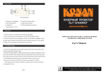
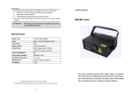
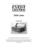
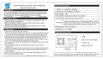
USER MANUAL
THUNDERBOLTGBC
NON-INTERLOCKED HOUSING WARNING
This unit contains high power laser devices internally. Do not open the
laser housing, due to potential exposure to unsafe levels of laser radiation.
The laser power levels accessible if the unit is opened can cause instant
blindness, skin burns and fires.
LASER EMISSION DATA
Laser Classification
Class 3B
Green Laser Medium
DPSS Nd:YVO4, 532nm
Blue Laser Medium
LD GeAs 450nm, typical
Beam Diameter
<5mm at aperture
Pulse Data
All pulses < 4Hz (>0.25sec)
Divergence (each beam)
<2 mrad
Divergence (total light)
<160 degrees
Laser Power
Green>40mW, Blue >80mW
As measured under IEC measurement conditions for classification.
Version: 1.0
This manual contains important laser operation information. Read and
understand all instructions prior to powering on laser unit the first time, to
avoid laser eye injury and to avoid breaking the law. Keep this manual in a
safe place for future reference.
PRODUCT OVERVIEW
This device has left out premises in absolutely perfect condition. In order to
maintain this condition and to ensure a safe operation, it is necessary for the
user to follow the safety instructions and warning notes written in this
manual.
1
USER MANUAL
The manufacturer will not accept liability for any resulting damages caused
by the non-observance of this manual or any unauthorized modification to
the device.
NO.
NAME
1
Power LED
2
Music LED
DESCRIPTION
Indicates the fixture is switched on
Synchronize to detected music signal
The laser effect output aperture. NEVER LOOK INSIDE THE
3
Laser Aperture
FIXTURE THROUGH THIS APERTURE WHILE FIXTURE IS
OPERATING.
4
Power Switch
Switch ON and OFF the fixture
5
Fuse Holder
The replaced fuse is hold here
6
Main Power Input
With IEC socket and integrated fuse holder.
7
DMX Input/Output
3 pins male/female XLR connector
2
USER MANUAL
To turn the laser effect (laser diode) ON/OFF. Be sure that only
authorized operator hold the key
8
Key Switch
9
Safety Eye
10
Control panel
11
Microphone
Used to attach a safety cable when the fixture is rigged. Check
more details in RIGGING
To control the fixture with digital LED display, check more
information on CONTROL & FUNCTION
To detect the music/sound signal
CONTROL & FUNCTION
Regular breaks during operation are essential to maximize the life of this
device as it is not designed for continual use.
Do not switch the unit on and off in short time intervals
Always unplug the unit when it is not used for a longer time. Or before
replacing the bulb or start servicing.
In the event of serious operation problems, stop using the fixture and
contact your dealer immediately.
ATTENTION:
Laser will be output from laser aperture in 5 seconds
after the unit is powered on.
Operation
3
USER MANUAL
Stand Alone Preprogram Laser Show
Press FUNC to enter MODE OPTION.
Till to LED panel shows either one of Auc, Auv, Aug, Agv, Soc, Sor, Sov, Sgv.
Press UP or DOWN to select your favorite Stand Alone mode as above.
Press ENTER to confirm the setting.
The laser is working in stand alone. Each time when you turn on your laser, you
will have this confirmed laser show.
In the MODE OPTION setting, the stand alone laser show that you are going to
choose is flashing. Press UP or DOWN to change stand alone laser show, you will
have 8 different stand alone preprogrammed laser show. Their DISPLAY and
EFFECT are listed below:
DISPLAY
STAND ALONE MODE LASER EFFECT
Auc
AUTOMATIC SHOW with CYAN colors
Auv
AUTOMATIC SHOW with single VIOLET color
Aug
AUTOMATIC SHOW with single GREEN color
Agv
AUTOMATIC SHOW with single GVC color
Soc
SOUND ACTIVATED SHOW with CYAN colors
Sov
SOUND ACTIVATED SHOW with single VIOLET color
Sog
SOUND ACTIVATED SHOW with single GREEN color
Sgv
SOUND ACTIVATED SHOW with single GVC color
SOUND ACTIVATED MODE sensitivity setting
Press FUNC till to see S 6
4
USER MANUAL
Press UP/DOWN to set microphone sensitivity. S 0 is no sound activated,
from S 1 to S 9, the sensitivity level is going more sensitive.
Press ENTER to confirm and save the setting.
DMX MODE
Press FUNC to enter MODE OPTION
Till to LED panel shows 001.
Press ENTER to confirm the setting.
The laser is working in “DMX MODE”. With help of UP/DOWN button, it could be
easily change the DMX address of the laser.
MASTER/SLAVE MODE
Press FUNC to enter MODE OPTION
Till to LED panel shows SLA
Press ENTER to confirm the setting.
The laser is working in “SLAVE MODE”. Connect MASTER laser and SLAVE
lasers with DMX cable, the SLAVE lasers do what exactly MASTER laser does.
Check “5.2 DMX connection” to have more details about laser connection.
TESTING MODE
Press FUNC to enter MODE OPTION
Till to LED panel shows tSt
5
USER MANUAL
Press ENTER to confirm the setting.
The laser is working in “TESTING MODE”. In this mode a fixed testing pattern is
done which people could see how the laser projector working. PS: This mode is
for service only.
DMX PROTOCOL
CHANNEL
VALUE
FUNCTION
000-029
AUTOMATIC SHOW with CYAN colors
030-059
AUTOMATIC SHOW with single VIOLET color
060-089
AUTOMATIC SHOW with single GREEN color
090-119
AUTOMATIC SHOW with single GVC color
120-149
SOUND ACTIVATED SHOW with CYAN colors
150-179
SOUND ACTIVATED SHOW with single VIOLET color
180-209
SOUND ACTIVATED SHOW with single GREEN color
210-239
SOUND ACTIVATED SHOW with single GVC color
240-255
DMX MODE
000-255
32 Patterns as shown in PATTERN LIST
000-024
BLACKOUT
025-049
ORIGINAL PREPROGRAMED COLOR
050-074
VIOLET
075-099
GREEN
CH 3
100-124
CYAN
COLOR
125-149
ALTERNATE
150-174
ALTERNATE GREEN & CYAN
175-199
ALTERNATE VIOLET & CYAN
200-224
ALTERNATE VIOLET & GREEN & CYAN
225-255
Color rolling
CH 1
MODE
CH 2
CH 4
COLOR
CHANGING
SPEED
00-004
005-255
0-127
VIOLET & GREEN
STOP
SLOW --> FAST
100%-5% Size
6
USER MANUAL
CH 5
128-169
Zooming In
ZOOMING
170-209
Zooming Out
210-255
Zooming In & Out
CH 6
000-127
128 different fixed position on X
X AXIS
128-191
Clockwise moving
MOVING
128-255
Anticlockwise moving
CH 7
000-127
128 different fixed position on Y
Y AXIS
128-191
Clockwise moving
MOVING
128-255
Anticlockwise moving
CH 8
000-127
0 -359 degree fixed Y axis rolled
y AXIS
ROLLING
128-191
Clockwise rolling
192-255
Anticlockwise rolling
CH 9
000-127
0 -359 degree fixed X axis rolled
x AXIS
ROLLING
128-191
Clockwise rolling
192-255
Anticlockwise rolling
CH 10
000-127
0 -359 degree fixed Z axis rotate
Z AXIS
128-191
Clockwise rotating
ROTATING
128-255
Anticlockwise rotating
PATTERN LIST IN CHANNEL 2
DMX
PATTERNS
DMX
PATTERNS
DMX
PATTERNS
DMX
000-007
064-071
128-135
190-197
008-015
072-079
136-143
198-205
016-023
080-087
144-151
206-213
7
PATTERNS
USER MANUAL
024-031
088-095
152-159
214-221
032-039
096-103
160-167
222-229
040-047
104-111
168-175
230-237
048-055
112-119
176-181
238-245
056-063
120-127
182-189
246-255
SPECIFICATIONS
Mains Input:
Fuse:
Total Power:
Music Control:
Laser Power:
Laser Classification:
Laser Safety Standard:
Condition Temperature:
DMX Connections:
DMX Channels
Measurement:
N Weight:
AC100-240V, 50/60Hz
250V 1 A Slow Blow (20mm Glass)
12W
Internal microphone
80mW-B + 120mW-C +40mW-G
Class 3B
EN60825-1 2007
10~40
3 pins XLR Male/Female
10 channels
145x160x80mm
1.3 Kg
Specifications subject to change without prior notice.
The availability of particular products may vary by region. Please check with the dealer.
8