1
CANopen communication profile
for servo amplifiers of the
SERVOSTAR™ 600 series
Technical Description, Commissioning Instructions
Edition 01/99
Previous editions
Editions Comments
01 / 99
First edition, valid from software versions 1.57
Technical changes to improve the performance of the equipment
may be made without prior notice !
Printed in the Federal Republic of Germany 01/99
Mat.No. 90810
All rights reserved. No part of this work may be reproduced in any form (by printing, photocopying
microfilm or any other method) or stored, processed, copied or distributed by electronic means,
without the written permission of Seidel Corporation.
Kollmorgen
Contents
01.99
Contents
Drawing
Page
Contents . . . . . . . . . . . . . . . . . . . . . . . . . . . . . . . . . . . . . . . . . . . . . . . . . . . . . . . . . . 3
Abbreviations / Symbols . . . . . . . . . . . . . . . . . . . . . . . . . . . . . . . . . . . . . . . . . . . . . 5
I
General
I.1
I.2
I.3
I.4
I.5
II
About this manual . . . . . . . . . . . . . . . . . . . . . . . . . . . . . . . . . . . . . . . . . . . . . . . . . . . . . . . . . . . . . . . . . . . . . . . . . . . . . . . . . 7
Permitted use (“Use as directed”) of the CANopen interface . . . . . . . . . . . . . . . . . . . . . . . . . . . . . . . . . . . . . . . . . . . . . . . . 7
Features of the CANopen communication profile . . . . . . . . . . . . . . . . . . . . . . . . . . . . . . . . . . . . . . . . . . . . . . . . . . . . . . . . . 8
Numerical format . . . . . . . . . . . . . . . . . . . . . . . . . . . . . . . . . . . . . . . . . . . . . . . . . . . . . . . . . . . . . . . . . . . . . . . . . . . . . . . . . . 9
Bus cable . . . . . . . . . . . . . . . . . . . . . . . . . . . . . . . . . . . . . . . . . . . . . . . . . . . . . . . . . . . . . . . . . . . . . . .-.A.4.031.1/36
................9
Installation / Commissioning
II.1
Assembly, installation . . . . . . . . . . . . . . . . . . . . . . . . . . . . . . . . . . . . . . . . . . . . . . . . . . . . . . . . . . . . . . . . . . . . . . . . . . . . . 11
II.1.1
Connection methods . . . . . . . . . . . . . . . . . . . . . . . . . . . . . . . . . . . . . . . . . . . . . . . . . . . . . . . . . . . . . . . . . . . . . . . . . 11
II.1.2
Setting the station address. . . . . . . . . . . . . . . . . . . . . . . . . . . . . . . . . . . . . . . . . . . . . . . . . . . . . . . . . . . . . . . . . . . . . 11
II.2
Commissioning . . . . . . . . . . . . . . . . . . . . . . . . . . . . . . . . . . . . . . . . . . . . . . . . . . . . . . . . . . . . . . . . . . . . . . . . . . . . . . . . . . 12
III
Software Protocol
III.1 General description of CAN. . . . . . . . . . . . . . . . . . . . . . . . . . . . . . . . . . . . . . . . . . . . . . . . . . . . . . . . . . . . . . . . . . . . . . . . . 13
III.2 Format of a Communication Object (COB). . . . . . . . . . . . . . . . . . . . . . . . . . . . . . . . . . . . . . . . . . . . . . . . . . . . . . . . . . . . . 13
III.3 Construction of the COB Identifier . . . . . . . . . . . . . . . . . . . . . . . . . . . . . . . . . . . . . . . . . . . . . . . . . . . . . . . . . . . . . . . . . . . 13
III.3.1
Default values of the COB-ID in CANopen. . . . . . . . . . . . . . . . . . . . . . . . . . . . . . . . . . . . . . . . . . . . . . . . . . . . . . . 14
III.4 Instrument control . . . . . . . . . . . . . . . . . . . . . . . . . . . . . . . . . . . . . . . . . . . . . . . . . . . . . . . . . . . . . . . . . . . . . . . . . . . . . . . . 14
III.4.1
Status machine . . . . . . . . . . . . . . . . . . . . . . . . . . . . . . . . . . . . . . . . . . . . . . . . . . . . . . . . . . . . . . . . . . . . . . . . . . . . . 15
III.4.1.1 States of the status machine . . . . . . . . . . . . . . . . . . . . . . . . . . . . . . . . . . . . . . . . . . . . . . . . . . . . . . . . . . . . . . . 15
III.4.1.2 Transitions of the status machine . . . . . . . . . . . . . . . . . . . . . . . . . . . . . . . . . . . . . . . . . . . . . . . . . . . . . . . . . . . 16
III.4.2
Control word . . . . . . . . . . . . . . . . . . . . . . . . . . . . . . . . . . . . . . . . . . . . . . . . . . . . . . . . . . . . . . . . . . . . . . . . . . . . . . . 17
III.4.2.1 Bit assignments of the control word . . . . . . . . . . . . . . . . . . . . . . . . . . . . . . . . . . . . . . . . . . . . . . . . . . . . . . . . . 17
III.4.2.2 Commands of the control word. . . . . . . . . . . . . . . . . . . . . . . . . . . . . . . . . . . . . . . . . . . . . . . . . . . . . . . . . . . . . 17
III.4.2.3 Mode-dependent bits in the control word . . . . . . . . . . . . . . . . . . . . . . . . . . . . . . . . . . . . . . . . . . . . . . . . . . . . . 17
III.4.2.4 Description of the other bits in the control word . . . . . . . . . . . . . . . . . . . . . . . . . . . . . . . . . . . . . . . . . . . . . . . 18
III.4.3
Status word . . . . . . . . . . . . . . . . . . . . . . . . . . . . . . . . . . . . . . . . . . . . . . . . . . . . . . . . . . . . . . . . . . . . . . . . . . . . . . . . 18
III.4.3.1 Bit assignments of the status word . . . . . . . . . . . . . . . . . . . . . . . . . . . . . . . . . . . . . . . . . . . . . . . . . . . . . . . . . . 18
III.4.3.2 States of the status machine . . . . . . . . . . . . . . . . . . . . . . . . . . . . . . . . . . . . . . . . . . . . . . . . . . . . . . . . . . . . . . . 18
III.4.3.3 Description of the other bits in the status word. . . . . . . . . . . . . . . . . . . . . . . . . . . . . . . . . . . . . . . . . . . . . . . . . 19
III.5 Communication profile . . . . . . . . . . . . . . . . . . . . . . . . . . . . . . . . . . . . . . . . . . . . . . . . . . . . . . . . . . . . . . . . . . . . . . . . . . . . 19
III.5.1
Administrative Messages . . . . . . . . . . . . . . . . . . . . . . . . . . . . . . . . . . . . . . . . . . . . . . . . . . . . . . . . . . . . . . . . . . . . . 19
III.5.2
Service Data Messages . . . . . . . . . . . . . . . . . . . . . . . . . . . . . . . . . . . . . . . . . . . . . . . . . . . . . . . . . . . . . . . . . . . . . . . 19
III.5.2.1 Description of the Object Dictionary . . . . . . . . . . . . . . . . . . . . . . . . . . . . . . . . . . . . . . . . . . . . . . . . . . . . . . . . 20
III.5.2.2 Description of the Objects. . . . . . . . . . . . . . . . . . . . . . . . . . . . . . . . . . . . . . . . . . . . . . . . . . . . . . . . . . . . . . . . . 22
III.5.2.2.1
Object 1000H: Device Type . . . . . . . . . . . . . . . . . . . . . . . . . . . . . . . . . . . . . . . . . . . . . . . . . . . . . . . . . . 22
III.5.2.2.2
Object 1001H: Error register. . . . . . . . . . . . . . . . . . . . . . . . . . . . . . . . . . . . . . . . . . . . . . . . . . . . . . . . . . 22
III.5.2.2.3
Object 1002H: Manufacturer Status Register (Warnings) . . . . . . . . . . . . . . . . . . . . . . . . . . . . . . . . . . . 23
III.5.2.2.4
Object 1003H: Predefined Error-field. . . . . . . . . . . . . . . . . . . . . . . . . . . . . . . . . . . . . . . . . . . . . . . . . . . 24
III.5.2.2.5
Object 1008H: Manufacturer Device Name . . . . . . . . . . . . . . . . . . . . . . . . . . . . . . . . . . . . . . . . . . . . . . 24
III.5.2.2.6
Object 100AH: Manufacturer Software Version . . . . . . . . . . . . . . . . . . . . . . . . . . . . . . . . . . . . . . . . . . 24
III.5.2.2.7
Object 100BH: Node-ID . . . . . . . . . . . . . . . . . . . . . . . . . . . . . . . . . . . . . . . . . . . . . . . . . . . . . . . . . . . . . 24
III.5.2.2.8
Object 100CH: Guard Time . . . . . . . . . . . . . . . . . . . . . . . . . . . . . . . . . . . . . . . . . . . . . . . . . . . . . . . . . . 25
III.5.2.2.9
Object 100DH: Lifetime Factor . . . . . . . . . . . . . . . . . . . . . . . . . . . . . . . . . . . . . . . . . . . . . . . . . . . . . . . 25
III.5.2.2.10 Object 2020H: Position controller . . . . . . . . . . . . . . . . . . . . . . . . . . . . . . . . . . . . . . . . . . . . . . . . . . . . . 26
III.5.2.2.11 Object 2022H: Positioning data for Positioning Mode . . . . . . . . . . . . . . . . . . . . . . . . . . . . . . . . . . . . . . 29
III.5.2.2.12 Object 2024H: Setting-up for Positioning Mode . . . . . . . . . . . . . . . . . . . . . . . . . . . . . . . . . . . . . . . . . . 34
III.5.2.2.13 Object 2060H: Setpoints for Digital Mode . . . . . . . . . . . . . . . . . . . . . . . . . . . . . . . . . . . . . . . . . . . . . . . 36
III.5.2.2.14 Object 2070H: Actual values . . . . . . . . . . . . . . . . . . . . . . . . . . . . . . . . . . . . . . . . . . . . . . . . . . . . . . . . . 37
III.5.2.2.15 Object 2600H: 1st receive-PDO select . . . . . . . . . . . . . . . . . . . . . . . . . . . . . . . . . . . . . . . . . . . . . . . . . . 40
III.5.2.2.16 Object 2601H: 2nd receive-PDO select . . . . . . . . . . . . . . . . . . . . . . . . . . . . . . . . . . . . . . . . . . . . . . . . . . 41
III.5.2.2.17 Object 2A00H: 1st transmit-PDO select . . . . . . . . . . . . . . . . . . . . . . . . . . . . . . . . . . . . . . . . . . . . . . . . . 41
III.5.2.2.18 Object 2A01H: 2nd transmit-PDO select . . . . . . . . . . . . . . . . . . . . . . . . . . . . . . . . . . . . . . . . . . . . . . . . . 42
III.5.2.2.19 Object 3100H: ASCII channel . . . . . . . . . . . . . . . . . . . . . . . . . . . . . . . . . . . . . . . . . . . . . . . . . . . . . . . . 42
III.5.2.2.20 Object 605AH: Quick Stop Option Code . . . . . . . . . . . . . . . . . . . . . . . . . . . . . . . . . . . . . . . . . . . . . . . . 42
III.5.2.2.21 Object 6060H / 6061H: Modes of Operation . . . . . . . . . . . . . . . . . . . . . . . . . . . . . . . . . . . . . . . . . . . . . 43
CANopen for SERVOSTAR™
3
Contents
Contents
01.99
Kollmorgen
Drawing
Page
III.5.3
Process Data Messages . . . . . . . . . . . . . . . . . . . . . . . . . . . . . . . . . . . . . . . . . . . . . . . . . . . . . . . . . . . . . . . . . . . . . . . 43
III.5.3.1 Receive-PDOs . . . . . . . . . . . . . . . . . . . . . . . . . . . . . . . . . . . . . . . . . . . . . . . . . . . . . . . . . . . . . . . . . . . . . . . . . . 44
III.5.3.1.1
PDO control word . . . . . . . . . . . . . . . . . . . . . . . . . . . . . . . . . . . . . . . . . . . . . . . . . . . . . . . . . . . . . . . . . . 44
III.5.3.1.2
PDO receive ASCII channel . . . . . . . . . . . . . . . . . . . . . . . . . . . . . . . . . . . . . . . . . . . . . . . . . . . . . . . . . 44
III.5.3.1.3
PDO current or speed setpoint . . . . . . . . . . . . . . . . . . . . . . . . . . . . . . . . . . . . . . . . . . . . . . . . . . . . . . . . 45
III.5.3.1.4
PDO Setpoint 2 . . . . . . . . . . . . . . . . . . . . . . . . . . . . . . . . . . . . . . . . . . . . . . . . . . . . . . . . . . . . . . . . . . . . 45
III.5.3.1.5
PDO trajectory (in preparation) . . . . . . . . . . . . . . . . . . . . . . . . . . . . . . . . . . . . . . . . . . . . . . . . . . . . . . . 46
III.5.3.1.6
PDO motion block
. . . . . . . . . . . . . . . . . . . . . . . . . . . . . . . . . . . . . . . . . . . . . . . . . . . . . . . . . . . . . . . 46
III.5.3.1.7
PDO start motion block . . . . . . . . . . . . . . . . . . . . . . . . . . . . . . . . . . . . . . . . . . . . . . . . . . . . . . . . . . . . . 47
III.5.3.2 Transmit-PDOs . . . . . . . . . . . . . . . . . . . . . . . . . . . . . . . . . . . . . . . . . . . . . . . . . . . . . . . . . . . . . . . . . . . . . . . . . 47
III.5.3.2.1
PDO status word . . . . . . . . . . . . . . . . . . . . . . . . . . . . . . . . . . . . . . . . . . . . . . . . . . . . . . . . . . . . . . . . . . . 47
III.5.3.2.2
PDO transmit ASCII channel . . . . . . . . . . . . . . . . . . . . . . . . . . . . . . . . . . . . . . . . . . . . . . . . . . . . . . . . . 47
III.5.3.2.3
PDO actual position . . . . . . . . . . . . . . . . . . . . . . . . . . . . . . . . . . . . . . . . . . . . . . . . . . . . . . . . . . . . . . . . 48
III.5.3.2.4
PDO extended status . . . . . . . . . . . . . . . . . . . . . . . . . . . . . . . . . . . . . . . . . . . . . . . . . . . . . . . . . . . . . . . . 48
III.5.3.2.5
PDO actual position 2 . . . . . . . . . . . . . . . . . . . . . . . . . . . . . . . . . . . . . . . . . . . . . . . . . . . . . . . . . . . . . . . 48
III.5.3.2.6
PDO incremental actual position . . . . . . . . . . . . . . . . . . . . . . . . . . . . . . . . . . . . . . . . . . . . . . . . . . . . . . 49
III.5.4
Predefined Communication Objects . . . . . . . . . . . . . . . . . . . . . . . . . . . . . . . . . . . . . . . . . . . . . . . . . . . . . . . . . . . . . 49
III.5.4.1 Sync Object . . . . . . . . . . . . . . . . . . . . . . . . . . . . . . . . . . . . . . . . . . . . . . . . . . . . . . . . . . . . . . . . . . . . . . . . . . . . 49
III.5.4.2 Emergency Object . . . . . . . . . . . . . . . . . . . . . . . . . . . . . . . . . . . . . . . . . . . . . . . . . . . . . . . . . . . . . . . . . . . . . . . 49
III.5.4.3 Time Stamp Object . . . . . . . . . . . . . . . . . . . . . . . . . . . . . . . . . . . . . . . . . . . . . . . . . . . . . . . . . . . . . . . . . . . . . . 50
IV
User Notes and Examples
IV.1
IV.2
IV.3
IV.4
IV.5
IV.6
IV.7
IV.8
IV.9
IV.10
IV.11
IV.12
IV.13
IV.14
IV.15
IV.16
IV.17
IV.18
IV.19
V
Appendix
V.1
4
Commissioning the CAN-bus master. . . . . . . . . . . . . . . . . . . . . . . . . . . . . . . . . . . . . . . . . . . . . . . . . . . . . . . . . . . . . . . . . . 51
Layout . . . . . . . . . . . . . . . . . . . . . . . . . . . . . . . . . . . . . . . . . . . . . . . . . . . . . . . . . . . . . . . . . . . . . . . . . . . . . . . . . . . . . . . . . 51
Status query 1. . . . . . . . . . . . . . . . . . . . . . . . . . . . . . . . . . . . . . . . . . . . . . . . . . . . . . . . . . . . . . . . . . . . . . . . . . . . . . . . . . . . 51
Switch On. . . . . . . . . . . . . . . . . . . . . . . . . . . . . . . . . . . . . . . . . . . . . . . . . . . . . . . . . . . . . . . . . . . . . . . . . . . . . . . . . . . . . . . 51
Status query 2. . . . . . . . . . . . . . . . . . . . . . . . . . . . . . . . . . . . . . . . . . . . . . . . . . . . . . . . . . . . . . . . . . . . . . . . . . . . . . . . . . . . 52
Enable Operation . . . . . . . . . . . . . . . . . . . . . . . . . . . . . . . . . . . . . . . . . . . . . . . . . . . . . . . . . . . . . . . . . . . . . . . . . . . . . . . . . 52
Mode query . . . . . . . . . . . . . . . . . . . . . . . . . . . . . . . . . . . . . . . . . . . . . . . . . . . . . . . . . . . . . . . . . . . . . . . . . . . . . . . . . . . . . 52
Homing parameters . . . . . . . . . . . . . . . . . . . . . . . . . . . . . . . . . . . . . . . . . . . . . . . . . . . . . . . . . . . . . . . . . . . . . . . . . . . . . . . 52
Start homing . . . . . . . . . . . . . . . . . . . . . . . . . . . . . . . . . . . . . . . . . . . . . . . . . . . . . . . . . . . . . . . . . . . . . . . . . . . . . . . . . . . . . 53
Switch-on position control . . . . . . . . . . . . . . . . . . . . . . . . . . . . . . . . . . . . . . . . . . . . . . . . . . . . . . . . . . . . . . . . . . . . . . . . . . 53
Map second Receive-PDO . . . . . . . . . . . . . . . . . . . . . . . . . . . . . . . . . . . . . . . . . . . . . . . . . . . . . . . . . . . . . . . . . . . . . . . . . 53
Switch NMT status machine to “operational” . . . . . . . . . . . . . . . . . . . . . . . . . . . . . . . . . . . . . . . . . . . . . . . . . . . . . . . . . . 53
Contact second Receive Object . . . . . . . . . . . . . . . . . . . . . . . . . . . . . . . . . . . . . . . . . . . . . . . . . . . . . . . . . . . . . . . . . . . . . . 53
Motor Quick Stop. . . . . . . . . . . . . . . . . . . . . . . . . . . . . . . . . . . . . . . . . . . . . . . . . . . . . . . . . . . . . . . . . . . . . . . . . . . . . . . . . 53
Inhibit controller . . . . . . . . . . . . . . . . . . . . . . . . . . . . . . . . . . . . . . . . . . . . . . . . . . . . . . . . . . . . . . . . . . . . . . . . . . . . . . . . . 54
Test for Sync-telegrams . . . . . . . . . . . . . . . . . . . . . . . . . . . . . . . . . . . . . . . . . . . . . . . . . . . . . . . . . . . . . . . . . . . . . . . . . . . . 54
Sync Object . . . . . . . . . . . . . . . . . . . . . . . . . . . . . . . . . . . . . . . . . . . . . . . . . . . . . . . . . . . . . . . . . . . . . . . . . . . . . . . . . . . . . 54
Emergency Object . . . . . . . . . . . . . . . . . . . . . . . . . . . . . . . . . . . . . . . . . . . . . . . . . . . . . . . . . . . . . . . . . . . . . . . . . . . . . . . . 54
ASCII communication . . . . . . . . . . . . . . . . . . . . . . . . . . . . . . . . . . . . . . . . . . . . . . . . . . . . . . . . . . . . . . . . . . . . . . . . . . . . . 55
Index. . . . . . . . . . . . . . . . . . . . . . . . . . . . . . . . . . . . . . . . . . . . . . . . . . . . . . . . . . . . . . . . . . . . . . . . . . . . . . . . . . . . . . . . . . . 57
CANopen for SERVOSTAR™
Kollmorgen
Abbreviations / Symbols
01.99
Abbreviations used in this manual
The abbreviations used in this manual are explained in the table below.
Abbr.
AGND
BTB/RTO
CE
CLK
COM
DGND
DIN
Disk
EEPROM
EMC
EN
IEC
ISO
LED
MB
MS-DOS
NI
NSTOP
Meaning
Analog ground
Ready to operate (standby)
European Community (Communité Européenne)
Clock
Serial interface of a PC-AT
Digital ground
Deutsches Institut für Normung
(German Standards Institute)
Magnetic storage (diskette, hard disk)
Electrically erasable/programmable memory
Electromagnetic compatibility
European standard
International Electrotechnical Commission
International Standardization Organization
Light-emitting diode
Megabyte
Operating system for a PC-AT
Null pulse (zero mark)
Limit-switch for CCW (left) rotation
Abbr.
PC-AT
PGND
PSTOP
RAM
RBallast
RBext
RBint
RES
ROD
PLC
SRAM
SSI
SW/SETP.
UL
V AC
V DC
VDE
XGND
Meaning
Personal computer with an 80x86 processor
Ground for the interface that is used
Limit-switch for CW (right) rotation
Volatile memory
Ballast resistor
External ballast resistor
Internal ballast resistor
Resolver
Incremental position indicator
Programmable logic controller
Static RAM
Synchronous serial interface
Setpoint
Underwriters Laboratories
Alternating voltage
Constant voltage
Verein deutscher Elektrotechniker
(Society of German electrical technicians)
Ground for the 24V supply
Symbols used in this manual
danger to personnel
from electricity
and its effects
ð
see Chapter (cross-reference)
CANopen for SERVOSTAR™
general warning
general instructions
mechanical hazard
l
special emphasis
5
Kollmorgen
01.99
This page has been deliberately left blank.
6
CANopen for SERVOSTAR™
Kollmorgen
General
01.99
I
General
I.1
About this manual
This manual describes the commissioning, range of functions and software protocol of the
SERVOSTAR™ 600 servo amplifier with the CANopen communication profile. It forms part of
the complete documentation for the SERVOSTAR™ 600 family of servo amplifiers.
The installation and commissioning of the servo amplifier, as well as all standard functions, are
described in the corresponding installation manuals.
Other parts of the complete documentation for the SERVOSTAR™ 600 family of digital
servo amplifiers:
Title
Operator Software SR600.EXE for SERVOSTAR™ 600
User Manual
Digital servo amplifier SERVOSTAR™ 600
Assembly, Installation and Commissioning Instructions
Publisher
Order No.
Seidel
90464
Seidel
89370
Additional documentation:
Publisher
Title
CAN Application Layer (CAL) for Industrial Applications
CiA e.V.
Draft standards 102, 201..207, 301
CiA e.V.
CAN Specification Version 2.0
Philips Semiconductors
ISO 11898 ...Controller area network (CAN) for high-speed communication
Drive technology profile / Profile 21
DRIVECOM
Drive technology profile / Servo 22
DRIVECOM
This manual has the following requirements for qualified personnel:
Wiring
Programming
:
:
Professionally qualified electrical technicians
Software developers, CAN-BUS project-planners
Training and familiarization courses are available on request.
I.2
Permitted use (“Use as directed”) of the CANopen interface
Please consider the chapter “Use as directed” in the installation/commissioning manual of the
SERVOSTAR™ 600.
The interface is a component of the digital servoamplifiers from the SERVOSTAR™ 600 series.
The CANopen interface serves only for the connection of the servo amplifier to a master via
the CAN-bus.
The servo amplifiers are components that are built into electrical apparatus or machinery, and can
only be commissioned as integral components of such apparatus or machinery.
Only when the components that we specify are used and the installation regulations are followed can we guarantee the conformity of the servo amplifier with the following standards
for industrial areas:
EC EMC Directive
89/336/EEC
EC Low-Voltage Directive
73/23/EEC
CANopen for SERVOSTAR™
7
General
I.3
Kollmorgen
01.99
Features of the CANopen communication profile
When working with the position controller in the SERVOSTAR™ 600 digital servo amplifier, the
following functions are available:
Setting-up and general functions:
—
—
—
homing, set reference point
jogging, with a variable speed
provision of a digital setpoint for speed and torque control
Positioning functions:
—
—
—
execution of a motion task from the motion block memory of the servo amplifier
execution of a direct motion task
absolute trajectory (in preparation)
Data transfer functions:
—
—
—
—
—
—
transmit a motion task to the motion block memory of the servo amplifier
A motion task consists of the following elements:
» position setpoint (absolute task) or path setpoint (relative task)
» speed setpoint
» acceleration time, braking time, rate-of-change limiting (if required)
» type of motion task (absolute/relative)
» number of a following task (with or without pause)
read a motion task from the motion block memory of the servo amplifier
read actual values
read the error register
read the status register
read/write control parameters (via the ASCII channel)
System requirements:
—
—
Servo amplifier SERVOSTAR ™ 600
Master station with a CAN-BUS interface (e.g. PC with CAN interface)
Transmission procedure:
—
—
8
Bus connection and bus medium: CAN-Standard ISO 11898 (CAN high-speed)
transmission rate: max. 1Mbit/s
possible settings for the servo amplifier:
10, 20, 50, 100, 125, 250, 333, 500, 666, 800, 1000kBaud
CANopen for SERVOSTAR™
Kollmorgen
I.4
01.99 - A.4.031.1/36
General
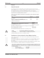
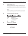
Numerical format
Not only parameter numbers, but also parameter values are expected to be in the Little-Endian
("Intel") -format (see below).
INTEGER16
address n+0:
address n+1:
bit 7 .. 0 (LSB)
bit 15 .. 8 (MSB)
INTEGER32
address n+0:
address n+1:
address n+2:
address n+3:
bit 7 .. 0 (LSB)
bit 15 .. 8
bit 23 .. 16
bit 31 .. 24 (MSB)
Interpretation:
n
address (absolute)
LSB Least Significant Bit
MSB Most Significant Bit
Negative numbers are represented as 2’s complement.
I.5
Bus cable
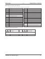
In accordance with ISO 11898 you should use a bus cable with a characteristic impedance of
120 Ω . The usable cable length for reliable communication is reduced as the transmission rate is
increased. The following values that we have measured can be used as a guide. They should not,
however, be interpreted as limiting values:
Cable data:
characteristic impedance
100-120 Ω
cable capacitance
max. 60 nF/km
lead resistance (loop)
159.8 Ω/km
Cable length, dependent on the transmission rate
Transmission rate / kBaud
1000
500
250
max. cable length / m
20
70
115
Longer transmission distances may be achieved with a lower cable capacitance (max. 30 nF/km)
and lower lead resistance (loop, 115 Ω/km).
(characteristic impedance 150 ± 5Ω ⇒ termination resistance 150 ± 5Ω).
For EMC reasons, the SubD connector housing must fulfill the following requirements:
—
metal or metallized housing
—
provision for connecting the cable shielding in the housing, with a large contact area.
Special clamp-terminal connectors (order number 90650), that are available from Seidel Servo
Drives, can easily be made up for bus operation.
CANopen for SERVOSTAR™
9
General
Kollmorgen
01.99
This page has been deliberately left blank.
10
CANopen for SERVOSTAR™
Kollmorgen
01.99
II
Installation / Commissioning
II.1
Assembly, installation
Installation / Commissioning
Only install and wire up the equipment in a de-energized condition, i.e. neither the
mains/line supply voltage nor the 24V auxiliary voltage nor the operating voltage of any
other connected equipment may be switched on.
Take care that the switchgear cabinet is safely disconnected (lockout, warning signs etc.).
The individual voltages are switched on for the first time during commissioning.
Never disconnect the electrical connections to the servo amplifier while it is live. This could
cause destruction of the electronics.
Residual charges in the capacitors can still have dangerous levels several minutes after
switching off the supply power. Measure the voltage in the DC-link circuit and wait until
the voltage has fallen below 40V.
Even when the motor is not rotating, power and control cables can still be live.
Set up the station address for the servo amplifier on the CAN-bus ( ð II.1.2).
Assemble the servo amplifier as described in the installation instructions for SERVOSTAR™ 600.
Observe all safety instructions in the installation instructions that belong to the servo amplifier.
Follow all the notes on mounting position, ambient conditions, wiring, and fusing / overload
protection.
The connections for the motor, controls and power, as well as advice on system layout for EMCconformance, can be found in the installation instructions for the servo amplifier.
II.1.1
Connection methods
Supply power, motor :
Analog setpoints :
Digital control signals :
CAN connection :
II.1.2
see installation instructions for SERVOSTAR™ 600
see installation instructions for SERVOSTAR™ 600
see installation instructions for SERVOSTAR™ 600
see installation instructions for SERVOSTAR™ 600
Setting the station address
The station address (instrument address on the CAN-Bus) for the servo amplifier can be set up in
two different ways:
l
by using the pushbuttons on the front panel
(see commissioning instructions for SERVOSTAR™ 600)
l
by using the “ADDR” command (see reference list of ASCII commands)
CANopen for SERVOSTAR™
11
Installation / Commissioning
II.2
Kollmorgen
01.99
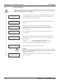
Commissioning
Only professional personnel with extensive knowledge of control and drive technology are
allowed to commission the servo amplifier.
Check assembly /
installation
Check that all the safety instructions in the installation instructions for the
servo amplifier and this manual have been observed and implemented.
Check the setting for the station address.
Connect PC, start
operator software
Use the operator software SR600.EXE to set the parameters for the servo
amplifier.
Commission
the basic functions
Start up the basic functions of the servo amplifier and optimize the
current and speed controllers. This section of the commissioning is
described in detail in the installation and commissioning instructions for
the servo amplifier.
Save
parameters
Start up the
bus communication
Test the
communication
When the parameters have been successfully optimized, save them in
servo amplifier.
The altered parameters will only become effective after a software-reset
(Warmboot). To do this, change to the screen page “Status” and operate
the reset button.
Requirement:
the software protocol described in Chapter III
must be implemented in the master.
Adjust the baud rate of the SERVOSTAR™ to match the master.
Recommendation : request the Emergency Object.
Caution !
Make sure that any unintended movement of the drive cannot endanger
machinery or personnel.
Commission the
position controller
12
Commission the position controller, as described in the manual for the
operator software.
CANopen for SERVOSTAR™
Kollmorgen
Software Protocol
01.99
III
Software Protocol
III.1
General description of CAN
The transmission method that is used here is defined in ISO 11898 (Controller Area Network
CAN) for high-speed communication). The Layer-1/2 protocol (Physical Layer/Data Link Layer)
that is implemented in all CAN modules provides, amongst other things, the requirement for data.
Data transport or data request is made by means of a data telegram (Data Frame) with up to 8 bytes
of user data, or by a data request telegram (Remote Frame).
Communication Objects are labeled by an 11-bit Identifier (ID) that also determines the priority of
Objects.
A Layer-7 protocol (Application Layer) was developed, to decouple the application from the communication. The service elements that are provided by the Application Layer make it possible to
implement an application that is spread across the network. These service elements are described
in the CAN Application Layer (CAL) for Industrial Applications.
The Communication Profile CANopen and the drive profile are mounted on the CAL.
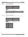
III.2
Format of a Communication Object (COB)
S
O
M
R
T
R
COB-ID
SOM
COB-ID
RTR
CTRL
Data Segment
Data Segment
CRC
A
C
K
EOM
Start of message
COB-Identifier (11-bit)
Remote Transmission Request
Control Field (i.e. Data Length Code)
0...8 Byte (Data-COB)
0
Byte (Remote-COB)
Cyclic Redundancy Check
Acknowledge Slot
End of message
CRC
ACK
EOM
III.3
CTRL
Construction of the COB Identifier
10
9
8
7
6
Function code
Bit 0- 6
Bit 7-10
5
4
3
2
1
0
Module-ID
Module ID (station number, range 1 ... 63; is set up in the operator software or the
servo amplifier, ð II.1.2)
Warning: If an invalid station number (=0 or >63) is set up, then the module-ID
will be set internally to 1.
Function Code (number of the Communication Object that is defined in the server)
CANopen for SERVOSTAR™
13
Software Protocol
III.3.1
Kollmorgen
01.99
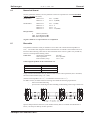
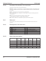
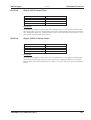
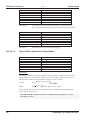
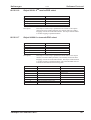
Default values of the COB-ID in CANopen
The following table shows the default values for the COB Identifier after switching on the servo
amplifier. The objects that are provided with an index (Communication Parameters at Index), can
have a new ID assigned after the initialization phase. The indices in brackets are optional.
Object
NMT
SYNC
TIME STAMP
EMERGENCY
PDO 1 (tx*)
POD 1 (rx*)
PDO 2 (tx)
PDO 2 (rx)
SDO (tx)
SDO (rx)
Nodeguard
*
III.4
Function code (binary)
0000
0001
0010
0001
0011
0100
0101
0110
1011
1100
1110
Resulting COB-IDs
0
128
256
129 ... 255
385 ... 511
513 ... 639
641 ... 767
769 ... 895
1409 ... 1535
1537 ... 1663
1793 ... 1919
Communication parameters at index
--(1005H)
----1800H
1400H
1801H
1401H
(100EH)
tx = direction of transmission SERVOSTAR™ ⇒ Master
rx = direction of transmission Master ⇒ SERVOSTAR™
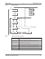
Instrument control
The instrument control of the SERVOSTAR™ can be used to carry out all the motion functions in
the corresponding modes. The control of the SERVOSTAR™ is implemented through a modedependent status machine. The status machine is controlled through the control word (Þ III.4.2).
The mode setting is made through the Object “Modes of Operation” (Þ III.5.2.2.21). The states of
the status machine can be revealed by using the status word (Þ III.4.3).
control word (6040H)
operating mode
status machine
modes of
operation
(6060H)
status word
(6041H)
14
CANopen for SERVOSTAR™
Kollmorgen
Software Protocol
01.99
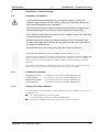
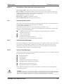
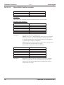
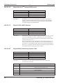
III.4.1
Status machine
Power
disabled
Fault disabled
Fault reaction
active
Start
14
0
Not ready to
switch on
Fault
1
15
Switch-on
disabled
2
7
Ready to
switch on
3
6
10
12
Power enabled
9
8
Switched on
4
5
Operation
enabled
III.4.1.1
11
16
Quick Stop
active
States of the status machine
State
Description
SERVOSTAR™ is not ready to switch on, there is no operational readiness
Not Ready to Switch On
(BTB) reported from the controller program.
SERVOSTAR™ is ready to switch on, parameters can be transferred, the DC-link
Switch On Disabled
voltage can be switched on, motion functions cannot yet be carried out.
DC-link voltage must be switched on, parameters can be transferred,
Ready to Switch On
motion functions cannot yet be carried out.
DC-link voltage must be switched on, parameters can be transferred, motion
Switched On
functions cannot yet be carried out, output stage is switched on (enabled).
Operation Enabled
No error present, output stage is enabled, motion functions are enabled.
Drive has been stopped with the emergency ramp, output stage is enabled, motion
Quick Stop Active
functions are enabled, response depends on Object 605AH (ð III.5.2.2.20)
Fault Reaction Active
not supported at present
Fault
not supported at present
CANopen for SERVOSTAR™
15
Software Protocol
III.4.1.2
Kollmorgen
01.99
Transitions of the status machine
The state transitions are affected by internal events (e.g. switching off the DC-link voltage) and by
the flags in the control word (bits 0,1,2,3,7).
Transition
0
1
2
Event
Reset
Initialization completed successfully.
SERVOSTAR™ is ready to operate.
Bit 1 (Disable Voltage) and Bit 2
(Quick Stop) are set in the control
word (‘Shutdown’ command).
DC-link voltage is present.
3
Bit 0 is also set
(‘Switch On’ command)
4
Bit 3 is also set
(‘Enable Operation’ command)
5
Bit 3 is canceled
(‘Disable Operation’ command)
6
7
8
9
10
11
12
13
14
15
16
Bit 0 is canceled
(‘Shutdown’ command)
Bits 1/2 are canceled (‘Quickstop’ /
‘Disable Voltage’ command)
Bit 0 is canceled
(‘Shutdown’ command)
Bit 1 is canceled
(‘Disable Voltage’ command)
Bits 1/2 are canceled (’Quickstop’ /
‘Disable Voltage’ command)
Bit 2 is canceled
(’Quickstop’ command)
Bit 1 is canceled
(‘Disable Voltage’ command)
not supported at present
not supported at present
not supported at present
Bit 2 is set
Action
Initialization
none
none
Output stage is switched on (enabled), provided
that the hardware enable is present (logical AND).
Drive has torque.
Motion function is enabled, depending on the mode
that is set.
Motion function is inhibited. Drive is stopped, using
the relevant ramp (mode-dependent).
The current position is maintained.
Output stage is disabled. Drive has no torque.
none
Output stage is switched off (disabled).
Motor has no torque.
Output stage is disabled.
Motor has no torque.
Motion function is enabled, depending on the mode
that is set.
Drive is stopped with the emergency braking ramp.
The output stage remains enabled.
Setpoints are canceled (motion block number, digital
setpoint, speed for jogging or homing).
Bit 2 must be set again before any further motion
tasks can be performed.
Output stage is disabled.
Motor has no torque.
none
none
none
Motion function is enabled again.
Caution !
If the servo amplifier is operated through the control word / status word, then no control
commands may be sent through another communication channel (RS232, CANopen,
ASCII channel, Option board).
16
CANopen for SERVOSTAR™
Kollmorgen
Software Protocol
01.99
III.4.2
Control word
III.4.2.1
Bit assignments of the control word
Bit
0
1
2
3
4
5
6
7
III.4.2.2
Name
Switch on
Disable Voltage
Quick Stop
Enable Operation
Mode-dependent
Mode-dependent
Mode-dependent
Reset Fault (only effective for faults)
Bit
8
9
10
11
12
13
14
15
Name
Pause
reserved
reserved
Acknowledge lag error and response monitoring
Reset position
Manufacturer-specific
Manufacturer-specific
Manufacturer-specific
Commands of the control word
Command
Bit 2
Bit 3
Quick Stop
Enable
Operation
Shutdown
X
X
1
Switch on
X
X
1
Disable Voltage
X
X
X
Quick Stop
X
X
0
Disable Operation
X
0
1
Enable Operation
X
1
1
Fault Reset
Not supported
X
X
Bits marked with X are irrelevant.
III.4.2.3
Bit 7
Fault Reset
Bit 1
Disable
Voltage
1
1
0
1
1
1
X
Transitions
Bit 0
Switch on
0
1
X
X
1
1
X
2, 6, 8
3
7, 9, 10, 12
7, 10, 11
5
4, 16
15
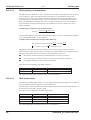
Mode-dependent bits in the control word
The following table describes the mode-dependent bits in the control word. Only manufacturerspecific modes are supported at present. The individual modes are set by the “Modes of
operation” Object (Index 6060H).
Operating mode
Position
Digital speed
Digital current
Analog speed
Analog current
Trajectory
Homing
Jog mode
CANopen for SERVOSTAR™
Bit 4
reserved
reserved
reserved
reserved
reserved
reserved
start homing
reserved
Bit 5
reserved
reserved
reserved
reserved
reserved
reserved
reserved
reserved
Bit 6
reserved
reserved
reserved
reserved
reserved
reserved
reserved
reserved
17
Software Protocol
III.4.2.4
Kollmorgen
01.99
Description of the other bits in the control word
The other bits of the control word are described below.
Bit 8 Pause If Bit 8 is set, then the drive is stopped (paused) in all modes. The setpoints (speed
for homing or jogging, motion task number, setpoints for digital mode) for the individual modes
are retained.
Bit 9,10 These Bits are reserved for the drive profile (DS402).
Bit 11 Acknowledge error Setting Bit 11 acknowledges the response monitoring and/or the
contouring error.
Bit 12 reset the position, taking into account the reference offset.
(see also homing type number 6 in object 2024H, subindex 1)
Bit 13, 14, 15 These bits are manufacturer-specific, and reserved at present.
III.4.3
Status word
The momentary state of the status machine can be read out with the aid of the status word
(Þ III.4.3).
III.4.3.1
Bit assignments of the status word
Bit
0
1
2
3
4
5
6
7
III.4.3.2
Name
Ready to switch on
Switched on
Operation enable
Fault (in preparation)
Disable voltage
Quick stop
Switch on disabled
Warning (in preparation)
Name
Manufacturer-specific (reserved)
Remote (in preparation)
Target reached (in preparation)
Internal limit active (in preparation)
Operation mode dependent (reserved)
Operation mode dependent (reserved)
Manufacturer-specific (reserved)
Manufacturer-specific (reserved)
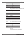
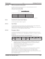
States of the status machine
State
Bit 6
switch on
disable
0
1
0
0
0
Not ready to switch on
Switch on disabled
Ready to switch on
Switched on
Operation enabled
Fault
Fault reaction active
Quick stop active
0
The bits marked with X are irrelevant.
18
Bit
8
9
10
11
12
13
14
15
Bit 5
quick stop
X
X
1
1
1
0
Bit 3
fault
Bit 2
operation
enable
0
0
0
0
0
0
0
0
0
1
not supported at present
not supported at present
0
1
Bit 1
switched on
0
0
0
1
1
Bit 0
ready to
switch on
0
0
1
1
1
1
1
CANopen for SERVOSTAR™
Kollmorgen
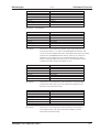
III.4.3.3
01.99
Software Protocol
Description of the other bits in the status word
Bit 4: voltage_disable The DC-link voltage is present when this bit is canceled.
Bit 7: warning (not supported at present). There may be several reasons which have led to this
warning and the setting of Bit 7. The reason for this warning can be revealed by using the Object
1002H “manufacturer-specific status register”. (Þ III.5.2.2.3)
Bit 9: remote (not supported at present)
Bit 10: target_reached (not supported at present)
Bit 11: internal_limit_active (not supported at present)
III.5
Communication profile
This Chapter does not describe the method of operation of the CANopen Communication Profile,
but the handling of the Objects that are implemented and used
(e.g. SDO, PDO, EMERGENCY, ... ).
The foundation for this is the CAL (CAN Application Layer DS201...207).
Four types of message (Messages / Objects) can be distinguished, according to their functionality
(s. DS 301). They are described below:
III.5.1
l
“Administrative Messages” (Layer Management, Network Management, Identifier
Distribution Messages)
l
“Service Data Messages”
l
“Process Data Messages”
l
“Predefined Communication Objects”
(Synchronization/ Time-Stamp/Emergency Messages).
Administrative Messages
The network management is implemented according to the CANopen standard. The corresponding
status machine is implemented according to the state diagram that supports the four states of
Initialization, Pre-operational, Prepared, Operational. The status machine is operated with the
corresponding NMT-messages (e.g. Start Remote Node).
III.5.2
Service Data Messages
In accordance with the CAL specification (DS202-1), the following services are supported through
the aid of the Service Data Objects (SDO):
l
Domain Download
l
Domain Upload
l
Abort Domain
l
Initiate Domain Download (in preparation)
l
Download Domain Segment (in preparation)
l
Initiate Domain Upload (in preparation)
l
Upload Domain Segment (in preparation)
The construction and method of operation of the SDOs can be found in the CANopen (DS301)
Communication Profile.
Caution!
It is always necessary to wait for the response to an SDO that is sent to the SERVOSTAR™
before a new telegram can be sent to it. There is no buffering of the commands.
CANopen for SERVOSTAR™
19
Software Protocol
III.5.2.1
01.99
Kollmorgen
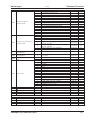
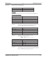
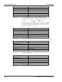
Description of the Object Dictionary
The following table describes the Object Dictionary. The first column includes the Index for the
Object. If the Object is a structure, then the subindices are listed in the corresponding column
according to the CANopen convention.
If it is not possible to process a component of a PDO (e.g. because a limit is exceeded), then the
further processing of the PDO is interrupted and an EMERGENCY Object is transmitted. An
appropriate label for the faulty component is then entered in the manufacturer-specific area of the
Object. (ð III.5.4.2)
For certain parameters, a reference in brackets points to the ASCII commands that are described in
the reference manual.
Index
Description des Index
Communication profile area (DS 301)
1000H
Unit type
1001H
Error register
Manufacturer-specific
1002H
status register
Subindex Description / Reference
Data type
Access
-----
ð III.5.2.2.1
ð III.5.2.2.2
32-bit Int.
8-bit Char
r
r
---
ð III.5.2.2.3
32-bit Int.
r
0
8-bit Char
No. of entries(ð III.5.2.2.4)
1
Last reported error
32-bit Int.
1005H
COB-ID SYNC message
--See CANopen (DS 301)
32-bit Int.
4 Char
--1008H
Unit name
ð III.5.2.2.5
--4 Char
100AH Software version
ð III.5.2.2.6
--32-bit Int.
100BH Node address
ð III.5.2.2.7
--16-bit Int.
100CH Guard time
ð III.5.2.2.8
8-bit Char
--100DH Lifetime factor
ð III.5.2.2.9
Receive-PDO communication parameter (DS 301)
--RECORD
1400H
1st receive-PDO parameter
ð III.5.3.1
--RECORD
1401H
2nd receive-PDO parameter
ð III.5.3.1
Receive-PDO mapping parameter (DS 301)
--RECORD
1600H
1st receive-PDO mapping
ð III.5.3.1
--RECORD
1601H
2nd receive-PDO mapping
ð III.5.3.1
Transmit-PDO communication parameter (DS 301)
RECORD
--1800H
1st transmit-PDO parameter
ð III.5.3.2
--RECORD
1801H
2nd transmit-PDO parameter
ð III.5.3.2
Transmit-PDO mapping parameter (DS 301)
RECORD
--1A00H 1st transmit-PDO mapping
ð III.5.3.2
--RECORD
1A01H 2nd transmit-PDO mapping
ð III.5.3.2
Device profile drives and motion control (DSP 402) / manufacturer specific profile area (DSP 402)
2000H
Current controller (in preparation)
0
Number of entries
8-bit Char
2010H
Speed controller (in preparation)
0
Number of entries
8-bit Char
0
Number of entries
8-bit Char
1
Axis type (see Com. “POSCNFG”)
8-bit Char
In-Position window
2
32-bit Int.
(see Com. “PEINPOS”)
Contouring error window
3
32-bit Int.
(see Com. “PEMAX”)
4
Position register 1 (see Com. “SWE1”)
32-bit Int.
2020H
Position controller
5
Position register 2 (see Com. “SWE2”)
32-bit Int.
6
Position register 3 (see Com. “SWE3”)
32-bit Int.
7
Position register 4 (see Com. “SWE4”)
32-bit Int.
Denominator resolution
8
32-bit UInt
(see Com. “PGEARO”)
Numerator resolution
9
32-bit UInt
(see Com. “PGEARI”)
10
Count direction (see Com. “DIR”)
8-bit Char
1003H
20
Predefined error field
r
r/w
r
r
r
r
r/w
r/w
r
r
r
r/w
r/w
r/w
r/w
r/w
r/w
r/w
r/w
r/w
r/w
CANopen for SERVOSTAR™
Kollmorgen
Index
Description of the Index
2022H
Position data for the
‘Position’ mode
2024H
Setting-up operation for the
‘Position’ mode
01.99
Subindex
0
1
2
3
4
5
6
7
8
9
10
11
12
13
14
0
1
2
3
6
7
Description / Reference
No. of entries (ð III.5.2.2.10)
Position
Speed
Motion task type
Trajectory
Motion task number (see Com. “MOVE”)
Acceleration time [Accel.]
Braking time [Decel.]
Rate-of-change limiting [Acceleration]
Rate-of-change limiting [Deceleration]
Number of the following tasks
Start delay for following task
Copy a motion task (see Com. “COPY”)
Weighting factor Speed for PDO motion block
Speed for direct motion task
No. of entries
Homing type (see Com. “NREF”)
Homing direction (see Com. “DREF”)
Homing speed (see Com. “VREF”)
Acceleration ramp [jogging & homing]
(see Com. “ACCR”)
Braking ramp [jogging & homing]
(see Com. “DECR”)
Reference offset (see Com. “ROFFS”)
Jogging speed (see Com. “VJOG”)
0
No. of entries
8-bit Char
r
0
No. of entries
8-bit Char
r
0
1
0
1
2
3
4
5
6
7
8
9
10
11
12
13
14
15
16
-----------
No. of entries
Speed or current setpoint
No. of entries
Actual position (20 bits / turn)
Revs/min.
Incremental position value (see Com. “PFB”)
Reserve
Reserve
Position (resolution-dependent) (see Com. “PRD”)
Speed (resolution-dependent)
contouring error (resolution-dependent)
Current (r.m.s.) (see Com. “I”)
Speed (see Com. “v”)
Heat sink temperature (see Com. “TEMPH”)
Internal temperature (see Com. “TEMPE”)
DC-link voltage (see Com. “VBUS”)
Ballast power (see Com. “PBAL”)
I2T loading (see Com. “I2T”)
Operational time (see Com. “TRUN”)
ð III.5.2.2.15
ð III.5.2.2.16
ð III.5.2.2.17
ð III.5.2.2.18
ð III.5.2.2.19
8-bit Char
32-bit Int.
8-bit Char
32-bit Int.
32-bit Int.
32-bit Int.
----32-bit Int.
32-bit Int.
32-bit Int.
32-bit Int.
32-bit Int.
32-bit Int.
32-bit Int.
32-bit Int.
32-bit Int.
32-bit Int.
32-bit Int.
8-bit Char
8-bit Char
8-bit Char
8-bit Char
8-bit Char
r
rw
r
r
r
r
----r
r
r
r
r
r
r
r
r
r
r
r/w
r/w
r/w
r/w
r/w
-----------
ð III.4.2
ð III.4.3
ð III.5.2.2.20
ð III.5.2.2.21
ð III.5.2.2.21
16-bit Int.
16-bit Int.
16-bit Int.
8-bit Char
8-bit Char
w
r
r/w
w
r
4
5
2040H
2050H
2060H
2070H
Motor parameter
(in preparation)
General parameter
(in preparation)
Setpoints for the ‘Digital’
mode
Actual values
2600H 1st receive-PDO select
2601H 2nd receive-PDO select
2A00H 1st transmit-PDO select
2A01H 2nd transmit-PDO select
3100H ASCII-character direction
Device control (DSP 402)
6040H Control word
6041H Status word
605AH Quickstop option code
6060H Modes of operation
6061H Modes of operation display
Software Protocol
CANopen for SERVOSTAR™
Data type Access
8-bit Char
r
32-bit Int.
r/w
16-bit Int.
r/w
16-bit UInt
r/w
32-bit Int.
r/w
16-bit UInt
r/w
16-bit UInt
r/w
16-bit UInt
r/w
16-bit UInt
r/w
16-bit UInt
r/w
16-bit UInt
r/w
16-bit UInt
r/w
2x16-bit UInt
w
16-bit
r/w
32-bit Int.
r/w
8-bit Char
r
8-bit Char
r/w
8–bit Char
r/w
32–bit Int.
r/w
16-bit UInt
r/w
16-bit UInt
r/w
32-bit Int.
32-bit Int.
r/w
r/w
21
Software Protocol
Kollmorgen
01.99
III.5.2.2
Description of the Objects
III.5.2.2.1
Object 1000H: Device Type
Index
Brief description
Access
Data type
Value range
1000H
description of the type of device
r
Integer32
see below
Description:
The type of device is defined by a 32 Bit data element.
MSB
LSB
Additional Information
Output stage ID
Device type
31
III.5.2.2.2
24 23
Device-profile number
402D
16 15
Device Profile Number:
402D
Device type:
2D (Servo Drive)
0
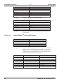
Object 1001H: Error register
If an error bit is set in the error register, then detailed information is made available in Object
1003H.
Index
Brief description
Access
Data type
Value range
1001H
error register
r
Unsigned8
see below
Description:
The bit assignments in the error register are described below.
Bit
0
1
2
3
4
5
6
7
22
Description
generic error
current
voltage
temperature
communication error
device profile specific
reserved
manufacturer-specific
CANopen for SERVOSTAR™
Kollmorgen
III.5.2.2.3
01.99
Software Protocol
Object 1002H: Manufacturer Status Register (Warnings)
Index
Brief description
Access
Data type
Value range
1002H
manufacturer-specific status register
r
Unsigned32
see below
Bit assignments :
Bit
0
1
2
3
4
5
6
7
8
9
10
11
12
13
14
15
16
17
18
19
20
21
22
23
24
25
26
27
28
29
30
31
Value
1
1
1
1
1
1
1
1
1
1
1
1
1
1
1
1
1
1
1
1
1
1
1
1
1
1
1
1
1
1
1
1
Description
Warning 1: I²t-signal threshold exceeded
Warning 2: ballast power reached
Warning 3: contouring error
Warning 4: response monitoring is active
Warning 5: supply phase missing
Warning 6: software limit-switch 1 was triggered
Warning 7: software limit-switch 2 was triggered
Warning 8: faulty motion task started
Warning 9: no reference point set at start of motion task
Warning 10: PSTOP active
Warning 11: NSTOP active
Warning 12: motor default values were loaded
Warning 13: expansion board not functioning correctly
Warning 14: reserve
Warning 15: reserve
Warning 16: reserve
motion task active
reference point set
actual position = Home Position
In Position
----Position 1 reached
Position 2 reached
Position 3 reached
Position 4 reached
Initialization is finished
--speed = 0
safety relay has been triggered
output stage enabled
error present
CANopen for SERVOSTAR™
23
Software Protocol
III.5.2.2.4
Kollmorgen
01.99
Object 1003H: Predefined Error-field
Index
Brief description
Object code
Number of elements
1003H
Predefined error-field
RECORD
1
Description of the subindex:
Subindex
Brief description
Access
Data type
Description:
III.5.2.2.5
01H
last error recorded
rw
Unsigned32
This Object can be used to read out the last Emergency Object that was
recorded. Only subindices 0 and 1 according to CANopen DS301
are supported.
Object 1008H: Manufacturer Device Name
Index
Brief description
Access
Data type
1008H
device name
r
Visible string
Description :
The device name consists of four ASCII characters, and contains the letters “S6xx”, whereby xx
stands for the size of the current in the output stage (e.g. S606).
III.5.2.2.6
Object 100AH: Manufacturer Software Version
Index
Brief description
Access
Data type
100AH
software version
r
Visible string
Description :
The interface-software version consists of four ASCII characters (e.g. 0.04).
III.5.2.2.7
Object 100BH: Node-ID
Index
Brief description
Access
Data type
Value range
100BH
station address
r
Unsigned32
1 ... 63
Description :
The station address can be output through the Object “Node-ID”.
24
CANopen for SERVOSTAR™
Kollmorgen
III.5.2.2.8
01.99
Software Protocol
Object 100CH: Guard Time
Index
Brief description
Access
Data type
Value range
100CH
guard time
rw
Unsigned16
0 ... 65535
Description :
The product of the Objects “Guard Time” and “Lifetime Factor” is the response monitoring time.
The “Guard Time” is given in milliseconds. The response monitoring first becomes active with the
first “Nodeguard” Object (see CANopen DS301). If the value of the “Guard Time” Object is set to
zero, then the response monitoring is inactive.
III.5.2.2.9
Object 100DH: Lifetime Factor
Index
Brief description
Access
Data type
Value range
100DH
Lifetime Factor
rw
Unsigned8
0 ... 255
Description :
The product of the Objects “Guard Time” and “Lifetime Factor” is the response monitoring time.
The response monitoring first becomes active with the first “Nodeguard” Object (see CANopen
DS301). If the value of the “Lifetime Factor” Object is set to zero, then the response monitoring is
inactive.
CANopen for SERVOSTAR™
25
Software Protocol
III.5.2.2.10
Kollmorgen
01.99
Object 2020H: Position controller
Index
Brief description
Object code
Number of elements
2020H
parameter for the position controller
RECORD
10
Description :
This index is used to define all the general parameters for the ‘Position’ mode.
Description of the subindices :
Subindex
Brief description
Dimensional unit
Access
PDO mapped
Data type
Value range
Default value
Description :
01H
axis type
--rw
no
Unsigned8
0, 1
0
Describes the type of the mechanical axis.
Value 0: Linear axis. A defined reference point is used as the origin for
measuring positions. This must be defined by a homing operation, or
by setting a reference point. The movement of the axis will be limited
by software limit-switches (if configured).
Value 1: Rotary axis. Does not require a reference point. The position is
set to 0 at the start of motion blocks or jogging.
Software limit-switches do not limit the movement.
Subindex
Brief description
Dimensional unit
Access
PDO mapped
Data type
Value range
Default value
Description :
26
02H
In-Position window
µm
rw
no
Integer32
-(231-1)..(231-1)
4000H
Determines a target window for positioning. If the limit of the target
window is reached, Bit 19 is set in the manufacturer-specific status
register, and, if the output is appropriately configured, the selected
output will be set to High.
CANopen for SERVOSTAR™
Kollmorgen
01.99
Subindex
Brief description
Dimensional unit
Access
PDO mapped
Data type
Value range
Default value
Description :
03H
maximum contouring error
µm
rw
no
Integer32
-(231-1)..(231-1)
40000H
Defines a maximum value for the contouring error. If the contouring
error that arises exceeds this value, then the drive is stopped.
The infringement of the contouring error limit is indicated through
Bit 2 of the manufacturer-specific status register.
If the value is set to 0, the contouring error will not be monitored.
Subindex
Brief description
Dimensional unit
Access
PDO mapped
Data type
Value range
Default value
Description :
04H
Position register 1
µm
rw
no
Integer32
-(231-1)..(231-1)
0
Depending on configuration, going above or below the preset position
value results in a threshold bit being set (Bit 22 of the manufacturerspecific status register) or the axis being stopped. (Going below software
limit-switch 1 = manufacturer-specific status register Bit 5 = 1)
Subindex
Brief description
Dimensional unit
Access
PDO mapped
Data type
Value range
Default value
Description :
05H
Position 2
mm
rw
no
Integer32
-(231-1)..(231-1)
0
Depending on configuration, going above or below the preset position
value results in a threshold bit being set (Bit 23 of the manufacturerspecific status register) or the axis being stopped. (Going above software
limit-switch 2 = manufacturer-specific status register Bit 6 = 1)
Subindex
Brief description
Dimensional unit
Access
PDO mapped
Data type
Value range
Default value
Description :
Software Protocol
06H
Position register 3
mm
rw
no
Integer32
-(231-1)..(231-1)
0
Depending on the configuration, going above or below the preset position
value results in a threshold bit being set (Bit 24 of the manufacturer-specific
status register).
CANopen for SERVOSTAR™
27
Software Protocol
Subindex
Brief description
Dimensional unit
Access
PDO mapped
Data type
Value range
Default value
Description :
Subindex
Brief description
Dimensional unit
Access
PDO mapped
Data type
Value range
Default value
Description :
Subindex
Brief description
Dimensional unit
Access
PDO mapped
Data type
Value range
Default value
Description :
Subindex
Brief description
Dimensional unit
Access
PDO mapped
Data type
Value range
Default value
Description :
28
Kollmorgen
01.99
07H
Position register 4
mm
rw
no
Integer32
-(231-1)..(231-1)
0
Depending on the configuration, going above or below the preset position
value results in a threshold bit being set (Bit 25 of the manufacturer-specific
status register).
08H
Resolution: denominator of the conversion
factor
turns
rw
no
Unsigned32
1 ... (231 –1)
1
see Subindex 09H
09H
Resolution: numerator of the conversion factor
µm
rw
no
Unsigned32
1 ... (231 –1)
1
The ratio of the subindices 8 and 9 defines the mechanical
resolution of the axis in µm/turn.
0AH
count direction
--rw
no
Unsigned8
0, 1
1
The value represents the count direction for current, speed and
position control.
A value of 1 selects the positive direction of counting. Positive
setpoint entries result in the motor shaft rotating in the clockwise
direction (looking at the end of the shaft).
CANopen for SERVOSTAR™
Kollmorgen
III.5.2.2.11
01.99
Software Protocol
Object 2022H: Positioning data for Positioning Mode
Index
Brief description
Object code
Number of elements
2022H
motion task parameter
RECORD
12
Description :
This index is used to enter all the parameters that are relevant to direct motion tasks or tasks that
are stored in the controller. (See ASCII command “ORDER”)
Description of the subindices :
Subindex
Brief description
Dimensional unit
Access
PDO mapped
Data type
Value range
Default value
Description :
01H
Position
increments or mm
rw
PDO 34 (rx)
Integer32
-(231-1)..(231-1)
0
This index is used to define the target position (absolute motion task) or
distance to be travelled (relative motion task) for motion tasks.
This is selected by Bit 0 of the motion task type. Bit 13 of the motion
task type determines whether the value that is presented should be
interpreted as an increment or as an SI-value.
Subindex
Brief description
Dimensional unit
Access
PDO mapped
Data type
Value range
Default value
Description:
02H
Set speed
increments/sec or mm/sec
rw
PDO 34 (rx)
Integer32
-(231-1)..(231-1)
0
This index is used to define the set speed for motion tasks. If the value is
defined as an SI dimensional unit by motion task type Bit 13 = 1, then
the incremental speed vi is given by
PGEARO
, where PGEARO (Index 2020, Subindex 8)
v =v *
PGEARI * 4000
contains the number of increments to be travelled, and where the distance
to be travelled is PGEARI (=Index 2020, Subindex 9). It must be noted
that here one turn of the motor is equivalent to 220 = 1048576 increments.
i
CANopen for SERVOSTAR™
SI
29
Software Protocol
Subindex
Brief description
Dimensional unit
Access
PDO mapped
Data type
Value range
Default value
Description:
01.99
Kollmorgen
03H
type of motion task
--rw
PDO 34 (rx)
Unsigned16
0 ... 65535
0
This index is used to set motion parameters for the motion task.
In this case, the bits have the following interpretations:
Bit
Val. Interpretation
0 The given position value (Subindex 1) is evaluated as an absolute position.
0
The given position value is evaluated as a relative distance to be travelled.
1
The two following bits will then decide the type of relative motion.
If Bit 1 and Bit 2 are set to 0, and Bit 0 is 1, then the relative motion task is
0
performed according to the state of the “InPosition” bit.
1
The new target position is given by the current position plus the distance to be travelled.
1
Bit 1 has priority to Bit 2.
If Bit 1 and Bit 2 are set to 0, and Bit 0 is 1, then the relative motion task is
0
performed according to the state of the “InPosition” Bit.
2
1 The new target position is given by the current position plus the distance to be travelled.
0 No following task available
3
1 There is a following task that must be defined through the subindex 0AH.
0 Switch over to the following task, braking to speed 0 at the target position.
4
Switch over to the following task, without stopping at the target position.
1
The type of speed transition is set by Bit 8.
0 Switch over to the following task, without evaluating inputs.
5
1 A following task is started through an appropriately configured input.
0 Start the following task by input state Low.
6
Start des following task by input state High or, if Bit 7 = 1, in any case after the delay time
1
that is set by subindex 0BH.
0 The following task is started immediately.
7
The following task is started after the delay time that is set by subindex 0BH or, if Bit 6 = 1,
1
previously, by the appropriate input signal.
Only for following tasks and Bit 4 = 1: On reaching the target position for the motion task, the
0
speed is changed to the value for the following task.
8
The speed changeover is made so that the speed at the target position for the motion task has
1
already reached the value for the following task.
9..11 --- reserved
0 Accelerations are calculated from the acceleration and braking times of the motion task.
12
1 A global acceleration value is used to calculate the accel./braking ramps (in preparation).
0 The target position and target speed of a motion task are interpreted as increments.
The target position and target speed are converted to increments before the start of the motion
13
1 task.
This is done by using the parameters PGEARI and PGEARO (see subindex 02H)
0 The programmed speed is used as the motion task speed.
14
The speed for the motion task is determined by the voltage present at analog input SW1 when
1
the motion task starts.
15
--- reserved
30
CANopen for SERVOSTAR™
Kollmorgen
01.99
Subindex
Brief description
Dimensional unit
Access
PDO mapped
Data type
Value range
Default value
Software Protocol
04H
trajectory
--rw
PDO 33 (rx)
Integer32
-(231-1)..(231-1)
0
Description: In preparation
Subindex
Brief description
Dimensional unit
Access
PDO mapped
Data type
Value range
Default value
Description:
05H
motion task number
--rw
PDO 35 (rx)
Unsigned16
1 ... 180, 129 ... 255
0
This index is used to define the number of the selected motion task.
Note that the task nos. 1 to 180 are for EEPROM motion blocks, and
192 to 255 are for RAM motion tasks. The RAM motion tasks are loaded
with the first 64 EEPROM motion tasks at switch-on, or if the servo
amplifier is reset. Motion task 0 is also a RAM motion task, that is
used as a copying buffer for motion tasks, or for entering the motion
task data for a direct motion task (PDO (rx) 34).
Subindex
Brief description
Dimensional unit
Access
PDO mapped
Data type
Value range
Default value
Description:
06H
accel. time (acceleration)
ms
rw
no
Unsigned16
1 ... 65535
0
This index is used to define the total time taken to reach the target
speed for the motion task. The value selected for subindex 8 sets
the form of the acceleration ramp.
Subindex
Brief description
Dimensional unit
Access
PDO mapped
Data type
Value range
Default value
Description:
07H
braking time (deceleration)
ms
rw
no
Unsigned16
1 ... 65535
0
This index is used to define the total time taken to reach speed 0
at the target positon. The value selected for subindex 9 sets the
form of the acceleration ramp.
CANopen for SERVOSTAR™
31
Software Protocol
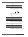
Subindex
Brief description
Dimensional unit
Access
PDO mapped
Data type
Value range
Default value
Description:
Kollmorgen
01.99
08H
rate-of-change limiting (acceleration)
ms
rw
--Unsigned16
1 ... 65535
0
This index is used to define the form of the acceleration ramp.
The value must be set to less than half of the accel. time (subindex 6).
The following diagram illustrates the relationship:
a
T2
T2
t
T1
T1 correponds to subindex 6, T2 to subindex 8.
For T2 = 0, the curve that is followed is a trapezoidal ramp,
T1
for T2 = it is approximately a sin2 curve.
2
Subindex
Brief description
Dimensional unit
Access
PDO mapped
Data type
Value range
Default value
Description:
Subindex
Brief description
Dimensional unit
Access
PDO mapped
Data type
Value range
Default value
Description:
32
09H
rate-of-change limiting (braking)
ms
rw
--Unsigned16
0 ... 65535
0
This index is used to define the form of the braking ramp.
The value must be set to less than half of the braking time (subindex 7).
The rate-of-change limiting has the same effect here as for acceleration.
0AH
number of the following task
--rw
no
Unsigned16
0 ... 180, 192 ... 255
0
This index is used to set the number for a following task.
The setting of subindex 3, Bit 3, determines whether this is used to continue.
CANopen for SERVOSTAR™
Kollmorgen
01.99
Subindex
Brief description
Dimensional unit
Access
PDO mapped
Data type
Value range
Default value
Description:
0BH
start delay for the following task
ms
rw
no
Unsigned16
1 ... 65535
0
This Object is used to set a delay time before the start of the following
motion task. This function must be enabled through subindex 3, Bit 7.
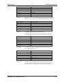
Subindex
Brief description
Dimensional unit
Access
PDO mapped
Data type
Value range
Default value
Description:
0CH
copy a motion task
--w
no
2 x Unsigned16
each 0 ... 180, 192 ... 255
0, 0
This Object can be used to copy motion tasks.
The number that appears first in the CAN telegram describes the
source motion task, the following number is the target motion task.
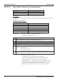
Subindex
Brief description
Dimensional unit
Access
PDO mapped
Data type
Value range
Default value
Description:
0DH
weighting factor for speed
--rw
no
Unsigned16
0 ... 65535
1
This Object is used to set a multiplier for the speed that is given
in the PDO motion block (rx).
Subindex
Brief description
Dimensional unit
Access
PDO mapped
Data type
Value range
Default value
Description:
Software Protocol
0EH
speed for direct motion task
increments / 250µs, or dependent on the resolution
rw
no
Integer32
-(231-1)..(231-1)
0
This Object is used to define the speed for the direct motion task
(motion block 0). The motion task type then determines whether the
speed is evaluated incrementally, or as an SI dimensional unit.
CANopen for SERVOSTAR™
33
Software Protocol
III.5.2.2.12
Kollmorgen
01.99
Object 2024H: Setting-up for Positioning Mode
Index
Brief description
Object code
Number of elements
2024H
parameters for homing and jogging
RECORD
7
Description :
This index is used to enter parameters that are important for the operating modes “Homing” and
“Jogging”.
Description of the subindices :
Subindex
Brief description
Dimensional unit
Access
PDO mapped
Data type
Value range
Default value
Description:
01H
homing
--rw
no
Unsigned8
0 ... 5
0
This index is used to set the type of homing.
The following settings are possible:
Value Interpretation
The reference point is set to the current (actual) position.
0
The actual position that is signalled is then the preset reference offset.
1
Homing to reference switch, with subsequent search of the resolver zero point.
2
Homing to limit-switch, with subsequent search of the resolver zero point.
3
Homing to reference switch, without subsequent search of the resolver zero point.
4
Homing to limit switch, without subsequent search of the resolver zero point.
Homing to the resolver zero point, within a motor turn. The direction of travel is given by the
subindex 2. The values mean:
5
0: negative direction of travel
1: positive direction of travel
2: motor turns in the shortest direction to the resolver zero point within a turn.
The reference point is set at the current setpoint position of the position control to the value of the
6
reference offset. The new actual position retains the same distance to the setpoint position as before.
The following must be observed:
For homing 1 and 3 a digital input must be configured
as the zero position input (Home Position). For homing 2 and 4
a digital input must be configured as a hardware limit-switch.
For homing types 1 – 5 the setting of the zero-pulse offset for the ROD
output is taken into account (ASCII command ENCZERO), i.e. the
zero point is fixed so that the output of the zero pulse as well as the
display of the 0-position is made in place of the zero-pulse offset.
34
CANopen for SERVOSTAR™
Kollmorgen
01.99
Subindex
Brief description
Dimensional unit
Access
PDO mapped
Data type
Value range
Default value
Description:
02H
homing direction
--rw
no
Unsigned8
0 ... 2
0
This index is used to define the direction of travel for homing types 1 to 5.
The values have the following meaning:
0: negative direction of travel
1: positive direction of travel
2: motor turns in the shortest direction to the resolver zero point
within a turn. (Only relevant for homing type 5)
Subindex
Brief description
Dimensional unit
Access
PDO mapped
Data type
Value range
Default value
Description:
03H
Speed for homing
µm/sec
rw
no
Integer32
-(231-1)..(231-1)
0
This index is used to define the homing speed.
Subindex
Brief description
Dimensional unit
Access
PDO mapped
Data type
Value range
Default value
Description:
04H
acceleration ramp for jogging/homing
ms
rw
no
Unsigned16
1 ... 32767
10
This index is used to set the acceleration ramp for homing and
jogging operations. It is implemented as a trapezoidal curve form.
The time that is set refers to the speeds that are set for homing
and jogging.
Subindex
Brief description
Dimensional unit
Access
PDO mapped
Data type
Value range
Default value
Description:
Software Protocol
05H
braking ramp for jogging/homing
ms
rw
no
Unsigned16
1 ... 32767
10
This index is used to set the braking ramp for homing and
jogging operation. It is implemented as a trapezoidal curve form.
The time that is set refers to the speeds that are set for homing
and jogging operations. When homing to a hardware limit-switch,
the emergency ramp (ASCII parameter DECSTOP) is used.
CANopen for SERVOSTAR™
35
Software Protocol
Subindex
Brief description
Dimensional unit
Access
PDO mapped
Data type
Value range
Default value
Description:
06H
reference offset
µm
rw
no
Integer32
-(231-1)..(231-1)
0
This index is used to set the reference offset, i.e. the actual position
that is displayed after homing to the reference (index 2070, subindex 6).
Subindex
Brief description
Dimensional unit
Access
PDO mapped
Data type
Value range
Default value
Description:
III.5.2.2.13
Kollmorgen
01.99
07H
speed for jogging
µm/sec
rw
no
Integer32
-(231-1)..(231-1)
0
This index is used to set the speed for jogging.
Object 2060H: Setpoints for Digital Mode
Index
Brief description
Dimensional unit
Access
PDO mapped
Data type
Value range
Default value
2060H
digital setpoint for current or speed
A, or min1
rw
PDO 22 (rx)
Integer32
-(231-1)..(231-1)
0
Description :
This Object is used for the transfer of digital setpoints which are evaluated according to the
digital mode that is set (mode FDH = digital current, mode FEH = digital speed, can be set
through Object 6060H). The normalization settings are made as follows:
digital current setpoint
Current:
I[ A ] =
Speed:
n[min -1 ] = 1875 262144 * digital current setpoint
1640* I max
A new setpoint will always only become effective after a fresh Enable operation (through
Object 6040H, control word).
The SERVOSTAR™ position controller is switched off when the speed or current
controllers are active.
36
CANopen for SERVOSTAR™
Kollmorgen
III.5.2.2.14
01.99
Software Protocol
Object 2070H: Actual values
Index
Brief description
Object code
Number of elements
2070H
actual values
RECORD
16
Description :
This index is used to make relevant actual values available to the SERVOSTAR™ 600.
Description of the subindices :
Subindex
Brief description
Dimensional unit
Access
PDO mapped
Data type
Value range
Default value
Description:
01H
actual position
--r
PDO 22 (tx), PDO 32 (tx)
Unsigned32
0 ... 16777215
0
This index can be used to read in the motor position, within 16 turns.
One turn is resolved with 20 bits of incremental information.
So, 1 turn Þ 220 increments Þ1048576 increments
Subindex
Brief description
Dimensional unit
Access
PDO mapped
Data type
Value range
Default value
Description:
02H
actual speed
min-1
r
PDO 22 (tx), PDO 32 (tx)
Unsigned32
0 ... 1677215
0
This index can be used to read in the motor speed.
The value for the speed is given by:
n[min -1 ] = 1875 262144 * actual value read in
Subindex
Brief description
Dimensional unit
Access
PDO mapped
Data type
Value range
Default value
Description:
03H
incremental position encoder
--r
PDO 33 (tx)
Integer32
-(231-1)..(231-1)
0
This index can be used to read in the incremental value for the actual
position. One turn is resolved with 20 bits of incremental information.
So, 1 turn Þ 220 increments Þ1048576 increments
CANopen for SERVOSTAR™
37
Software Protocol
Subindex
Brief description
Dimensional unit
Access
PDO mapped
Data type
Value range
Default value
Description:
Kollmorgen
01.99
06H
SI actual position value
µm
r
PDO 22 (tx), PDO 32 (tx)
Integer32
-(231-1)..(231-1)
0
This index reads the actual position in SI dimensional units.
The relationship between the actual distance travelled and motor turns
is given by
S = S * PGEARI PGEARO
whereby PGEARO (= index 2020, subindex 8) contains the number
of increments that are travelled to produce the distance PGEARI
(= index 2020, subindex 9). Note that here one turn corresponds to
incremental number 220 = 1048576.
SI
Subindex
Brief description
Dimensional unit
Access
PDO mapped
Data type
Value range
Default value
Description:
Subindex
Brief description
Dimensional unit
Access
PDO mapped
Data type
Value range
Default value
Description:
Subindex
Brief description
Dimensional unit
Access
PDO mapped
Data type
Value range
Default value
Description:
38
Incr
07H
SI actual speed value
µm/sec
r
no
Integer32
-(231-1)..(231-1)
0
This index can be used to read the actual speed in SI dimensional units.
08H
contouring error
µm
r
no
Integer32
-(231-1)..(231-1)
0
This index can be used to determine the momentary contouring error
in SI dimensional units.
09H
effective (r.m.s.) current
mA
r
no
Unsigned32
0 ... 2 * rated current [mA]
0
This index can be used to read the momentary r.m.s. current.
CANopen for SERVOSTAR™
Kollmorgen
01.99
Subindex
Brief description
Dimensional unit
Access
PDO mapped
Data type
Value range
Default value
Description:
0AH
speed
min-1
r
no
Integer32
-(231-1)..(231-1)
0
This index can be used to read the momentary speed measurement.
Subindex
Brief description
Dimensional unit
Access
PDO mapped
Data type
Value range
Default value
Description:
0BH
heat sink temperature
°C
r
no
Integer32
-(231-1)..(231-1)
0
This index can be used to read the heat sink temperature.
Subindex
Brief description
Dimensional unit
Access
PDO mapped
Data type
Value range
Default value
Description:
0CH
internal temperature
°C
r
no
Integer32
-(231-1)..(231-1)
0
This index can be used to read the internal temperature of the servo
amplifier.
Subindex
Brief description
Dimensional unit
Access
PDO mapped
Data type
Value range
Default value
Description:
0DH
DC-link voltage
V
r
no
Integer32
-(231-1)..(231-1)
0
This index can be used to read the momentary DC-link voltage
measurement.
Subindex
Brief description
Dimensional unit
Access
PDO mapped
Data type
Value range
Default value
Description:
Software Protocol
0EH
ballast power
W
r
no
Integer32
-(231-1)..(231-1)
0
This index be used to read the momentary ballast power.
CANopen for SERVOSTAR™
39
Software Protocol
Subindex
Brief description
Dimensional unit
Access
PDO mapped
Data type
Value range
Default value
Description:
Subindex
Brief description
Dimensional unit
Access
PDO mapped
Data type
Value range
Default value
Description:
III.5.2.2.15
0FH
I2T loading
%
r
no
Integer32
-(231-1)..(231-1)
0
This index can be used to read the I2t loading.
10H
operating time
min
r
no
Integer32
-(231-1)..(231-1)
0
This index can be used to read the operating time counter of the
servo amplifier.
Object 2600H: 1st receive-PDO select
Index
Brief description
Access
Data type
Value range
Default value
Description:
PDO number
1
2 .. 20
21
22 .. 31
32
33
34
35
36 .. 64
40
Kollmorgen
01.99
2600H
selection of the first receive-PDO
rw
Unsigned8
1, 21 ... 24, 32
1
This Object is used to map a predefined receive-PDO to the Objects
1400H (1st receive-PDO parameter) and 1600H (1st receive-PDO
mapping) with the aid of the PDO number. This Object enables a
variable mapping of predefined PDOs. The selectable PDOs that are
available are described in the following table.
PDO name
PDO control word
reserved
ASCII channel
reserved
PDO setpoint
PDO trajectory
PDO motion block
PDO start motion block
reserved
Reference
ð III.5.3.1.1
--ð III.5.3.1.2
--ð III.5.3.1.4
ð III.5.3.1.5
ð III.5.3.1.6
ð III.5.3.1.7
---
CANopen for SERVOSTAR™
Kollmorgen
III.5.2.2.16
Object 2601H: 2nd receive-PDO select
Index
Brief description
Access
Data type
Value range
Default value
Description:
III.5.2.2.17
Software Protocol
01.99
2601H
selection of the second receive-PDO
rw
Unsigned8
1, 21 ... 24, 32
21
This Object is used to map a predefined receive-PDO to the Objects
1401H (2nd receive-PDO parameter) and 1601H (2nd receive-PDO
mapping) with the aid of the PDO number. The Object 2601H enables
a variable mapping of predefined PDOs.
Object 2A00H: 1st transmit-PDO select
Subindex
Brief description
Access
Data type
Value range
Default value
Description:
2A00H
selection of the first transmit-PDO
rw
Unsigned8
1, 21 ... 24, 32
1
This Object is used to map a predefined transmit-PDO to the Objects
1800H (1st transmit-PDO parameter) and 1A00H (1st transmit-PDO
mapping) with the aid of the PDO number. The Object 2A00H enables
a variable mapping of predefined PDOs. The selectable PDOs that are
available are described in the following table.
PDO number
1
2 .. 20
21
22
23
24 .. 31
32
33
34 .. 64
CANopen for SERVOSTAR™
PDO name
PDO status word
reserved
ASCII channel
PDO actual position
PDO extended status
reserved
PDO actual position2
PDO incremental position value
reserved
Reference
ð III.5.3.2.1
---
ð III.5.3.2.2
ð III.5.3.2.3
ð III.5.3.2.4
---
ð III.5.3.2.5
ð III.5.3.2.6
---
41
Software Protocol
III.5.2.2.18
Object 2A01H: 2nd transmit-PDO select
Index
Brief description
Access
Data type
Value range
Default value
Description:
III.5.2.2.19
2A01H
selection of the second transmit-PDO
rw
Unsigned8
1, 21 ... 24, 32
21
This Object is used to map a predefined transmit-PDO to the Objects
1801H (2nd transmit-PDO parameter) and 1A01H (2nd transmit-PDO
mapping) with the aid of the PDO number. The Object 2A01H enables
a variable mapping of predefined PDOs.
Object 3100H: ASCII channel
Index
Brief description
Access
Data type
Value range
Description:
III.5.2.2.20
Kollmorgen
01.99
3100H
transmit and receive ASCII characters
rw
Visible string
---
This Object can be used to transmit and receive ASCII characters, as long
as the status machine is not in the “Operational” state. If less then four
characters are to be transferred, then the unused data Bytes must be filled
with the ASCII code “NUL”.
If the status machine is in the “Operational” state, then the characters can
only be written, with the aid of an SDO, since the mirrored characters or
the response are transmitted by PDO. If the PDO ASCII channel transmit
(PDO 21) is not mapped, then the transmission buffer for ASCII characters
will automatically be cleared, to prevent overflows.
Object 605AH: Quick Stop Option Code
Index
Brief description
Access
Data type
Value range
Default value
Description:
605AH
Quick Stop response
rw
Integer16
–32768 ... 32767
2
This Object is used to define the behavior of the drive in the event
of a Quick Stop command.
Value
Description
–32768 ... –2 Reserved (manufacturer-specific)
Manufacturer-specific
—
-1
0
1
2
3 ... 32767
42
Disable Drive Function
—
Reserved (drive profile)
Slow down on quickstop ramp —
Reserved
response as for Pause (ÞIII.4.2),
using the Quick Stop braking ramp
drive is stopped and immediately disabled
(Switch On Disable)
motion task must be selected again
CANopen for SERVOSTAR™
Kollmorgen
III.5.2.2.21
Software Protocol
01.99
Object 6060H / 6061H: Modes of Operation
Since the following are user-defined modes, the values are negative.
Function
Mode
dec.
-1
-2
-3
-4
-5
-6
-7
-8
Position
Digital speed
Digital current
Analog speed
Analog current
Trajectory
Homing
Jogging
Comments
hex.
FF
FE
FD
FC
FB
FA
F9
F8
the mode required for motion tasks
----not possible with standard version
not possible with standard version
-------
Object 6060H is used to set the mode, and Object 6061H to read the mode that has been set.
After a change of mode the corresponding setpoint must be set again (e.g. homing mode ⇒
setpoint homing speed must be set). If the position or jogging mode is stored, then the homing
mode is set after a RESET of the servo amplifier.
Never change the mode while the motor is running !
A changing of the modes while the amplifier is enabled is only permitted at speed 0.
Set the setpoint to 0 before changing over.
III.5.3
Process Data Messages
Process Data Messages are implemented with the aid of the Process Data Object (PDO)
(see CANopen DS 301). Since CANopen only supports two transmit-PDOs and two receivePDOs, but the drive profile requires more than two PDOs, SDOs can be used to activate the
corresponding PDOs through mapping.
The system distinguishes between two transmission modes – synchronous and asynchronous.
The transmission modes are parameterized through SDOs.
Process Data Objects are assigned to the transmission types with the aid of a Byte value
(0 — 255, see CANopen DS 301). The table shows the various types of transmission.
Transmission type
0
1 ... 240
241 ... 251
252
PDO transmission
acyclic synchronous
cyclic synchronous
reserved
synchronous / only RTR
Transmission type
253
254
255
PDO transmission
asynchronous / only RTR
asynchronous
asynchronous
All transmission types are supported, apart from type 252, whereby the transmission types 254 and
255 are event-triggered (asynchronous type) and are therefore exceptions. The tables that describe
the PDOs show which PDOs can be triggered from particular events.
Receive-PDOs can be selected by the Objects 2600H / 2601H, and transmit-PDOs by the Objects
2A00H / 2A01H. Apart from this, the described default settings are valid
(see the corresponding Object Descriptions).
Caution : in order to be able to perform PDOs, the NMT status machine must be
in the “Operational” state (ð III.4.1).
PDOs should be used with a functional interlock, i.e. after a change in the control word or
the use of th eASCII channel, there must be a wait for the next prompt (-->).
The characteristics of the software mean that the PDOs with numbers above 32 may
possibly be processed more quickly.
CANopen for SERVOSTAR™
43
Software Protocol
III.5.3.1
Kollmorgen
01.99
Receive-PDOs
Receive-PDOs are transmitted from the master in the direction of the SERVOSTAR™.
The following table describes the communication parameters for the receive-PDOs.
Subindex (hex)
0
1
2
3
4
III.5.3.1.1
Value range
4
513 ... 639, 769 ... 895
0 ... 240, 255
Unsigned16
0 ... 7
Description
no. of entries
COB-ID
transmission type
inhibit time
CMS priority group
PDO control word
The PDO control word (PDO number 1. – Default-PDO) consists of the control word
(Unsigned16). This PDO can only be used to operate the status machine (ð III.4.1).
The PDO can be used in all modes.
After switch-on, this PDO is mapped to PDO1 (rx).
The table shows the mapping of the PDO control word:
Subindex (hex)
0
1
III.5.3.1.2
Value (hex)
1
60400010
Description
no. of entries
control word
PDO receive ASCII channel
With the help of the ASCII channel (PDO number 21 – Default-PDO) all parameters and
commands can be transmitted to the SERVOSTAR™ 600. Up to 8 ASCII characters can be sent
in one PDO. Commands or parameters that require more than 8 characters must be segmented.
All commands and parameters are terminated by the ASCII code “CR LF” (0xDH, 0xAH).
The unused Bytes in the PDO are filled with the ASCII code “NUL” (0x0H), because otherwise
every surplus character would be interpreted as a new command.
The table describes the mapping of the PDO receive ASCII channel:
Subindex (hex)
0
1 ... 8
Value (hex)
1
31000208
Description
no. of entries
0. — 7. ASCII char.
This Object only supports transmission type 255 (asynchronous).
44
CANopen for SERVOSTAR™
Kollmorgen
III.5.3.1.3
Software Protocol
01.99
PDO current or speed setpoint
The PDO current or speed setpoint (PDO number 22) is put together from the control word
(Unsigned16) and the setpoint (Signed16). This PDO must only be used in the “Digital speed” or
“Digital current” modes. It will be recognized as a speed or current setpoint, depending on the
mode that is set (digital current or digital speed). The PDO is executed immediately. A repeated
transmission of the PDO with various setpoint values does not require an intermediate halt of the
drive. After switch-on, this PDO is mapped to PDO2 (rx).
Current normalization :
3280 = peak current of the controller
1640 = rated current
e.g. rated current = 3A, setpoint ⇒ 1.0A ⇒ 547 increments
262144
1
1875× speed (min ) = increments (speed setpoint)
e.g. speed = 3000min-1 ⇒ setpoint value
Speed normalization :
The table shows the mapping of the PDO setpoint:
Subindex (hex)
0
1
2
III.5.3.1.4
Value (hex)
2
60400010
20600110
Description
no. of entries
control word
current or speed setpoint
PDO Setpoint 2
The PDO Setpoint 2 (PDO Nummer 32) is a time- and date-optimized PDO. It contains only a 32bit setpoint. This PDO must only be used in the “Digital speed” or “Digital current” modes.
It will be recognized as a speed or current setpoint, depending on the mode that is set (digital
current or digital speed). The PDO is executed immediately. A repeated transmission of the PDO
with various setpoint values does not require an intermediate halt of the drive. After switch-on, this
PDO is mapped to PDO2 (rx).
Current/speed normalization : ⇒ III.5.3.1.3
The table shows the mapping of the PDO Setpoint 2:
Subindex (hex)
0
1
CANopen for SERVOSTAR™
479430
1
20600120
Description
no. of entries
current/speed setpoint
45
Software Protocol
III.5.3.1.5
Kollmorgen
01.99
PDO trajectory (in preparation)
The PDO Trajectory (PDO 33) is a time- and date-optimized PDO. This PDO must only be used
in the “Trajectory” mode. The PDO Trajectory must always be transmitted at constant time
intervals (to be set with the “PTBASE” command), otherwise there may be irregularities in the
speed characteristic. This PDO consists of just one component, the incremental actual position
value (see “NEWPOS” command). This value is a signed 32-bit integer value. The increments
are passed directly to the position controller. The resolution of one turn is made with a 20-bit
integer (FFFFFH).
Example of the calculation of the absolute position :
Position =
incremental position value
220
The maximum difference between two incremental positions is given by the final limit speed that
is set (index2010H subindex 7) (see example).
Example of the maximum incremental position difference :
max. achievable final speed / 1000
turns
turns
= 0.016667
min
msec
inc. pos. ( t 2 ) − inc. pos. ( t 1 ) 220 * 0.016667 = 17475
Depending on the amplifier parameters that have been set, there may be a larger or smaller
contouring error. If the error message “contouring error” appears and the axis is stopped with the
emergency ramp, there may be several faults which could lead to this result :
l
The selection for the incremental position difference is too large (see above).
l
The contouring error window has been set too narrow (index 2020H subindex 6).
l
The amplifier parameters have not been set optimally.
The table shows the mapping of the PDO Trajectory:
Subindex (hex)
0
1
Value (hex)
1
20220420
Description
no. of entries
incremental position
This Object does not support transmission type 255 (asynchronous).
III.5.3.1.6
PDO motion block
The PDO motion block (PDO number 34) is put together from the position (Signed 32, weighted),
speed (Unsigned16) and the motion task type (Unsigned16).
The PDO starts a motion block from the volatile motion block memory (motion block number = 0)
and can only be used in the “Position” mode.
The table shows the mapping of the PDO motion block:
Subindex (hex)
0
1
2
3
Value (hex)
3
20220120
20220210
20220310
Description
no. of entries
position
speed
motion task type (abs./rel.)
This Object only supports transmission type 255 (asynchronous).
46
CANopen for SERVOSTAR™
Kollmorgen
III.5.3.1.7
Software Protocol
01.99
PDO start motion block
The PDO motion block (PDO number 35) consists of the motion task number (Unsigned16).
The PDO starts a motion block from the volatile (motion block number = 0, 192 ... 255) or
permanent (motion block number = 1 .. .180) motion block memory.
This PDO can only be used in the “Position” mode..
The table shows the mapping of the PDO start motion block:
Subindex (hex)
0
2
Value (hex)
2
20220510
Description
no. of entries
motion task number
This Object only supports transmission type 255 (asynchronous).
III.5.3.2
Transmit-PDOs
Transmit-PDOs are sent from the SERVOSTAR™ in the direction of the master.
The following table shows the communication parameters for the transmit-PDOs.
Subindex (hex)
0
1
2
3
4
III.5.3.2.1
Value range
4
385 ... 511, 641 ... 767
0 ... 240, 255
Unsigned16
0 ... 7
Description
no. of entries
COB-ID
transmission type
inhibit time
CMS priority group
PDO status word
The PDO status word (PDO 1, default-PDO) consists of the status word (Unsigned16).
This PDO can only be used to establish the state of the status machine (ð III.4.1).
This PDO is not dependent on the mode.
After switch-on this PDO is mapped to PDO1 (tx).
The table shows the mapping of the PDO status word
Subindex (hex)
0
1
III.5.3.2.2
Value (hex)
1
60410010
Description
no. of entries
status word
PDO transmit ASCII channel
As soon as ASCII characters are transferred to the ASCII transmission buffer, these are transferred
to the master (control) with the aid of this PDOs (PDO number 21, default-PDO). This will always
occur when commands or parameters are transferred with the help of the PDO receive ASCII
channel (ð III.5.3.1.2).
The table shows the mapping for the PDO transmit ASCII channel
Subindex (hex)
0
1 .. 8
Value (hex)
1
31020208
Description
no. of entries
0 ... 7 ASCII char.
This Object only supports transmission type 255 (asynchronous).
CANopen for SERVOSTAR™
47
Software Protocol
III.5.3.2.3
Kollmorgen
01.99
PDO actual position
The PDO actual position (PDO 22) consists of the status word (Unsigned16), actual position
(Unsigned24) and turns per minute (Unsigned24). This PDO can be used to establish the position
in the “Digital speed” or “Digital current” modes.
After switch-on this PDO is mapped to PDO2 (tx).
The table shows the mapping of the PDO actual position:
Subindex (hex)
0
1
Value (hex)
3
60410010
2
20700118
3
20700218
Description
no. of entries
status word
actual position,
resolution: 20 bits / turn
speed *
* resolution : 1 bit = 1875/262144 min-1
III.5.3.2.4
PDO extended status
The PDO extended status (PDO number 23) consists of the status word (Unsigned16) and a status
register (Unsigned32). This PDO can also be triggered by an event in the area of the status
register. An additional status register mask is available for this purpose, that enables a triggering
from individual bits in the status register (see index 2090H subindex 12). This PDO is not
dependent on the mode.
The table shows the mapping of the PDO extended status:
III.5.3.2.5
Subindex (hex)
0
1
Value (hex)
2
60410010
2
10020020
Description
no. of entries
status word
User-defined
status register
PDO actual position 2
The PDO actual position 2 (PDO number 32) is a time- and date-optimized PDO (compare with
PDO 21). It includes the actual position (Unsigned24) and the turns per minute (Unsigned24). This
PDO can be used to establish the position in the “Digital speed” or “Digital current” modes.
This PDO can only be requested by the SYNC Object.
The table shows the mapping of the PDO actual position 2:
Subindex (hex)
0
Value (hex)
2
1
20700118
2
20700218
Description
no. of entries
actual position,
resolution: 20 bits / turn
speed *
* resolution : 1 bit = 1875/262144 min-1
This Object only supports the transmission types 1 to 240 (cyclically synchronous).
48
CANopen for SERVOSTAR™
Kollmorgen
III.5.3.2.6
Software Protocol
01.99
PDO incremental actual position
The PDO incremental actual position (PDO 33) is a date-optimized Object, that can
only be requested by a SYNC Object.
Calculation of the absolute position:
Position =
incremental position value
220
The table shows the mapping of the PDO incremental position value:
Subindex (hex)
0
1
Value (hex)
1
20700320
Description
no. of entries
Incremental position value
This Object only supports the transmisson types 0 to 240 (cyclic/acyclic synchronous).
III.5.4
Predefined Communication Objects
The following predefined COBs are supported:
III.5.4.1
Sync Object
The parameterization of the SYNC Object can be performed through the Object 1005H and the
cycle time through Object 1006H. The default setting for the ID is 80H.
Application note: According to DS301, the SYNC Object is a cyclic Object that is used to provide
a clock for the bus. An acyclic application should be avoided.
III.5.4.2
Emergency Object
The definition and handling of the “Emergency Object” is implemented with the aid of an errorstatus machine, as described in DS301 “THE EMERGENCY OBJECT”. This Object is generated
automatically.
The state of the error-status machine can be read out with the Object 1003H (ð III.5.2.2.4).
The Emergency Object consists of 8 Bytes, and is divided as follows:
Byte
0
1
emergency error code
Contents
(see error code table)
2
3
error register
category
(Object 1001H)
4
5
6
7
reserved
The following types of error/warning are divided into categories:
1:
2:
3:
4:
5:
Errors that can only be canceled by a reset (command “COLDSTART” or Bit 7 in the
control word (ð III.4.2). These errors are also indicated by the flashing LED display
on the front panel. (Fxx, xx = error number)
Errors that can be canceled by Bit 11 in the control word (ð III.4.2).
Error messages that can occur during the processing of a PDO.
Errors that cannot be removed by the user.
User errors / warnings.
If an Emergency Object is generated, then the error state of the status machine is subsequently
reported (error-free / error occured), by the generation of a second Emergency Object.
Only the first 4 Bytes are relevant here (Emergency ErrorCode , error register, category).
Bytes 0/1 contain the “Error Reset Code” (0000H) and Byte 2 indicates if another error is present.
If the Error Register has 00H, then the state is “error-free”.
Byte 3 contains the category.
CANopen for SERVOSTAR™
49
Software Protocol
Kollmorgen
01.99
The following table includes all the Error Codes (Byte 0,1) that are defined:
Error Code (hex)
0000
1000
1080
3100
3110
3120
3130
4110
4210
4310
5111
5380
5400
5420
5530
5581
6010
6181
6182
6183
6184
6185
6281
6282
7111
7181
7182
7303
8181
8281
8282
8331
8480
8611
8681
FF01
FF02
III.5.4.3
Category
----5
1
1
1
1
1
1
1
1
1
1
1
1
1
4
4
4
4
4
4
4
4
1
5
5
1
2
5
5
1
1
2
5
4
3
Description
error reset or no error (mandatory)
generic error (mandatory)
no BTB/RTO (“not ready for operation”)
no mains-BTB/RTO (F16)
overvoltage in DC-link circuit (F02)
undervoltage in DC-link circuit (F05)
motor phase (F12)
ambient temperature exceeded (F13)
heat sink temperature exceeded (F01)
motor temperature exceeded (F06)
fault in ±15V aux. voltage (F07)
A/D converter error (F17)
output stage fault (F14)
ballast (chopper) (F18)
serial EEPROM (F09)
flash EEPROM (F10)
watchdog (software reset, F32)
BCC error (table)
BCC error (system macro)
BCC error (EEPROM serial)
FPGA error
error (table)
user software BCC (macro, F32)
faulty user software (macro, F32)
braking error (F11)
SERVOSTAR™ could not be enabled
command is only possible in the “disabled”state
error in feedback unit (F04)
response monitoring active
status machine is not in the “Operational Enable” state
wrong mode setting
I2t (torque) fault (F15)
overspeed (F08)
contouring error
invalid motion task number
serious exception error (F32)
error in PDO components (in preparation)
Time Stamp Object
In preparation
50
CANopen for SERVOSTAR™
Kollmorgen
IV
01.99
User Notes and Examples
User Notes and Examples
All data are hexadezimal. The axis-specific data are always referred to Station1.
IV.1
Commissioning the CAN-bus master
Since there are a lot of possibilities on offer for controlling a CAN system on various platforms
(PC, PLC, other control systems), only general advice can be given here:
—
—
—
IV.2
Layout
1.
2.
3.
IV.3
The CAN (High-Speed) Standard ISO 11898 must be implemented in the master.
This concerns the data frames that are used, as described in the appropriate section,
and the implementation of Layer 1 and 2 of the ISO/OSI model.
The CAN specification 2.0 A, which defines the data frames for the protocol and
transport of an 11-bit COB (Communication Object)-ID, must be fulfilled.
Processing software for the CANopen protocol of the servo amplifier must be available
in the master. This must be prepared by the users themselves, according to the protocol
description.
Communication Object Identifier (COB - ID) : 11-bit value (ð III.3)
Control Byte, includes access type (r/w), number of Bytes transmitted etc.
(see Cia Draft Standard 202 , Version 1.1)
Data field with up to 7 Bytes of data,
for SDOs (see point 1) 2 Bytes for index + 1 Byte for subindex, then up to 4 Bytes
of user data, for PDOs up to 8 Bytes of user data, determined by the PDO mapping
Status query 1
COB-ID
Control-Byte
601
581
40
4B
2 Byte data
Status (e.g.)= 0x0050
IV.4
Index
(Low-Byte/High-Byte)
41
60
41
60
Subindex
0
0
Data
Comment
--query status
50 00 00 00 answer telegram
status
Interpretation: Bit 4, Bit 6 set ⇒ Disable Voltage on,
Switch On disabled (see table of bit assignments in the status word)
Switch On
COB-ID
Control-Byte
601
581
23
60
OK message
Control word = 0x0007
CANopen for SERVOSTAR™
Index
(Low-Byte/High-Byte)
40
60
40
60
Subindex
0
0
Data
Comment
07 00 00 00 control word
00 00 00 00
Interpretation: Bit 0, Bit 1, Bit 2 set ⇒ Switch On,
Disable Voltage off, Quick Stop off
51
User Notes and Examples
IV.5
Status query 2
COB-ID
Control-Byte
601
581
40
4B
IV.8
COB-ID
Control-Byte
601
581
23
60
OK message
0
0
Data
Comment
--query status
23 00 00 00 answer telegram
Index
(Low-Byte/High-Byte)
40
60
40
60
Subindex
0
0
Data
Comment
0F 00 00 00 control word
00 00 00 00
Interpretation: Bit 0, Bit 1, Bit 2, Bit 3, Bit 4 set ⇒ Switch On,
Disable, Voltage off, Quick Stop off, Enable Operation on
Mode query
COB-ID
Control-Byte
601
581
40
4F
Index
(Low-Byte/High-Byte)
61
60
61
60
Subindex
0
0
Data
Comment
--mode
F9 00 00 00 homing mode
Homing parameters
COB-ID Control-Byte
52
Subindex
Enable Operation
Control word = 0x000F
IV.7
Index
(Low-Byte/High-Byte)
41
60
41
60
Interpretation: Bit 0, Bit 1, Bit 5 set ⇒ ready to Switch On,
Switched On, Quick Stop
Status = 0x0023
IV.6
Kollmorgen
01.99
Index
Subindex
(Low-Byte/High-Byte)
Data
601
23
24
20
1
04 00 00 00
581
601
581
601
581
601
581
601
581
601
581
60
23
60
23
60
23
60
23
60
23
60
24
24
24
24
24
24
24
24
24
24
24
20
20
20
20
20
20
20
20
20
20
20
1
2
2
3
3
4
4
5
5
6
6
00 00 00 00
00 00 00 00
00 00 00 00
10 27 00 00
00 00 00 00
32 00 00 00
00 00 00 00
32 00 00 00
00 00 00 00
30 75 00 00
00 00 00 00
Comment
homing to limit-switch &
resolver zero point
OK
negative direction of travel
OK
v = 10mm/sec
OK
acceleration ramp 50ms
OK
braking ramp 50ms
OK
reference offset 30000µm
OK
CANopen for SERVOSTAR™
Kollmorgen
IV.9
User Notes and Examples
01.99
Start homing
COB-ID
Control-Byte
601
23
581
60
Index
Subindex
(Low-Byte/High-Byte)
40
60
0
40
60
Data
Comment
1F 00 00 00 mode
homing runs until the
00 00 00 00
reference condition is met
0
The homing status can be seen from the extended status register, Bit 17 (reference point set).
IV.10
IV.11
Switch-on position control
COB-ID
Control-Byte
601
23
581
60
Index
(Low-Byte/High-Byte)
60
60
60
Subindex
Data
0
FF 00 00 00
0
00 00 00 00
60
Comment
pos. control mode
position control
is switched on
Map second Receive-PDO
(Start motion block, the motion blocks are already defined for the example
1. Receive-PDO is set to the control word as default.)
IV.12
Control-Byte
601
23
01
581
60
01
Subindex
Data
26
0
23 00 00 00
26
0
Comment
start motion block
Object
00 00 00 00 motion block is running
Switch NMT status machine to “operational”
COB-ID
0
IV.13
Index
(Low-Byte/High-Byte)
COB-ID
Command specifier (CS)
1
Node-ID
1
Contact second Receive Object
COB-ID
201
Motiton block number Low
01
Motion block number High
00
Response: none, the given motion block 1 will be processed
IV.14
Motor Quick Stop
COB-ID
201
Control Low
07
Control High
00
Response: none, motor is stopped in t_emerg
CANopen for SERVOSTAR™
53
User Notes and Examples
IV.15
Kollmorgen
01.99
Inhibit controller
COB-ID
201
Control Low
03
Control High
00
Response: none, drive is without torque
IV.16
Test for Sync-telegrams
Aims:
1.
2.
apply the start motion block to the PDO (1st receive-PDO)
apply the actual position (PDO21) to the PDO (1st transmit-PDO),
triggered every 2nd sync
apply the status word (PDO1) to the PDO (2nd transmit-PDO), triggered every 3rd sync
3.
Telegrams and their answers:
COB-ID Control-Byte
601
581
601
581
601
581
601
581
601
581
IV.17
23
60
23
60
23
60
23
60
23
60
Index
Subindex
Data
Comments
(Low-Byte/High-Byte)
00
26
0
23 00 00 00 PDO start motion block
00
26
0
00 00 00 00 applied to 1. receive-PDO
00
2A
0
16 00 00 00 PDO actual position
00
2A
0
00 00 00 00 applied to 1. transmit-PDO
01
2A
0
17 00 00 00 PDO extended status word
01
2A
0
00 00 00 00 applied to 2. transmit-PDO
00
18
2
02 00 00 00 1. transmit-PDO on trigger,
00
18
2
00 00 00 00 replaced by every 2nd sync
01
18
2
03 00 00 00 2. transmit-PDO on trigger,
01
18
2
00 00 00 00 replaced by every 3rd sync
Sync Object
COB-ID
080
Interpretation:
IV.18
The Object 181 (PDO1 tx) appears at every second sync,
the Object 281 (PDO2 tx) appears at every third sync.
Emergency Object
If, for instance, the resolver connector is pulled out during operation, this will cause a severe
malfunction of the controller, resulting in an Emergency telegram.
COB-ID
081
081
54
Emergency error code
Low
High
10
43
00
00
Error register
08
88
00 00 00 00
00 00 00 00
motor temperature, temperature,
manufacturer-specific
CANopen for SERVOSTAR™
Kollmorgen
IV.19
User Notes and Examples
01.99
ASCII communication
ASCII communication should sensibly be made through PDOs, since it can then be used more
efficiently. To do this, the NMT status machine must be in the “operational” state.
Example:
Direction
COB-ID
Master Þ SERVOSTAR™
301
SERVOSTAR™ Þ Master
281
SERVOSTAR™ Þ Master
281
SERVOSTAR™ Þ Master
281
Read the parameter T-tacho (see Operator Software SR600.EXE User Manual).
(All data are hexadecimal, with the corresponding ASCII in square brackets)
Byte 0
47H
[G]
30H
[0]
0DH
[CR]
2DH
[-]
Byte 1
56H
[V]
2EH
[.]
0AH
[LF]
2DH
[-]
Byte 2
46H
[F]
36H
[6]
0H
[NUL]
3EH
[>]
Byte 3
42H
[B]
0H
[NUL]
0H
[NUL]
0H
[NUL]
Byte 4
54H
[T]
0H
[NUL]
0H
[NUL]
0H
[NUL]
Byte 5
0DH
[CR]
0H
[NUL]
0H
[NUL]
0H
[NUL]
Byte 6
0AH
[LF]
0H
[NUL]
0H
[NUL]
0H
[NUL]
Byte 7
0H
[NUL]
0H
[NUL]
0H
[NUL]
0H
[NUL]
Explanation: In telegram 1 the master requests the parameter “GVFBT”, terminated by the
ASCII code “CR LF”. The last Byte is spare, and so it is filled by “NUL”.
The answer from the SERVOSTAR™ is made in telegram 2, with the value “0.6”,
the terminating code “CR LF”, and the prompt for the next parameter or command
“-->”.
The segmentation of the answer into three telegrams is not compulsory, but
depends on the transmission rate that has been set and the internal
synchronization mechanisms.
CANopen for SERVOSTAR™
55
User Notes and Examples
Kollmorgen
01.99
This page has been deliberately left blank.
56
CANopen for SERVOSTAR™
Kollmorgen
V
Appendix
V.1
Index
Text
A
Index
Appendix
01.99
Page
Abbreviations . . . . . . . . . . . . . . . . . . 5
Acceleration ramp . . . . . . . . . . . . . . . 32
Acknowledge contouring error . . . . . . . . 18
Acknowledge response monitoring . . . . . . 18
Actual position . . . . . . . . . . . . . . . . 49
Actual values . . . . . . . . . . . . . . . . . 21
Axis type . . . . . . . . . . . . . . . . . . . 26
B
Braking ramp . . . . . . . . . . . . . . . . . 32
Bus cable . . . . . . . . . . . . . . . . . . . . 9
C
COB . . . . . . . . . . .
Commissioning . . . . .
Commissioning, master .
Communication Object .
Communication profile .
Connection methods. . .
Control word . . . . . .
.
.
.
.
.
.
.
.
.
.
.
.
.
.
.
.
.
.
.
.
.
.
.
.
.
.
.
.
.
.
.
.
.
.
.
.
.
.
.
.
.
.
.
.
.
.
.
.
.
.
.
.
.
.
.
.
.
.
.
.
.
.
.
.
.
.
.
.
.
.
.
.
.
.
.
.
.
13
12
51
13
19
11
17
D
Data Frame . . . . . . . . . . . . . . . . . . 13
Digital current control. . . . . . . . . . . . . 43
Digital current setpoint . . . . . . . . . . . . 36
E
Emergency Object. . . . . . . . . . . . . . . 49
Enable . . . . . . . . . . . . . . . . . . . . . 52
Error messages . . . . . . . . . . . . . . . . 50
F
Features . . . . . . . . . . . . . . . . . . . . . 8
H
Homing . . . . . . . . . . . . . . . . . . . . 34
Homing direction . . . . . . . . . . . . . . . 35
Homing parameters . . . . . . . . . . . . . . 52
CANopen for SERVOSTAR™
Text
I
Page
Installation. . . . . . . . . . . . . . . . . . . 11
L
Limit-switch . . . . . . . . . . . . . . . . . . 27
M
Mode query . . . . . . . . . . . . . . . . . . 52
N
Numerical format . . . . . . . . . . . . . . . . 9
O
Object Dictionary . . . . . . . . . . . . . . . 20
P
Pause . . . . . . . . . . . . . . . . . . . . . 18
PDOs . . . . . . . . . . . . . . . . . . . . . 44
Prescribed use . . . . . . . . . . . . . . . . . 7
Q
Quick stop . . . . . . . . . . . . . . . . . . . 53
R
Reference offset . . .
Reference point . . .
Remote Frame . . . .
Resolution . . . . . .
Response monitoring
S
Service Data Messages . . . . . . . . . . . . 19
Start motion task . . . . . . . . . . . . . . . 47
Station address . . . . . . . . . . . . . . . . 11
Status machine . . . . . . . . . . . . . . . . 15
Status query . . . . . . . . . . . . . . . . . . 51
Status register . . . . . . . . . . . . . . . . . 23
Status word . . . . . . . . . . . . . . . . . . 18
Symbols. . . . . . . . . . . . . . . . . . . . . 5
Sync Object . . . . . . . . . . . . . . . . . . 49
T
Type of motion task . . . . . . . . . . . . . . 30
U
Use as directed . . . . . . . . . . . . . . . . . 7
.
.
.
.
.
.
.
.
.
.
.
.
.
.
.
.
.
.
.
.
.
.
.
.
.
.
.
.
.
.
.
.
.
.
.
.
.
.
.
.
.
.
.
.
.
.
.
.
.
.
.
.
.
.
.
.
.
.
.
.
.
.
.
.
.
36
34
13
28
25
57
V e rt ri e b u n d S erv ic e / S a le s and Service / Agence et Services
Bundesrepublik Deutschland/
Dänemark/
Niederlande/
Germany/Allemagne
Denmark/Danemark
Netherlands/Pays-Bas
Seidel Servo Drives GmbH
DIGIMATIC
Dynamic Drives
Ormhöjgaardvej 12-14
Jan van der Heydenstraat 24a
Dasselsbrucher Str. 49a
DK-8700 Horsens
NL-2665 JA Bleiswijk
D-29227 Celle
Tel.: +45 - 76 26 12 00
Tel.:
+31(0)10 - 52 15 490
Tel.: +49(0)5141 - 98 10 40
Fax: +45 - 76 26 12 12
Fax:
+31(0)10 - 52 18 994
Verkaufsniederlassung Nord
Fax: +49(0)5141 - 98 10 41
Finnland/
Finland/Finlande
Seidel Servo Drives GmbH
Verkaufsniederlassung West
Drivematic OY
Wacholderstr. 40-42
Hevosenkenkä 4
D-40489 Düsseldorf
FIN-28430 Pori
Tel.: +49(0)203 - 99 79 - 180
Tel.: +358 - 2 - 61 00 33 11
Fax: +49(0)203 - 99 79 - 118
Fax: +358 - 2 - 61 00 33 50
Seidel Servo Drives GmbH
Bruchsaler Str. 3
D-76646 Bruchsal-Untergrombach
Tel.: +49(0)7257 - 9 23 07
Fax: +49(0)7257 - 9 23 08
Sweden/Suéde
S D T
AB
SE-25467 Helsingborg
Tel.: +46(0)42 - 380 800
Fax: +46(0)42 - 380 813
Stockholm
SE-12030 Stockholm
Frankreich/
Verkaufsniederlassung Süd-West
Schweden/
Tel.: +46(0)8 - 640 77 30
France/France
Fax: +46(0)8 - 641 09 15
Seidel Servo Drives GmbH
Göteborg
Parc technologique St.Jacques
SE-42671 Västra Frölunda
2 rue Pierre et Marie Curie
Tel.: +46(0)31 - 69 62 60
F-54320 Maxéville
Fax: +46(0)31 - 69 62 69
Tel.: +33(0)3 83 95 44 80
Seidel Servo Drives GmbH
Fax: +33(0)3 83 95 44 81
Verkaufsniederlassung Süd-Ost
Schweiz/
Switzerland/Suisse
Landsbergerstr. 17
D-86947 Weil
Großbritannien/
Tel.: +49(0)8195 - 99 92 50
Great Britain/Royaume-Uni
Eggbühlstr. 14
Fax: +49(0)8195 - 99 92 33
Kollmorgen
CH-8050 Zürich
PO Box 147, KEIGHLEY
Tel.: +41(0)1 - 300 29 65
Servo-Dyn
West Yorkshire, BD21 3XE
Fax: +41(0)1 - 300 29 66
Technik GmbH
Tel.: +44(0)15 35 - 60 76 88
Münzgasse 10
Fax: +44(0)15 35 - 68 05 20
Spanien/
D-01067 Dresden
Heason Technologies Group
Spain/Espagne
Tel.: +49(0)351 - 49 05 793
Claremont Lodge
Fax: +49(0)351 - 49 05 794
Fontwell Avenue
Eastergate Chichester PO20 6RY
neue spalte
Tel.: +44(0)12 43 - 54 54 00
Fax: +44(0)12 43 - 54 45 90
Seidel Servo Drives GmbH
Comercial BROTOMATIC, S.L.
San Miguel de Acha, 2 Pab.3
E-01010 Vitoria
Tel.: +34 945 - 24 94 11
Fax: +34 945 - 22 78 32
Italien/
Italy/Italie
M.C.A. s.r.l.
Via f. Turati 21
I-20016 Pero (Mi)
Tel.: +39(0)02 - 33 91 04 50
Fax: +39(0)02 - 33 90 85 8
Sy s t e m p a rtn e r / S y s tem part ners / Part enaires du syst Øme
Bundesrepublik Deutschland/
Großbritannien/
Niederlande/
Germany/Allemagne
Great Britain/Royaume-Uni
Netherlands/Pays-Bas
Werner P. Hermes
Motor Technology Ltd.
Kiwiet
Ingenieurbüro
Unit 1
Ingenieurbüro
Turmstr. 23
Chadkirk Industrial Estate
Helenaveenseweg 35
40750 Langenfeld
Otterspool Road
NL-5985 NK Panningen (Grashoek)
Tel.: +49(0)212 - 65 10 55
Romiley, Stockport
Tel.: +31(0)77 - 30 76 661
Fax :+49(0)212 - 65 10 57
GB-Cheshire SK6 3LE
Fax: +31(0)77 - 30 76 646
Tel.:
+44(0)161 - 42 73 641
Fax : +44(0)161 - 42 71 306
EAT GmbH
Elektronische Antriebstechnik
Schweiz/Switzerland/Suisse
Abrichstr. 19
79108 Freiburg
Tel: +49(0)761 - 13 03 50
Fax:+49(0)761 - 13 03 555
I-20095 Cusano Milanino (MI)
Tel.: +39(0)02 - 66 42 01
CH-6030 Ebikon
Fax: +39(0)02 - 66 40 10 20
+41(0)41- 440 - 77 22
Fax : +41(0)41 - 440 - 69 43
Frankreich/France/France
Tel: +49(0)4135 - 12 88
Transtechnik
Fax:+49(0)4135 - 14 33
Viale Lombardia 20
Zentralstr. 6
Dachtmisser Str. 10
21394 Kirchgellersen
Servo Tecnica
Bobry Servo Electronic AG
Tel.:
IBK Ingenieurbüro Keßler GmbH
Italien/Italy/Italie
Servomécanismes
Australien/Australia/Australie
FCR Motion Technology PTY. Ltd.
23 Mac Arthurs Road
Altona North, 3025
Z.A. Ahuy Suzon
Melbourne/Australia
17, Rue des Grandes Varennes
Tel.: +61 393 99 15 11
F-21121
Fax: +61 393 99 14 31
AHUY
Tel.: +33(0)3 - 80 55 69 41
Fax: +33(0)3 - 80 53 93 63
Seidel Servo Drives GmbH
Kollmorgen
Hausanschrift
Postanschrift
Wacholderstr. 40-42
Postfach 34 01 61
201 Rock Road
D - 40489 Düsseldorf
D-40440 Düsseldorf
Radford, VA 24141
Tel.: +49(0)203 - 99 79 - 0
Tel.: +1 540 - 639 - 24 95
Fax: +49(0)203 - 99 79 - 155
Fax: +1 540 - 731 - 08 47
Internet : http://www.seidelservodrives.de
Internet : http://www.kollmorgen.com