1
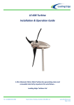
LE-600 Turbine
Installation & Operation Guide
1.55m Diameter Micro Wind Turbine for generating clean and
renewable electricity anywhere the wind blows…
Leading Edge Turbines Ltd
Tel: +44 (0)845 652 0396
Skyrrid Farm, Pontrilas, Hereford. HR2 0BW. UK
www.leturbines.com
Page 1 of 33
Contents
Contents ...................................................................................................................... 2
Introduction ................................................................................................................ 3
Safety Precautions ...................................................................................................... 4
Mechanical Safety Hazards ..................................................................................... 4
Electrical Safety Hazards ......................................................................................... 4
Specifications .............................................................................................................. 5
Tools Required For Assembly ..................................................................................... 6
Mechanical Assembly Procedure ................................................................................ 7
Electrical Installation................................................................................................. 14
Fig-12: Typical ‘Stand-Alone’ Battery Charging Wiring Diagram .......................... 16
Fig-13: Typical ‘Hybrid’ Wind /PV System Wiring Diagram .................................. 17
Fig-14: Typical ‘Grid-Tie’ System Wiring Diagram ................................................ 18
Turbine Operation .................................................................................................... 19
Maintenance ............................................................................................................. 21
Post-installation Checks (to be carried out one month after installation): .......... 21
Annual Maintenance:............................................................................................ 21
After Five years of normal operation: ................................................................... 21
Other Considerations: ........................................................................................... 21
Spares........................................................................................................................ 22
Warranty ................................................................................................................... 23
Disclaimer ................................................................................................................. 24
Tel: +44 (0)845 652 0396
Skyrrid Farm, Pontrilas, Hereford. HR2 0BW. UK
www.leturbines.com
Page 2 of 33
Introduction
Please read this manual thoroughly before attempting to assemble, install or operate your LE-600
small wind turbine. This will assure optimum performance and safety.
Leading Edge Turbines have spent many years developing the ideas and technology behind your
turbine. The LE-600 turbine features an array of innovations and construction techniques as well as
heavy-duty engineering to ensure optimum efficiency and a long operating life.
The LE-600 has been designed to be simple, economic, durable and yield excellent performance.
Your LE-600 turbine features:
•
•
•
•
•
•
•
•
•
•
Innovatively designed axial flux alternator, using neodymium iron boron magnets
A laser-cut, aluminium chassis using 'Yaw-wing' design to ensure responsive yawing
Maintenance-free, low friction bearing arrangements
Extremely quiet injection moulded blades with 'Whispower' geometry and aerofoil design
Long-life yaw pivot slip-rings and wipers
Easy tower-top installation
Simple design for low cost and longevity
Fully marinised using stainless steel fixings and anodised aluminium components
Low mass to help reduce exerted forces and ensure easy installation
Lightweight aluminium design.
The LE-600 has been developed for both land-based and marine environments. Thanks to its unique
design, the LE-600 is not susceptible to corrosion in normal or salt water operating conditions.
Applications include:
•
•
•
•
•
•
•
•
•
•
Tel: +44 (0)845 652 0396
Marine
Remote Homes / Caravans
Street lighting and road signage
Complementary installation with photovoltaic modules for home power
Farm utilities (electric fencing, irrigation, etc.)
Wind-electric water pumping
Cathodic protection
Monitoring sites
Telecommunications
The Developing World
Skyrrid Farm, Pontrilas, Hereford. HR2 0BW. UK
www.leturbines.com
Page 3 of 33
Safety Precautions
Safety must always be your primary concern during the assembly, installation and operation of your
LE-600 turbine. Always be aware of the risks involved with mechanical and electrical installation
work. If in doubt about any issue regarding your turbine, please seek further assistance before
proceeding. Installation of the LE-600 turbine should only be undertaken by suitably competent and
qualified personnel.
Mechanical Safety Hazards
• The main rotor is the most obvious and serious mechanical safety risk. When the turbine is
operating at its rated performance, the blades will be very difficult to see due to the speed
of rotation. Never approach the turbine whilst it is operating. Always shut down the
turbine by activating the stop switch. Ensure that the turbine is installed in a suitable
position where nobody can approach or interfere with the path of the rotor blades.
• Working with tools of any kind can be dangerous. Your LE-600 turbine requires some basic
mechanical assembly with rudimentary hand tools. If you are in any doubt about how to
use these tools correctly, please seek advice from a suitably experienced person.
• Your LE-600 turbine will inevitably be installed upon a tower or other support mount. This
may mean working at height. Always ensure that all personnel in the immediate vicinity
are aware of any lifting / hoisting operations that will be occurring. Check there are no
loose components or tools likely to fall and cause injury during the lifting operation. Where
possible, all assembly work should be completed at ground level. In the case of roof mount
brackets, a suitable fitter should carry out the installation with the appropriate equipment
for working at height.
• Ensure that the batteries are disconnected during the installation procedure.
• Twist the turbine output cables together (to create a short circuit) during the mechanical
installation process. This will prevent the turbine from ‘spinning up’ during the installation.
• Never install the turbine upside down or in any orientation other than that depicted on the
installation instructions.
• Install your turbine during a calm day.
• When performing routine inspection or maintenance, always stop the turbine by activating
the stop switch.
Electrical Safety Hazards
• The LE-600 generates 3-Phase AC voltage from the turbine head and rectified DC voltage
from the rectifier box. Even at low voltages there are inherent risks. Caution should always
be used when connecting LE-600 to the electrical system.
• Ensure that you have followed the cable-sizing chart to ensure that the correct size of
transmission cable has been selected. If a cable of insufficient cross-sectional area is used,
heat may build up in the cables causing a potential fire hazard. A properly sized fuse or
circuit breaker should be used in the cables connected to the battery. This will stop the risk
of short circuit currents. Using cables of insufficient cross-sectional area may also reduce
the power transmission efficiency of the turbine.
• Batteries systems can deliver a serious amount of current. A short circuit in the battery
circuit can lead to hundreds of amps flowing through the battery cables. This will cause a
heat build-up and ultimately an electrical fire. Batteries can explode when shorted. Always
use insulated electrical tools when working on the battery’s electrical connections.
• Batteries are very heavy. Do not attempt to move batteries by yourself. Always use manual
handling tools and an assistant.
• Always keep lead-acid batteries the correct way up. Do not allow the acidic electrolyte to
spill or come into contact with your skin or face. Always follow the manufacturer’s safety
instructions when handling lead-acid batteries.
• Never run the LE-600 'off-load' with the output cables not connected to anything.
Please use common sense when installing and operating your turbine!
Tel: +44 (0)845 652 0396
Skyrrid Farm, Pontrilas, Hereford. HR2 0BW. UK
www.leturbines.com
Page 4 of 33
Specifications
Turbine Name: LE-600 Turbine
Part Number: GA-LETU-009
Nominal Voltage: 12V / 24V / 48V or Grid-tie optimised
Rotor Diameter: 1540 mm
Rated Wind Velocity: 7.2 m/s
Rated Output: 160 Watts
Max Output: 600 Watts (900 Watts in certain applications)
Rated RPM: 550
Start-up Wind Velocity: 2 m/s
Total weight: 19.5 Kg
Tower mount: 60.3 mm Outer Diameter Tube x 3 / 4 mm Wall
Chassis Construction: Aluminium
Rotor Blades (3-off): Glass Reinforced Nylon
Fig-1: Diametric View
Fig-2: Operating Envelope
Fig-3: Energy Conversion
Tel: +44 (0)845 652 0396
Skyrrid Farm, Pontrilas, Hereford. HR2 0BW. UK
www.leturbines.com
Page 5 of 33
Package Contents
Your LE-600 Turbine will arrive containing the components shown below. If any of the components
are missing or damaged, please contact your dealer immediately.
LE300 Chassis: Qty 1
Rotor Blade: Qty 3
Hub Plate: Qty 1
3x
9x
3x
12x
18 x
3x
Nose Cone: Qty 1
User Manual: Qty 1
M6 x16 Cap Heads
M8 x 60 Hex Heads
M6 Washers
M8 Nylock Nuts
M8 Washers
M8 x 12lg Cap Head
Fixings Bag: Qty 1
Tools Required For Assembly
You will require the following tools to assemble your LE-600 Turbine:
•
•
•
•
•
•
•
•
•
Tel: +44 (0)845 652 0396
10mm A/F spanner & 10 mm ratchet (one of each required)
13mm A/F spanner & 13 mm ratchet (one of each required)
A Set of Metric Standard Hexagon Keys
Electrical screw drivers
Power drill
6.5 mm & 3.0 mm diameter twist drill bit, suitable for drilling through steel
Digital multi-meter capable of measuring DC & AC Volts
Tape measure or steel rule
Thread-locking compound (Loctite 243 or similar)
Skyrrid Farm, Pontrilas, Hereford. HR2 0BW. UK
www.leturbines.com
Page 6 of 33
Mechanical Assembly Procedure
1) Unpacking - Inspect the contents of the box and ensure that all items are present and free
from damage. If any of the components are missing or damaged, please contact your
dealer immediately.
2) Check Magnet Rotor & Continuity - Ensure that the main shaft is free turning and does not
scrape or rub as it rotates - see Fig-4. You may feel a slight resistance from the bearings at
this stage. The bearing units used in the magnet rotor assembly are factory lubricated and
sealed for life. It will take approximately 100 hours of normal operation for the bearing
seals to ‘bed-in’ and the lubrication to be distributed correctly around the raceways and
ball cages. During this period you may notice a reduced performance caused by the
additional friction of the bearing seals. In operating temperatures of –10 degrees
Centigrade or lower, this ‘bedding-in’ period will be extended by a further 50 hours of
normal operation. Connect a digital multi-meter to any two of the three output leads
extending from the yaw pivot. With the multi-meter set to detect AC Volts (0-20V), a
voltage should be displayed when the magnet rotor is spun. This voltage will vary with the
speed of rotation. If the magnet rotor rubs, or no voltage is detected whilst turning the
magnet rotor, please contact your dealer immediately.
Warning: The magnet rotor within your LE-600 Turbine is constructed using neodymium iron
boron rare earth magnets which are semi-exposed until the turbine is fully assembled. These are
extremely powerful magnets and can cause injury if not handled with respect. Take care when
working with tools made of ferrous materials (such as spanners and screwdrivers) close to LE-600
alternator. The magnetic forces between ferrous materials and the magnet rotor within the
alternator may be very strong. This may cause a sudden snapping action that can pinch or trap
your fingers or skin.
Fig-4: Checking magnet rotor rotation and coil-disc continuity
Tel: +44 (0)845 652 0396
Skyrrid Farm, Pontrilas, Hereford. HR2 0BW. UK
www.leturbines.com
Page 7 of 33
3) Rotor Blade Assembly - Take the three rotor blades and rotor hub plate. Be careful when
handling the blades, they have VERY SHARP EDGES. Use a 13 mm A/F socket and hexagon
key and three M8 x 60mm long set screws to attach each blade to the hub plate - see Fig-5.
Ensure that the cap head end of the screw is on the rotor hub plate side (thus allowing the
washers and nuts to locate inside of the blades. The blades should all be fixed to the hub
plate on the same side, with the blades in the same orientation. It is important that a
washer is used underneath the anti-vibration nuts. 3 set-screws, 3 washers and 3
anti-vibration nuts should be used on each blade. Tighten the fixings until the blades are
safely secured. Do not over-tighten the nuts as this may damage the blades and fixings.
Fig-5: Attaching the 3 rotor blades to the hub plate
4) Check the Tip Spacing - Although the turbine blades are fitted with location 'keyways', it is
important to check the tip spacing. Lay the assembled rotor blade on a flat surface. Using
a tape measure or long steel rule ensure that the spacing between each tip is equal to
within a tolerance of +/-1.5 mm. Adjust the blades as required. Output performance may
suffer if the blades are inaccurately set - see Fig-6.
Fig-6: Checking tip spacing
Tel: +44 (0)845 652 0396
Skyrrid Farm, Pontrilas, Hereford. HR2 0BW. UK
www.leturbines.com
Page 8 of 33
NOTE: Depending on the type of support structure being utilised for the LE-600, it is sometimes
advisable to fit the main rotor set to the turbine chassis at this stage. However in other
circumstances it will be easier to fit the turbine chassis to the support structure before fitting the
main rotor set. The installer must use judgement as to the best order in which to fit the turbine
together, depending on the merits of the installation and therefore the remaining installation
steps maybe completed in an alternative sequence.
5) Fit the Rotor Blade Assembly - This is done by offering the rotor hub plate against the
drive hub protruding from the front of the chassis. M6 x 16 long cap head screws should
then be used to fix the rotor hub in position using the three unused tapped holes in the
drive shaft. Ensure that all 3 screws are securely tightened and that the rotor blades are
fitted with the flat side of the blade facing towards the magnet rotor. Thread-locking
compound should be used on the screw threads.
Fig-7: Fitting the rotor blades to the chassis
Tel: +44 (0)845 652 0396
Skyrrid Farm, Pontrilas, Hereford. HR2 0BW. UK
www.leturbines.com
Page 9 of 33
6) Check the blade rotation - Once the blades have been fitted and secured to the chassis,
ensure that they rotate freely. Take this opportunity to check that all of the blade and hub
fixings are secure - see Fig-8.
Fig-8: Check blade rotation
Tel: +44 (0)845 652 0396
Skyrrid Farm, Pontrilas, Hereford. HR2 0BW. UK
www.leturbines.com
Page 10 of 33
7) Fit the nose cone - The nose cone can now be fitted to the rotor. This is done by aligning
the mounting slots of the nose cone with the corresponding 'barbs' on the rotor blades.
Once the nose cone is fitted correctly over the blades and runs concentrically, fix it in
position using Qty 3 M8 x 12lg Cap head screws. The screws enter through the mount
holes in the nose cone and align with the 3 tapped holes in the hub plate. Ensure that the
nose cone is secure and true before finally tightening the fixings.
Fig-9: Attach the nose cone
Tel: +44 (0)845 652 0396
Skyrrid Farm, Pontrilas, Hereford. HR2 0BW. UK
www.leturbines.com
Page 11 of 33
8) Prepare the Turbine Mount - If you have purchased a LE-600 mount bracket or tower from
a Leading Edge Turbines’ dealer, then please refer to the separate installation instructions
supplied with the product. If you have sourced your own tower / mount bracket, 7 mm
diameter holes will need to be drilled in order to secure the turbine. These holes should be
drilled 10 mm and 25 mm from the top of the tower / mount bracket and should be
perpendicular to the surface and skewed by 90 degrees. The hole should penetrate both
sides and cross the centre line of the tubular section - see Fig-10.
Fig-10: Drill through top of tower / mount bracket
9) Install the Transmission Cables - When your tower or mount bracket is ready to receive its
turbine, the next stage is to run the cables from the top of the tower to where the rectifier
box / electrical controller and batteries / grid-tie inverter will be located. Follow the table
below to select the correct wire size (cross-sectional area). This will vary depending on
your nominal battery voltage and the distance that the cables will be run. Careful selection
of the cable size is required. It will not only affect the safety of the system, but also the
overall efficiency. A cable of insufficient cable size will cause a voltage drop, wasting the
power that has been generated. The cable sizes listed below have been selected with
efficiency and cost in mind, as it is unlikely that your turbine will be running at full capacity
100% of the time. If in doubt, consult your local electrical supplier. The cable should be
installed in accordance with local electrical regulations and guidelines. If in doubt, use a
local electrical contractor to complete the cable installation.
Warning: If a cable of insufficient cross-sectional area is used, heat will build up in the cables
causing a potential fire hazard. Cable capacities quoted below are based upon ‘Tri-Rated’ cables
(BS6231).
LE-600 Nominal Output
Voltage or GT Variant
12 Volts
24 Volts
48 Volts
GT1 (25-110 Volts)
Tel: +44 (0)845 652 0396
10 Metres
Transmission Distance
25 Metres
50 Metres
16 mm² (3-Core)
25 mm² (3-Core)
50 mm² (3-Core)
4 mm² (3-Core)
10 mm² (3-Core)
16 mm² (3-Core)
1.5 mm² (3-Core)
2.5 mm² (3-Core)
4 mm² (3-Core)
1.5 mm² (3-Core)
2.5 mm² (3-Core)
4 mm² (3-Core)
Skyrrid Farm, Pontrilas, Hereford. HR2 0BW. UK
www.leturbines.com
Page 12 of 33
10) Mount the LE-600 Turbine onto the Support Structure - Ensure that the previously
installed power transmission cables are not yet connected to any batteries and are
‘shorted’ together. This will prevent the turbine from operating during the installation
process. Once this has been done, connect the turbine output cables to the transmission
cables using a connecter supplied by Leading Edge Turbines (supplied separately) or a
suitable terminal block with a minimum rating of 75 Amps (12V), 40 Amps (24V),
25 Amps (48V), 20 Amps (GT1). Offer the turbine up to the support structure and push the
turbine body onto the tower. Ensure that no cables are snagged. Use the M6 x 75
countersunk set-screws along with washers and thread-locking compound to secure the
turbine using the holes previously drilled in the support structure - see Fig-11. Ensure that
the M6 set-screws are securely fastened.
Fig-11: Fitting the turbine onto the support structure
Tel: +44 (0)845 652 0396
Skyrrid Farm, Pontrilas, Hereford. HR2 0BW. UK
www.leturbines.com
Page 13 of 33
Electrical Installation
Please refer to Figs 12 - 14 for appropriate generic wiring diagrams. In a battery charging renewable
energy system, there may be different ways of wiring small wind turbines, photovoltaic panels,
charge controllers and batteries together. This type of system will often expand ‘organically’, but
the following guidelines should be followed:
•
Follow the appropriate electrical code - The electrical wiring of your LE-600 turbine and
associated electrical systems must be done in accordance with national and local electrical
codes and regulations.
•
Do not connect the turbine or batteries during the installation - Ensure that the turbine is
not running or connected to the batteries during the installation or wiring process.
Connect the output cables of the turbine together to prevent the rotor from starting up.
•
Galvanic corrosion of electrical joints - Try to avoid connections between dissimilar
metals. For example, connecting copper and aluminium together will result in galvanic
corrosion of the connection. This will increase the electrical resistance of the connection
(wasting energy), and reduce the mechanical integrity of the joint. Where possible, use a
fluxed solder to make electrical joints.
•
Protect the cables - The power transmission cables must be protected from mechanical
damage and fatigue. Run the cables through an approved conduit / trunking.
•
Cable strain relief - Prevent mechanical strain on the transmission cables running down
the tower from the turbine. Clip the cables to the inside of the tower. Failure to do this will
result in excessive mechanical strain on the cable joints within the slip-ring assembly and
may cause a failure. Cable ties or cable glands are a good way to prevent mechanical strain
on the cables.
•
‘Earth’ the System - The turbine tower should have its own separate earth point. The
negative terminal of the battery bank should also be earthed. This provides protection
against the build-up of static and lightning strikes. The tower should be earthed separately
with its own ground rod if there is a long transmission distance between the tower and
batteries. An appropriate surge arrestor could also be used to help prevent damage to the
battery charging system during a lightning strike. Ensure that the earth cables are of the
same rating as the positive and negative cables.
•
Cable Selection - The cable size table should be used to select the minimum sized cable for
a given transmission distance. Voltage drop in the cable will be improved if a larger cable is
used. We recommend using ‘Tri-Rated’ cable as it should comply with the wiring codes for
your area.
•
Fuses - The turbine and charging circuit should be protected with a suitably rated
‘slow-blow’ DC fuse or DC circuit breaker. Please refer to the table below for the correct
rating. The fuse or breaker should be positioned between the turbine and batteries (on the
positive cable). If a stop switch is used (recommended) the fuse should be positioned
between the switch and the batteries.
LE-600 Nominal
Output Voltage
12 V
24 V
48 V
GT1
Tel: +44 (0)845 652 0396
DC Fuse / DC Circuit Breaker Rating
60 Amp
30 Amp
20 Amp
16 Amp
Skyrrid Farm, Pontrilas, Hereford. HR2 0BW. UK
www.leturbines.com
Page 14 of 33
•
Run / Stop Switch - A simple switch arrangement can provide a safe and easy way of
stopping the turbine during high winds or for maintenance. Leading Edge Turbines can
supply a switch which is best for this purpose. As the switch is thrown, the batteries are
disconnected and the turbine is ‘shorted’ reducing the rotor to a slow rotation. Refer to
the generic wiring diagrams.
•
Charge Controllers - Two LE-DL-300 Diversion Charge Controllers are recommended to
manage the power output from the turbine to the batteries. These diversion charge
controllers operate by increasingly switching output to a dump load once the batteries
begin to reach high voltages. The dump load consumes the ‘excess’ power from the
turbine. This means that the turbine’s power output is always utilised whether the
batteries are fully charged or not. Larger capacity battery banks will be able to store more
energy and so the dump load will be used less. Do not use a photovoltaic type
charge controller with your LE-600 turbine. For hybrid or more complex systems, we
recommend that a 45 A or 60 A Diversion Controller is utilised together with a separate
dump load.
•
‘Hybrid’ Systems - The LE-600 Turbine can be used in parallel with PV panels. We
recommend that the PV panels are wired independently with a separate charge controller
specifically designed for use with PV panels and connected in parallel with the battery
bank - see Fig-13. For hybrid or more complex systems, we recommend that a 45 A or 60 A
Diversion Controller is utilised together with a separate dump load.
•
Use of Grid-tie Inverters - It is possible to connect your LE-600 to a grid-tie (grid connect)
inverter. It is recommended that only grid-tie inverters supplied by Leading Edge Turbines
are used to ensure that an appropriate MPPT curve has been programmed.
Please refer to the following wiring diagrams as a guide.
Tel: +44 (0)845 652 0396
Skyrrid Farm, Pontrilas, Hereford. HR2 0BW. UK
www.leturbines.com
Page 15 of 33
LE-600
TURBINE
(PN: GA-LETU-009)
TOWER
OR
SUPPORT
STRUCTURE
EARTH GROUND
SEE RUN / STOP SWITCH
USER MANUAL FOR
DETAILED INSTRUCTIONS
RUN / STOP
SWITCH BOX
(REQUIRED)
PN: GA-CTRL-008A
CHASSIS GROUND
RECTIFIER BOX
(SUPPLIED)
A
AMMETER
(OPTIONAL)
FUSE OR BREAKER
(RECOMMENDED)
BATTERY DISCONNECT
(OPTIONAL)
CHASSIS GROUND
+
-
+
-
+
-
+
-
BATTERY BANK
(WIRED TO APPROPRIATE
CAPACITY & VOLTAGE)
LE-DL-300
CONTROLLER
(QTY 2 REQUIRED)
PN: GA-CTRL-001A
SEE LE-DL-300
USER MANUAL FOR
DETAILED INSTRUCTIONS
Fig-12: Typical ‘Stand-Alone’ Battery Charging Wiring Diagram
Tel: +44 (0)845 652 0396
Skyrrid Farm, Pontrilas, Hereford. HR2 0BW. UK
www.leturbines.com
Page 16 of 33
LE-600
TURBINE
(PN: GA-LETU-009)
TOWER
OR
SUPPORT
STRUCTURE
EARTH GROUND
PV
PANEL
ARRAY
(400W MAX)
SEE RUN / STOP SWITCH
USER MANUAL FOR
DETAILED INSTRUCTIONS
RUN / STOP
SWITCH BOX
(REQUIRED)
PN: GA-CTRL-008A
CHASSIS GROUND
RECTIFIER BOX
(SUPPLIED)
A
AMMETER
(OPTIONAL)
FUSE OR BREAKER
(RECOMMENDED)
CHASSIS GROUND
A
AMMETER
(OPTIONAL)
BATTERY DISCONNECT
(OPTIONAL)
FUSE OR BREAKER
(RECOMMENDED)
BATTERY DISCONNECT
(OPTIONAL)
CHASSIS GROUND
+
-
+
-
+
-
+
-
BATTERY BANK
(WIRED TO APPROPRIATE
CAPACITY & VOLTAGE)
TRI-STAR 45
(REQUIRED)
PN: GA-CTRL-002
1000W DUMP LOAD
(REQUIRED)
PN: GA-CTRL-007
Fig-13: Typical ‘Hybrid’ Wind /PV System Wiring Diagram
Tel: +44 (0)845 652 0396
Skyrrid Farm, Pontrilas, Hereford. HR2 0BW. UK
www.leturbines.com
Page 17 of 33
LE-600
TURBINE
(PN: GA-LETU-009)
TOWER
OR
SUPPORT
STRUCTURE
EARTH GROUND
SEE RUN / STOP SWITCH
USER MANUAL FOR
DETAILED INSTRUCTIONS
RUN / STOP
SWITCH BOX
(REQUIRED)
PN: GA-CTRL-008A
CHASSIS GROUND
RECTIFIER BOX
(SUPPLIED)
A
AMMETER
(OPTIONAL)
FUSE OR BREAKER
(RECOMMENDED)
BATTERY DISCONNECT
(OPTIONAL)
CHASSIS GROUND
OVER-VOLTAGE
PROTECTION
(SUPPLIED)
OVER-VOLTAGE
PROTECTION
MASTERVOLT
WINDMASTER 500
GRID-TIE INVERTER
230VAC
50HZ GRID
Fig-14: Typical ‘Grid-tie’ System Wiring Diagram
Tel: +44 (0)845 652 0396
Skyrrid Farm, Pontrilas, Hereford. HR2 0BW. UK
www.leturbines.com
Page 18 of 33
Turbine Operation
The LE-600 Turbine is based on a simple design for ease of installation and reliable operation. You
may notice the following behaviour during normal operation:
•
Cut-in - The turbine will not begin to charge the batteries until the rotor is spinning at
approximately 290 RPM. Whilst operating below this speed, the turbine will be ‘off-load’
and freewheeling. Once the turbine output voltage becomes equal to the nominal battery
voltage (at around 290 RPM), the turbine will come ‘on-load’ and begin to deliver current
to the batteries. During the off-load stages of rotation, the blades will rotate very freely.
This allows the rotor to build up speed and allows aerodynamic lift to be generated by the
blades.
•
Normal Operation - Once the rotor is spinning more than 290 RPM, current will be
delivered to the batteries. As the rotor speed increases, so too will the current and
voltage. Excessive wind speed may increase the battery voltage to a high level. Once this
happens the diversion charge controller will recognise that the battery voltage is too high
and begin 'dumping' power to the heater module.
•
Charge Regulation - Once the charge controller has switched over to the dump load, the
turbine will no longer be charging the batteries. Instead the power from the turbine will be
delivered to the dump load (usually a resistive heater element). The battery voltage will
begin to drop to normal levels during the regulation period. Once the battery voltage is
back within acceptable limits, the charge controller will switch the turbine output back to
the batteries. Refer to the Charge Controller User Manual for specific operational
instructions. This arrangement is more effective than stop/starting the turbine incessantly.
•
Shut Down - By activating the stop switch, the output from the cables of the turbine are
‘shorted’ together. This effectively puts an infinite load on the generator causing the
turbine to stall. When the stop switch is activated, the turbine may still rotate slowly
during high winds, but the rotor blades will not be able to build up any significant speed. It
is not recommended that the stop switch is activated whilst the rotor is spinning at high
speed. This sudden braking action will stress the blades and other components. Only
activate the stop switch during a ‘lull’ when the rotor is not spinning excessively fast.
Very high winds - Due to the configuration of the low friction, high efficiency alternator,
the electromagnetic braking effect is not as strong as with more conventionally designed
turbines. In certain high wind conditions, the rotor can overcome the electromagnetic
braking, which allows high currents to be produced in the stator coils. If this situation
occurs with the wind driving the braked alternator for prolonged periods, damage to the
turbine will occur. Therefore the braking switch should only be used to slow the unit prior
to manually / mechanically tethering the turbine in during very high winds.
•
Tel: +44 (0)845 652 0396
High Winds - Every effort has been taken to ensure that the LE-600 will withstand the
forces exerted by strong winds. However, the raw power in high winds is immense and the
stresses placed upon the turbine are magnified by gusty and turbulent conditions. Where
possible the turbine should be shut down and tethered in advance of particularly strong
winds (60+ MPH) and storm conditions. This will decrease the wear and tear on the
machine and will help to avoid a failure. Protect the turbine from extreme winds as you
would protect other items of your property.
Skyrrid Farm, Pontrilas, Hereford. HR2 0BW. UK
www.leturbines.com
Page 19 of 33
•
Grid-tie Applications - When connected to a grid-tie inverter, the LE-600 will operate in
much the same manner as when it is charging batteries (except for the use of dump loads).
It is important that the grid-tie inverter characteristics are matched to the power curve of
the turbine to ensure optimum performance. An appropriate electrical interface may also
be required depending on the inverter equipment being used. It is generally only
recommended that Leading Edge Turbines approved and programmed inverters be used
with the LE-600. Refer to your Leading Edge Turbines’ dealer for more information on this.
Note: Never allow the turbine to run off-load with no connection to a battery bank or grid-tie
inverter. Doing so will allow open-circuit voltages to be generated by the turbine. These voltages
may be dangerous and may damage the stator coils within the turbine.
Tel: +44 (0)845 652 0396
Skyrrid Farm, Pontrilas, Hereford. HR2 0BW. UK
www.leturbines.com
Page 20 of 33
Maintenance
Please follow the preventive maintenance programme listed below. This will ensure that the
turbine operates reliably and safely with good efficiency.
Always shut down the turbine before attempting to carry out maintenance.
Post-installation Checks (to be carried out one month after installation):
• Check that the tower mount pins are secure and have not worked loose. Adjust if required.
• Ensure that the rotor hub is still securely fitted.
• Ensure that the rotor blades rotate freely.
• Monitor the output. Ensure that the turbine and charge controller are functioning
correctly.
Annual Maintenance:
• Inspect the tower / support structure.
• Remove the turbine from its installation to a suitable workbench.
• Remove the rotor blade assembly
• Inspect the edges of the rotor blades for damage such as dents or chips. The blades will
become unbalanced if they are damaged. This will cause vibration, noise and poor
performance. If many dents have occurred along the edges of the blades, a new set of
rotor blades should be fitted (part numbers available in the Spares section).
• Inspect the roots of the blades (attachment tabs) for signs of stress cracking or fatigue. A
new set of rotor blades should be fitted if any cracks of fractures have occurred (part
numbers available in the Spares section).
• Remove any build-up of dirt and debris from the rotor blades using a mild detergent and
warm water.
• Check the blade hub fixings for tightness.
• Carefully remove the yaw mount bracket by unscrewing the 4 connection screws from the
sides of the LE-600 chassis. Inspect the slip rings and wipers for obvious signs of wear.
Replace the wipers if required (part numbers available in the Spares section). Reassemble
the yaw pivot carefully (do not pinch any cables).
• Check that all electrical connections are sound and free from corrosion.
• Generally ensure that the turbine is in good working condition and is safe for continued
use.
After five years of normal operation:
• We recommend that the rotor bearings and rotor blades should be replaced after five
years of continuous operation. This will ensure that the turbine’s performance and safety
are not compromised.
Other Considerations:
• The equipment used in the charging system (batteries, charge controller, PV panels,
invertors, etc.) should be maintained according to the instructions published by the
relevant manufacturer.
• Where lead-acid batteries are used, it is especially important that they are maintained
carefully. Failure to do so will result in the batteries being rendered useless within a short
period of time.
Tel: +44 (0)845 652 0396
Skyrrid Farm, Pontrilas, Hereford. HR2 0BW. UK
www.leturbines.com
Page 21 of 33
Spares
The following components may need to be replaced during the service life of your LE-600 turbine.
Please contact your nearest Leading Edge Turbines’ Dealer, and quote the part numbers listed
below.
Rotor Blade (qty 3 matched set):
Slip Ring Wiper (qty 1):
Slip Ring (qty 1):
Coil-disc (12 VDC):
Coil-disc (24 VDC):
Coil-disc (48 VDC):
Coil-disc (GT1):
Yaw Bearings & Housing:
Rotor Bearings & Housing:
DP-LETU-041G
DP-LETU-185
DP-LETU-140
SA-LETU-005/12V
SA-LETU-005/24V
SA-LETU-005 /48V
SA-LETU-005 /GT1
DP-LETU-184
DP-LETU-160
Run / Stop Switch Box:
LE-DL-600 Diversion Controller:
GA-CTRL-008A
GA-CTRL-001A
Tel: +44 (0)845 652 0396
Skyrrid Farm, Pontrilas, Hereford. HR2 0BW. UK
www.leturbines.com
Page 22 of 33
Warranty
Your LE-600 Turbine carries a two-year warranty from the original purchase date. Please keep your
receipt as proof.
During the warranty period any component found to be defective in material or workmanship will,
at the discretion of Leading Edge Turbines, be replaced or repaired at no charge.
For minor component failures, replacements may be sent directly to the customer / dealer for
replacement. For more serious defects we may suggest a ‘return-to-base’ arrangement for
replacement or repair. In all cases Leading Edge Turbines will take reasonable action to ensure
customer satisfaction. You will always receive a warm, courteous service in or out of your warranty
period.
Your turbine must be installed and operated in accordance with this guide and local electricity
codes. Failure to do so will result in this warranty becoming null and void. Any unauthorised
modifications to the turbine design will void the warranty and may compromise the safety of the
machine.
What is not covered by your warranty?
If your turbine is commissioned by Leading Edge Turbines, the following are excluded from the
warranty
•
•
•
•
•
•
•
•
•
•
•
•
•
Damage caused by the neglect of periodic maintenance in the manner recommended.
Damage caused by repair or maintenance performed using methods not specified by
Leading Edge Turbines or by non-authorised dealers of Leading Edge Turbines’ products.
Damaged caused by the use of non-genuine parts, or from the use of liquid agents or
lubricants in or on the turbine, tower or control equipment.
Damage caused by operating the turbine in conditions outside of those specified in the
Owner’s Guide – including, but not limited to, allowing the turbine to run off-load.
Damage caused by modifications to the turbine, tower or control equipment not approved
by Leading Edge Turbines.
Damage caused to the turbine, tower and control equipment by improper storage or
transport.
Damage caused by lightning strikes.
Damage due to extremely high winds and storm conditions (60 mph+).
Damage caused by flying debris.
Aesthetic phenomena that do not affect performance.
Damage caused by unsatisfactory installation of the turbine, tower and/or control
equipment.
Damage caused by unsatisfactory tower / support structure design.
Damage caused by incorrect connection to external electrical equipment, or failure to
observe current regulations concerning connection to external electrical networks,
equipment or any other devices.
If you should experience a problem with your turbine, your first ‘port-of-call’ should be the reseller
or installer from whom you purchased the product. They will be able to resolve the problem quickly
and efficiently. If you are unable to contact the original reseller, then please contact us directly.
Please quote the serial number of your turbine when dealing with warranty issues. The
serial number can be found on the nameplate positioned on the underside of the chassis.
Tel: +44 (0)845 652 0396
Skyrrid Farm, Pontrilas, Hereford. HR2 0BW. UK
www.leturbines.com
Page 23 of 33
Disclaimer
•
•
•
•
•
All specifications are subject to change without prior notice.
The information given in this User Manual is believed to be accurate and reliable.
Leading Edge Turbines assumes no responsibility for omissions or inaccuracies.
The user of this information and product assumes full responsibility and risk.
The LE-600 turbine is a source of electrical power. It must be installed in accordance with
local building and electrical regulations. Consult your local planning (zoning) office for
details.
The LE-600 turbine has moving parts that may cause injury due to poor installation and
unsafe operation. Leading Edge Turbines assumes no responsibility for problems caused by
unsafe or unsatisfactory installation or operation.
Designed & Manufactured in the UK by:
Leading Edge Turbines Ltd
Skyrrid Farm,
Pontrilas,
Hereford.
HR2 0BW
Tel: +44 (0)845 652 0396
www.leturbines.com
Compliant with
EN BS 61400-2: Safety of Small Wind Turbines
Tel: +44 (0)845 652 0396
Skyrrid Farm, Pontrilas, Hereford. HR2 0BW. UK
www.leturbines.com
Page 24 of 33
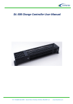
Appendix 1: LE-DL-300 Charge Controller User Manual
Tel: +44 (0)845 652 0396
Skyrrid Farm, Pontrilas, Hereford. HR2 0BW. UK
www.leturbines.com
Page 25 of 33
Introduction
Please read this manual thoroughly before attempting to assemble, install or operate your
LE-DL-300 Charge Controller. This will assure optimum performance and safety.
The LE-DL-300 Series Dump Controller and Load is an integrated solution designed to prevent 12 or
24 Volt batteries from overcharging. It is designed to be used with small wind systems operating a
LE-600 turbine. Compact and easy to install, the LE-DL-300 was developed especially for the LE-600
turbine. It incorporates a 300 Watt resistor / heater and controller board in a stout powder
coated steel enclosure. For the LE-600 wind turbine, two LE-DL-300s work in parallel.
Operation & Specification
As the LE-600 Turbine charges the batteries, the State of Charge (SOC) and battery voltage will rise.
Once the batteries reach full capacity, the dump load controller begins to bleed power from the
turbine into the dump load. This energy is then dissipated as heat into the surrounding
environment. More or less power is diverted to the dump load according to how much power is
being supplied to the battery and also in relation to the state of charge of the battery.
The LE-DL-300 Features:
PWM (Pulse Width Modulation) for highest charging performance without flicker
Selectable three-stage charging or over-voltage protection mode
Selectable for sealed or flooded batteries using jumpers
Power, 12 Volt version, DL300-12:
Recommend fuse or circuit breaker: 30 Amps
Integrated load resistor: 300 Watt, wire wound
Quiescent current when not load dumping: 2.6 mA @ 12 Volts
Power, 24 Volt version, DL300-24:
Recommend fuse or circuit breaker: 15 Amps
Integrated load resistor: 300 Watt, wire wound
Quiescent current when not load dumping: 3.0 mA @ 24 Volts
Connections:
#10-32 brass screws for V+ and VTwo 1/2” / 3/4” concentric NPT knockouts and two 1/2” NPT knockouts
Mounting:
Mounts to vertical concrete, metal, drywall, or other non-flammable surfaces.
Uses four #10 screws
Body sits 19 mm out from wall
Enclosure suitable for indoor mounting
Weight and Dimensions:
Dimensions: 88 mm wide, 95 mm tall, 470 mm long (3.375 x 3.75 x 18.5 in)
Weight: 1.94 Kg (4.28 pounds)
Shipping Dimensions: 102 mm wide, 108 mm tall, 508 mm long (4.0 x 4.25 x 20 in)
Shipping Weight: 2.15 Kg (4.75 pounds)
Materials:
Enclosure: 18-gauge mild steel, powder coated black
Circuit board: FR-4, 1.6 mm (0.062 in), double sided, plated through holes, solder mask, silk screen,
gold plating
Hardware: stainless steel, zinc plated steel, aluminium, and Nylon
Tel: +44 (0)845 652 0396
Skyrrid Farm, Pontrilas, Hereford. HR2 0BW. UK
www.leturbines.com
Page 26 of 33
Safety Precautions
Safety must always be your primary concern during the assembly, installation and operation of your
LE-600 turbine and DL300 Charge Controller. Always be aware of the risks involved with mechanical
and electrical installation work. If in doubt about any issue regarding your turbine system, please
seek further assistance before proceeding.
Mechanical Safety Hazards:
Whilst installing the DL300 Charge Controller or when performing routine inspection or
maintenance, always stop the turbine by activating a stop switch.
Electrical Safety Hazards:
The LE-600 generates rectified DC voltage and the LE-DL-300 controller also operates at these
voltages. Even at these low voltages there are inherent risks. Caution should always be used when
connecting an LE-600 Turbine or LE-DL-300 controller to the electrical system.
Make sure that you have followed the cable-sizing guidelines so that that the correct size of cable
has been selected. If a cable of insufficient cross-sectional area is used at any point in the electrical
system, heat will build up in the cables causing a potential fire hazard. A properly sized fuse or
circuit breaker should be used in the cables connected to the battery. This will stop the risk of short
circuit currents.
Batteries used in renewable energy systems can deliver a serious amount of current. A short circuit
in the battery circuit can lead to hundreds of amps flowing through the battery cables. This will
cause a heat build-up and ultimately an electrical fire. Batteries are also susceptible to explode
when shorted. Always use insulated electrical tools when working on the battery’s electrical
connections.
Batteries are very heavy. Do not attempt to move batteries by yourself. Always use manual
handling tools and an assistant.
Always keep lead-acid batteries the correct way up. Do not allow the acidic electrolyte to spill or
come into contact with your skin or face. Always follow the manufacturer’s safety instructions
when handling lead-acid batteries.
Please use common sense when installing and operating your turbine and LE-DL-300 Charge
Controller
Tel: +44 (0)845 652 0396
Skyrrid Farm, Pontrilas, Hereford. HR2 0BW. UK
www.leturbines.com
Page 27 of 33
Electrical Installation
Please refer to electrical schematic for appropriate generic wiring diagrams. In a battery charging
renewable energy system, there may be different ways of wiring small wind turbines, photovoltaic
panels, charge controllers and batteries together. This type of system will often expand
‘organically’, but the following guidelines should be followed:
Location – The LE-DL-300 controller should be mounted in an adequately ventilated area, which is
not exposed to direct moisture or spray. The dump load elements become hot during normal
operation and should not be covered or blocked.
Gel or Flooded Batteries – An electrical jumper needs to be configured in order to make the
controller more suitable for use with 'Flooded' or 'Gel' batteries. A jumper (supplied) should be
applied to pins labelled '2.2' when the LE-DL-300 is to be used with flooded batteries. When the
LE-DL-300 is to be used with Gel batteries, no jumper should be applied to pins '2.2'. In any
circumstance, no jumper should be applied to pins '2.1'.
Use the correct voltage controller – A 12 V DL300 controller should only be used on a 12 V battery
system. A 24 V DL300 controller should only be used on a 24 V battery system. Do not interchange.
Follow the appropriate electrical code - The electrical wiring of your LE-600 and associated
electrical systems must be done in accordance with national and local electrical codes and
regulations.
Do not connect the turbine or batteries during the installation - Ensure that the turbine is not
running or connected to the batteries during the installation or wiring process. Connect the output
cables of the turbine together to prevent the rotor from starting up.
Galvanic corrosion of electrical joints - Try to avoid connections between dissimilar metals. For
example, connecting copper and aluminium together will result in galvanic corrosion of the
connection. This will increase the electrical resistance of the connection (wasting energy), and
reduce the mechanical integrity of the joint. Where possible, use a fluxed solder to make electrical
joints.
Protect the cables - The power transmission cables must be protected from mechanical damage
and fatigue. Run the cables through an approved conduit / trunking.
Cable strain relief - Prevent mechanical strain on all cables. Cable ties or cable glands are a good
way to prevent mechanical strain on the cables.
Fuses - The LE-DL-300 controller should be protected with a suitably rated ‘slow-blow’ DC fuse or
DC circuit breaker. Please refer to the table below for the correct rating. The fuse or breaker should
be positioned between the DL300 and batteries (on the positive cable)
Nominal Voltage
12V
24V
Tel: +44 (0)845 652 0396
DC Fuse / DC Circuit Breaker Rating
30 Amp
15 Amp
Skyrrid Farm, Pontrilas, Hereford. HR2 0BW. UK
www.leturbines.com
Page 28 of 33
Jumper Positions of DL300 Controller
Electrical Jumper
An electrical jumper needs to be configured in order to make the controller more suitable for use
with 'Flooded' or 'Gel' batteries. A jumper (supplied) should be applied to pins labelled '2.2' when
the LE-DL-300 is to be used with flooded batteries. When the LE-DL-300 is to be used with Gel
batteries, no jumper should be applied to pins '2.2'. In any circumstance, no jumper should be
applied to pins '2.1'.
Tel: +44 (0)845 652 0396
Skyrrid Farm, Pontrilas, Hereford. HR2 0BW. UK
www.leturbines.com
Page 29 of 33
Appendix 2: Run / Stop Switch User Manual
Tel: +44 (0)845 652 0396
Skyrrid Farm, Pontrilas, Hereford. HR2 0BW. UK
www.leturbines.com
Page 30 of 33
Introduction
Please read this manual thoroughly before attempting to assemble, install or operate your
Universal Run / Stop Switch. This will assure optimum performance and safety.
The Universal Run / Stop Switch is a solution designed to allow the user to brake dynamically an
LE-300, LE-600 or LE-2000 turbine at will. This is achieved by disconnecting the power output of the
turbine from the relevant load and diverting it to a short circuit which then applies the dynamic
braking effect on the permanent magnet alternator of the turbine. This will bring the turbine to a
near stop for maintenance, or to allow the turbine to ride out high winds and storms safely.
The Universal Run / Stop Switch can be used with turbines of different manufacture as long as the
relevant turbine has the following characteristics:
3-phase Wild AC not exceeding 500 V & 16 A
Wild DC not exceeding 150 V & 10 A
Mechanically and electrically capable of dynamic braking
Operation & Specification
The Universal Run / Stop Switch should ideally be operated during low speeds as repeated use at
high speeds may cause damage to the turbine head (it was not designed to withstand repeated
dynamic braking operations).
The switch has 2 positions:
Position 1: Turbine 'Stop' position. The turbine is dynamically braked and may be seen to rotate
very slowly.
Position 2: Turbine 'Run' position. The turbine output is allowed to flow straight through the switch
to the relevant output.
Safety Precautions
Safety must always be your primary concern during the assembly, installation and operation of your
turbine and other associated equipment. Always be aware of the risks involved with mechanical
and electrical installation work. If in doubt about any issue regarding your turbine system, please
seek further assistance before proceeding.
Mechanical Safety Hazards:
Whilst installing the Universal Run / Stop Switch, ensure that the turbine is suitable restrained and
not allowed to operate during the installation.
Electrical Safety Hazards:
The LE-600 generates rectified DC voltage and the Universal Run / Stop Switch also operates at
these voltages. Even at these low voltages there are inherent risks. Caution should always be used
when connecting LE-600 or other equipment to the electrical system.
The LE-600 & LE-2000 can generate high voltage AC, and the Universal Run / Stop Switch also
operates at these voltages. Such voltages bring with them significant risks. Caution should always
be used when connecting an LE-2000 or other equipment to the electrical system.
Tel: +44 (0)845 652 0396
Skyrrid Farm, Pontrilas, Hereford. HR2 0BW. UK
www.leturbines.com
Page 31 of 33
Ensure that you have followed the cable-sizing guidelines in order to select the correct size of cable.
If a cable of insufficient cross-sectional area is used at any point in the electrical system, heat will
build up in the cables causing a potential fire hazard. A properly-sized fuse or circuit breaker should
be used in the cables connected to the battery. This will stop the risk of short circuit currents.
Batteries used in renewable energy systems can deliver a serious amount of current. A shorting of
the battery circuit can lead to hundreds of amps flowing through the battery cables. This will cause
a heat build-up and ultimately an electrical fire. Batteries are also susceptible to explode when
shorted. Always use insulated electrical tools when working on the battery’s electrical connections.
Batteries are very heavy. Do not attempt to move batteries by yourself. Always use manual
handling tools and an assistant. Always keep lead-acid batteries the correct way up. Do not allow
the acidic electrolyte to spill or come into contact with your skin or face. Always follow the
manufacturer’s safety instructions when handling lead-acid batteries.
Ensure that the Universal Run / Stop switch is correctly wired as per these instructions and wiring
schematics. Incorrect wiring may lead to a short circuit being placed across the batteries which can
lead to fire or explosion.
Please use common sense when installing and operating your turbine and associated equipment.
Installation
Please refer to electrical schematic for appropriate generic wiring diagrams.
The Universal Run / Stop Switch can either be mounted in the enclosure box (supplied), which, in
turn, can be mounted on an internal panel, or the switch can be integrated into an existing panel. If
the unit is to be integrated into an existing panel, a suitable cut-out, as detailed on the wiring
diagram will need to be made.
1
5
Switch Wiring for LE-300 Turbine:
Tel: +44 (0)845 652 0396
Skyrrid Farm, Pontrilas, Hereford. HR2 0BW. UK
www.leturbines.com
Page 32 of 33
Switch Wiring for LE-600 & LE-2000 Turbine:
1
5
9
Panel Cut-out for Integrated Installation:
Tel: +44 (0)845 652 0396
Skyrrid Farm, Pontrilas, Hereford. HR2 0BW. UK
www.leturbines.com
Page 33 of 33