1
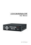
4-Ch H.264 Digital Video Recorder DVR-462 User’s Manual Version 1.0 Copyright Copyright (C) 2010 PLANET Technology Corp. All rights reserved. The products and programs described in this User’s Manual are licensed products of PLANET Technology, This User’s Manual contains proprietary information protected by copyright, and this User’s Manual and all accompanying hardware, software, and documentation are copyrighted. No part of this User’s Manual may be copied, photocopied, reproduced, translated, or reduced to any electronic medium or machine-readable form by any means by electronic or mechanical. Including photocopying, recording, or information storage and retrieval systems, for any purpose other than the purchaser's personal use, and without the prior express written permission of PLANET Technology. Disclaimer PLANET Technology does not warrant that the hardware will work properly in all environments and applications, and makes no warranty and representation, either implied or expressed, with respect to the quality, performance, merchantability, or fitness for a particular purpose. PLANET has made every effort to ensure that this User’s Manual is accurate; PLANET disclaims liability for any inaccuracies or omissions that may have occurred. Information in this User’s Manual is subject to change without notice and does not represent a commitment on the part of PLANET. PLANET assumes no responsibility for any inaccuracies that may be contained in this User’s Manual. PLANET makes no commitment to update or keep current the information in this User’s Manual, and reserves the right to make improvements to this User’s Manual and/or to the products described in this User’s Manual, at any time without notice. If you find information in this manual that is incorrect, misleading, or incomplete, we would appreciate your comments and suggestions. FCC This equipment has been tested and found to comply with Part 15 of the FCC Rules. Operation is subject to the following two conditions: (1) This device may not cause harmful interference (2) This device must accept any interference received. Including interference that may cause undesired operation. CE This equipment is in compliance with the requirements of the following regulations: EN 55 022: CLASS B WEEE regulation To avoid the potential effects on the environment and human health as a result of the presence of hazardous substances in electrical and electronic equipment, end users of electrical and electronic equipment should understand the meaning of the crossed-out wheeled bin symbol. Do not dispose of WEEE as unsorted municipal waste and have to collect such WEEE separately. I Energy Saving Note of the Device This power required device does not support Stand by mode operation. For energy saving, please remove the DC-plug or push the hardware Power Switch to OFF position to disconnect the device from the power circuit. Without remove the DC-plug or switch off the device, the device will still consuming power from the power circuit. In the view of Saving the Energy and reduce the unnecessary power consuming, it is strongly suggested to switch off or remove the DC-plug for the device if this device is not intended to be active. Trademarks The PLANET logo is a trademark of PLANET Technology. This documentation may refer to numerous hardware and software products by their trade names. In most, if not all cases, these designations are claimed as trademarks or registered trademarks by their respective companies. Revision User’s Manual for PLANET 4-Ch H.264 Digital Video Recorder Model: DVR-462 Rev: 1.0 (April, 2010) Part No. EM-DVR462 II This symbol is intended to alert the user to the presence of unprotected “Dangerous voltage" within the product's enclosure that may be strong enough to cause a risk of electric shock. This symbol is intended to alert the user to the presence of important operating and maintenance (servicing) instructions in the literature accompanying the appliance. WARNING !!! TO REDUCE THE RISK OF FIRE OR ELECTRIC SHOCK, DO NOT EXPOSE THIS APPLIANCE TO RAIN OR MOISTURE. All the safety and operating instructions must be read before the unit is operated. • Make sure to switch the power off before you install the DVR. • There is the danger of an electric shock if the DVR is opened by an unqualified service engineer or installer. • Avoid using the DVR outside of the reference temperature and humidity indicated in the specification. • Avoid exposing the DVR to violent movement or vibration. • Do not use or store the DVR in direct sunlight or near to any source of heat. • Do not place any object into the holes used for air circulation. • Always use the DVR in a well ventilated location to prevent overheating. • Risk of explosion if battery is replaced by an incorrect type. • Dispose of used batteries according to the instructions. III TABLE OF CONTENTS Chapter 1 FEATURES ...................................................................................................................... 1 Chapter 2 PACKING DETAIL ............................................................................................................ 2 Chapter 3 LOCATION AND CONTROL ............................................................................................ 3 3.1 Front Panel Controls ..............................................................................................................3 3.2 Real Panel Connectors ...........................................................................................................4 3.3 Remote Control ......................................................................................................................5 3.4 Mouse Control........................................................................................................................8 3.5 Playback Mode.....................................................................................................................10 3.6 PTZ Mode ............................................................................................................................ 11 Chapter 4 INSTALLATION .............................................................................................................. 13 4.1 System Configuration ..........................................................................................................13 4.2 Hard Disk Installation ..........................................................................................................14 Chapter 5 BASIC OPERATION and MENU SETUP ....................................................................... 16 5.1 Main Menu Setup.................................................................................................................16 5.2 Record Setup ........................................................................................................................17 5.3 Event Setup ..........................................................................................................................19 5.4 Schedule Setup.....................................................................................................................21 5.5 Camera Setup .......................................................................................................................23 5.6 Account Setup ......................................................................................................................24 5.7 Network Setup .....................................................................................................................26 5.8 PTZ & RS-485 Setup ........................................................................錯誤! 尚未定義書籤。 5.9 System Setup........................................................................................................................33 5.10 Utility Setup .......................................................................................................................39 5.11 Diagnostic ..........................................................................................................................40 Chapter 6 SEARCH & BACKUP ..................................................................................................... 41 6.1 Search Setup.........................................................................................................................41 6.2 Backup Setup .......................................................................................................................44 Chapter 7 iCMS Installation and Usage.......................................................................................... 45 7.1 iCMS Installation .................................................................................................................45 7.2 iCMS Login and Environment.............................................................................................47 7.3 Groups & Events..................................................................................................................49 7.4 View DVR/ Group List ........................................................................................................49 7.5 Event View ...........................................................................................................................50 7.6 Local PC Information and Control.......................................................................................50 7.7 Main Display........................................................................................................................51 7.8 Audio Control.......................................................................................................................51 7.9 eMaps ...................................................................................................................................52 7.10 PTZ Control .......................................................................................................................53 7.11 Operation Bar .....................................................................................................................54 7.12 User administration ............................................................................................................55 IV 7.13 DVR Connection Information Setup..................................................................................56 7.14 Group Administration ........................................................................................................56 7.15 eMap Setup ........................................................................................................................58 7.16 Remote-Site Playback ........................................................................................................58 7.17 HDD Playback ...................................................................................................................60 7.18 File Playback......................................................................................................................61 7.19 Event Playback...................................................................................................................62 7.20 Snapshot Data ....................................................................................................................63 7.21 Recording Data ..................................................................................................................63 Chapter 8 NETWORK SURVEILLANCE......................................................................................... 64 8.1 AP Software Installation and Setup......................................................................................64 8.2 AP Software Operation ........................................................................................................65 Chapter 9 Mobile Application .......................................................................................................... 68 9.1 For Symbian System ............................................................................................................68 9.2 For Windows Mobile System...............................................................................................74 Appendix A: Product Specification .................................................................................................. 78 The author assumes no responsibility for any errors or omissions that may appear in this document nor does the author make a commitment to update the information herein. V Chapter 1 FEATURES z z z z z z z z z z z z z z z z z z z z Two USB ports (for mouse usage and backup). Dual streaming enhances the speed of network transmission Built-in VGA output up to 1024x768 resolution Individual setup of resolution, frame rate and video quality for each channel Still image snapshot AVI converter with time stamp H.264 compression ideal for saving HDD space Real time live display Live display, record, backup, playback and network access simultaneously Picture-in-picture monitoring and 2X to 8X ditital zoom display Control Methods: front panel, USB mouse, IR remote controller, client viewer Intuitive GUI for easy configuration and menu driven operation Pan / Tilt / Zoom camera control Data backup: USB devices, network Event triggered with email notification: motion detection, alarm, video loss Supports Internet Explorer with same GUI as DVR site Multi-language OSD Central Management System (CMS) 3G/ GPRS mobile phone monitoring Multi-language OSD 1 Chapter 2 PACKING DETAIL 1. DVR 2. CD Disk 5. HDD Screw x 4 3. Quick Installation Guide 6. Power Adapter 8. SATA Cord 2 4. Remote Control 7. Battery x 2 Chapter 3 LOCATION AND CONTROL 3.1 Front Panel Controls Item Description 1 ESC/ BACKUP Exit various functions and menu screen Enter backup selection menu 2 SEARCH Enter search menu screen, use Up/ Down button to navigate Press ENTER to access selected item 3 PIP Turn on picture-in-picture format, use Up/ Down button to navigate Press ENTER to access selected item 4 ZOOM Enable/ Disable double screen size display. Press ENTER to switch channels. 5 AUTO Enable auto mode, to skip channels Press MENU to disable auto mode 6 LED DISPLAY - REC DVR Recording. 7 LED DISPLAY- POWER DVR Power is on. 8 USB 2.0 The USB 2.0 port can be used to connect USB, mouse and USB storage device. 9 REC Start/ Stop recording. 10 PLAY Start playing back. MENU/ PAUSE Enter menu mode, use Up/ Down button to navigate menu screen. ( MENU/ Press to pause playback 11 12 13 14 15 16 17 ) IR SENSOR Input sensor for the remote control. RIGHT DIRECTIONAL Right Directional Button. Fast Forward Playback, Speed: 2x, 4x, 8x, 16x, 32x, 64x. BUTTON/ FAST ( / ) UP DIRECTIONAL BUTTON/ SLOW ( Up Directional Button. Slow Forward Playback, Speed: 1/2x, 1/4x, 1/8x, 1/16x. ) DOWN DIRECTIONAL Down Directional Button. Stop Playback. BUTTON/ STOP ( / ) LEFT DIRECTIONAL BUTTON/ REWIND ( / ENTER/ MODE ( ) ) Left Directional Button. Fast Forward Playback, Speed: 2x, 4x, 8x, 16x, 32x, 64x. Switch to full screen and quad screen. 3 3.2 Real Panel Connectors Item Description 1 MAIN BNC port for the main monitor. 2 VIDEO IN BNC input ports for cameras, 4 in total. 3 AUDIO IN RCA input port for an audio signal 4 5 NTSC/PAL SWITCH LAN Switch between NTSC and PAL format. Please adjust this switch before power on. Network port. EXTERNAL I/O port (see below for pin definition) 6 EXTERNAL I/O 7 AUDIO OUT RCA output port for an audio signal 8 SPOT BNC port to display full screen image of all installed cameras in sequence. 9 DC 12V Socket for a DC 12V input. Please use the bundled power adapter to prevent the DVR damage. 4 3.3 Remote Control 5 Remote Controller – Button Definition 1 ○ 2 ○ REC Start/ Stop Recording. STATUS Display Status. 3 ○ CAMERA BUTTONS 4 MUTE ○ Camera Select / Numeric Button. Press [+10] button to select channels. Switch to 1-CH Audio Out/ Turn Off Live Audio. Enable/ Disable On Picture-In-Picture Format. 5 ○ PIP Use Directional button to navigate the menu item, and press Enter button to enter the menu item. 6 ○ 7 ○ 8 ○ 9 ○ Switch to Quad Display. Switch to 9-Channel Display. 4-CH doesn’t support this function. Switch to 13-Channel Display. 4-CH doesn’t support this function. Switch to 16-Channel Display. 4-CH doesn’t support this function. Enable/ Disable double screen size display. 10 ○ ZOOM Use Directional button to navigate the screen display, and press Enter button to switch channels. 11 ○ 12 ○ ESC Exit Button. SEARCH Enter the SEARCH menu. Use Up/ Down Directional Button to navigate the menu item, press Enter button to enter menu item. 13 ○ 14 ○ PLAY Start Playing Back. MENU/ Enable/ Disable Menu. Pause Playback. 15 ○ / Up Directional Button. Slow Forward Playback, Speed: 1/2x, 1/4x, 1/8x, 1/16x. 16 ○ / Right Directional Button. Fast Forward Playback, Speed: 2x, 4x, 8x, 16x, 32x, 64x. 17 ○ / Down Directional Button. Stop Playback. 18 ○ / Left Directional Button. Fast Rewind Playback, Speed: 2x, 4x, 8x, 16x, 32x, 64x. 19 ○ 20 ○ 21 ○ 22 ○ 23 ○ 24 ○ 25 ○ 26 ○ ENTER/ MODE Switch to Single Screen/ Quad Screen Display. COPY Enter the COPY menu. FREEZE Turn On/ Off Live Display FREZZE Function. Turn On/ Off Screen FREEZE Function. AUTO In AUTO mode, all available channels will be cycled through in full screen. PTZ Start/ Stop PTZ Control. LOCK Enable Keypad Function. OSD Turn On/ Off the Screen Display. IRIS + PTZ Iris-Open. 6 27 ○ 28 ○ 29 ○ 30 ○ 31 ○ 32 ○ IRIS - PTZ Iris-Close. ZOOM + PTZ Zoom-In. ZOOM - PTZ Zoom-Out. FOCUS + PTZ Focus-In. FOCUS - PTZ Focus-Out. PRESET Lens PreSet Point Setup Press PRESET button+ 2 numeric numbers to save current lens location PLAY+ Numeric Number to move lens to preset point. 33 ○ TOUR Activate PTZ Preset Tour. 7 3.4 Mouse Control Live Mode Single Channel Display Move the cursor to the desired channel and double left click. Change from Single-Channel to Multi-Channel Display Double left click Mouse – Menu Mode Enter Menu setup Right click Select/ Enter Left click Return to Previous Page Right click Mouse – Graphic Icons Resting the cursor on this icon will bring up the four (Main Menu/ Search/ Backup/ PTZ) menu icons. MAIN MENU SEARCH SETUP. BACKUP. PTZ CONTROL. Turn On/Off recording. PLAYBACK Resting the cursor on this icon will bring up five (PAUSE/ PIP/ ZOOM/ AUTO SEQ/ LOCK) display icons. PAUSE, to pause LIVE image PIP, picture in picture ZOOM, double the screen size AUTO-sequence LOCK, activate the key lock. 8 Full screen display, multiple clicking to switch channels Quad display. Mouse – GUI Hints and Tips Recording is on Live Audio is on Live Audio is off Motion detected on the channel Sensor triggered on the channel Video loss detected on the channel USB device detected DVR has been connected onto the Internet. Timer recording is on Red:Timer is set and recording has been started White:Timer is set but recording has not yet been started AUTO-SEQ is on 2X 2X zoom in is on FREZZE is on, screen is frozen LOCK is on PTZ control is on 9 3.5 Playback Mode Under the LIVE mode, the graphical icon [ ] will show up on the upper center of the screen and the operation panel (see below picture) will show up at right lower corner of the screen. You can drag the panel by mouse to place it on any location of your screen. Playback – Quick Function Icon Press「 / 」button to Fast Rewind Speed : 2x, 4x, 8x, 16x, 32x, 64x Press「 / 」button to Fast Forward Speed : 2x, 4x, 8x, 16x, 32x, 64x Press「PLAY」/ 「 」button to Play/ Pause Playback 「 / 」slow playback Speed : 1/2x, 1/4x, 1/8x, 1/16x 「 / 」stop playback Speed : 1/2x, 1/4x, 1/8x, 1/16x Playback channel by channel with snap shot display Full screen display Quad display 10 3.6 PTZ Mode Under LIVE mode, PTZ icon [ ] will appear on the upper left of the screen or be re-located on any place of your screen by dragging the mouse. PTZ – Remote Controller Control / SLOW Move PTZ up. / Move PTZ down. / Move PTZ to the left. / Move PTZ to the right. ZOOM + PTZ zoom-in. ZOOM - PTZ zoom-out. FOCUS + PTZ focus-in. FOCUS - PTZ focus-out. IRIS + PTZ iris-open. IRIS - PTZ iris-close. TOUR Activate PTZ pre-set tour. PRESET + NUMBER PLAY + NUMBER To save a preset location Press PRESET and a number key. DVR will save the current location. To go to a preset location Press PLAY and a number key. DVR will move to the preset location. ZOOM Set current PTZ location as the start of the line-scan. PIP Set current PTZ location as the start of the line-scan. FREEZE Activate line-scan. 11 PTZ – Quick Function Icon Exit PTZ Mode and back to the LIVE mode Preset number N. (1~64) Go to preset number N. Set current PTZ location at preset number N. [TOUR] icon, click to activate preset tour Same as [PIP]. Set current PTZ location as the starting point of the line-scan. Same as [FREEZE]. Activate line-scan. Same as [ZOOM]. Set current PTZ location as the ending point of the line-scan. To move PTZ in 360° PTZ zoom in or PTZ zoom out PTZ focus in or PTZ focus out. PTZ IRIS open or PTZ IRIS closes. Below functions needs support from specific PTZ. Please check the user manual of your PTZ manufacturer for detail. AUX 1. [AUTO] +「1」 AUX 2. [AUTO] +「2」 AUX 3. [AUTO] +「3」 AUX 4. [AUTO] +「4」 AUX 5. [AUTO] +「5」 AUX 6. [AUTO] +「6」 AUX 7. [AUTO] +「7」 AUX 8. [AUTO] +「1」 [Backup] icon, click to customized function. 12 Chapter 4 INSTALLATION 4.1 System Configuration 13 4.2 Hard Disk Installation Step 1: Remove the 3 screws from DVR as cycled below. Step 2: Follow the direction to remove the upper case. Step 3: Place the HDD on the HDD plate of the removed case and connect the power and the SATA cable. 14 Step 4: Put back the upper case and tight the three screws. 15 Chapter 5 BASIC OPERATION and MENU SETUP 5.1 Main Menu Setup To enter the main menu and setup the DVR, please log-in account and enter user password. The default password of the administrator is “123456”. Please refer to “Account Setup” for related setup of other log-in users. Main Menu – Mouse Control Switch between capital and small letters. / Switch between numbers and letters. Press to cancel the setup, and re-choose the login account. Delete the last character. Enter to identify the password. It will enter the setup menu if the password is verified. 16 Main Menu – Remote Control and Front Panel Control Switch to different options under one item Switch to different items MENU ESC ENTER Save setup and back to LIVE mode Back to Upper level of the menu Enter the menu, or display virtual keyboard 5.2 Record Setup 17 Item HDD FULL Description Select STOP to stop recording or OVERWRITE to reuse the HDD when HDD is full. [Stop]:Stop Recording [Overwrite]:Start to overwrite beginning from the oldest data of HDD, and continue to record. Schedule - Record Normal Enable/ Disable normal recording Schedule – Record Motion Enable/ Disable recording while Motion is detected Schedule – Record Sensor Enable/ Disable recording while Sensor is triggered Pre-Alarm Record Audio Record Video Preservation Quality & Frame Rate Setup… Enable/ Disable pre-event recording while motion or sensor is triggered but not in the recording mode. This option decides if save the pre-recording time 10 seconds data or not. Enable/ Disable Audio recording. Information stored within the HDD is preserved for only a specified length of time. Setup the quality and frame rate for each channel under normal recording and event recording type. 5.2.1 Quality & Frame Rate Setup Item Resolution Record Type No. Quality FPS Description Choose record resolution, this value will be used by all channels. You can setup quality and FPS separately for record type. Check/ uncheck the box will enable/ disable recording of that channel. Choose from Lowest/ Low/ Normal/ High/ Highest. Choose recording frame rate. 18 5.3 Event Setup Item Alarm Duration (Seconds) Description Set up alarm duration in seconds (can not be set to 0 seconds). Drag the white bar or press ◀ ▶ to adjust value. Motion Setup Enter to set up motion detection Sensor Setup Enter to set up sensor detection 5.3.1 Motion Setup 19 Item Motion Detection Motion Popup 1 2 3 4 Selected Channel Turn Description Check the box to Enable/ Disable Motion Detection for all channels. Check the box to Enable/ Disable popup screen function for all channels. When motion is detected in LIVE mode, the detected channel image will popup in full screen display. You can setup independently for each channel. Check the box to Enable/ Disable motion detection for each channel. Object Size Drag the white bar or press ◀ ▶ to set up Object Size from value 1 to 15 for each channel. The lower value you set the higher sensitivity it will be. Sensitivity Drag the white bar or press ◀ ▶ to set up Sensitivity from value 1 to 15 for each channel. The lower value you set the higher sensitivity it will be Motion Area Setup Enter to setup motion detection area 5.3.1.1 Motion Area Setup There are 16x12 partitions in motion detection area. Under initializing status, motion detection area is in the entire screen. Red colored area is detected; yet the undetected area is transparent. It is purple while network is connected. Item Mask Mouse Selection All Area Detection Mask All Area Continue Exit & Save Exit & Discard Description Select to mask the mouse selected area. Select all the images as motion detection area. Cancel all motion detection images on the screen. Continue setup. Save setup and exit setup page. Cancel setup and exit setup page. 20 5.3.2 Sensor Setup Item Sensor Detection Description Check the box to Enable/Disable sensor detection for all channels. Sensor Popup Check the box to Enable/Disable popup screen function for all channels. When Sensor is detected in LIVE mode, the detected channel image will pop up in full screen display. Sensor Polarity Click or press ▼ to select between HIGH/ LOW voltage for triggering sensor detection or OFF to turn off polarity for each channel Low Polarity:Sensor has not been triggered. When connected, sensor will be turned on. High Polarity:Sensor has been triggered. When connected, sensor status will be turned off. Off:Sensor is deactivated, and will not be turned on/off. 5.4 Schedule Setup Apart from manual recording, you can also setup the recording time by weeks and schedule recordings include: normal, motion detection, and sensor detection. 21 Item Description Click or press ▼ to select Page. Each page provides 10 schedules for setup. 5 pages in total. Page Holiday Setup View Event Setup Enter to setup holiday, maximum up to 50 days. View Normal/ Motion / Sensor Setup. 5.4.1 Schedule Record Setup Click on the time icon on the left side. The setup menu will be displayed. You can have detail setup by dates, time and event. Item Enable Schedule Record Enable Schedule Motion Detect Enable Schedule Sensor Trigger Description Enables schedule recording according to the time schedule (shown above). Enables schedule motion detection recording according to the time schedule (shown above). Enables schedule sensor trigger recording according to the time schedule (shown above). 22 5.4.2 Holiday Setup Since holidays are different between countries and regions, you can setup the holiday of your location accordingly (Maximum Setup: 50). 5.5 Camera Setup Item 1 2 3 Description 4 You can setup independently for each channel. Mask Check the box to Enable/ Disable mask function for LIVE mode Drag the white bar or press ◀ ▶ to adjust Brightness of your camera from value 1 to 255. The default value is 128. Drag the white bar or press ◀ ▶ to adjust Contrast of your camera from value 1 to 255. The default value is 128. Drag the white bar or press ◀ ▶ to adjust Saturation of your camera from value 1 to 255. The default value is 128. Brightness Contrast Saturation 23 Hue Name Volume Drag the white bar or press ◀ ▶ to adjust Hue of your camera from value 1 to 255. The default value is 128. (This function is ineffective in PAL system). Set up name of each channel. Select to adjust audio volume for CH1 to CH 4 under LIVE mode and recording mode. NOTE! Network LIVE videos are unable to be switched off when applying Mask function. To avoid network LIVE videos, please use User permission mask playback features (Administrator has no such permissions). 5.6 Account Setup The Account Setup menu is used to provide role-based permission independently for each user (maximum of 4 users) to access the DVR over network. The default admin account is [admin] and password is “123456”. Item Description No. User Name Password Permissions Change Change Admin Password Check to activate the user’s account. Edit the user name. Enter to set up password for each user. Enter to setup Permissions for each user. Change the ICON with a selected BMP file. Enter to change administrator’s password. 24 NOTE! 1: When logged out automatically, you will have to operate in limited authority such as operations like: Freeze the screen, Picture in picture, Zoom in/ out, switch between channels…etc. If you need to enter the Setup menu, Search menu, backup menu, Record…etc, user’s account and password are required. 2: When the key lock is activated automatically, remote control and mouse may not function unless entering verified password, remote-site will not be able to operate all the features (including toolbar). 3: [○]: Enable the function, [×]: Disable the function. 5.6.1 Permission Setup The Account Setup is set to provide individual user (maximum of 4 users) role-based permissions, including access to Setup menu, Network operation, and PTZ function, Playback, Utility, Backup and Mask on specific channels while playing back. 25 5.7 Network Setup Item Connect type Description Setup mode for network connection: DHCP、LAN、ADSL. HTTP Setup Enter to set up HTTP for remote access into DVR. DDNS Setup Enter to Enable/ Disable DDNS function and set up. Mail Setup Enter to Enable/ Disable Email notification and setup. 5.7.1 Networking Setup The DVR supports DHCP, LAN and ADSL access for network connection. 5.7.1.1 DHCP 26 If the DHCP option is used for DVR network connection, an IP address is assigned by the DHCP server automatically. 5.7.1.2 LAN Select LAN for network connection, the following information is required. Item IP Address Subnet Mask Gateway DNS Description Enter IP address provided by ISP Enter IP address of Subnet Mask provided by ISP Enter IP address of Gate way provided by ISP Enter DNS address provided by ISP. (Note: The correct DNS address must be entered for DDNS function). 27 5.7.1.3 ADSL Select ADSL for network connection, the following information is required. Item Description User Name Enter user name provided by ISP Password Enter password provided by ISP 28 5.7.2 HTTP Setup Item Enable HTTP Server Description Check to enable HTTP server. Users can remotely access into the DVR over the network if the HTTP function is activated. Enter a valid port value from 1 up to 65535. The default value is 80. Port Quality and Frame Rate Setup for Network Transmission No. Quality Check to activate the transmission of each camera. Choose from Below Basic / Basic/ Normal/ High/ Highest. FPS Choose recording frame rate (1~30FPS). Auto The maximum recording frames available by the average distribution of each channel (totally 60FPS). This video streaming is used for network transmission; setting is LQ (low quality). Under a low bandwidth capacity, this stream can send out small picture and keep a good video quality and smooth display rate. If the bandwidth is large enough, it can be adjusted to HQ (high quality). Thus, the network streaming will be switched to the condition which this DVR is recording. Therefore, a larger video image can be sent to remote site. 29 5.7.3 DDNS Setup Item Description Enable DDNS Check/ Uncheck to Enable/ Disable DDNS function. DDNS Server Enter the registered SMTP Server: DYNDNS.ORG, NO-IP.ORG, CUSTOM.COM Host Server Enter the registered SMTP Server. User Name Enter user name. Password Enter password. 5.7.4 Mail Setup 30 E-mail can be used as a form of notification when an event occurs (VLOSS, MOTION, and SENSOR). Item Enable E-mail Notification SMTP Server Description Check the box to enable/disable E-mail Notification function. Enter to set up SMTP Server name. User Name Enter to set up User Name. Password Enter to set up Password. Sender E-mail Trigger Event Receiver E-mail Enter to set up e-mail address of sender. Enter to select events to send out E-mail notifications when below circumstances happen: Motion, Sensor and Vloss (Video Loss). Enter to set up e-mail addresses for up to 10 receivers individually. 31 5.8 PTZ & RS-485 Setup The DVR allows users to control PTZ functions of your camera. To enable PTZ function, the 485 cable should be connected to the RS-485 port of DVR. Item Enable PTZ Protocol PTZ ID Baud Rate Description Click the box to Enable/Disable PTZ function for each channel. Set up the protocol of PTZ cam. Click or press ◀ ▶ to set up PTZ ID. The valid ID value is from 1 to 64. Select Baud Rate for PTZ from 2400、4800、9600 、19200 RS-485 ID RS-485 Baud Rate Reserved. Keyboard 32 5.9 System Setup Item Description DVR Name The name of DVR will be shown when users login from remote access. DVR Location The location of DVR will be shown when users login from remote access Language Auto-Seq Interval ( Seconds) Remote ID Click or press ▼ to select OSD language. Click or press ◀ ▶ to set up duration time in seconds for the interval between channels under Auto-Seq mode. Preserved Function. After one minute without any action, the DVR will switch to LIVE mode automatically. Auto lock can function differently according to the setting below. Button automatically Auto Lock: The front panel function keys are ineffective only until using the mouse and please re-enter the password again. Function Auto Logout Key Lock Setting Key lock ○ ○ Key unlock ○ × Disable × × Enter to set up Display Auto Lock Display Setup Date/Time Setup Buzzer & Relay Setup Spot Setup Enter to set up Date/Time Enter to set up Buzzer & Relay Enter to set up Spot 33 5.9.1 Display Setup Item Auto-Seq Interval ( Seconds) Show OSD Show DVR Status Description Click or press ◀ ▶ to set up duration time in seconds for the interval between channels under Auto-Seq mode (1~999 seconds). Turn On / Off OSD display Turn On / Off DVR illustration and record status display Show Date/Time Turn On / Off date and time display Show Channel Name Turn On / Off channel name display CRT Border Color Make the display more suitable for CRT monitor. Set up the color of border in LIVE , PLAYBACK mode.(black, dark grey, light grey, and white) 34 5.9.2 Date/ Time Setup Item Description Hour Format 12HOURS/ 24HOURS Date Format MM-DD-YY/DD-MM-YY/YY-MM-DD Date/Time Position Change Date & Time Time Zone Setup Internet Time Setup Choose the position of Time and Date display Setup time and date of DVR Set up GMT and Daylight Saving Time. Setup automatic synchronization with internet server 5.9.2.1 Change Date & Time Users are allowed to setup date and time of the DVR. 35 5.9.2.2 Time Zone Setup In time zone setup, users can change the time zone and activate Daylight Saving Time function according to your DVR location. Item Select Time Zone Daylight Saving Time Description Enter to modify GMT from GMT- 13 to GMT+ 13 Turn On/ Off Daylight Saving Time 5.9.2.3 Internet Time Setup Synchronize your DVR time with internet time server. 36 Item Description Check to enable DVR automatic synchronization function. Select this Automatic Synchronization option to enable the function, DVR will automatically synchronize the time upon rebooting or by every 24 hours after booting. Update Now Date and Time show on DVR will immediately correspond with those in internet server. 5.9.3 Buzzer & Relay Setup 37 Item KEY TONE Relay Switch Connection Buzzer Duration ALARM BUZZER ALARM RELAY Description Enable/ Disable keystrokes. Set relay signal to be Normal Close (N.C.) or Normal Open (N.O.). Set up the duration from 1~999 seconds. Enable/ Disable buzzer operation when the alarm is triggered for sensor, motion and vloss (Video Loss). Enable/ Disable the signal to be sent to the RELAY OUT blocks when the alarm is triggered for sensor, motion and vloss (Video Loss). 5.9.4 Spot Setup The DVR has two modes of video output; one is the main video output, the other is spot video output. SPOT setup is for controlling orders of channels that the system cycles through in SPOT mode. User can monitor every channel in the SPOT mode. Item Description Auto-Seq. Interval The duration interval time between channels is in seconds under SPOT (Seconds) mode (1~999 seconds). Skip Video Loss Channel Whether to skip channels without video signal. Channels Select which channels will be displayed in the sequence. 38 5.10 Utility Setup Item HDD Initialization Description Select to enter hard disk initialization menu. Please stop recording before entering this menu. Enter the menu, system will show all the data (model/ volume) of HDD that is installed in the DVR. Check the HDD you’d like to initialize, and then press “Start”. HDD initialization is successful when the status shows “Succeed”. USB Initialization Clean up all data on USB. Enter USB initialization and press “YES” to clean up all data on your USB. The initialization is done when it shows “Succeed”. System Recovery Reset System Events Copy Setup to USB Restore system default values. Reset all the recording events in the DVR. Copy configuration to a USB device. There will be a file named “sdvr.config” on your USB. Download Setup from USB Upgrade Download configuration from a USB device into DVR. Upgrade DVR through USB. Please stop recording and backup setup configuration before upgrading. System will reboot automatically when the upgrade is completed. NOTE!! DO NOT TURN OFF POWER OR UNPLUG USB DEVICE DURING THE UPGRADE as it may cause incomplete firmware upgrade and damage to the DVR. 39 5.11 Diagnostic Item Version IP Address Description The current firmware version of DVR The connected IP address of DVR. If disconnected from network, the screen will display” NETWORK DISCONNECT”. MAC Address MAC Address of DVR HDD Volume The capacity of HDD HDD Used Rate Percentage of space used on HDD. Shows HDD status. USING means the HDD is now used for recording. HDD Status GOOD/ BAD means the HDD has a known/ unknown format for the DVR. (Note: Please initialize your newly-installed HDD before using it, otherwise it can be recognized as BAD by the DVR). Format Time The latest format time of HDD 40 Chapter 6 SEARCH & BACKUP 6.1 Search Setup Item Description Event Search Press to enter event search menu. Time Search Press to enter time search menu. 6.1.1 Event Search 41 The DVR automatically records events with type, time and channel information included. If there is recording data for an event, a yellow signal icon will be shown on the left side of time information. Rest your cursor under the line and press “enter”, or left click your mouse to playback the recording data. Item Criteria Page Date/Time Description Setup conditions of the event search function Convert pages of events Date/ time when the event occurred. Event type, defined as following: Event Type Channel VLOSS Video Loss MOTION Motion Detected SENSOR Sensor Detected REMOTE IN User log-in over the network REMOTE OUT User log-out over the network POWER ON System Rebooting KEY LOCK System key is locked KEY UNLOCK System key is unlocked HDD FULL HDD is FULL The channel where the event occurred. 6.1.1.1 Criteria Setup for Event Search The amount of events can be numerous. Therefore, you can facilitate event sorting by setting up “criteria”. Setup “start time” and “end time” for each event search, then the 42 search result will be limited to this specific period of time. Only events and channels that are ; checked will be sorted in event search as well. 6.1.2 Time Search TIME SEARCH, you can search for a specific time of the recording data to playback. Dates with recording are shown by data marked with a red square [ □ ]. System will start playing back according to the date that you’ve selected. Calendar will be shown by using mouse to click on “year” and “month”. Click “date” to display recording time of that specific date with time bar. You can change time (hour/ minute/ second) or click on a specific time of time bar by mouse then press “YES”. DVR will playback the selected recording data. 43 6.2 Backup Setup User can back-up any segment of recorded data in a specified time frame. To do so, connect a USB to the DVR. The format of backup file is IRF file and can be played by “DVRemoteDesktop.exe” or “iCMS”. Item Description From Backup file starting time To Backup file ending time Device Free Space Refresh Calculate Start Select USB as the backup device The available space in your backup device Recalculate the available space of backup device Calculate the size of backup file Start backup operation. Be sure to calculate the size of backup file BEFORE operating backup. NOTE!! Do not unplug the USB device or turn off the DVR during the backup process to avoid unrecoverable error. When backup is completed, you need to re-plug in order to insure proper function. 44 Chapter 7 iCMS Installation and Usage DVR-462 has provided a simple use and powerful utility called – iCMS. When this utility installed to Windows platform, user can get more functions than on the web browser. When you want to fully control your DVR-462, you may install the iCMS into your PC and refer to instructions below to know and manage theose functions in the iCMS. 7.1 iCMS Installation System Requirement: Intel Pentium 4 processor or equivalent. Microsoft Windows Vista、Windows XP、Windows 2003 Server. 512MB memory above. 20MB HD space. Recording and image capturing require extra space for storage. Installation Guide: Step 1: Install the CD that is packed with the DVR and into your CD-ROM drive. Step 2: You will see a welcome web page. Please click the iCMS utility hyper-link. If the welcome web page doesn’t appear, you can find the program in E:\Utility\Setup.exe. Suppose “E” is your CD-ROM drive. Step 3: If the PC doesn’t install Visual C++ plug-in, you will see this screen below, please select “Install” to install this plug-in. Step 4: Please click “Next”. 45 Step 5: Select “Browse” to change installation path if needed. To check available space on hard disk, please select “Disk Cost” then please select “Next” to the next step. Step 6:”Confirm Installation” window shows. Select ‘Next’ then the installation starts. 46 Step 7: Select ‘Close’ to finish installation when the “Installation Complete” window shows. 7.2 iCMS Login and Environment To enter iCMS, the administrator’s user name and password are required. The defaults are ‘admin’ and ‘123456’. 47 After successful login, the following image is shown on your screen: ③ ① ② DVRs, Groups & Events PC information and control ④ ⑤ Information about DVRs, groups and events. See “7.3 Groups & Events” for more details. Information about local PC’s hard disk, volume, recording...etc. See “7.6 Local PC Information and Control” for more details. Main Display Live image display area. See “7.7 Main Display” for more details. Display Modes Several choices of display modes supported by iCMS. Operation Bar A set of 10 operations are provided by iCMS. See “7.11 Operation Bar” for more details. 48 7.3 Groups & Events Icon Description View list of logged in DVR/ Group. View Logs: DVR event information list. 7.4 View DVR/ Group List Single left click on ‘DVR’ or ‘Group’ will expand/ shrink the entire DVRs and groups list. On the DVR list, double left click on a connected DVR will show its image in the main display. See “7.13 User Administration” for further information. On the Group list, double left click on a group will show live image from the channels of the group in the main display. See “7.14 Group Administration” for further information. Icon Description Video Loss Motion Sensor 49 7.5 Event View This window lists all the events recorded on the DVR. Each DVR has a list of different categories of events. According to Remote in/ Remote out, Video Loss, Motion, Sensor, and Other(Power Reset, Key lock, Key unlock, HD Full). 7.6 Local PC Information and Control Located on the left lower corner of the screen, please see the chart below: Icon Function Description HDD info Shows the ratio of available space / HDD capacity of C:\ drive (where iCMS is installed). Volume PC volume or playback volume control bar. Recording Record live image to local PC storage. To view locally stored data, use “Record” under the operation bar. Also see “7.21Recording data” for detail. Snapshot Take snapshot to save in local PC storage. To view all the snapshots you’ve taken; please go to “Snapshot” under the operation bar. See “7.20Snapshot data” for detail. 50 7.7 Main Display The main display area is where the live image of DVR is shown. You can drag to change the location of the screen for each channel and turn On/Off audio signal by clicking the mouse. 7.8 Audio Control In live mode, you can turn On/ Off the audio signal of Ch1~Ch4 (4CH DVR supports only 1Channel audio recording): 「 」Audio signal is On 「 」Audio signal is Off Turn On/Off by clicking on the graphical icon, please note that each time only one audio signal channel is allow turned on. 51 7.9 eMaps In LIVE view, press「 」to show eMap window. If a channel has e-Map settings added, a drop-down menu will appear showing the related e-Map names added in this channel. The channel that has not been added with any e-Map settings will have "No eMaps" shown on the screen. For more information about e-Map setup, please refer to“7.15 eMap Setup”. 52 7.10 PTZ Control Right mouse click on the screen, PTZ control icon will appear, as shown below: Icon 8 Directional Button Description PTZ Movement ZOOM+:Zoom In ZOOM-:Zoom Out Preserved Function FOCUS+:Focus Near FOCUS-:Focus Far Preserved Function Set PTZ Preset 16 PTZ Preset Points Goto PTZ Preset 16 PTZ Goto Preset Points Activate Auto Tour PTZ Sensitivity PTZ Sensitivity Setup Set the start and the end point of Cruise function Activate Cruise Mode Preserved Function AUX 1~8(Customize) AUTO+1 - AUTO+8 53 7.11 Operation Bar 10 Operations listed as below: Icon Description User Administration. Please see「7.12 User administration」 DVR Administration. Please see「7.13 DVR Administration」 Group Administration. Please see「7.14 Group Administration」 eMap Administration. Please see「7.15 eMap Setup」 Remote Playback. Please see「7.16 Remote-Site Playback」 HDD Playback. Please see「7.17 HDD Playback」 File Playback. Please see「7.18 File Playback」 Event Playback. Please see「7.19 Event Playback」 Snapshot Data. Please see「7.20 Snapshot Data」 Recording Data. Please see「7.21 Recording Data」 54 7.12 User administration Before the iCMS can be used on a PC, user accounts should be added with proper authority. Each user should be assigned with a password and optionally a description. If a user does not have certain authority assigned, he/ she will not be able to operate the corresponding function on the Operation Bar. The default is none of the authority assigned. The administrator should assign proper authority to each user. These user accounts can be deleted or edited later on. Select “OK” to save the setup. Icon Description Add a user account. The default authority has none permission. Delete a user account. 55 7.13 DVR Connection Information Setup You can add or delete the DVR connection, information and description editing, also enter names of the channels (Please select Generic DVR for DVR Model). After setup, please click "OK" to store setup. 7.14 Group Administration A ‘Group’ means a set of video channels from one or many DVRs, which means, user can organize channels from different DVRs to be set in a group. This function allows you to monitor and manage channels from multiple DVRs easily and flexibly. Steps: Step 1: Add a new group and set its name and description. Step 2: Click ‘Select’ which will bring up a new window. Step 3: Check the specific channels that you’d like them to be included in the group. To include all channels of a DVR, just uses icon to check the DVR. 56 Step 4: Click “OK” to return to the previous window. Step 5: Select a display mode, system will auto select. Step 6: Drag a channel from the lower left panel into the main display to a preferred location. Or, change the channel location in the main display by mouse dragging. Step 7: You can ‘Select’ again to add other channels, but the un-saved channel locations will be lost. Step 8: Click “OK” to save the setup. 57 7.15 eMap Setup If the DVR has the sub-region, or would like to have a picture on the background to monitor the channel, you can use the eMap. Steps: 1. Click [ ] icon to select a path of the window picture. 2. Click [OK] button after selecting a picture, a window will show on the right picture content. 3. Use left mouse button to drag to any location. 4. To delete a channel, please right-mouse click on the channel icon (CH1-CH4), and select item option "Remove". 5. Click [OK] button after setup has been completed to store setup. 7.16 Remote-Site Playback You can playback recorded images of the DVR on the remote-site. First select a DVR, DVR recording information list appears below, double-click to playback selected video time period, a video information screen will appear on the right. There are different split-screen options to select from, as shown below. 58 Icon Description Start Playback Pause Stop playback Fast forward Fast rewind 59 7.17 HDD Playback You can directly play the recording data in the HDD that’s uninstalled from DVR by iCMS. See the picture below, the left part of the screen shows the recording data in a list form that’s separated by hour and the right part is the main display. You can change the display modes and play files fast forward or rewind. 60 7.18 File Playback You can play the recorded *.irf files by “File Play” in iCMS. It allows you to change the display mode, forward or rewind the file and drag the time bar. Icon Description Start Playback Pause Stop playback Fast forward Fast rewind 61 7.19 Event Playback You can play the event recorded by the DVR. Steps: 1. Select DVR. 2. Select date. 3. Double-click on the selected “Event type” (table on the left hand side, bottom row), video will be shown on the right side of the screen. 4. Select split-screen. 5. Use the 4 icon functions on the bottom of the screen to operate video playback. 62 7.20 Snapshot Data It can display all the snapshots you’ve taken, into “Snapshot Data”. You can review, delete or save as other files. 7.21 Recording Data It can play all the recording files you’ve recorded, into “Recording Data”. You can play or delete them. Steps: Step 1: Choose the recording time at upper left corner, it will be played on the main display. Step 2: You can choose the display mode. Step 3: Time bar will be shown on the right lower corner, please drag the time bar to specify the recording time you’d like to play. 63 Chapter 8 NETWORK SURVEILLANCE 8.1 AP Software Installation and Setup Step 1:Enter the IP address of the DVR in the IE browser. Step 2: A window will pop-up. Please enter the user name and password. Default user name is admin and password is 123456. Other related setup about user account and password, please refer to “5.6 Account Setup“. 64 Step 3: You’ve logged into the DVR 8.2 AP Software Operation User-friendly operation, DVR remote interface provides the DVR with the same local client interface. 65 8.2.1 Remote Record Click Record icon to select between 3 recording options (Record On/ Off, Record to Local…, Screen Snapshot [F2]). Record switch can activate DVR client to record, record to local client can be backed up onto the PC, may also use snapshot to capture video image onto the PC. 8.2.2 Lock Click Lock icon to lock remote-site function and to unlock, account and password must be entered all over again. 66 8.2.3 Full Screen Click Full Screen icon to enlarge the screen to full screen display. 8.2.4 Camera Name A variety of languages can be used to setup the PC client camera names; and simultaneously changes the display of the local client DVR. 8.2.5 Remote-Site Backup Select backup function to backup the data to PC. 67 Chapter 9 Mobile Application You can remotely monitor all channels of the DVR through your mobile device. The required mobile application is from the DVR manufacturer and it supports mobile OS for both Windows mobile 5.0 above and Symbian. Please confirm that the network function of the DVR has been activated before mobile connection: Main menu Æ Network Setup Æ HTTP Setup Æ Check the “Enable HTTP Server”. 9.1 For Symbian System Mobile Device: Nokia, SonyEricsson…etc. System requirement: GPRS/ 3G must be provided from your telecom service. Mobile device that supports GPRS/ 3G protocol and Java cldc1.0/midp 2.0 environment. 9.1.1 Mobile Application Installation Please follow the steps shown below to perform the mobile device surveillance function. Step 1: You need to install the mobile application called “DVRH264.jar” into your mobile device. The application can be downloaded from the CD that packed with DVR through Bluetooth or USB cable. You can find it in e:\utility\mobile\. For example, e is your CD-ROM drive. Step 2: Install the application software “DVRH264.jar” in your mobile device. It might be installed automatically after downloading; otherwise, select it from the downloading file for installation. 68 9.1.2 Mobile Application Operation After the installation, enter Program Files menu in your mobile device to run a file called “H264 MIDlet”. Select “Menu” at the right lower corner of your mobile screen, 4 commands, Login Add Modify and Delete, will show up. 9.1.2.1 Add New Login DVR To log into the DVR, you need to enter the logging-in DVR information. Find “Add” under the “Menu” then enter logging-in DVR’s IP address, Port number, account name and password. Press “Add” to save this information after entering. 9.1.2.2 Logging onto the DVR Use the Login command to log onto a DVR and monitor live images. If multiple DVRs have been added to the mobile application, they will be listed by name, you can select one to log onto. A confirmation message might show up for a network charge before connection. The fee rate will depend on the telecom company and package fee that you go with. Network connectivity will take some time. It will be affected by networking environment and bandwidth flow. Live image will show up after a successful connection. 69 Note: Live images can not be displayed in your mobile when the recoding is set to off on local DVR. 9.1.2.3 Modify the Login Information of the DVR You can use “Modify” command to change the login information of the DVR. The dialogue is identical to that of “Add” command. 70 9.1.2.4 Delete the Login Information of the DVR “Delete” command can be used to remove the DVR information when it is no longer useful. Select the DVR on the name list, then choose “Delete”. 9.1.3 Live Monitoring Operation This paragraph describes some operation under the LIVE monitoring mode in your mobile device. 9.1.3.1 Scroll the Image You can use the keypad on your mobile device to scroll the image when it is oversized. Key Action 2 Scroll Up 4 Scroll Left 6 Scroll Right 8 Scroll Down 9.1.3.2 Image Quality Setup Select “Quality” under the “Menu”. There will be 5 levels for you to choose: Low, Normal, Middle, High and Highest. 71 9.1.3.3 Channel Display Select “Single” under the “Menu”, all channels will be listed for you to choose from. PS. Live images can not be displayed in your mobile when the recoding is set to off in local DVR. 9.1.3.4 Size of Image The screen size of different mobile device can be different. You can select “Size” under the “Menu” to choose from “Original” or “Fit Screen” to resize the display image. Item Description Original The image will be shown in original size. Fit Screen The image will be shown to fit the screen. 72 9.1.3.5 Rotate the image Live image can be displayed by normal image or rotate to 90 degrees. Select “Rotate” under the “Menu” for this operation. 9.1.3.6 Alarm This application will not only allow user to remotely monitor through mobile device but receive the alarm that has been triggered by events such as Motion Detected, Sensor Triggered and Vloss (Video Loss). Select the “Alarm” under the “Menu” to switch this function on or off. Item Description Motion detected Sensor triggered Video loss 73 9.2 For Windows Mobile System There are two kinds of applications for Window Mobile OS: JPEG compression and H.264 compression. The one for H.264 compression can transfer both audio and video signal to your mobile device. System Requirement: Mobile device OS:Windows mobile system 5.0 and above. Mobile device need to support internet: GPRS/3G/Wifi… etc. 9.2.1 Mobile Application Installation Please follow the steps shown below to perform the mobile device surveillance function on your mobile device (mobile phone, PDA ...etc). Step 1: The mobile application called “Jrviewer.CAB” and “H264Pocket.CAB” need to be installed in your mobile device. The application can be downloaded directly from the manufacturer’s website to your mobile or; alternatively, it can be transferred to your mobile device from the CD that is packed with DVR through Bluetooth or USB cable. You can find it in e:\utility\mobile\. For example, e is your CD-ROM drive Step 2: Install the application software “Jrviewer.CAB” and “H264Pocket.CAB” in your mobile device, two folders named ”Jrviewer” and “H264Pocket” will be created. It might be installed automatically after downloading; otherwise, select it from the downloading file for installation. 74 9.2.2 Mobile Application Operation After the installation, enter the Program Files menu in your mobile device to run files named “Jrviewer” and “H264Pocket”. This application allows you to remotely logon and monitor the DVR. Press “OK” to bring up the operation menu; see chart the below for further information. Item Function Add Add login DVR Description Enter DVR’s name, IP address, Port, Account user, Password then press “OK” ‧Choose the DVR that you’d like to logon , then press “OK” ‧PS. Live image can not be displayed in your mobile when the recoding is off. Login Logon DVR ‧PS. Network connectivity will be affected by networking environment and bandwidth flow. The fee rate will depend on the telecom company and package fee you go with. Modify Modify Login DVR Choose DVR, press “Modify”, and press”OK” to save change. Delete Delete Login DVR Choose DVR and press”Delete” to delete the DVR info. The operation of H264 Pocket The operation of Jrviewer 9.2.3 Operation under the LIVE monitoring After successful logon to the DVR, press “View” to bring up operation menu. You can choose the channel, resize the image, choose the quality, and turn On/ Off the status bar, alarm, full screen display….etc 75 9.2.3.1 jrviewer Operation under the LIVE monitoring Item Function Channel 1~16 Display for CH 1~16 Description Choose from CH1~16 to display Original:image size as original Screen Size of image Stretch:stretch the size as full screen Fit: resize the image to fit the screen Quality Quality Change the quality of image. Please note the better quality, the slower data transfer rate. Graphical icons indicated below will be shown on the status bar if there is event such as motion detected, sensor triggered and video loss to be detected on any channel. You can also uncheck the “Status Bar” to inactivate this function. Status Bar Icon Status Bar Description Motion Detect Sensor Trigger V-Loss Alarm Alarm Alarm through your mobile device can be triggered if there is event to be detected. You can also uncheck the “Alarm” under the “View” to inactivate this function. 76 9.2.3.2 Operation under the LIVE monitoring for H264 Pocket Item Channel 1~16 Function Description Display for CH 1~16 Choose from CH1~16 to display. CH1 can receive audio signal. Graphical icons indicated below will be shown on the status bar if there is event such as motion detected, sensor triggered and video loss to be detected on any channel. You can also uncheck the “Status Bar” to inactivate this function. Status Bar Status Bar Icon Description Motion Detect Sensor Trigger V-Loss Alarm through your mobile device can be triggered if there is Alarm Alarm event to be detected. You can also uncheck the “Alarm” under the “View” to inactivate this function. Full Screen Full screen display ; Check this function to choose one channel to display in full screen. 77 Appendix A: Product Specification I/O Video System NTSC / PAL switch Video Input 4CH BNC Video Input Level 1.0 Vp-p Composite, 75 Ohm Balanced Video Output 1CH BNC SPOT Output 1CH BNC VGA Output 1024x768 Audio Input 1CH RCA Audio Input Level 0.5~1.4 Vp-p @ 20K Ohm Audio Output 1CH RCA Audio Backup YES Sensor 4 input / 1 output RS-485 Pan / Tilt / Zoom camera USB Port 2 ports Mouse USB mouse IR Remote Controller YES STORAGE SATA HDD x1 (Max. 1TB each) HDD Support OSD Display Division 1,4 GUI YES Title 14 characters PIP YES Digital Zoom 2X ~ 8X RECORDING Video Compression H.264 Audio Compression ADPCM Resolution 720x480, 720x240, 360x240 (NTSC) 720x576, 720x288, 360x288 (PAL) 60, 120, 120 (NTSC) Frame Rate 50, 100, 100 (PAL) Quality Highest, High, Normal, Basic, Below Basic Record Mode Manual, Schedule, Event(motion detection/sensor) Pre-Alarm Recording 16MB (10 sec) Post-Alarm 1-60 sec 78 Recording 22X18 (sensitivity 0~10) Motion Detection PLAYBACK Time, Event Search Mode fast forward/backward 2X/4X/8X/16X/32X/64X Playback Speed slow forward/backward 1/2X,1/4X,1/8X,1/16X play/pause Backup Mode USB flash driver / Network NETWORK Network H.264 Compression Software YES Internet Explorer YES CMS YES 3G Mobile Phone Support Network Users 5 Remote Notification Email message Service TCP/IP, SMTP, DHCP, DDNS, PPPoE OTHER YES Daylight Saving Password 5 users including 1 administrator user authority selectable Event List 10000 Log List 10000 Watchdog software watchdog Recovery Auto-Reboot Key Lock YES Firmware Update USB device Dimension 188mm (W) x 54mm (H) x 209mm (D) Power Source DC12V Operating Environment 30 ~ 80% RH, 5℃ ~ 40℃ (41℉ ~ 104℉) 79