1
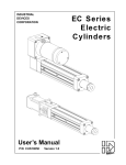
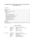
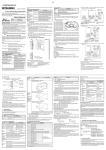
Industrial
Devices
Corporation
The Only Microstepping Drive with:
Open Loop Stall DetectTM (OLSD™)
Multi-SteppingTM
Dynamic SmoothingTM
Xtreme SmoothnessTM
Motion Node
Quick
Setup
& Reference Guide
For more information refer to the Impulse User’s Manual or contact:
Industrial Devices Corporation, 3925 Cypress Dr., Petaluma, CA 94954
(800) 747-0064 - FAX (707) 789-0175 - From outside the U.S. (707) 789-1000
web site: www.idcmotion.com
For more information contact: Industrial Devices Corporation - 3925 Cypress Dr., Petaluma, CA 94954
P/N PCW-5182
Version 1.0
(800) 747-0064 - FAX (707) 789-0175 - Outside the U.S. (707) 789-1000 - web: www.idcmotion.com
P/N PCW-XXXX Revision XX
CAUTION!
•
Do not insert objects into the drive. High voltages could cause personal injury, and equipment could be damaged.
•
Always ensure that power to your system is OFF before connecting a motor or attaching/adjusting a load.
1. Install Application DeveloperTM Software on Windows 95/98/NT/ME/2000
1.
Place the IDC CD in your CD-ROM drive and click on the Start button.
2.
Click on Run.
3.
Type the following in the Command Line box that appears (replace “x” with your CD drive letter): x:\App_Dev\Setupex.exe
4.
Click OK and follow the onscreen instructions.
5.
Restart Windows (recommended).
2. Connect Your PC/Host to Impulse COM PORT (RS232/485)
• Refer to drawings below when making connections.
• Use IDC cable P/N SS-RS232 for making trouble-free RS-232 connections.
COM PORT
IDC P/N
SS-RS232
3 (TX)
2 (RX)
5 (COM)
9-Pin
Connector
RS-232C
COM
PORT
COM PORT
Comm Port Settings
RS-232C/RS-485
Baud Rate
19200 (fixed)
Stop Bits
1
Data Bits
8
Parity
None
XON/XOFF
Yes
TXTX+
RXRX+
COM
RS-485 Host
RS-485
3. Connect Your Motor
• An Interlock jumper must be installed (INTLK to INTLK).
Motor
Connector
IDC Motors
S12/21/23/32/33
P21/22, S21/23
P31/32/33
Quick Disconnect Cable Wire Color
Wiring
A+
Red
ARed/Yellow
*GND
Green
B+
Red/White
BRed/Black
*Gray-colored Quick Disc. cables are
shielded - connect shield to GND.
4. Apply Power
• There is no ON/OFF switch on the Impulse.
• Input voltage must be in the range of 120 VAC ± 10%, single phase, 50/60 Hz, 500 VA max @ 4 Amps.
Operation outside these specifications will result in reduced performance, cause drive faults, or permanently damage the drive.
AC
Power
• Apply AC power by plugging the power cord (included) into the connector on top of the Impulse and into
the power source.
• When power is applied, the LED on front of the drive should turn steady red and remain that way until
the motor is PROBED in Application Developer Project Wizard. If flashing red lights are present see
Diagnostic LED Indications below.
5. Use Application Developer Project Wizard
• Start Application Developer.
• Select Project Wizard.
• Follow the Project Wizard through the
entire setup procedure until you have
clicked on the Finish button.
• You should now see a solid green LED
indicator on the front panel of the
Impulse, and the motor should have
torque.
6. Axis Setup - Advanced Features
• See the Impulse User’s Manual for configuring X-Smoothness, Multi-Stepping, Dynamic Smoothing, Open Loop Stall Detect, and Motion Node.
7. Using an IDC FP100 or FP220 Keypad
• If you are using an IDC Keypad to configure your Impulse, see the Impulse User’s Manual for details and menu descriptions.
8. Reference (see Impulse User’s Manual for details)
Environmental & Mounting Specifications
Operating Ambient Temperature: 0 to 50º C @ 4 Amps
Storage Temperature: -40 to 80º C
Not intended for use in humidity above 95% (non-condensing), or
at altitudes greater than 3,048 meters [10,000 ft.].
Heat Dissipation @ 4 A (typical): 32 W
Leave 6 in. above and below drives for airflow and wiring.
Leave 0.1 in. between drives for easier mounting.
Air supplied to the Impulse must be uncontaminated.
Diagnostic LED Indications
LED Signal
Indication
Green (steady)
Normal Operation
Green - Slow Flash
Shutdown
Green - Quick Flash
Regen Dump
Flashing Green
Drive Disabled
Red (steady)
Motor Not Probed
1 Flash Red
Stalled
2 Flashes Red
Undervoltage Fault
3 Flashes Red
Overvoltage Fault
4 Flashes Red
Overcurrent Fault
5 Flashes Red
Interlock Fault
6 Flashes Red
Overtemperature Fault
7 Flashes Red
EEPROM Checksum Fault
Connecting Digital I/O, Step/Direction/Shutdown Inputs, and Fault Outputs
Application Notes
1.
If using IDC P/N SS-I/O or SS-I/O-6 cable, cut one end of the cable if necessary (see table below for SS-I/O cable
color-code). If you are making your own cable, or are using a non-IDC indexer, refer to the Impulse I/O Schematics and the 25-pin Connector drawing below.
2.
Use a shielded cable, and connect the shield only at the Impulse. Pin 9 is provided for the SHIELD connection.
3.
IDC offers a 25-pin screw-terminal breakout board (P/N DB25BO shown below) to add convenience and flexibility
to your application. Terminals on the breakout board match the pins of the 25-pin connector on the Impulse.
4.
When wiring TTL signals to other manufacturer’s indexers, the Step TTL command signal from the controller
should be wired to Step +, the Direction signal to Dir +, and the Shutdown signal to SD + (Step -, Dir -, and SD should not be connected). Remember, drive and controller COMMONS must be connected.
5.
Activating the Shutdown input disables the drive amplifier and de-energizes the motor. When this input is OFF
the drive is enabled and the motor is energized.
6.
The open collector Fault Output turns ON when any one of the LED-indicated conditions occur (see LED Indications table on next page). The output stays ON while the LED flashes.
7.
Step & Direction Input Voltage: External current-limiting resistor required for 12 and 24 V power supply connections (560 ohm, 1/4 W for 12 V; 1.3 K for 24 V supply).
I/O
PULL-UP +5V, +12V, or 24V
+ANA
RELAY
COIL
Breakout Board
P/N DB25BO
(optional)
SOURCING
INPUT
10K
OUT
OR
MMBT2222ALT1
OUT
2.43K
TO PULLUP COMMON
COM
+5V
COM
Impulse internal
NC
external
FAULT+
FAULT-
FAULT+
FAULT-
FAULT
Output: 0.4 V Max at 100mA Max. sink current; 24V OFF State
FAULT+5V
EQUIVALENT
CIRCUITS
FAULT+
4N35
237
Inputs 3, 4
Impulse internal
external
1K
CMPD914
Single-Ended
IN3/IN4
+5V
LIMIT
SWITCH
(see User's
Manual, Ch. 6
for EOT inputs)
4.02k
4.99K
4.99K
COM
237
STEPDIRSD-
4.99K
STEP+, DIR+, SD+
2.2n 50V
COM
COM
COM
external
Impulse internal
Step & Direction Input Specs.
Input Voltage: HIGH = 3 to 24V Max; LOW = 0 to 1.5V Max.
Voltage
5 to 24 VDC
Current
5 to 15 mA
Setup Time (Dir)
250 ns
Max Freq. (Step)
2 MHz
Inputs 1, 2
+5V
4.99K
Shutdown Input: HIGH = 3.5 to 5V Max; LOW = 0 to 1.5V Max.
OR
IN1/IN2
IN1_BUF
STEPDIRSD-
COM
+5V
DIFFERENTIAL
DRIVER
4.99K
1K
1K
Differential
+5V
4.99 K
4.99 K
AM26LS32
SINKING
OUTPUT
COM
2.2n 50V
COM
AM26LS32
COM
STEP+
DIR+
SD+
COM
TO COMMON
Impulse internal
Impulse internal
external
external
Shutdown (VDC between + and - ): HIGH = 2 to 5V Max; LOW = - 5.0 to - 2.0V Max.
IDC Cable P/N: SS-IO/SS-IO-6
Pin
Impulse Signal
Wire Color
Pin
Impulse Signal
Wire Color
Pin
Impulse Signal
Wire Color
1
STEP +
Brown
10
COM
Gray
19
COM
Black/White
2
STEP -
Red
11
COM
White
20
Reserved
Red/Black
3
DIR +
Orange
12
Reserved
Black
21
Reserved
Orange/Black
4
DIR -
Pink
13
Reserved
Brown/White
22
COM
Yellow/Black
5
SD +
Yellow
14
INPUT 1
Red/White
23
Output 1
Green/Black
6
SD -
Green
15
INPUT 2
Orange/White
24
Reserved
Gray/Black
7
FAULT +
Light Green
16
INPUT 3
Green/White
25
Reserved
Pink/Black
8
FAULT -
Blue
17
INPUT 4
Blue/White
9
Drain
Violet
18
COM
Violet/White
Note: Cable SHIELD is internally connected to
the DB25 metal housing.