1
User Manual
Product Model : DES-3028/DES-3028P/DES-3028G/DES3052/DES-3052P
Managed 10/100Mbps Fast Ethernet Switch
Release 2
©Copyright 2009. All rights reserved.
________________________________________________________________________________________________________
Information in this document is subject to change without notice.
© 2009 D-Link Corporation. All rights reserved.
Reproduction in any manner whatsoever without the written permission of D-Link Computer Corporation is strictly forbidden.
Trademarks used in this text: D-Link and the D-LINK logo are trademarks of D-Link Computer Corporation; Microsoft and Windows are registered trademarks of
Microsoft Corporation.
Other trademarks and trade names may be used in this document to refer to either the entities claiming the marks and names or their products. D-Link Computer
Corporation disclaims any proprietary interest in trademarks and trade names other than its own.
January 2009 P/N 651ES3028025G
©Copyright 2009. All rights reserved.
DES-3028 DES-3028P DES-3028G DES-3052 DES-3052P Layer 2 Fast Ethernet Managed Switch
Table of Contents
Preface........................................................................................................................................................... viii
Intended Readers ............................................................................................................................................ix
Typographical Conventions ...........................................................................................................................ix
Notes, Notices, and Cautions..........................................................................................................................ix
Safety Instructions ...........................................................................................................................................x
Safety Cautions .............................................................................................................................................................................. x
General Precautions for Rack-Mountable Products ...................................................................................................................... xi
Protecting Against Electrostatic Discharge.................................................................................................................................. xii
Introduction......................................................................................................................................................1
DES-3028/28P/28G/52/52P ..............................................................................................................................1
Features.......................................................................................................................................................................................... 1
Ports ............................................................................................................................................................................................... 2
LED Indicators............................................................................................................................................................................... 3
Front-Panel Description ................................................................................................................................................................. 5
Rear Panel Description................................................................................................................................................................... 6
Side Panel Description ................................................................................................................................................................... 6
Gigabit Combo Ports...................................................................................................................................................................... 7
Installing the SFP ports .................................................................................................................................................................. 8
Installation ........................................................................................................................................................9
Package Contents ........................................................................................................................................................................... 9
Before You Connect to the Network.............................................................................................................................................. 9
Installing the Switch without the Rack ........................................................................................................................................ 10
Installing the Switch in a Rack..................................................................................................................................................... 10
Mounting the Switch in a Standard 19" Rack .............................................................................................................................. 11
Connecting the Switch ...................................................................................................................................12
Switch to End Node ..................................................................................................................................................................... 12
Switch to Hub or Switch .............................................................................................................................................................. 13
Introduction to Switch Management ...........................................................................................................14
Management Options.....................................................................................................................................14
Web-based Management Interface............................................................................................................................................... 14
SNMP-Based Management.......................................................................................................................................................... 14
Connecting the Console Port (RS-232 DCE)............................................................................................................................... 14
First Time Connecting to the Switch ........................................................................................................................................... 16
Password Protection..................................................................................................................................................................... 16
SNMP Settings............................................................................................................................................................................. 17
IP Address Assignment................................................................................................................................................................ 18
Web-based Switch Configuration.................................................................................................................21
Introduction....................................................................................................................................................21
ii
DES-3028 DES-3028P DES-3028G DES-3052 DES-3052P Layer 2 Fast Ethernet Managed Switch
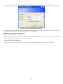
Login to Web Manager ................................................................................................................................................................ 21
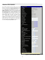
Web-based User Interface ............................................................................................................................................................ 22
Web Pages.................................................................................................................................................................................... 24
Administration ...............................................................................................................................................25
Device Information ........................................................................................................................................26
IP Address.......................................................................................................................................................28
Setting the Swith’s IP Address using the Console Interface ........................................................................................................ 30
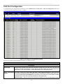
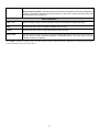
Port Configuration.........................................................................................................................................31
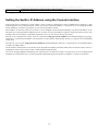
Port Settings ................................................................................................................................................................................. 31
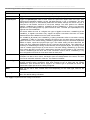
Port Description ........................................................................................................................................................................... 33
Port Error Disabled ...................................................................................................................................................................... 33
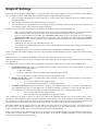
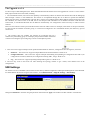
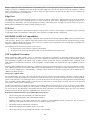
DHCP/BOOTP Relay ....................................................................................................................................35
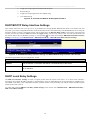
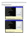
DHCP/BOOTP Relay Global Settings......................................................................................................................................... 35
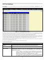
DHCP/BOOTP Relay Interface Settings...................................................................................................................................... 38
DHCP Local Relay Settings......................................................................................................................................................... 38
User Accounts.................................................................................................................................................40
Cable Diagnostics ...........................................................................................................................................42
Port Mirroring ...............................................................................................................................................44
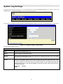
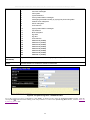
System Log Settings .......................................................................................................................................45
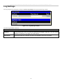
Log Settings ....................................................................................................................................................47
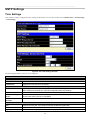
SNTP Settings.................................................................................................................................................48
Time Settings ............................................................................................................................................................................... 48
Time Zone and DST..................................................................................................................................................................... 49
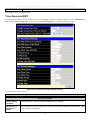
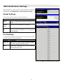
MAC Notification Settings ............................................................................................................................51
TFTP Services ................................................................................................................................................52
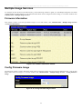
Multiple Image Services ................................................................................................................................53
Firmware Information .................................................................................................................................................................. 53
Config Firmware Image ............................................................................................................................................................... 53
Ping Test .........................................................................................................................................................54
Safeguard Engine ...........................................................................................................................................54
SNMP Manager..............................................................................................................................................57
SNMP Settings............................................................................................................................................................................. 57
SNMP Traps Settings................................................................................................................................................................... 58
SNMP User Table ........................................................................................................................................................................ 58
SNMP View Table ....................................................................................................................................................................... 60
SNMP Group Table ..................................................................................................................................................................... 61
SNMP Community Table Configuration ..................................................................................................................................... 62
SNMP Host Table ........................................................................................................................................................................ 63
SNMP Engine ID ......................................................................................................................................................................... 64
PoE System .....................................................................................................................................................65
iii
DES-3028 DES-3028P DES-3028G DES-3052 DES-3052P Layer 2 Fast Ethernet Managed Switch
PoE System Configuration........................................................................................................................................................... 65
PoE Port Configuration................................................................................................................................................................ 66
Single IP Settings............................................................................................................................................68
SIM Settings................................................................................................................................................................................. 69
Topology...................................................................................................................................................................................... 71
Tool Tips...................................................................................................................................................................................... 73
Right-Click................................................................................................................................................................................... 74
Menu Bar ..................................................................................................................................................................................... 76
Firmware Upgrade ....................................................................................................................................................................... 77
Configuration Backup/Restore..................................................................................................................................................... 77
Upload Log .................................................................................................................................................................................. 78
Forwarding & Filtering.................................................................................................................................78
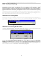
Unicast Forwarding...................................................................................................................................................................... 78
Multicast Forwarding................................................................................................................................................................... 79
Multicast Filtering Mode ............................................................................................................................................................. 81
SMTP Service .................................................................................................................................................82
SMTP Server Settings.................................................................................................................................................................. 83
SMTP Service .............................................................................................................................................................................. 83
L2 Features .....................................................................................................................................................85
VLANs.............................................................................................................................................................85
Static VLAN Entry....................................................................................................................................................................... 90
GVRP Settings ............................................................................................................................................................................. 92
VLAN Trunk Settings.................................................................................................................................................................. 94
QinQ............................................................................................................................................................................................. 96
Trunking .........................................................................................................................................................98
Link Aggregation ......................................................................................................................................................................... 99
LACP Port Settings...................................................................................................................................................................... 99
IGMP Snooping............................................................................................................................................101
Router Ports Settings.................................................................................................................................................................. 103
IGMP Authentication................................................................................................................................................................. 105
Dynamic IP Multicast Learning ................................................................................................................................................. 107
ISM VLAN Settings................................................................................................................................................................... 108
IP Multicast Filter Profile Settings............................................................................................................................................. 110
Limited Multicast Range Settings.............................................................................................................................................. 111
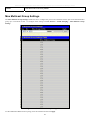
Max Multicast Group Settings ................................................................................................................................................... 113
MLD Snooping .............................................................................................................................................114
MLD Snooping Settings............................................................................................................................................................. 114
MLD Snooping Router Port Settings ......................................................................................................................................... 116
Spanning Tree ..............................................................................................................................................117
STP Bridge Global Settings ....................................................................................................................................................... 120
STP Port Settings ....................................................................................................................................................................... 123
iv
DES-3028 DES-3028P DES-3028G DES-3052 DES-3052P Layer 2 Fast Ethernet Managed Switch
MST Configuration Identification.............................................................................................................................................. 125
STP Instance Settings................................................................................................................................................................. 127
MSTP Port Information ............................................................................................................................................................. 128
Loopback Detection Settings.......................................................................................................................130
LLDP.............................................................................................................................................................131
LLDP Global Settings................................................................................................................................................................ 131
Basic LLDP Port Settings .......................................................................................................................................................... 133
802.1 Extension LLDP Port Settings ......................................................................................................................................... 134
802.3 Extension LLDP Port Settings ......................................................................................................................................... 136
LLDP Management Address Settings ........................................................................................................................................ 138
LLDP Statistics .......................................................................................................................................................................... 139
LLDP Management Address Table............................................................................................................................................ 140
LLDP Local Port Table.............................................................................................................................................................. 140
LLDP Remote Port Table .......................................................................................................................................................... 142
CoS ................................................................................................................................................................143
Port Bandwidth ............................................................................................................................................146
802.1p Default Priority ................................................................................................................................147
802.1p User Priority.....................................................................................................................................149
CoS Scheduling Mechanism........................................................................................................................149
CoS Output Scheduling ...............................................................................................................................150
Priority Settings ...........................................................................................................................................151
TOS Priority Settings ..................................................................................................................................153
DSCP Priority Settings ................................................................................................................................154
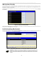
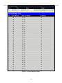
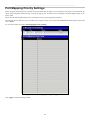
Port Mapping Priority Settings ..................................................................................................................155
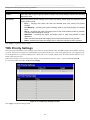
MAC Priority ...............................................................................................................................................156
ACL ...............................................................................................................................................................157
Time Range...................................................................................................................................................157
Access Profile Table.....................................................................................................................................157
CPU Interface Filtering...............................................................................................................................169
CPU Interface Filtering State ..................................................................................................................................................... 169
CPU Interface Filtering Profile Table ........................................................................................................................................ 169
Security .........................................................................................................................................................181
Traffic Control .............................................................................................................................................181
Port Security.................................................................................................................................................185
Port Lock Entries.........................................................................................................................................186
IP-MAC-Port Binding .................................................................................................................................187
IMP Global Settings................................................................................................................................................................... 187
IMP Port Settings....................................................................................................................................................................... 187
IMP Entry Settings..................................................................................................................................................................... 189
v
DES-3028 DES-3028P DES-3028G DES-3052 DES-3052P Layer 2 Fast Ethernet Managed Switch
DHCP Snooping Entries ............................................................................................................................................................ 190
MAC Block List......................................................................................................................................................................... 190
SSL ................................................................................................................................................................191
Download Certificate ................................................................................................................................................................. 191
Ciphersuite ................................................................................................................................................................................. 191
SSH ................................................................................................................................................................194
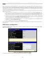
SSH Server Configuration ......................................................................................................................................................... 194
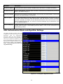
SSH Authentication Mode and Algorithm Settings ................................................................................................................... 195
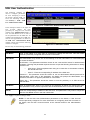
SSH User Authentication ........................................................................................................................................................... 197
802.1X............................................................................................................................................................198
802.1X Authenticator Settings ................................................................................................................................................... 205
Local Users ................................................................................................................................................................................ 208
802.1X Capability Settings ........................................................................................................................................................ 209
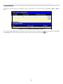
Configure 802.1X Guest VLAN ................................................................................................................................................ 209
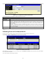
Initializing Ports for Port Based 802.1X .................................................................................................................................... 210
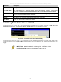
Initializing Ports for Host Based 802.1X ................................................................................................................................... 211
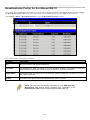
Reauthenticate Port(s) for Port Based 802.1X ........................................................................................................................... 212
Reauthenticate Port(s) for Host-based 802.1X........................................................................................................................... 213
RADIUS Server ......................................................................................................................................................................... 213
Trusted Host .................................................................................................................................................214
Access Authentication Control ...................................................................................................................215
Authentication Policy and Parameter Settings ........................................................................................................................... 216
Application Authentication Settings .......................................................................................................................................... 216
Authentication Server Group ..................................................................................................................................................... 217
Authentication Server Host ........................................................................................................................................................ 218
Login Method Lists.................................................................................................................................................................... 221
Enable Method Lists .................................................................................................................................................................. 222
Configure Local Enable Password ............................................................................................................................................. 225
Enable Admin ............................................................................................................................................................................ 225
Traffic Segmentation ...................................................................................................................................226
DoS Attack Prevention ................................................................................................................................227
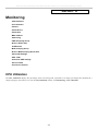
Monitoring ....................................................................................................................................................232
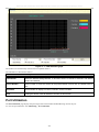
CPU Utilization ............................................................................................................................................232
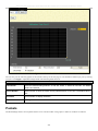
Port Utilization .............................................................................................................................................233
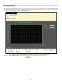
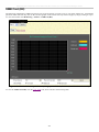
Packets ..........................................................................................................................................................234
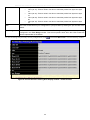
Received (RX) ........................................................................................................................................................................... 235
UMB Cast (RX) ......................................................................................................................................................................... 237
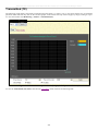
Transmitted (TX) ....................................................................................................................................................................... 239
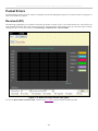
Packet Errors ...............................................................................................................................................241
Received (RX) ........................................................................................................................................................................... 241
vi
DES-3028 DES-3028P DES-3028G DES-3052 DES-3052P Layer 2 Fast Ethernet Managed Switch
Transmitted (TX) ....................................................................................................................................................................... 243
Packet Size ....................................................................................................................................................245
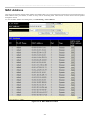
MAC Address ...............................................................................................................................................247
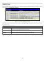
Switch Log ....................................................................................................................................................249
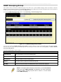
IGMP Snooping Group ...............................................................................................................................250
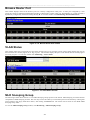
Browse Router Port .....................................................................................................................................251
VLAN Status.................................................................................................................................................251
MLD Snooping Group.................................................................................................................................251
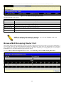
Browse MLD Snooping Router Port ..........................................................................................................252
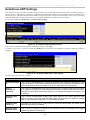
Static ARP Settings ......................................................................................................................................253
ARP-FDB ......................................................................................................................................................253
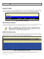
Gratuitous ARP Settings .............................................................................................................................255
Session Table ................................................................................................................................................256
Port Access Control .....................................................................................................................................256
RADIUS Authentication ............................................................................................................................................................ 256
RADIUS Accounting ................................................................................................................................................................. 258
Reset ..............................................................................................................................................................259
Reboot System ..............................................................................................................................................260
Save Changes................................................................................................................................................260
Logout ...........................................................................................................................................................261
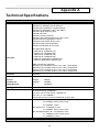
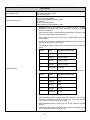
Technical Specifications ..............................................................................................................................262
System Log Entries ......................................................................................................................................268
Standard Trap List...................................................................................................................................................................... 278
Proprietary Trap List.................................................................................................................................................................. 279
Proprietary Trap List (project dependent).................................................................................................................................. 279
Cable Lengths...............................................................................................................................................281
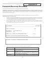
Password Recovery Procedure ...................................................................................................................282
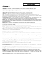
Glossary ........................................................................................................................................................284
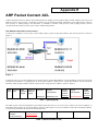
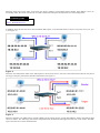
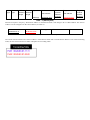
ARP Packet Content ACL...........................................................................................................................286
Warranties/Registration..............................................................................................................................296
Tech Support ................................................................................................................................................305
vii
DES-3028 DES-3028P DES-3028G DES-3052 DES-3052P Layer 2 Fast Ethernet Managed Switch
Preface
The DES-3028/DES-3028P/DES-3028G/DES-3052/DES-3052P User Manual is divided into sections that describe the system
installation and operating instructions with examples.
Section 1, Introduction - Describes the Switch and its features.
Section 2, Installation - Helps you get started with the basic installation of the Switch and also describes the front panel, rear
panel, side panels, and LED indicators of the Switch.
Section 3, Connecting the Switch - Tells how you can connect the Switch to your Ethernet/Fast Ethernet network.
Section 4, Introduction to Switch Management - Introduces basic Switch management features, including password protection,
SNMP settings, IP address assignment and connecting devices to the Switch.
Section 5, Introduction to Web-based Switch Management - Talks about connecting to and using the Web-based switch
management feature on the Switch.
Section 6, Administration - A detailed discussion about configuring the basic functions of the Switch, including Device
Information, IP Address, Port Configuration, DHCP/BOOTP Relay, User Accounts, Cable Diagnostics, Port Mirroring, System
Log Settings, Log Settings, SNTP Settings, MAC Notification Settings, TFTP Services, Multiple Image Services, Ping Test,
Safeguard Engine, SNMP Manager, Single IP Settings, Forwarding & Filtering, and SMTP Service.
Section 7, Layer 2 Features - A discussion of Layer 2 features of the Switch, including VLAN, QinQ, Trunking, IGMP
Snooping, MLD Snooping, Spanning Tree, Loopback Detection and LLDP.
Section 8, CoS - Features information on CoS, including Port Bandwidth, 802.1P Default Priority, 802.1P User Priority, CoS
Scheduling Mechanism, CoS Output Scheduling, Priority Settings, TOS Priority Settings, DSCP Priority Settings, Port Mapping
Priority Settings, and MAC Priority.
Section 9, ACL - Discussion on the ACL function of the Switch, including Time Range, Access Profile Table and CPU Interface
Filtering.
Section 10, Security - A discussion on the Security functions on the Switch, including Traffic Control, Port Security, Port Lock
Entries, IP-MAC-Port Binging, SSL, SSH, 802.1X, Trusted Host, Access Authentication Control, Traffic Segmentation and DoS
Attack Prevention.
Section 11, Monitoring - Features information on Monitoring including CPU Utilization, Port Utilization, Packets, Packet Errors,
Packet Size, MAC Address, Switch Log, IGMP Snooping Group, Browse Router Port, VLAN Status, MLD Snooping Group,
Browse MLD Snooping Router Port, Static ARP Settings, ARP-FDB, Gratuitous ARP Settings, Session Table, and Port Access
Control.
Appendix A, Technical Specifications - Technical specifications for the DES-3028/DES-3028P/DES-3028G/DES-3052 and the
DES-3052P.
Appendix B, System Log Entries - Information on the System Log Entries
Appendix C, Cable Lengths - Information on cable types and maximum distances.
Appendix D, Glossary - Lists definitions for terms and acronyms used in this document.
viii
DES-3028 DES-3028P DES-3028G DES-3052 DES-3052P Layer 2 Fast Ethernet Managed Switch
Intended Readers
The DES-3028/DES-3028P/DES-3028G/DES-3052/DES-3052P User Manual contains information for setup and management of
the Switch. The term, “the Switch” will be used when referring to all five switches. This manual is intended for network managers
familiar with network management concepts and terminology.
Typographical Conventions
Convention
Description
[]
In a command line, square brackets indicate an optional entry. For example: [copy filename]
means that optionally you can type copy followed by the name of the file. Do not type the
brackets.
Bold font
Indicates a button, a toolbar icon, menu, or menu item. For example: Open the File menu
and choose Cancel. Used for emphasis. May also indicate system messages or prompts
appearing on your screen. For example: You have mail. Bold font is also used to represent
filenames, program names and commands. For example: use the copy command.
Boldface
Typewriter Font
Indicates commands and responses to prompts that must be typed exactly as printed in the
manual.
Initial capital letter
Indicates a window name. Names of keys on the keyboard have initial capitals. For example:
Click Enter.
Italics
Indicates a window name or a field. Also can indicate a variables or parameter that is
replaced with an appropriate word or string. For example: type filename means that you
should type the actual filename instead of the word shown in italic.
Menu Name > Menu
Option
Menu Name > Menu Option Indicates the menu structure. Device > Port > Port
Properties means the Port Properties menu option under the Port menu option that is
located under the Device menu.
Notes, Notices, and Cautions
A NOTE indicates important information that helps you make better use of your device.
A NOTICE indicates either potential damage to hardware or loss of data and tells you
how to avoid the problem.
A CAUTION indicates a potential for property damage, personal injury, or death.
ix
DES-3028 DES-3028P DES-3028G DES-3052 DES-3052P Layer 2 Fast Ethernet Managed Switch
Safety Instructions
Use the following safety guidelines to ensure your own personal safety and to help protect your system from potential damage.
Throughout this document, the caution icon (
) is used to indicate cautions and precautions that you need to review and
follow.
Safety Cautions
To reduce the risk of bodily injury, electrical shock, fire, or damage to the equipment, observe the following precautions.
Observe and follow service markings.
Do not service any product except as explained in your system documentation.
Opening or removing covers that are marked with the triangular symbol with a lightning bolt may expose you to
electrical shock.
Only a trained service technician should service components inside these compartments.
If any of the following conditions occur, unplug the product from the electrical outlet and replace the part or contact your
trained service provider:
The power cable, extension cable, or plug is damaged.
An object has fallen into the product.
The product has been exposed to water.
The product has been dropped or damaged.
The product does not operate correctly when you follow the operating instructions.
Keep your system away from radiators and heat sources. Also, do not block cooling vents.
Do not spill food or liquids on your system components, and never operate the product in a wet environment. If the system
gets wet, see the appropriate section in your troubleshooting guide or contact your trained service provider.
Do not push any objects into the openings of your system. Doing so can cause fire or electric shock by shorting out interior
components.
Use the product only with approved equipment.
Allow the product to cool before removing covers or touching internal components.
Operate the product only from the type of external power source indicated on the electrical ratings label. If you are not sure
of the type of power source required, consult your service provider or local power company.
To help avoid damaging your system, be sure the voltage on the power supply is set to match the power available at your
location:
115 volts (V)/60 hertz (Hz) in most of North and South America and some Far Eastern countries such as South
Korea and Taiwan
100 V/50 Hz in eastern Japan and 100 V/60 Hz in western Japan
230 V/50 Hz in most of Europe, the Middle East, and the Far East
Also, be sure that attached devices are electrically rated to operate with the power available in your location.
Use only approved power cable(s). If you have not been provided with a power cable for your system or for any ACpowered option intended for your system, purchase a power cable that is approved for use in your country. The power cable
must be rated for the product and for the voltage and current marked on the product's electrical ratings label. The voltage and
current rating of the cable should be greater than the ratings marked on the product.
To help prevent electric shock, plug the system and peripheral power cables into properly grounded electrical outlets. These
cables are equipped with three-prong plugs to help ensure proper grounding. Do not use adapter plugs or remove the
grounding prong from a cable. If you must use an extension cable, use a 3-wire cable with properly grounded plugs.
Observe extension cable and power strip ratings. Make sure that the total ampere rating of all products plugged into the
extension cable or power strip does not exceed 80 percent of the ampere ratings limit for the extension cable or power strip.
x
DES-3028 DES-3028P DES-3028G DES-3052 DES-3052P Layer 2 Fast Ethernet Managed Switch
To help protect your system from sudden, transient increases and decreases in electrical power, use a surge suppressor, line
conditioner, or uninterruptible power supply (UPS).
Position system cables and power cables carefully; route cables so that they cannot be stepped on or tripped over. Be sure
that nothing rests on any cables.
Do not modify power cables or plugs. Consult a licensed electrician or your power company for site modifications. Always
follow your local/national wiring rules.
When connecting or disconnecting power to hot-pluggable power supplies, if offered with your system, observe the
following guidelines:
Install the power supply before connecting the power cable to the power supply.
Unplug the power cable before removing the power supply.
If the system has multiple sources of power, disconnect power from the system by unplugging all power cables from
the power supplies.
Move products with care; ensure that all casters and/or stabilizers are firmly connected to the system. Avoid sudden stops
and uneven surfaces.
General Precautions for Rack-Mountable Products
Observe the following precautions for rack stability and safety. Also, refer to the rack installation documentation accompanying
the system and the rack for specific caution statements and procedures.
Systems are considered to be components in a rack. Thus, "component" refers to any system as well as to various peripherals
or supporting hardware.
Before working on the rack, make sure that the stabilizers are secured to the rack, extended to the floor, and that the full
weight of the rack rests on the floor. Install front and side stabilizers on a single rack or front stabilizers for joined multiple
racks before working on the rack.
Always load the rack from the bottom up, and load the heaviest item in the rack first.
Make sure that the rack is level and stable before extending a component from the rack.
Use caution when pressing the component rail release latches and sliding a component into or out of a rack; the slide rails
can pinch your fingers.
After a component is inserted into the rack, carefully extend the rail into a locking position, and then slide the component
into the rack.
Do not overload the AC supply branch circuit that provides power to the rack. The total rack load should not exceed 80
percent of the branch circuit rating.
Ensure that proper airflow is provided to components in the rack.
Do not step on or stand on any component when servicing other components in a rack.
NOTE: A qualified electrician must perform all connections to DC power and to safety
grounds. All electrical wiring must comply with applicable local, regional or national codes
and practices.
CAUTION: Never defeat the ground conductor or operate the equipment in the absence of a
suitably installed ground conductor. Contact the appropriate electrical inspection authority or
an electrician if you are uncertain that suitable grounding is available.
xi
DES-3028 DES-3028P DES-3028G DES-3052 DES-3052P Layer 2 Fast Ethernet Managed Switch
CAUTION: The system chassis must be positively grounded to the rack cabinet frame. Do
not attempt to connect power to the system until grounding cables are connected. A
qualified electrical inspector must inspect completed power and safety ground wiring. An
energy hazard will exist if the safety ground cable is omitted or disconnected.
CAUTION: Do not replace the battery with an incorrect type. The risk of explosion exists if
the replacement battery is not the correct lithium battery type. Dispose of used batteries
according to the instructions.
Protecting Against Electrostatic Discharge
Static electricity can harm delicate components inside your system. To prevent static damage, discharge static electricity from
your body before you touch any of the electronic components, such as the microprocessor. You can do so by periodically touching
an unpainted metal surface on the chassis.
You can also take the following steps to prevent damage from electrostatic discharge (ESD):
1.
When unpacking a static-sensitive component from its shipping carton, do not remove the component from the antistatic
packing material until you are ready to install the component in your system. Just before unwrapping the antistatic
packaging, be sure to discharge static electricity from your body.
2.
When transporting a sensitive component, first place it in an antistatic container or packaging.
3.
Handle all sensitive components in a static-safe area. If possible, use antistatic floor pads, workbench pads and an
antistatic grounding strap.
xii
DES-3028 DES-3028P DES-3052 DES-3052P Layer 2 Fast Ethernet Managed Switch
Section 1
Introduction
DES-3028/28P/28G/52/52P Switch Description
Features
Ports
LED Indicators
Front-Panel Description
Rear Panel Description
Side Panel Description
Installing SFP ports
DES-3028/28P/28G/52/52P
The DES-3028, DES-3028P, DES-3028G, DES-3052, and the DES-3052P are all members of the D-Link Switch family. These
Switches provide unsurpassed performance, fault tolerance, scalable flexibility, robust security, standard-based interoperability
and impressive technology to future-proof departmental and enterprise network deployments with an easy migration path.
The following manual describes the installation, maintenance, and configurations concerning the DES-3028, DES-3028P, DES3028G, DES-3052, and DES-3052P. These five Switches are identical in configuration and very similar in basic hardware and
consequentially, most of the information in this manual will be universal to the total group of switches. Corresponding screen
pictures of the web manager may be taken from any one of these switches but the configuration will be identical, except for
varying port counts. For the remainder of this document, we will use the DES-3028G as the Switch in question for examples,
screen shots, configurations, and explanations.
Features
IEEE 802.3ad Link Aggregation Control Protocol support
IEEE 802.1X Port-based and Host-based Access Control
IEEE 802.1Q VLAN
IEEE 802.1D Spanning Tree, IEEE 802.1w Rapid Spanning Tree and IEEE 802.1s Multiple Spanning Tree support
Access Control List (ACL) support
Single IP Management support
Access Authentication Control utilizing TACACS, XTACACS and TACACS+
Internal Flash Drive for saving configurations and firmware
Simple Network Time Protocol support
MAC Notification support
System and Port Utilization support
System Log Support
Support port-based enable and disable
Address table: Supports up to 8K MAC addresses per device
Supports a packet buffer of up to 512K bytes
Supports Port-based VLAN Groups
Port Trunking with flexible load distribution and fail-over function
IGMP Snooping support
SNMP support
Secure Sockets Layer (SSL) and Secure Shell (SSH) support
Port Mirroring support
MIB support for:
RFC1213 MIB II
1
DES-3028 DES-3028P DES-3052 DES-3052P Layer 2 Fast Ethernet Managed Switch
RFC1493 Bridge
RFC2819 RMON
RFC2665 Ether-like MIB
RFC2863 Interface MIB
Private MIB
RFC2674 for 802.1p
IEEE 802.1X MIB
IEEE 802.3x flow control in full duplex mode
IEEE 802.1p Priority Queues
IEEE 802.3u 100BASE-TX compliant
RS-232 DCE console port for Switch management
Provides parallel LED display for port status such as link/act, speed, etc.
IEEE 802.3 10BASE-T compliant
High performance switching engine performs forwarding and filtering at wire speed, maximum 14,881 packets/sec
on each 10Mbps Ethernet port, maximum 148,810 packet/sec on 100Mbps Fast Ethernet port and 1,488,100 for each
Gigabit port
Full and half-duplex for both 10Mbps and 100Mbps connections. Full duplex allows the switch port to
simultaneously transmit and receive data. It only works with connections to full-duplex-capable end stations and
switches. Connections to a hub must take place at half-duplex
Support Broadcast/Multicast storm control
Non-blocking store and forward switching scheme capability to support rate adaptation and protocol conversion
Supports by-port Egress/Ingress rate control
Efficient self-learning and address recognition mechanism enables forwarding rate at wire speed
2
DES-3028 DES-3028P DES-3028G DES-3052 DES-3052P Layer 2 Fast Ethernet Managed Switch
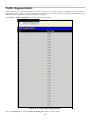
Ports
The following table lists the relative ports that are present within each switch:
DES-3028 and DES-3028P
DES-3028G
DES-3052 and DES-3052P
Twenty-four 10/100BASE-T
Twenty-four 10/100BASE-T
Forty-eight 10/100Mbps Ports
Two 1000Base-T/SFP Combo
Ports
Four 1000Base-T/SFP Combo
Ports
Two 1000Base-T/SFP Combo Ports
Two 1000Base-T Ports
One female DCE RS-232 DB-9
console port
One female DCE RS-232 DB-9
console port
Two 1000Base-T Ports
One female DCE RS-232 DB-9
console port
The following table lists the features and compatibility for each type of port present in the DES-3028/28P/28G/52/52P.
10/100/1000BASE-T
IEEE 802.3 compliant
IEEE 802.3u compliant
IEEE 802.3x flow control
support in full-duplex
Auto MDI-X/MDI-II cross
over supported except
for speed 1000M force
mode.
SFP Combo
SFP Transceivers Supported:
DEM-310GT (1000BASE-LX)
DEM-311GT (1000BASE-SX)
DEM-314GT (1000BASE-LH)
DEM-315GT (1000BASE-ZX)
DEM-210
(Single
Mode
100BASE-FX)
DEM-211
(Multi
Mode
100BASE-FX)
1000BASE-T Combo
IEEE 802.3 compliant
IEEE 802.3u compliant
IEEE 802.3ab compliant
IEEE 802.3z compliant
IEEE 802.3x flow control
support in full-duplex
WDM Transceiver Supported:
DEM-330T
(TX-1550/RX1310nm), up to 10km,SingleMode
DEM-330R
(TX-1310/RX1550nm), up to 10km,SingleMode
DEM-331T
(TX-1550/RX1310nm), up to 40km, SingleMode
DEM-331R
(TX-1310/RX1550nm), up to 40km, SingleMode
Compliant to the following
standards:
1. IEEE 802.3z compliance
2.IEEE 802.3u compliance
NOTE: The SFP combo ports on the Switch cannot be used simultaneously with the
corresponding 1000BASE-T ports. If both ports are in use at the same time (ex. port 25
of the SFP and port 25 of the 1000BASE-T), the SFP ports will take priority over the
combo ports and render the 1000BASE-T ports inoperable.
2
DES-3028 DES-3028P DES-3028G DES-3052 DES-3052P Layer 2 Fast Ethernet Managed Switch
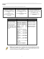
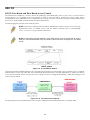
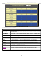
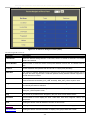
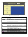
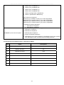
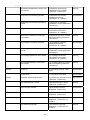
LED Indicators
The Switch supports LED indicators for Power, Console, RPS and Port LEDs. The following shows the LED indicators for the
DES-3028/28P/28G/52/52P Series switches along with an explanation of each indicator. LEDs and there corresponding meanings
are displayed below.
Figure 1- 1. LED Indicators on DES-3028 Switch
Figure 1- 2. LED Indicators on DES-3028P Switch
Figure 1- 3. LED Indicators on DES-3028G Switch
Figure 1- 4. LED Indicators on DES-3052/DES-3052P Switch
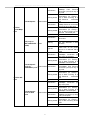
Location
LED Indicative
Color
Status
Description
Power
Green
Solid Light
Power On
Light off
Power Off
Solid Light
Console on
Blinking
POST is in progress/ POST
is failure.
Light off
Console off
Green
Solid Light
Link/Act/Speed Mode
Green
Solid Light
PoE Mode
Per Device
Console
“Mode Select Link/Act/ Speed
Button”(only
for DES3028P/DES- PoE
3052P)
Green
3
DES-3028 DES-3028P DES-3028G DES-3052 DES-3052P Layer 2 Fast Ethernet Managed Switch
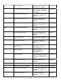
Link/Act/Speed
LED Per
10/100 Mbps
Port
PoE (only for
DES-3028P/DES3052P)
When there is a secure
100Mbps
Fast
Ethernet
Solid Green
connection (or link) at any of
the ports.
When there is reception or
transmission (i.e. Activity—
Blinking Green Act) of data occurring at a
Fast Ethernet
connected
port.
Green/Amber
When there is a secure
Solid Amber
10Mbps Ethernet connection
(or link) at any of the ports.
When there is reception or
transmission (i.e. Activity—
Blinking Amber
Act) of data occurring at an
Ethernet connected port.
Light off
No link
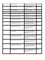
Green
Solid Green
Powered
connected.
Blinking
Port has detected a error
condition
Light off
Solid Green
Blinking Green
Link/Act/Speed
Green/Amber
mode for
Solid Amber
1000BASE-T ports
Blinking Amber
LED Per GE
Port
Light off
Solid Green
Blinking Green
Link/Act/Speed
mode for SFP
ports
Green/Amber
Solid Amber
Blinking Amber
Light off
4
device
is
Powered Device may receive
power from an AC power
source or no 802.3af PD is
found
When there is a secure
1000Mbps connection (or
link) at any of the ports.
When there is reception or
transmission (i.e. Activity-Act) of data occurring at a
1000Mbps connected port.
When there is a secure
10/100Mbps Fast Ethernet
connection (or link) at any of
the ports.
When there is reception or
transmission (i.e. Activity—
Act) of data occurring at a
Fast Ethernet
connected
port.
No link
When there is a secure
1000Mbps connection (or
link) at the ports.
When there is reception or
transmission (i.e. Activity-Act) of data occurring at a
1000Mbps connected port.
When there is a secure
100Mbps connection (or link)
at any of the ports.
When there is reception or
transmission (i.e. Activity—
Act) of data occurring at the
ports.
No link
DES-3028 DES-3028P DES-3028G DES-3052 DES-3052P Layer 2 Fast Ethernet Managed Switch
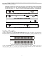
Front-Panel Description
DES-3028/DES-3028P
Twenty-four 10/100Mbps BASE-T ports
Two Combo 1000BASE-T/SFP ports located to the right
Two 1000BASE-T ports located to the right
One female DCE RS-232 DB-9 console port
LEDs for Power, Console, PoE, Link/Act/Speed for each port
Figure 1- 5. Front Panel of the DES-3028/DES-3028P
DES-3052P/DES-3052
Forty-eight 10/100Mbps BASE-T ports
Two Combo 1000BASE-T/SFP ports located to the right
Two 1000BASE-T ports located to the right
One female DCE RS -232 DB-9 console port
LEDs for Power, Console, PoE, Link/Act/Speed for each port
Figure 1- 6. Front Panel of the DES-3052P/DES-3052
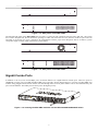
DES-3028G
Twenty-four 10/100Mbps BASE-T ports
Four Combo 1000BASE-T/SFP ports located to the right
One female DCE RS -232 DB-9 console port
LEDs for Power, Console, Link/Act/Speed for each port
1
5
9
10M
100M
13 17
21
25
2
6
10
14
18
22
26
Power
3
7
11
15
19
23
27
Console
4
8
12
16
20
24
28
FE Port
Managed Switch
DES-3028G
GE Port
10/100M
1000M
Link
1
3
5
7
9
11
13
15
17
19
21
23
Combo1
25
27
Combo3
2
4
6
8
10
12
14
16
18
20
22
24
Combo2
26
28
Combo4
Act
Console
Figure 1- 7. Front Panel of the DES-3028G
分頁符號
5
DES-3028 DES-3028P DES-3028G DES-3052 DES-3052P Layer 2 Fast Ethernet Managed Switch
Rear Panel Description
The rear panel of the Switch contains an AC power connector. The AC power connector is a standard three-pronged
connector that supports the power cord. Plug-in the female connector of the provided power cord into this socket, and the
male side of the cord into a power outlet. The Switch automatically adjusts its power setting to any supply voltage in the
range from 100 ~ 240 VAC at 50 ~ 60 Hz. The rear panel of the DES-3052/DES-3052P contains one female DCE RS 232 DB-9 console port.
Figure 1- 8. Rear panel view of the DES-3028P
Console
AC LINE
100-240 VAC
50-60 Hz
5A MAX
Figure 1- 9. Rear panel view of the DES-3052P
Figure 1- 10. Rear panel view of the DES-3028G/DES-3028
Console
AC LINE
100-240 VAC
50-60 Hz
0.5A MAX
Figure 1- 11. Rear panel view of the DES-3052
Side Panel Description
The left and right-hand panel of the DES-3028G/DES-3028/DES-3052 Switches contain heat vents. The heat vents are used to
dissipate heat. Do not block these openings, and leave at least 6 inches of space at the rear and sides of the Switch for proper
ventilation. Be reminded that without proper heat dissipation and air circulation, system components might overheat, which could
lead to system failure.
Figure 1- 12. Side panels of the DES-3028G/DES-3028/DES-3052
The sides of the DES-3028P have heat vents to serve to dissipate heat. Do not block these openings, and leave at least 6 inches of
space at the rear and sides of the Switch for proper ventilation. Be reminded that without proper heat dissipation and air
circulation, system components might overheat, which could lead to system failure.
6
DES-3028 DES-3028P DES-3028G DES-3052 DES-3052P Layer 2 Fast Ethernet Managed Switch
Figure 1- 13. Side panels of the DES-3028P
The left-hand side panel of the DES-3052P Switch contains a system fan and ventilation along the entire right side. The system
fan is used to dissipate heat. Do not block these openings on either side of the Switch. Leave at least 6 inches of space at the rear
and sides of the Switch for proper ventilation. Be reminded that without proper heat dissipation and air circulation, system
components might overheat, which could lead to system failure.
Figure 1- 14. Side panels of the DES-3052P
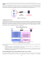
Gigabit Combo Ports
In addition to the 24 (or 48) 10/100 Mbps ports, the Switch features two Gigabit Ethernet Combo ports. These two ports are
1000BASE-T copper ports (provided) and Mini-GBIC ports (optional). See the diagram below to view the two Mini-GBIC port
modules being plugged into the Switch. Please note that although these two front panel modules can be used simultaneously, the
ports must be different. The GBIC port will always have the highest priority.
Figure 1- 15. Inserting the Mini-GBIC modules into the DES-3028/28P/28G/52/52P Switch
7
DES-3028 DES-3028P DES-3028G DES-3052 DES-3052P Layer 2 Fast Ethernet Managed Switch
Figure 1- 16. Installing the Mini-GBIC Module
Installing the SFP ports
The DES-3028/28P/28G/52/52P Switches are equipped with SFP (Small Form Factor Portable) ports, which are to be used with
fiber-optical transceiver cabling in order to uplink various other networking devices for a gigabit link that may span great
distances. These SFP ports support full-duplex transmissions, have auto-negotiation and can be used with the DEM-310GT
(1000BASE-LX), DEM-311GT (1000BASE-SX), DEM-210 (Single Mode 100BASE-FX), DEM-211 (Multi Mode 100BASEFX), DEM-314GT (1000BASE-LH), DEM-315GT (1000BASE-ZX), DEM-330T/R (WDM) and DEM-331T/R (WDM)
transceivers. See the figure below for installing the SFP ports in the Switch.
Figure 1- 17. Inserting the fiber-optic transceivers into the DES-3028/28P/28G/52/52P Switch
8
DES-3028 DES-3028P DES-3028G DES-3052 DES-3052P Layer 2 Fast Ethernet Managed Switch
Section 2
Installation
Package Contents
Before You Connect to the Network
Installing the Switch without the Rack
Rack Installation
Power On
Package Contents
Open the shipping carton of the Switch and carefully unpack its contents. The carton should contain the following items:
One Stand-alone Switch
One AC power cord
This Manual on CD
Mounting kit (two brackets and screws)
Four rubber feet with adhesive backing
DCE RS-232 console cable
If any item is missing or damaged, please contact your local D-Link Reseller for replacement.
Before You Connect to the Network
The site where you install the Switch may greatly affect its performance. Please follow these guidelines for setting up the Switch.
Install the Switch on a sturdy, level surface that can support at least 4.24kg (9.35lbs) of weight. Do not place heavy
objects on the Switch.
The power outlet should be within 1.82 meters (6 feet) of the Switch.
Visually inspect the power cord and see that it is fully secured to the AC/DC power port.
Make sure that there is proper heat dissipation from and adequate ventilation around the Switch. Leave at least 10 cm
(4 inches) of space at the front and rear of the Switch for ventilation.
Install the Switch in a fairly cool and dry place for the acceptable temperature and humidity operating ranges.
Install the Switch in a site free from strong electromagnetic field generators (such as motors), vibration, dust, and
direct exposure to sunlight.
When installing the Switch on a level surface, attach the rubber feet to the bottom of the device. The rubber feet
cushion the Switch, protect the casing from scratches and prevent it from scratching other surfaces.
9
DES-3028 DES-3028P DES-3028G DES-3052 DES-3052P Layer 2 Fast Ethernet Managed Switch
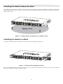
Installing the Switch without the Rack
When installing the Switch on a desktop or shelf, the rubber feet included with the Switch should first be attached. Attach these
cushioning feet on the bottom at each corner of the device. Allow enough ventilation space between the Switch and any other
objects in the vicinity.
Figure 2 - 1. Prepare Switch for installation on a desktop or shelf
Installing the Switch in a Rack
The Switch can be mounted in a standard 19" rack. Use the following diagrams to guide you.
Figure 2 - 2. Fasten mounting brackets to Switch
Fasten the mounting brackets to the Switch using the screws provided. With the brackets attached securely, users can mount the
Switch in a standard rack as shown in the next figure.
10
DES-3028 DES-3028P DES-3028G DES-3052 DES-3052P Layer 2 Fast Ethernet Managed Switch
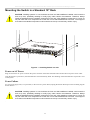
Mounting the Switch in a Standard 19" Rack
CAUTION: Installing systems in a rack without the front and side stabilizers installed could cause the
rack to tip over, potentially resulting in bodily injury under certain circumstances. Therefore, always
install the stabilizers before installing components in the rack. After installing components in a rack, do
not pull more than one component out of the rack on its slide assemblies at one time. The weight of
more than one extended component could cause the rack to tip over and may result in injury.
Figure 2 - 3. Installing Switch in a rack
Power on AC Power
Plug one end of the AC power cord into the power connector of the Switch and the other end into the local power source outlet.
After the Switch is powered on, the LED indicators will momentarily blink. This blinking of the LED indicators represents a reset
of the system.
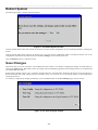
Power Failure
For AC power supply units, as a precaution, in the event of a power failure, unplug the Switch. When power has resumed, plug the
Switch back in.
CAUTION: Installing systems in a rack without the front and side stabilizers installed could cause the
rack to tip over, potentially resulting in bodily injury under certain circumstances. Therefore, always
install the stabilizers before installing components in the rack. After installing components in a rack, do
not pull more than one component out of the rack on its slide assemblies at one time. The weight of
more than one extended component could cause the rack to tip over and may result in injury.
.
11
DES-3028 DES-3028P DES-3028G DES-3052 DES-3052P Layer 2 Fast Ethernet Managed Switch
Section 3
Connecting the Switch
Switch to End Node
Switch to Hub or Switch
Connecting to Network Backbone or Server
NOTE: All 10/100/1000Mbps NWay Ethernet ports can support both MDIII and MDI-X connections.
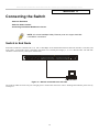
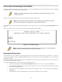
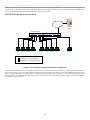
Switch to End Node
End nodes include PCs outfitted with a 10, 100 or 1000 Mbps RJ 45 Ethernet/Fast Ethernet Network Interface Card (NIC) and
most routers. An end node can be connected to the Switch via a twisted-pair Category 3, 4, or 5 UTP/STP cable. The end node
should be connected to any of the ports of the Switch.
Figure 3- 1. Switch connected to an end node
The Link/Act LEDs for each UTP port will light green or amber when the link is valid. A blinking LED indicates packet activity
on that port.
12
DES-3028 DES-3028P DES-3028G DES-3052 DES-3052P Layer 2 Fast Ethernet Managed Switch
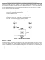
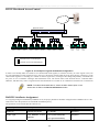
Switch to Hub or Switch
These connections can be accomplished in a number of ways using a normal cable.
A 10BASE-T hub or switch can be connected to the Switch via a twisted-pair Category 3, 4 or 5 UTP/STP cable.
A 100BASE-TX hub or switch can be connected to the Switch via a twisted-pair Category 5 UTP/STP cable.
A 1000BASE-T switch can be connected to the Switch via a twisted pair Category 5e UTP/STP cable.
A switch supporting a fiber-optic uplink can be connected to the Switch’s SFP ports via fiber-optic cabling.
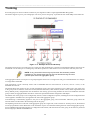
Figure 3- 2. Switch connected to a normal (non-Uplink) port on a hub or switch using a straight or crossover
cable
NOTICE: When the SFP transceiver acquires a link, the associated integrated
10/100/1000BASE-T port is disabled.
13
DES-3028 DES-3028P DES-3028G DES-3052 DES-3052P Layer 2 Fast Ethernet Managed Switch
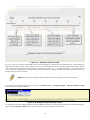
Section 4
Introduction to Switch Management
Management Options
Web-based Management Interface
SNMP-Based Management
Managing User Accounts
Command Line Console Interface through the Serial Port
Connecting the Console Port (RS-232 DCE)
First Time Connecting to the Switch
Password Protection
SNMP Settings
IP Address Assignment
Management Options
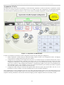
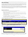
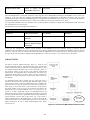
This system may be managed out-of-band through the console port on the front panel or in-band using Telnet. The user may also
choose the web-based management, accessible through a web browser.
Web-based Management Interface
After you have successfully installed the Switch, you can configure the Switch, monitor the LED panel, and display statistics
graphically using a web browser, such as Netscape Navigator (version 6.2.3 and higher) or Microsoft® Internet Explorer (version
6.0).
SNMP-Based Management
You can manage the Switch with an SNMP-compatible console program. The Switch supports SNMP version 1.0, version 2.0 and
version 3.0. The SNMP agent decodes the incoming SNMP messages and responds to requests with MIB objects stored in the
database. The SNMP agent updates the MIB objects to generate statistics and counters.
Connecting the Console Port (RS-232 DCE)
The Switch provides an RS-232 serial port that enables a connection to a computer or terminal for monitoring and configuring the
Switch. This port is a female DB-9 connector, implemented as a data terminal equipment (DTE) connection.
To use the console port, you need the following equipment:
A terminal or a computer with both a serial port and the ability to emulate a terminal.
A null modem or crossover RS-232 cable with a female DB-9 connector for the console port on the Switch.
To connect a terminal to the console port:
1.
Connect the female connector of the RS-232 cable directly to the console port on the Switch, and tighten the captive
retaining screws.
2.
Connect the other end of the cable to a terminal or to the serial connector of a computer running terminal emulation
software. Set the terminal emulation software as follows:
3.
Select the appropriate serial port (COM port 1 or COM port 2).
4.
Set the data rate to 9600 baud.
5.
Set the data format to 8 data bits, 1 stop bit, and no parity.
6.
Set flow control to none.
14
DES-3028 DES-3028P DES-3028G DES-3052 DES-3052P Layer 2 Fast Ethernet Managed Switch
7.
Under Properties, select VT100 for Emulation mode.
8.
Select Terminal keys for Function, Arrow, and Ctrl keys. Ensure that you select Terminal keys (not Windows keys).
NOTE: When you use HyperTerminal with the Microsoft® Windows® 2000 operating system, ensure that you have Windows 2000 Service Pack 2 or later installed. Windows 2000
Service Pack 2 allows you to use arrow keys in HyperTerminal's VT100 emulation. See
www.microsoft.com for information on Windows 2000 service packs.
9.
After you have correctly set up the terminal, plug the power cable into the power receptacle on the back of the Switch.
The boot sequence appears in the terminal.
10. After the boot sequence completes, the console login screen displays.
11. If you have not logged into the command line interface (CLI) program, press the Enter key at the User name and
password prompts. There is no default user name and password for the Switch. The administrator must first create user
names and passwords. If you have previously set up user accounts, log in and continue to configure the Switch.
12. Enter the commands to complete your desired tasks. Many commands require administrator-level access privileges. Read
the next section for more information on setting up user accounts. See the DES-3028/28P/28G/52/52P CLI Manual on
the documentation CD for a list of all commands and additional information on using the CLI.
13. When you have completed your tasks, exit the session with the logout command or close the emulator program.
14. Make sure the terminal or PC you are using to make this connection is configured to match these settings.
If you are having problems making this connection on a PC, make sure the emulation is set to VT-100. You will be able to set the
emulation by clicking on the File menu in you HyperTerminal window, clicking on Properties in the drop-down menu, and then
clicking the Settings tab. This is where you will find the Emulation options. If you still do not see anything, try rebooting the
Switch by disconnecting its power supply.
Once connected to the console, the screen below will appear on your console screen. This is where the user will enter commands
to perform all the available management functions. The Switch will prompt the user to enter a user name and a password. Upon
the initial connection, there is no user name or password and therefore just press enter twice to access the command line interface.
DES-3028G Fast Ethernet Switch Command Line Interface
Firmware: Build 2.00.B26
Copyright(C) 2009 D-Link Corporation. All rights reserved.
UserName:
Figure 4- 1. Initial screen after first connection
15
DES-3028 DES-3028P DES-3028G DES-3052 DES-3052P Layer 2 Fast Ethernet Managed Switch
First Time Connecting to the Switch
The Switch supports user-based security that can allow you to prevent unauthorized users from accessing the Switch or changing
its settings. This section tells how to log onto the Switch.
NOTE: The passwords used to access the Switch are case-sensitive; therefore, "S" is
not the same as "s."
When you first connect to the Switch, you will be presented with the first login screen.
NOTE: Press Ctrl+R to refresh the screen. This command can be used at any time to
force the console program in the Switch to refresh the console screen.
Press Enter in both the Username and Password fields. You will be given access to the command prompt DES-3028G:4# shown
below:
There is no initial username or password. Leave the Username and Password fields blank.
DES-3028G Fast Ethernet Switch Command Line Interface
Firmware: Build 2.00.B26
Copyright(C) 2009 D-Link Corporation. All rights reserved.
UserName:
PassWord:
DES-3028G:4#
Figure 4- 2. Command Prompt
NOTE: The first user automatically gets Administrator level privileges. It is recommended to
create at least one Admin-level user account for the Switch.
Password Protection
The Switch does not have a default user name and password. One of the first tasks when settings up the Switch is to create user
accounts. Once logged in using a predefined administrator-level user name, users will have privileged access to the Switch's
management software.
After your initial login, define new passwords for both default user names to prevent unauthorized access to the Switch, and
record the passwords for future reference.
To create an administrator-level account for the Switch, follow these steps:
At the CLI login prompt, enter create account admin followed by the <user name> and press the Enter key.
The switch will then prompt the user for a password. Type the <password> used for the administrator account being
created and press the Enter key.
Again, the user will be prompted to enter the same password again to verify it. Type the same password and press
the Enter key.
Successful creation of the new administrator account will be verified by a Success message.
16
DES-3028 DES-3028P DES-3028G DES-3052 DES-3052P Layer 2 Fast Ethernet Managed Switch
NOTE: Passwords are case sensitive. User names and passwords can be
up to 15 characters in length.
The sample below illustrates a successful creation of a new administrator-level account with the user name "newmanager".
DES-3028G:4# create account admin newmanager
Command: create account admin newmanager
Enter a case-sensitive new password: ********
Enter the new password again for confirmation: ********
Success.
DES-3028G:4#
Figure 4- 3. Create account command
NOTICE: CLI configuration commands only modify the running configuration file
and are not saved when the Switch is rebooted. To save all your configuration
changes in nonvolatile storage, you must use the save command to copy the
running configuration file to the startup configuration.
NOTICE: In case of lost passwords or password corruption, please refer to the
Appendix D of this manual entitled “Password Recovery Procedure”, which will
guide you through the steps necessary to resolve this issue.
SNMP Settings
Simple Network Management Protocol (SNMP) is an OSI Layer 7 (Application Layer) designed specifically for managing and
monitoring network devices. SNMP enables network management stations to read and modify the settings of gateways, routers,
switches, and other network devices. Use SNMP to configure system features for proper operation, monitor performance and
detect potential problems in the Switch, switch group or network.
Managed devices that support SNMP include software (referred to as an agent), which runs locally on the device. A defined set of
variables (managed objects) is maintained by the SNMP agent and used to manage the device. These objects are defined in a
Management Information Base (MIB), which provides a standard presentation of the information controlled by the on-board
SNMP agent. SNMP defines both the format of the MIB specifications and the protocol used to access this information over the
network.
The DES-3028/28P/28G/52/52P supports SNMP versions 1, 2c, and 3. You can specify which version of SNMP you want to use
to monitor and control the Switch. The three versions of SNMP vary in the level of security provided between the management
station and the network device.
In SNMP v.1 and v.2, user authentication is accomplished using 'community strings', which function like passwords. The remote
user SNMP application and the Switch SNMP must use the same community string. SNMP packets from any station that has not
been authenticated are ignored (dropped).
The default community strings for the Switch used for SNMP v.1 and v.2 management access are:
public - Allows authorized management stations to retrieve MIB objects.
private - Allows authorized management stations to retrieve and modify MIB objects.
SNMP v.3 uses a more sophisticated authentication process that is separated into two parts. The first part is to maintain a list of
users and their attributes that are allowed to act as SNMP managers. The second part describes what each user on that list can do
as an SNMP manager.
The Switch allows groups of users to be listed and configured with a shared set of privileges. The SNMP version may also be set
for a listed group of SNMP managers. Thus, you may create a group of SNMP managers that are allowed to view read-only
17
DES-3028 DES-3028P DES-3028G DES-3052 DES-3052P Layer 2 Fast Ethernet Managed Switch
information or receive traps using SNMP v.1 while assigning a higher level of security to another group, granting read/write privileges using SNMP v.3.
Using SNMP v.3 individual users or groups of SNMP managers can be allowed to perform or be restricted from performing
specific SNMP management functions. The functions allowed or restricted are defined using the Object Identifier (OID)
associated with a specific MIB. An additional layer of security is available for SNMP v.3 in that SNMP messages may be
encrypted. To read more about how to configure SNMP v.3 settings for the Switch read the section entitled Management.
Traps
Traps are messages that alert network personnel of events that occur on the Switch. The events can be as serious as a reboot
(someone accidentally turned OFF the Switch), or less serious like a port status change. The Switch generates traps and sends
them to the trap recipient (or network manager). Typical traps include trap messages for Authentication Failure, Topology Change
and Broadcast\Multicast Storm.
MIBs
The Switch in the Management Information Base (MIB) stores management and counter information. The Switch uses the
standard MIB-II Management Information Base module. Consequently, values for MIB objects can be retrieved from any SNMPbased network management software. In addition to the standard MIB-II, the Switch also supports its own proprietary enterprise
MIB as an extended Management Information Base. Specifying the MIB Object Identifier may also retrieve the proprietary MIB.
MIB values can be either read-only or read-write.
IP Address Assignment
Each Switch must be assigned its own IP Address, which is used for communication with an SNMP network manager or other
TCP/IP application (for example BOOTP, TFTP). The Switch's default IP address is 10.90.90.90. You can change the default
Switch IP address to meet the specification of your networking address scheme.
The Switch is also assigned a unique MAC address by the factory. This MAC address cannot be changed, and can be found by
entering the command "show switch" into the command line interface, as shown below.
18
DES-3028 DES-3028P DES-3028G DES-3052 DES-3052P Layer 2 Fast Ethernet Managed Switch
DES-3028G:4#show switch
Command: show switch
Device Type
MAC Address
IP Address
VLAN Name
Subnet Mask
Default Gateway
Boot PROM Version
Firmware Version
Hardware Version
Serial Number
System Name
System Location
System Contact
Spanning Tree
GVRP
IGMP Snooping
VLAN trunk
802.1X
TELNET
WEB
RMON
SSH
:
:
:
:
:
:
:
:
:
:
:
:
:
:
:
:
:
:
:
:
:
:
DES-3028G Fast Ethernet Switch
00-21-91-98-60-77
10.73.21.11 (Manual)
default
255.0.0.0
0.0.0.0
Build 1.00.B06
Build 2.00.B26
A1
P4IG188000007
Disabled
Disabled
Disabled
Disabled
Disabled
Enabled(TCP
Enabled(TCP
Disabled
Disabled
23)
80)
CTRL+C ESC q Quit SPACE n Next Page ENTER Next Entry a All
Figure 4- 4. Show switch command
The Switch's MAC address can also be found from the Web management program on the Switch Information (Basic Settings)
window on the Configuration menu.
The IP address for the Switch must be set before it can be managed with the Web-based manager. The Switch IP address can be
automatically set using BOOTP or DHCP protocols, in which case the actual address assigned to the Switch must be known.
The IP address may be set using the Command Line Interface (CLI) over the console serial port as follows:
Starting at the command line prompt, enter the commands
config ipif System ipaddress xxx.xxx.xxx.xxx/yyy.yyy.yyy.yyy
Where the x's represent the IP address to be assigned to the IP interface named System and the y's represent the corresponding
subnet mask.
Alternatively, you can enter config ipif System ipaddress xxx.xxx.xxx.xxx/z. Where the x's represent the IP address to be
assigned to the IP interface named System and the z represents the corresponding number of subnets in CIDR notation.
The IP interface named System on the Switch can be assigned an IP address and subnet mask, and then be used to connect a
management station to the Switch's Telnet or Web-based management agent.
19
DES-3028 DES-3028P DES-3028G DES-3052 DES-3052P Layer 2 Fast Ethernet Managed Switch
DES-3028G:4#config ipif System ipaddress 10.90.90.91/255.0.0.0
Command: config ipif System ipaddress 10.90.90.91/8
Success.
DES-3028G:4#
Figure 4- 5. Assigning the Switch an IP Address
In the above example, the Switch was assigned an IP address of 10.90.90.91 with a subnet mask of 255.0.0.0. (the CIDR form was
used to set the address (10.90.90.91/8). The system message Success indicates that the command was executed successfully. The
Switch can now be configured and managed via Telnet and the CLI or via the Web-based management.
20
DES-3028 DES-3028P DES-3028G DES-3052 DES-3052P Layer 2 Fast Ethernet Managed Switch
Section 5
Web-based Switch Configuration
Introduction
Login to Web manager
Web-Based User Interface
Basic Setup
Reboot
Basic Switch Setup
Network Management
Switch Utilities
Network Monitoring
IGMP Snooping Status
Introduction
All software functions of the Switch can be managed, configured and monitored via the embedded web-based (HTML) interface.
The Switch can be managed from remote stations anywhere on the network through a standard browser such as Opera, Netscape
Navigator/Communicator, or Microsoft Internet Explorer. The browser acts as a universal access tool and can communicate
directly with the Switch using the HTTP protocol.
The Web-based management module and the Console program (and Telnet) are different ways to access the same internal
switching software and configure it. Thus, all settings encountered in web-based management are the same as those found in the
console program.
Login to Web Manager
To begin managing the Switch, simply run the browser you have installed on your computer and point it to the IP address you
have defined for the device. The URL in the address bar should read something like: http://123.123.123.123, where the numbers
123 represent the IP address of the Switch.
NOTE: The Factory default IP address for the Switch is 10.90.90.90.
This opens the management module's user authentication window, as seen below.
21
DES-3028 DES-3028P DES-3028G DES-3052 DES-3052P Layer 2 Fast Ethernet Managed Switch
Figure 5- 1. Enter Network Password dialog
Enter “admin” in both the User Name and Password fields and click OK. This will open the Web-based user interface. The Switch
management features available in the web-based manager are explained below.
Web-based User Interface
The user interface provides access to various Switch configuration and management windows, allows you to view performance
statistics, and permits you to graphically monitor the system status.
Areas of the User Interface
The figure below shows the user interface. The user interface is divided ito three distinct areas as described in the table.
22
DES-3028 DES-3028P DES-3028G DES-3052 DES-3052P Layer 2 Fast Ethernet Managed Switch
Area 2
Area 1
Figure 5- 2. Main Web-Manager page
Area
Function
Area 1
Select the folder or window to be displayed. The folder icons can be opened to display the hyperlinked window buttons and subfolders contained within them. Click the D-Link logo to go to the DLink website.
Area 2
Presents a graphical near real-time image of the front panel of the Switch. This area displays the
Switch's ports and expansion modules, showing port activity, duplex mode, or flow control,
depending on the specified mode.
Various areas of the graphic can be selected for performing management functions, including port
configuration.
Area 3
Presents switch information based on your selection and the entry of configuration data.
NOTICE: Any changes made to the Switch configuration during the current
session must be saved in the Save Changes web menu (explained below)
or use the command line interface (CLI) command save.
23
DES-3028 DES-3028P DES-3028G DES-3052 DES-3052P Layer 2 Fast Ethernet Managed Switch
Web Pages
When you connect to the management mode of the Switch with a web browser, a login window is displayed. Enter a user name
and password to access the Switch's management mode.
Below is a list and description of the main folders available in the web interface:
Administration – Contains windows concerning configuring the basic functions of the Switch, including Device Information, IP
Address, Port Configuration, DHCP/BOOTP Relay, User Accounts, Cable Diagnostics, Port Mirroring, System Log Settings, Log
Settings, SNTP Settings, MAC Notification Settings, TFTP Services, Multiple Image Services, Ping Test, Safeguard Engine,
SNMP Manager, PoE System, Single IP Settings, Forwarding & Filtering, and SMTP Service.
Layer 2 Features – Contains windows concerning Layer 2 features of the Switch, including VLAN, QinQ, Trunking, IGMP
Snooping, MLD Snooping, Spanning Tree, Loopback Detection and LLDP.
CoS – Contains windows concerning Port Bandwidth, 802.1P Default Priority, 802.1P User Priority, CoS Scheduling Mechanism,
CoS Output Scheduling, Priority Settings, TOS Priority Settings, DSCP Priority Settings, Port Mapping Priority Settings, and
MAC Priority.
ACL – Contains the windows for Time Range, Access Profile Table and CPU Interface Filtering.
Security – Contains windows for Traffic Control, Port Security, Port Lock Entries, IP-MAC-Port Binging, SSL, SSH, 802.1X,
Trusted Host, Access Authentication Control, Traffic Segmentation and DoS Attack Prevention.
Monitoring – Contains windows for including CPU Utilization, Port Utilization, Packets, Packet Errors, Packet Size, MAC
Address, Switch Log, IGMP Snooping Group, Browse Router Port, VLAN Status, MLD Snooping Group, Browse MLD
Snooping Router Port, Static ARP Settings, ARP-FDB, Gratuitous ARP Settings, Session Table, and Port Access Control.
Switch Maintenance – Contains information regarding Reset, Reboot System, Save Changes, and Logout.
NOTE: Be sure to configure the user name and password in the User
Accounts window before connecting the Switch to the greater network.
24
DES-3028 DES-3028P DES-3028G DES-3052 DES-3052P Layer 2 Fast Ethernet Managed Switch
Section 6
Administration
IP Address
Port Configuration
DHCP/BOOTP Relay
User Accounts
Cable Diagnostics
Port Mirroring
System Log Settings
Log Settings
SNTP Settings
MAC Notification Settings
TFTP Services
Multiple Image Services
Ping Test
Safeguard Engine
SNMP Manager
PoE System
Single IP Settings
Forwarding & Filtering
SMTP Service
25
DES-3028 DES-3028P DES-3028G DES-3052 DES-3052P Layer 2 Fast Ethernet Managed Switch
Device Information
This window contains the main settings for all major
functions of the Switch and appears automatically when
you log on. To return to the Device Information window,
click the DES-30xx Web Management Tool folder. The
Device Information window shows the Switch’s MAC
Address (assigned by the factory and unchangeable), the
Boot PROM, Firmware Version, Hardware Version
and Serial Number. This information is helpful to keep
track of PROM and firmware updates and to obtain the
Switch's MAC address for entry into another network
device's address table, if necessary. The user may also
enter a System Name, System Location and System
Contact to aid in defining the Switch. In addition, this
window displays the status of functions on the Switch to
quickly assess their current global status. Some functions
are hyper-linked to their configuration window for easy
access from the Device Information window.
Figure 6- 1. Device Information window
26
DES-3028 DES-3028P DES-3028G DES-3052 DES-3052P Layer 2 Fast Ethernet Managed Switch
The fields that can be configured are described below:
Parameter
Description
System Name
Enter a system name for the Switch, if so desired. This name will identify it in the Switch
network.
System Location
Enter the location of the Switch, if so desired.
System Contact
Enter a contact name for the Switch, if so desired.
Serial Port Auto
Logout Time
Select the logout time used for the console interface. This automatically logs the user out after
an idle period of time, as defined. Choose from the following options: 2 Minutes, 5 Minutes, 10
Minutes, 15 Minutes or Never. The default setting is 10 minutes.
Serial Port Baud Rate
This field specifies the baud rate for the serial port on the Switch. there are four possible baud
rates to choose from, 9600, 19200, 38400 and 115200. For a connection to the Switch using
the CLI interface, the baud rate must be set to 9600, which is the default setting.
MAC Address Aging
Time
This field specifies the length of time a learned MAC Address will remain in the forwarding
table without being accessed (that is, how long a learned MAC Address is allowed to remain
idle). To change this, type in a different value representing the MAC address age-out time in
seconds. The MAC Address Aging Time can be set to any value between 10 and 1,000,000
seconds. The default setting is 300 seconds.
IGMP Snooping
To enable system-wide IGMP Snooping capability select Enabled. IGMP snooping is Disabled
by default. Enabling IGMP snooping allows you to specify use of a multicast router only (see
below). To configure IGMP Snooping for individual VLANs, use the IGMP Snooping window
located in the IGMP Snooping folder contained in the L2 Features folder.
Multicast Router Only
This field specifies that the Switch should only forward all multicast traffic to a multicastenabled router, if enabled. Otherwise, the Switch will forward all multicast traffic to any IP
router. The default is Disabled.
MLD Snooping
This field specifies the status of MLD Snooping on the Switch. MLD Snooping is used to
discover ports on a VLAN that are requesting multicast data instead of flooding all ports on a
selected VLAN with multicast traffic. The default is Disabled.
Telnet Status
Telnet configuration is Enabled by default. If you do not want to allow configuration of the
system through Telnet choose Disabled.
Telnet TCP Port
Number (1-65535)
The TCP port number. TCP ports are numbered between 1 and 65535. The "well-known" TCP
port for the Telnet protocol is 23.
Web Status
Web-based management is Enabled by default. If you choose to disable this by selecting
Disabled, you will lose the ability to configure the system through the web interface as soon as
these settings are applied.
Web TCP Port Number
(1-65535)
The TCP port number. TCP ports are numbered between 1 and 65535. The "well-known" TCP
port for the Web is 80.
RMON Status
Remote monitoring (RMON) of the Switch is Enabled or Disabled here.
Link Aggregation
Algorithm
The algorithm that the Switch uses to balance the load across the ports that make up the port
trunk group is defined by this definition. Choose MAC Source, MAC Destination, MAC Src &
Dest, (See the Link Aggregation section of this manual).
Switch 802.1X
MAC Address can be enabled by port or by the Switch’s 802.1X function; the default is
Disabled. This field must be enabled to view and configure certain windows for 802.1X. More
information regarding 802.1X, its functions and implementation can be found later in this
manual, under Monitoring > Port Access Control.
Port-Based 802.1X specifies that ports configured for 802.1X are initialized based on the port
number only and are subject to any authorization parameters configured.
MAC-based 802.1X specifies Host-based authentication with which the ports configured for
802.1X are initialized based on the MAC address of the computer being authenticated.
27
DES-3028 DES-3028P DES-3028G DES-3052 DES-3052P Layer 2 Fast Ethernet Managed Switch
NOTE: If you want to configure Host-based 802.1X please select
MAC-based 802.1X instead.
Auth Protocol
The 802.1X authentication protocol on the Switch is set to RADIUS Eap and cannot be
altered.
Syslog Status
Enables or disables Syslog State; default is Disabled.
Port Security Trap Log
Toggle this setting to enable or disable the port security trap log feature. The default is
Disabled.
ARP Aging Time (065535)
The user may globally set the maximum amount of time, in minutes, an Address Resolution
Protocol (ARP) entry can remain in the Switch’s ARP table, without being accessed, before it
is dropped from the table. The value may be set in the range of 0 to 65535 minutes with a
default setting of 20 minutes.
GVRP
Use this pull-down menu to Enable or Disable GVRP on the Switch.
VLAN Trunk
Use this pull-down menu to Enable or Disable VLAN Trunk on the Switch.
Multicast VLAN
Use this pull-down menu to Enable or Disable Multicast VLAN on the Switch.
Asymmetric VLAN
Use this pull-down menu to Enable or Disable Asymmetric VLAN on the Switch.
Password Encryption
Use this pull-down menu to Enable or Disable Password Encryption on the Switch.
Password encryption allows the user to encrypt a password for additional security. Select
enable to change the password into encrypted form. When password encryption is disabled,
the user can specify that the password be in plain text form or in encrypted form. If the
password has been converted to encrypted form, the password will stay in encrypted form and
cannot be reverted back to plaintext form.
DoS Attack Prevention
Trap Log
Use this pull-down menu to Enable or Disable DoS Attack Prevention Trap Log on the Switch.
Click Apply to implement changes made.
IP Address
The IP address may initially be set using the console interface prior to connecting to it through the Ethernet. If the Switch IP
address has not yet been changed, read the introduction of the DES-3028/28P/28G/52/52P CLI Manual or return to Section 4 of
this manual for more information. To change IP settings using the web manager click Administration > IP Address the
following window will be displayed.
To configure the Switch's IP address:
Figure 6- 2. IP Address Settings window
To manually assign the Switch's IP address, subnet mask, and default gateway address:
1.
Select Manual from the Get IP From drop-down menu.
28
DES-3028 DES-3028P DES-3028G DES-3052 DES-3052P Layer 2 Fast Ethernet Managed Switch
2.
Enter the appropriate IP Address and Subnet Mask.
3.
If you want to access the Switch from a different subnet from the one it is installed on, enter the IP address of the Default
Gateway. If you will manage the Switch from the subnet on which it is installed, you can leave the default address
(0.0.0.0) in this field.
4.
If no VLANs have been previously configured on the Switch, you can use the default VLAN Name. The default VLAN
contains all of the Switch ports as members. If VLANs have been previously configured on the Switch, you will need to
enter the VLAN Name of the VLAN that contains the port connected to the management station that will access the
Switch. The Switch will allow management access from stations in the same VLAN.
NOTE: The Switch's factory default IP address is 10.90.90.90 with a
subnet mask of 255.0.0.0 and a default gateway of 0.0.0.0.
To use the BOOTP or DHCP protocols to assign the Switch an IP address, subnet mask, and default gateway address:
Use the Get IP From pull-down menu to choose from BOOTP or DHCP. This selects how the Switch will be assigned an IP
address on the next reboot.
The IP Address Settings options are:
Parameter
Description
BOOTP
The Switch will send out a BOOTP broadcast request when it is powered up. The BOOTP
protocol allows IP addresses, network masks, and default gateways to be assigned by a central
BOOTP server. If this option is set, the Switch will first look for a BOOTP server to provide it with
this information before using the default or previously entered settings.
DHCP
The Switch will send out a DHCP broadcast request when it is powered on. The DHCP protocol
allows IP addresses, network masks, and default gateways to be assigned by a DHCP server. If
autoconfig is enabled, the Switch will first look for a DHCP server to provide it with information
before using the default or previously entered settings.
Manual
Allows the entry of an IP address, Subnet Mask, and a Default Gateway for the Switch. These
fields should be of the form xxx.xxx.xxx.xxx, where each xxx is a number (represented in decimal
form) between 0 and 255. This address should be a unique address on the network assigned for
use by the network administrator.
Subnet Mask
A Bitmask that determines the extent of the subnet that the Switch is on. Should be of the form
xxx.xxx.xxx.xxx, where each xxx is a number (represented in decimal) between 0 and 255. The
value should be 255.0.0.0 for a Class A network, 255.255.0.0 for a Class B network, and
255.255.255.0 for a Class C network, but custom subnet masks are allowed.
Default Gateway
IP address that determines where packets with a destination address outside the current subnet
should be sent. This is usually the address of a router or a host acting as an IP gateway. If your
network is not part of an intranet, or you do not want the Switch to be accessible outside your
local network, you can leave this field unchanged.
VLAN Name
This allows the entry of a VLAN Name from which a management station will be allowed to
manage the Switch using TCP/IP (in-band via web manager or Telnet). Management stations that
are on VLANs other than the one entered here will not be able to manage the Switch in-band
unless their IP addresses are entered in the Security IP Management window. If VLANs have
not yet been configured for the Switch, the default VLAN contains all of the Switch's ports. There
are no entries in the Security IP Management table, by default, so any management station that
can connect to the Switch can access the Switch until a management VLAN is specified or
Management Station IP Addresses are assigned.
Auto Config
State
When autoconfig is Enabled, the Switch is instructed to get a configuration file via TFTP, and it
becomes a DHCP client automatically. The configuration file will be loaded upon booting up. In
order to use Auto Config, the DHCP server must be set up to deliver the TFTP server IP address
and configuration file name information in the DHCP reply packet. The TFTP server must be
running and have the requested configuration file stored in its base directory when the request is
received from the Switch. Consult the DHCP server and/or TFTP server software instructions for
information on loading a configuration file for use by a client.
If the Switch is unable to complete the autoconfiguration process the previously saved
29
DES-3028 DES-3028P DES-3028G DES-3052 DES-3052P Layer 2 Fast Ethernet Managed Switch
configuration file present in Switch memory will be loaded.
Click Apply to allow changes to take effect.
Setting the Swith’s IP Address using the Console Interface
Each Switch must be assigned its own IP Address, which is used for communication with an SNMP network manager or other
TCP/IP application (for example BOOTP, TFTP). The Switch’s default IP address is 10.90.90.90. You can change the default
Switch IP address to meet the specification of your networking address scheme.
The IP address for the Switch must be set before it can be managed with the Web-based manager. The Switch IP address can be
automatically set using BOOTP or DHCP protocols, in which case the actual address assigned to the Switch must be known. The
IP address may be set using the Command Line Interface (CLI) over the console serial port as follows:
Starting at the command line prompt, enter the commands config ipif System ipaddress xxx.xxx.xxx.xxx/yyy.yyy.yyy.yyy,
where the x’s represent the IP address to be assigned to the IP interface named System and the y’s represent the corresponding
subnet mask.
Alternatively, you can enter config ipif System ipaddress xxx.xxx.xxx.xxx/z, where the x’s represents the corresponding number
of subnets in CIDR notation.
The IP interface named System on the Switch can be assigned an IP address and subnet mask which can then be used to connect a
management station to the Switch’s Telnet or Web-based management agent.
The system message Success indicated that the command was executed successfully. The Switch can now be configured and
managed via Telnet and the CLI or via the Web-based management agent using the above ip address to connect to the Switch.
30
DES-3028 DES-3028P DES-3028G DES-3052 DES-3052P Layer 2 Fast Ethernet Managed Switch
Port Configuration
This section contains information for configuring various attributes and properties for individual physical ports, including port
speed and flow control.
Port Settings
Click Administration > Port Configuration > Port Settings to display the following window:
To configure switch ports:
1.
Choose the port or sequential range of ports using the From…To… port pull-down menus.
Use the remaining pull-down menus to configure the parameters described below:
Figure 6- 3. Port Configuration window
31
DES-3028 DES-3028P DES-3028G DES-3052 DES-3052P Layer 2 Fast Ethernet Managed Switch
The following parameters can be configured:
Parameter
Description
From…. To
Use the pull-down menus to select the port or range of ports to be configured.
State
Toggle this field to either enable or disable a given port or group of ports.
Speed/Duplex
Toggle the Speed/Duplex field to either select the speed and duplex state of the port. Auto
denotes auto-negotiation between 10 and 100 Mbps devices, in full- or half-duplex. The Auto
setting allows the port to automatically determine the fastest settings the device the port is
connected to can handle, and then to use those settings. The other options are 10M/Half,
10M/Full, 100M/Half and 100M/Full, 1000M/Full_M and 1000M/Full_S. There is no automatic
adjustment of port settings with any option other than Auto. The fiber port Speed/Duplex only
supports Auto and 1000M/Full.
The Switch allows the user to configure two types of gigabit connections; 1000M/Full_M and
1000M/Full_S. Gigabit connections only support full duplex connections and take on certain
characteristics that are different from the other choices listed.
The 1000M/Full_M (master) and 1000M/Full_S (slave) parameters refer to connections running
a 1000BASE-T cable for connection between the Switch port and other device capable of a
gigabit connection. The master setting (1000M/Full_M) will allow the port to advertise capabilities
related to duplex, speed and physical layer type. The master setting will also determine the
master and slave relationship between the two connected physical layers. This relationship is
necessary for establishing the timing control between the two physical layers. The timing control
is set on a master physical layer by a local source. The slave setting (1000M/Full_S) uses loop
timing, where the timing comes from a data stream received from the master. If one connection
is set for 1000M/Full_M, the other side of the connection must be set for 1000M/Full_S. Any
other configuration will result in a link down status for both ports.
Flow Control
Displays the flow control scheme used for the various port configurations. Ports configured for
full-duplex use 802.3x flow control, half-duplex ports use backpressure flow control, and Auto
ports use an automatic selection of the two. The default is Disabled.
Medium Type
This applies only to the Combo ports. If configuring the Combo ports this defines the type of
transport medium being configured. SFP ports should be set at Fiber and the Combo
1000BASE-T ports should be set at Copper if no medium type is specified the device will
assume the Copper port is the one being configured.
MDIX
MDIX can be set to Auto, Normal and Cross depending on the cable type used for the
connection.
Learning
When Enabled, destination and source MAC addresses are automatically listed in the forwarding
table. The default setting is Enabled.
Click Apply to implement the new settings on the Switch.
32
DES-3028 DES-3028P DES-3028G DES-3052 DES-3052P Layer 2 Fast Ethernet Managed Switch
Port Description
The Switch supports a port description feature
where the user may name various ports on the
Switch. To assign names to various ports, click
Administration > Port Configuration > Port
Description to view the following window:
Use the From and To pull-down menu to choose a
port or range of ports to describe, and then enter a
description of the port(s). Click Apply to set the
descriptions in the Port Description Table.
The Medium Type applies only to the Combo
ports. If configuring the Combo ports this defines
the type of tranport medium being configured. SFP
ports should be nominated Fiber and the Combo
1000BASE-T ports should be nominated Copper.
The result will be displayed in the appropriate
switch port number slot (C for copper ports and F
for fiber ports).
Figure 6- 4. Port Description window
Port Error Disabled
The following window will display the information about ports that have had their connection status disabled, for reasons such as
STP loopback detection or link down status. To view this window, click Administration > Port Configuration > Port Error
Disabled.
Figure 6- 5. Port Error Disabled window
The following parameters are displayed:
33
DES-3028 DES-3028P DES-3028G DES-3052 DES-3052P Layer 2 Fast Ethernet Managed Switch
Parameter
Description
Port
Displays the port that has been error disabled.
State
Describes the current running state of the port, whether Enabled or Disabled.
Connection
This field will show if a port has been disabled due to an error detected in the port.
Reason
Describes the reason why the port has been error-disabled, such as a STP loopback
occurrence.
Description
This field further describes the specifics of the action.
34
DES-3028 DES-3028P DES-3028G DES-3052 DES-3052P Layer 2 Fast Ethernet Managed Switch
DHCP/BOOTP Relay
To enable and configure DHCP/BOOTP Relay Global Settings on the Switch, click Administration > DHCP/BOOTP Relay >
DHCP/BOOTP Relay Global Settings:
DHCP/BOOTP Relay Global Settings
Figure 6- 6. DHCP/ BOOTP Relay Global Settings window
The following fields can be set:
Parameter
Description
BOOTP Relay State
This field can be toggled between Enabled and Disabled using the pull-down menu. It is
used to enable or disable the DHCP/BOOTP Relay service on the Switch. The default is
Disabled
BOOTP Relay Hops
Count Limit (1-16)
This field allows an entry between 1 and 16 to define the maximum number of relay hops
DHCP/BOOTP messages can be forwarded across. The default hop count is 4.
BOOTP Relay Time
Threshold (0-65535)
Allows an entry between 0 and 65535 seconds, and defines the maximum time limit for
routing a DHCP/BOOTP packet. If a value of 0 is entered, the Switch will not process the
value in the seconds field of the BOOTP or DHCP packet. If a non-zero value is entered,
the Switch will use that value, along with the hop count to determine whether to forward a
given BOOTP or DHCP packet.
DHCP Relay Agent
Information Option 82
State
This field can be toggled between Enabled and Disabled using the pull-down menu. It is
used to enable or disable the DHCP Agent Information Option 82 on the Switch. The default
is Disabled.
Enabled – When this field is toggled to Enabled the relay agent will insert and remove
DHCP relay information (option 82 field) in messages between DHCP servers and clients.
When the relay agent receives the DHCP request, it adds the option 82 information, and the
IP address of the relay agent (if the relay agent is configured), to the packet. Once the
option 82 information has been added to the packet it is sent on to the DHCP server. When
the DHCP server receives the packet, if the server is capable of option 82, it can implement
policies like restricting the number of IP addresses that can be assigned to a single remote
ID or circuit ID. Then the DHCP server echoes the option 82 field in the DHCP reply. The
DHCP server unicasts the reply to the back to the relay agent if the request was relayed to
the server by the relay agent. The switch verifies that it originally inserted the option 82
data. Finally, the relay agent removes the option 82 field and forwards the packet to the
switch port that connects to the DHCP client that sent the DHCP request.
Disabled - If the field is toggled to Disabled the relay agent will not insert and remove DHCP
relay information (option 82 field) in messages between DHCP servers and clients, and the
35
DES-3028 DES-3028P DES-3028G DES-3052 DES-3052P Layer 2 Fast Ethernet Managed Switch
check and policy settings will have no effect.
DHCP Relay Agent
Information Option 82
Check
This field can be toggled between Enabled and Disabled using the pull-down menu. It is
used to enable or disable the Switches ability to check the validity of the packet’s option 82
field.
Enabled – When the field is toggled to Enable, the relay agent will check the validity of the
packet’s option 82 field. If the switch receives a packet that contains the option-82 field from
a DHCP client, the switch drops the packet because it is invalid. In packets received from
DHCP servers, the relay agent will drop invalid messages.
Disabled - When the field is toggled to Disabled, the relay agent will not check the validity of
the packet’s option 82 field.
DHCP Relay Agent
Information Option 82
Policy
This field can be toggled between Replace, Drop, and Keep by using the pull-down menu.
It is used to set the Switches policy for handling packets when the DHCP Agent
Information Option 82 Check is set to Disabled. The default is Replace.
Replace - The option 82 field will be replaced if the option 82 field already exists in the
packet received from the DHCP client.
Drop - The packet will be dropped if the option 82 field already exists in the packet received
from the DHCP client.
Keep -The option 82 field will be retained if the option 82 field already exists in the packet
received from the DHCP client.
DHCP Relay Agent
Information Option 82
Remote ID
This field specifies the feature which allows the user to configure the Remote ID as any
specific string. When the Remote ID state is set to Default, the switch’s system MAC
address is used as the Remote ID. When the Remote ID state is configured to be userdefined, the user-defined string is used as the Remote ID.
Note: The maximum number of characters that can be used is 32.
Click Apply to implement any changes that have been made.
NOTE: If the Switch receives a packet that contains the option-82 field from a DHCP client and the
information-checking feature is enabled, the switch drops the packet because it is invalid. However, in
some instances, you might configure a client with the option-82 field. In this situation, you should
disable the information-check feature so that the switch does not remove the option-82 field from the
packet. You can configure the action that the switch takes when it receives a packet with existing
option-82 information by configuring the DHCP Agent Information Option 82 Policy.
36
DES-3028 DES-3028P DES-3028G DES-3052 DES-3052P Layer 2 Fast Ethernet Managed Switch
The Implementation of DHCP Information Option 82 in the DES-3028/28P/28G/52/52P
switches
The config dhcp_relay option_82 command configures the DHCP relay agent information option 82 setting of the switch. The
formats for the circuit ID sub-option and the remote ID sub-option are as follows:
NOTE: For the circuit ID sub-option of a standalone switch, the module field is always zero.
Circuit ID sub-option format:
1.
2.
3.
1
1 byte
4.
5.
6
0
4
1 byte
1 byte
1 byte
6.
VLAN
7.
Module
2 bytes
1 byte
Port
1 byte
1.
Sub-option type
2.
Length
3.
Circuit ID type
4.
Length
5.
VLAN : the incoming VLAN ID of DHCP client packet.
6.
Module : For a standalone switch, the Module is always 0; For a stackable switch, the Module is the Unit ID.
7.
Port : The incoming port number of DHCP client packet, port number starts from 1.
Remote ID sub-option format 1:
1.
2.
3.
2
4.
8
1 byte
0
1 byte
1 byte
5.
6
MAC address
1 byte
6 bytes
1.
Sub-option type
2.
Length
3.
Remote ID type
4.
Length
5.
MAC address: The Switch’s system MAC address.
Figure 6- 7. Circuit ID and Remote ID Sub-option Format 1
Remote ID sub-option format 2:
1.
2.
2
n+2
1 byte
1 byte
1.
3.
4.
1
1 byte
5.
n
User-defined String
1 byte
6 bytes
Sub-option type
37
DES-3028 DES-3028P DES-3028G DES-3052 DES-3052P Layer 2 Fast Ethernet Managed Switch
2.
Length: the string length of the Remote ID suboption
3.
Remote ID type
4.
Length: the string length of the user-defined string
5.
User-defined string
Figure 6- 8. Circuit ID and Remote ID Sub-option Format 2
DHCP/BOOTP Relay Interface Settings
This window allows the user to set up a server, by IP address, for relaying DHCP/ BOOTP information to the Switch. The user
may enter a previously configured IP interface on the Switch that will be connected directly to the DHCP/BOOTP server using the
following window. Properly configured settings will be displayed in the BOOTP Relay Table at the bottom of the following
window, once the user clicks the Add button under the Apply heading. The user may add up to four server IPs per IP interface on
the Switch. Entries may be deleted by clicking it’s corresponding . To enable and configure DHCP/BOOTP Relay Interface
Settings on the Switch, click Administration > DHCP/BOOTP Relay > DHCP/BOOTP Relay Interface Settings:
Figure 6- 9. DHCP/BOOTP Relay Interface Settings and DHCP/BOOTP Relay Interface Table window
The following parameters may be configured or viewed.
Parameter
Description
Interface
The IP interface on the Switch that will be connected directly to the Server.
Server IP
Enter the IP address of the DHCP/BOOTP server. Up to four server IPs can be configured
per IP Interface
DHCP Local Relay Settings
The DHCP Local Relay Settings are used on request packets from the Client to the Server. As a result of the customer’s
networking environment, DCHP Local Relay is implemented so that it is independent from the original behavior of DHCP relay.
The DHCP Local Relay is also independent from the option82 module in the forwarding way and the content of DHCP request
packets from Client to Server.
To enable and configure DHCP Local Relay Global Settings on the Switch, click Administration > DHCP/BOOTP Relay >
DHCP Local Relay Settings:
38
DES-3028 DES-3028P DES-3028G DES-3052 DES-3052P Layer 2 Fast Ethernet Managed Switch
Figure 6- 10. DHCP Local Relay Settings window
39
DES-3028 DES-3028P DES-3028G DES-3052 DES-3052P Layer 2 Fast Ethernet Managed Switch
The following parameters may be configured or viewed.
Parameter
Description
DHCP/BOOTP Local
Relay Operation State
Used to Enable or Disable the DHCP/BOOTP Local Relay Operation State.
VLAN Name
This is the VLAN Name that identifies the VLAN the user wishes to apply the
DHCP/BOOTP Local Relay Operation.
VID List
This is the VLAN ID that identifies the VLAN list the user wishes to apply the
DHCP/BOOTP Local Relay Operation.
State
Enable or Disable the DHCP/BOOTP Local Relay Settings state.
Click Apply to implement changes made.
User Accounts
Use the User Account Management window to control user privileges. To view existing User Accounts, open the
Administration folder and click on the User Accounts link. This will open the User Account Management window, as shown
below.
Figure 6- 11. User Accounts window
To add a new user, click on the Add button.
Figure 6- 12. User Account Modify Table window
Add a new user by typing in a User Name, and New Password and retype the same password in the Confirm New Password.
Choose the level of privilege (Admin or User) from the Access Right drop-down menu. To return to the User Account Table click
the hyperlinked Show All User Account Entries.
NOTE: In case of lost passwords or password corruption, please refer to the D-Link website
and the White Paper entitled “Password Recovery Procedure”, which will guide you through the
steps necessary to resolve this issue.
To modify or delete an existing user, click on the Modify button for that user.
40
DES-3028 DES-3028P DES-3028G DES-3052 DES-3052P Layer 2 Fast Ethernet Managed Switch
Figure 6- 13. User Account Modify Table window
Modify or delete an existing user account in the User Account Modify Table. To delete the user account, click on the Delete
button. To change the password, type in the New Password and retype it in the Confirm New Password entry field. The level of
privilege (Admin or User) can be viewed in the Access Right field.
41
DES-3028 DES-3028P DES-3028G DES-3052 DES-3052P Layer 2 Fast Ethernet Managed Switch
Cable Diagnostics
The following window is used to test the cables connecting to the Switch. This feature is used to determine if there are any errors
on the copper cables and the position where the errors may have occurred. Use the pull down menu to enter the port or range of
ports to be tested and click the Test Now button which will display the the results in the Cable Diagnostics Information table
below. To view this window click, Administration > Cable Diagnostics.
Figure 6- 14. Cable Diagnostic Table window
The following parameters may be configured or viewed.
Parameter
Description
Port
Specifies a port or range of ports to be tested.
Type
FE ports have two pairs of cable will be diagnosed.
GE ports have four pairs of cable that will be diagnosed.
Link Status
Link Up When a port is in link-up status the test will be able to determine the distance of
the cable as well as any problems it may have. Due to the fact the port is in link-up status it
will not have any Short or Open problems, but the test may still detect if there is a Crosstalk
problem.
Link Down When a particular port is in link-down status, the link-down may be caused by
many factors;
When the port has a normal cable connection, but the remote partner is powered
off, the cable diagnosis can still diagnose the health of the cable as if the remote
partner was powered on.
When the port does not have any cable connection, the result of the test will
indicate no cable.
The test will detect the type of error and the position where the error has occurred.
42
DES-3028 DES-3028P DES-3028G DES-3052 DES-3052P Layer 2 Fast Ethernet Managed Switch
Test Results
If there are no problems with the cable the test results will show that the cable is OK, if
there are no cables connected to the port the results will show No Cable.
However there are three types of errors that may occur; Open, Short, or Crosstalk.
Open means that the cable in the error pair does not have a connection at the specified
position.
Short means that the cable in the error pair has a short problem at the specified position.
Crosstalk means that the cable in the error pair has a crosstalk problem at the specified
position.
Cable Length (M)
Determines the length of a cable for a particular port.
Enter the appropriate information and click Test Now the results will be displayed in the Cable Diagnostics Information table.
43
DES-3028 DES-3028P DES-3028G DES-3052 DES-3052P Layer 2 Fast Ethernet Managed Switch
Port Mirroring
The Switch allows you to copy frames transmitted and received on a port and redirect the copies to another port. You can attach a
monitoring device to the mirrored port, such as a sniffer or an RMON probe, to view details about the packets passing through the
first port. This is useful for network monitoring and troubleshooting purposes. To view the Port Mirroring window, click
Administration > Port Mirroring.
Figure 6- 15. Port Mirroring window
To configure a mirror port:
1.
Select the Source Port from where you want to copy frames and the Target Port, which receives the copies from the
source port.
2.
Select the Source Direction, Ingress, Egress, or Both and change the Status drop-down menu to Enabled.
3.
Click Apply to let the changes take effect.
NOTE: You cannot mirror a fast port onto a slower port. For example, if you try to mirror the
traffic from a 100 Mbps port onto a 10 Mbps port, this can cause throughput problems. The port
you are copying frames from should always support an equal or lower speed than the port to
which you are sending the copies. Also, the target port for the mirroring cannot be a member of
a trunk group. Please note a target port and a source port cannot be the same port.
44
DES-3028 DES-3028P DES-3028G DES-3052 DES-3052P Layer 2 Fast Ethernet Managed Switch
System Log Settings
The Switch can send Syslog messages to up to four designated servers using the System Log Server. To view this window click
Administration > System Log Settings, to view the window shown below.
Figure 6- 16. System Log Host window
The parameters configured for adding and editing System Log Server settings are the same. See the table below for a description.
Figure 6- 17. System Log Host – Add window
The following parameters can be set:
Parameter
Description
Index
Syslog server settings index (1-4).
Host IP
The IP address of the Syslog server.
Severity
This drop-down menu allows you to select the level of messages that will be sent. The options
are Warning, Informational, and All.
Facility
Some of the operating system daemons and processes have been assigned Facility values.
Processes and daemons that have not been explicitly assigned a Facility may use any of the
"local use" facilities or they may use the "user-level" Facility. Those Facilities that have been
designated are shown in the following: Bold font indicates the facility values that the Switch is
currently employing.
Numerical
Code
Facility
45
DES-3028 DES-3028P DES-3028G DES-3052 DES-3052P Layer 2 Fast Ethernet Managed Switch
0
1
2
3
4
5
7
8
9
10
11
12
13
14
15
16
17
18
19
20
21
22
23
kernel messages
user-level messages
mail system
system daemons
security/authorization messages
messages generated internally by syslog line printer subsystem
network news subsystem
UUCP subsystem
clock daemon
security/authorization messages
FTP daemon
NTP subsystem
log audit
log alert
clock daemon
local use 0 (local0)
local use 1 (local1)
local use 2 (local2)
local use 3 (local3)
local use 4 (local4)
local use 5 (local5)
local use 6 (local6)
local use 7 (local7)
UDP Port (514 or
6000-65535)
Type the UDP port number used for sending Syslog messages. The default is 514.
Status
Choose Enabled or Disabled to activate or deactivate.
Figure 6- 18. System Log Host – Add/Edit window
To set the System Log Server configuration, click Apply. To delete an entry from the System Log Host window, click the
corresponding under the Delete heading of the entry to delete. To return to the System Log Host window, click the Show All
System Log Servers link.
46
DES-3028 DES-3028P DES-3028G DES-3052 DES-3052P Layer 2 Fast Ethernet Managed Switch
Log Settings
The Log settings can be changed by clicking the System Log Settings link to open the following window:
Figure 6- 19. Log Settings window
The following parameters can be set:
Parameter
Description
Log Mode
Use this drop-down menu to choose the method that will trigger a log entry. You can choose
between On Demand, Log Trigger, and Time Interval.
Time Interval
Enter a time interval, in seconds, for which you would like a log entry to be made.
47
DES-3028 DES-3028P DES-3028G DES-3052 DES-3052P Layer 2 Fast Ethernet Managed Switch
SNTP Settings
Time Settings
This window is used to configure the time settings for the Switch. To view this window click, Administration > SNTP Settings
> Time Settings.
Figure 6- 20. Time Settings window
The following parameters can be set or are displayed:
Parameter
Description
Current Time
Current Time
Displays the Current Time set on the Switch.
Time Source
Displays the time source for the system.
SNTP Settings
SNTP State
Use this pull-down menu to enable or disable the SNTP settings. Enabling and configuring
SNTP support will override any manually configured system time settings.
SNTP Primary Server
This is the IP address of the primary server the SNTP information will be taken from.
SNTP Secondary
Server
This is the IP address of the secondary server the SNTP information will be taken from in
the event the primary server is unavailable.
SNTP Poll Interval in
Seconds
This is the interval, in seconds, between requests for updated SNTP information.
Set Current Time
Year
Enter the current year, if you want to manually update the system date.
Month
Enter the current month, if you would like to manually update the system date.
Day
Enter the current day, if you would like to manually update the system date.
48
DES-3028 DES-3028P DES-3028G DES-3052 DES-3052P Layer 2 Fast Ethernet Managed Switch
Time in HH MM SS
Enter the current time in hours, minutes, and seconds.
Click Apply to implement changes made.
Time Zone and DST
The following are windows used to configure time zones and Daylight Savings time settings for SNTP. Open the Administration
folder, then the SNTP Settings folder and click on the Time Zone and DST link, revealing the following window.
Figure 6- 21. Time Zone and DST Settings window
The following parameters can be set:
Parameter
Description
Time Zone and DST
Daylight Saving
Time State
Use this pull-down menu to enable or disable the DST Settings.
Daylight Saving
Time Offset in
Minutes
Use this pull-down menu to specify the amount of time that will constitute your local DST offset
- 30, 60, 90, or 120 minutes.
49
DES-3028 DES-3028P DES-3028G DES-3052 DES-3052P Layer 2 Fast Ethernet Managed Switch
Time Zone Offset
from GMT in +/HH:MM
Use these pull-down menus to specify your local time zone's offset from Greenwich Mean
Time (GMT.)
DST Repeating Settings
Using repeating mode will enable DST seasonal time adjustment. Repeating mode requires that the DST beginning
and ending date be specified using a formula. For example, specify to begin DST on Saturday during the second
week of April and end DST on Sunday during the last week of October.
From Which Week
of the Month
Enter the week of the month that DST will start.
From Which Day of
the Week
Enter the day of the week that DST will start on.
From Which Month
Enter the month DST will start on.
From What Time
HH:MM
Enter the time of day that DST will start on.
To Which Week
Enter the week of the month the DST will end.
To Which Day
Enter the day of the week that DST will end.
To Which Month
Enter the month that DST will end.
To What Time
HH:MM
Enter the time DST will end.
DST Annual Settings
Using annual mode will enable DST seasonal time adjustment. Annual mode requires that the DST beginning and
ending date be specified concisely. For example, specify to begin DST on April 3 and end DST on October 14.
From What Month
Enter the month DST will start on, each year.
From What Date
Enter the day of the week DST will start on, each year.
From What Time
Enter the time of day DST will start on, each year.
To What Month
Enter the month DST will end on, each year.
To What Date
Enter the date DST will end on, each year.
To What Time
Enter the time of day that DST will end on, each year.
Click Apply to implement changes made to the Time Zone and DST window.
50
DES-3028 DES-3028P DES-3028G DES-3052 DES-3052P Layer 2 Fast Ethernet Managed Switch
MAC Notification Settings
MAC Notification is used to monitor MAC addresses learned and
entered into the forwarding database. To globally set MAC notification
on the Switch, click Administration > MAC Notification Settings.
Global Settings
The following parameters may be viewed and modified:
Parameter
Description
State
Enable or disable MAC notification globally on the
Switch
Interval
(sec)
The time in seconds between notifications.
History
Size
The maximum number of entries listed in the
history log used for notification. Up to 500 entries
can be specified.
Port Settings
To change MAC notification settings for a port or group of ports on the
Switch, configure the following parameters.
Parameter
Description
From…To
Select a port or group of ports to enable for MAC
notification using the pull-down menus.
State
Enable MAC Notification for the ports selected
using the pull-down menu.
Click Apply to implement changes made.
Figure 6- 22. MAC Notification Settings window
51
DES-3028 DES-3028P DES-3028G DES-3052 DES-3052P Layer 2 Fast Ethernet Managed Switch
TFTP Services
Trivial File Transfer Protocol (TFTP)
services allow the Switch's firmware to
be upgraded by transferring a new
firmware file from a TFTP server to the
Switch. A configuration file can also be
loaded into the Switch from a TFTP
server. Switch settings can be saved to
the TFTP server, and a history log can be
uploaded from the Switch to the TFTP
server. The TFTP server must be running
TFTP server software to perform the file
transfer.
Figure 6- 23. TFTP Services window
The user also has the option of transferring firmware and configuration files to and from the internal Flash drive, located on the
Switch. Using this window, the user can add a configuration or firmware file from a TFTP server to the flash memory, or transfer
that firmware or configuration file to a TFTP server. More about configuring the internal Flash drive can be found in the next
section entitled Flash File Services.
TFTP server software is a part of many network management software packages – such as NetSight, or can be obtained as a
separate program. To update the Switch's firmware or configuration file, click Administration > TFTP Services.
The following parameters can be configured:
Parameter
Active
Description
Select a service for the TFTP server to perform from the drop down window:
Download Firmware - Enter the IP address of the TFTP server and specify the
location of the new firmware on the TFTP server. Click Start to record the IP
address of the TFTP server and to initiate the file transfer.
Download Configuration - Enter the IP address of the TFTP server, and the path
and filename for the Configuration file on the TFTP server. Click Start to record the
IP address of the TFTP server and to initiate the file transfer.
Upload Configuration - Enter the IP address of the TFTP server and the path and
filename for the switch settings on the TFTP server. Click Start to record the IP
address of the TFTP server and to initiate the file transfer.
Upload Log - Enter the IP address of the TFTP server and the path and filename
for the history log on the TFTP server. Click Start to record the IP address of the
TFTP server and to initiate the file transfer.
Server IP Address
Enter the IP address of the server from which to download firmware or configuration files.
File Name
Enter the path and filename of the firmware or configuration file to upload or download, located
on the TFTP server.
Image ID
To select a firmware file from the internal Flash drive to which the firmware file will be
transferred.
Click Start to initiate the file transfer.
52
DES-3028 DES-3028P DES-3028G DES-3052 DES-3052P Layer 2 Fast Ethernet Managed Switch
Multiple Image Services
To configure the files located on the Flash memory, use the following windows to guide you. The Multiple Image Services folder
contains windows to allow the user to view Firmware Information and to configure Firmware Image, to view these windows click
Administration > Multiple Image Services .
Firmware Information
This window is used to view boot up firmware images. To view this window, click, Administration > Multiple Image Services
> Firmware Information.
Figure 6- 24. Firmware Information window
Config Firmware Image
The following window is used to determine which of the two firmware images will be used as the default boot file. You can also
delete either of the two images. To view this window click, Administration > Multiple Image Services > Config Firmware
Image.
Figure 6- 25. Config Firmware Image window
53
DES-3028 DES-3028P DES-3028G DES-3052 DES-3052P Layer 2 Fast Ethernet Managed Switch
Ping Test
Ping is a small program that sends ICMP Echo packets to the IP address you specify. The destination node then responds to or
"echoes" the packets sent from the Switch. This is very useful to verify connectivity between the Switch and other nodes on the
network. To view this window click, Administration > Ping Test.
Figure 6- 26. Ping Test window
The user may use Infinite times radio button, in the Repeat Pinging for field, which will tell the ping program to keep sending
ICMP Echo packets to the specified IP address until the program is stopped. The user may opt to choose a specific number of
times to ping the Target IP Address by clicking its radio button and entering a number between 1 and 255. Click Start to initiate
the Ping program.
Safeguard Engine
Periodically, malicious hosts on the network will attack the Switch by utilizing packet flooding (ARP Storm) or other methods. To
alleviate this problem, the Safeguard Engine function was added to the Switch’s software.
The Safeguard Engine can help the overall operability of the Switch by minimizing the workload of the Switch while the attack is
ongoing, thus making it capable to forward essential packets over its network in a limited bandwidth. When the Switch either (a)
receives too many packets to process or (b) exerts too much memory, it will enter an Exhausted mode. When in this mode, the
Switch will drop all ARP and IP broadcast packets for a calculated time interval. Every five seconds, the Switch will check to see
if there are too many packets flooding the Switch. If the threshold has been crossed, the Switch will initially stop all ingress ARP
and IP broadcast packets for five seconds. After another five-second checking interval arrives, the Switch will again check the
ingress flow of packets. If the flooding has stopped, the Switch will again begin accepting all packets. Yet, if the checking shows
that there continues to be too many packets flooding the Switch, it will stop accepting all ARP and IP broadcast packets for double
the time of the previous stop period. This doubling of time for stopping ingress ARP and IP broadcast packets will continue until
the maximum time has been reached, which is 320 seconds and every stop from this point until a return to normal ingress flow
would be 320 seconds. For a better understanding, examine the following example of the Safeguard Engine.
54
DES-3028 DES-3028P DES-3028G DES-3052 DES-3052P Layer 2 Fast Ethernet Managed Switch
Figure 6- 27. Safeguard Engine example
For every consecutive checking interval that reveals a packet flooding issue, the Switch will double the time it will discard ingress
ARP and IP broadcast packets. In the example above, the Switch doubled the time for dropping ARP and IP broadcast packets
when consecutive flooding issues were detected at 5 second intervals. (First stop = 5 seconds, second stop = 10 seconds, third stop
= 20 seconds) Once the flooding is no longer detected, the wait period for dropping ARP and IP broadcast packets will return to 5
seconds and the process will resume.
NOTE: While in Exhausted mode, only trusted IP addresses are accepted to connect to the Switch.
To configure the Safeguard Engine for the Switch, click Administration > Safeguard Engine > Safeguard Engine Settings
which will open the following window.
Figure 6- 28. Safeguard Engine Settings window
To configure the Switch’s Safeguard Engine, change the State to Enabled. To configure the parameters for the Safeguard Engine,
click the CPU Utilization Settings button, which will alter the previous window to look like this:
55
DES-3028 DES-3028P DES-3028G DES-3052 DES-3052P Layer 2 Fast Ethernet Managed Switch
Figure 6- 29. Safeguard Engine Settings window – CPU Utilization Settings
To set the Safeguard Engine for the Switch, complete the following fields:
Parameter
Description
State
Toggle this field to either Enabled or Disabled for the Safeguard Engine of the Switch.
Rising Threshold
Used to configure the acceptable level of CPU utilization before the Safeguard Engine
mechanism is enabled. Once the CPU utilization reaches this percentage level, the Switch
will move into the Exhausted state.
Falling Threshold
Used to configure the acceptable level of CPU utilization as a percentage, where the Switch
leaves the Exhausted state and returns to normal mode.
Trap/Log
Use the pull-down menu to enable or disable the sending of messages to the device’s SNMP
agent and switch log once the Safeguard Engine has been activated by a high CPU utilization
rate.
Mode
You can choose between Fuzzy and Strict. In strict mode the Switch will stop receiving all
‘ARP’ packets. That means that whatever reasons have caused the high CPU utilization, the
Switch will reluctantly processes any ’ARP’ packets in exhausted mode. In fuzzy mode, the
Switch will adjust the bandwidth dynamically depending on some reasonable algorithm.
Safeguard Engine
Current Status
Displays the current state of the Safeguard Engine.
56
DES-3028 DES-3028P DES-3028G DES-3052 DES-3052P Layer 2 Fast Ethernet Managed Switch
SNMP Manager
SNMP Settings
Simple Network Management Protocol (SNMP) is an OSI Layer 7 (Application Layer) designed specifically for managing and
monitoring network devices. SNMP enables network management stations to read and modify the settings of gateways, routers,
switches, and other network devices. Use SNMP to configure system features for proper operation, monitor performance and
detect potential problems in the Switch, switch group or network.
Managed devices that support SNMP include software (referred to as an agent), which runs locally on the device. A defined set of
variables (managed objects) is maintained by the SNMP agent and used to manage the device. These objects are defined in a
Management Information Base (MIB), which provides a standard presentation of the information controlled by the on-board
SNMP agent. SNMP defines both the format of the MIB specifications and the protocol used to access this information over the
network.
The DES-3028/28P/28G/52/52P supports the SNMP versions 1, 2c, and 3. The default SNMP setting is enabled and cannot be
disabled. The three versions of SNMP vary in the level of security provided between the management station and the network
device.
In SNMP v.1 and v.2, user authentication is accomplished using 'community strings', which function like passwords. The remote
user SNMP application and the Switch SNMP must use the same community string. SNMP packets from any station that has not
been authenticated are ignored (dropped).
The default community strings for the Switch used for SNMP v.1 and v.2 management access are:
public - Allows authorized management stations to retrieve MIB objects.
private - Allows authorized management stations to retrieve and modify MIB objects.
SNMPv3 uses a more sophisticated authentication process that is separated into two parts. The first part is to maintain a list of
users and their attributes that are allowed to act as SNMP managers. The second part describes what each user on that list can do
as an SNMP manager.
The Switch allows groups of users to be listed and configured with a shared set of privileges. The SNMP version may also be set
for a listed group of SNMP managers. Thus, you may create a group of SNMP managers that are allowed to view read-only
information or receive traps using SNMPv1 while assigning a higher level of security to another group, granting read/write privileges using SNMPv3.
Using SNMPv3 individual users or groups of SNMP managers can be allowed to perform or be restricted from performing
specific SNMP management functions. The functions allowed or restricted are defined using the Object Identifier (OID)
associated with a specific MIB. An additional layer of security is available for SNMPv3 in that SNMP messages may be
encrypted. To read more about how to configure SNMPv3 settings for the Switch read the next section.
Traps
Traps are messages that alert network personnel of events that occur on the Switch. The events can be as serious as a reboot
(someone accidentally turned OFF the Switch), or less serious like a port status change. The Switch generates traps and sends
them to the trap recipient (or network manager). Typical traps include trap messages for Authentication Failure, Topology Change
and Broadcast\Multicast Storm.
MIBs
The Switch in the Management Information Base (MIB) stores management and counter information. The Switch uses the
standard MIB-II Management Information Base module. Consequently, values for MIB objects can be retrieved from any SNMPbased network management software. In addition to the standard MIB-II, the Switch also supports its own proprietary enterprise
MIB as an extended Management Information Base. Specifying the MIB Object Identifier may also retrieve the proprietary MIB.
MIB values can be either read-only or read-write.
The DES-3028/28P/28G/52/52P incorporates a flexible SNMP management for the switching environment. SNMP management
can be customized to suit the needs of the networks and the preferences of the network administrator. Use the SNMP V3 menus to
select the SNMP version used for specific tasks.
The DES-3028/28P/28G/52/52P supports the Simple Network Management Protocol (SNMP) versions 1, 2c, and 3. The
administrator can specify the SNMP version used to monitor and control the Switch. The three versions of SNMP vary in the level
of security provided between the management station and the network device.
57
DES-3028 DES-3028P DES-3028G DES-3052 DES-3052P Layer 2 Fast Ethernet Managed Switch
SNMP settings are configured using the menus located on the SNMP V3 folder of the web manager. Workstations on the network
that are allowed SNMP privileged access to the Switch can be restricted with the Trusted Host IP Management window in the
Security folder of the web manager. .
SNMP Traps Settings
The following window is used to enable and disable trap settings for the SNMP function on the Switch. To view this window for
configuration, click Administration > SNMP Manager > SNMP Trap Settings:
Figure 6- 30. SNMP Trap Settings window
To enable or disable the Traps State and/or the Authenticate Traps State, use the corresponding pull-down menu to change and
click Apply.
SNMP User Table
This window displays all of the SNMP User's currently configured on the Switch. . To view this window, click Administration >
SNMP Manager > SNMP User Table:
Figure 6- 31. SNMP User Table window
To delete an existing SNMP User Table entry, click the
delete.
below the Delete heading corresponding to the entry you wish to
To display the detailed entry for a given user, click on the hyperlinked username under the Display heading. This will open the
SNMP User Table Display window, as shown below.
Figure 6- 32. SNMP User Table Display window
The following parameters are displayed:
Parameter
Description
User Name
An alphanumeric string of up to 32 characters. This is used to identify the SNMP users.
58
DES-3028 DES-3028P DES-3028G DES-3052 DES-3052P Layer 2 Fast Ethernet Managed Switch
Group Name
This name is used to specify the SNMP group created can request SNMP messages.
SNMP Version
V1 - Indicates that SNMP version 1 is in use.
V2 - Indicates that SNMP version 2 is in use.
V3 - Indicates that SNMP version 3 is in use.
Auth-Protocol
None - Indicates that no authentication protocol is in use.
MD5 - Indicates that the HMAC-MD5-96 authentication level will be used.
SHA - Indicates that the HMAC-SHA authentication protocol will be used.
Priv-Protocol
None - Indicates that SNMP messages will not be encrypted.
DES - Indicates that DES 56-bit encryption is in use based on the CBC-DES (DES-56)
standard.
To return to the SNMP User Table, click the Show All SNMP User Table Entries link. To add a new entry to the SNMP User
Table Configuration window, click on the Add button on the SNMP User Table window. This will open the SNMP User Table
Configuration window, as shown below.
Figure 6- 33. SNMP User Table Configuration window
The following parameters can set:
Parameter
Description
User Name
Enter an alphanumeric string of up to 32 characters. This is used to identify the SNMP user.
Group Name
This name is used to specify the SNMP group created to which the SNMP user will belong.
SNMP V3 Encryption
Checking the corresponding box will enable encryption for SNMP V3 and is only operable in
SNMP V3 mode.
Auth-Protocol
MD5 - Specifies that the HMAC-MD5-96 authentication level will be used. This field is only
operable when V3 is selected in the SNMP Version field and the Encryption field has been
checked. This field will require the user to enter a password.
SHA - Specifies that the HMAC-SHA authentication protocol will be used. This field is only
operable when V3 is selected in the SNMP Version field and the Encryption field has been
checked. This field will require the user to enter a password.
Priv-Protocol
None - Specifies that no encryption will be used.
DES - Specifies that DES 56-bit encryption is in use, based on the CBC-DES (DES-56)
standard. This field is only operable when V3 is selected in the SNMP Version field and the
Encryption field has been checked. This field will require the user to enter a password
between 8 and 16 alphanumeric characters.
59
DES-3028 DES-3028P DES-3028G DES-3052 DES-3052P Layer 2 Fast Ethernet Managed Switch
To implement changes made, click Apply. To return to the SNMP User Table, click the Show All SNMP User Table Entries link.
SNMP View Table
This window is used to assign views to community strings that define which MIB objects can be accessed by a remote SNMP
manager. To view the SNMP View Table window, click Administration > SNMP Manager > SNMP View Table.
Figure 6- 34. SNMP View Table window
in the Delete column of the entry you wish to delete.
To delete an existing SNMP View Table entry, click the corresponding
To create a new entry, click the Add button and a separate window will appear.
Figure 6- 35. SNMP View Table Configuration window
The SNMP Group created with this table maps SNMP users (identified in the SNMP User Table) to the views created in the
previous window.
The following parameters can set:
Parameter
Description
View Name
Type an alphanumeric string of up to 32 characters. This is used to identify the new SNMP
view being created.
Subtree OID
Type the Object Identifier (OID) Subtree for the view. The OID identifies an object tree (MIB
tree) that will be included or excluded from access by an SNMP manager.
View Type
Select Included to ensure this object is included in the list of objects that an SNMP manager
can access. Select Excluded to exclude this object from the list of objects that an SNMP
manager can access.
60
DES-3028 DES-3028P DES-3028G DES-3052 DES-3052P Layer 2 Fast Ethernet Managed Switch
To implement your new settings, click Apply. To return to the SNMP View Table, click the Show All SNMP View Table Entries
link.
SNMP Group Table
An SNMP Group created with this table maps SNMP users (identified in the SNMP User Table) to the views created in the
previous menu. To view the SNMP Group Table window, click Administration > SNMP Manager > SNMP Group Table.
Figure 6- 36. SNMP Group Table window
To delete an existing SNMP Group Table entry, click the corresponding
under the Delete heading.
To display the current settings for an existing SNMP Group Table entry, click the hyperlinked Group Name, which will show
the following window.
Figure 6- 37. SNMP Group Table Display window
To add a new entry to the Switch's SNMP Group Table, click the Add button in the upper left-hand corner of the SNMP Group
Table window. This will open the SNMP Group Table Configuration window, as shown below.
61
DES-3028 DES-3028P DES-3028G DES-3052 DES-3052P Layer 2 Fast Ethernet Managed Switch
Figure 6- 38. SNMP Group Table Configuration window
The following parameters can set:
Parameter
Description
Group Name
Type an alphanumeric string of up to 32 characters. This is used to identify the new SNMP
group of SNMP users.
Read View Name
This field specifies the SNMP view to which the users in the group can read from.
Write View Name
This field specifies the SNMP view to which the users in the group can write to.
Notify View Name
This field specifies the SNMP view to which the users in the group can access notifications.
Security Model
SNMPv1 - Specifies that SNMP version 1 will be used.
SNMPv2 - Specifies that SNMP version 2c will be used. The SNMPv2 supports both
centralized and distributed network management strategies. It includes improvements in the
Structure of Management Information (SMI) and adds some security features.
SNMPv3 - Specifies that the SNMP version 3 will be used. SNMPv3 provides secure access
to devices through a combination of authentication and encrypting packets over the network.
Security Level
The Security Level settings only apply to SNMPv3.
NoAuthNoPriv - Specifies that there will be no authorization and no encryption of packets sent
between the Switch and a remote SNMP manager.
AuthNoPriv - Specifies that authorization will be required, but there will be no encryption of
packets sent between the Switch and a remote SNMP manager.
AuthPriv - Specifies that authorization will be required, and that packets sent between the
Switch and a remote SNMP manger will be encrypted.
To implement your new settings, click Apply. To return to the SNMP Group Table, click the Show All SNMP Group Table
Entries link.
SNMP Community Table Configuration
Use this table to create an SNMP community string to define the relationship between the SNMP manager and an agent. The
community string acts like a password to permit access to the agent on the Switch. One or more of the following characteristics
can be associated with the community string:
An Access List of IP addresses of SNMP managers that are permitted to use the community string to gain access to
the Switch's SNMP agent.
Any MIB view that defines the subset of all MIB objects will be accessible to the SNMP community.
Read/write or read-only level permission for the MIB objects accessible to the SNMP community.
To configure SNMP Community entries, click Administration > SNMP Manager > SNMP Community Table, which will
display the following window:
62
DES-3028 DES-3028P DES-3028G DES-3052 DES-3052P Layer 2 Fast Ethernet Managed Switch
Figure 6- 39. SNMP Community Table Configuration window
The following parameters can set:
Parameter
Description
Community Name
Type an alphanumeric string of up to 32 characters that is used to identify members of an
SNMP community. This string is used like a password to give remote SNMP managers
access to MIB objects in the Switch's SNMP agent.
View Name
Type an alphanumeric string of up to 32 characters that is used to identify the group of MIB
objects that a remote SNMP manager is allowed to access on the Switch. The view name
must exist in the SNMP View Table.
Access Right
Read Only - Specifies that SNMP community members using the community string created
can only read the contents of the MIBs on the Switch.
Read Write - Specifies that SNMP community members using the community string created
can read from, and write to the contents of the MIBs on the Switch.
To implement the new settings, click Apply. To delete an entry from the SNMP Community Table, click the corresponding
under the Delete heading.
SNMP Host Table
Use the SNMP Host Table window to set up
SNMP trap recipients. To view this window, click
Administration > SNMP Manager > SNMP
Host Table. This will open the SNMP Host
Table window, as shown to the right. To delete
an existing SNMP Host Table entry, click the
under the Delete heading. To
corresponding
display the current settings for an existing SNMP
Host Table entry, click the blue link for the entry
under the Host IP Address heading.
Figure 6- 40. SNMP Host Table window
To add a new entry to the Switch's SNMP Host
Table, click the Add button in the upper left-hand
corner of the window. This will open the SNMP
Host Table Configuration window, as shown to
the right.
Figure 6- 41. SNMP Host Table Configuration window
63
DES-3028 DES-3028P DES-3028G DES-3052 DES-3052P Layer 2 Fast Ethernet Managed Switch
The following parameters can set:
Parameter
Description
Host IP Address
Type the IP address of the remote management station that will serve as the SNMP host
for the Switch.
SNMP Version
V1 - To specifies that SNMP version 1 will be used.
V2 - To specify that SNMP version 2 will be used.
V3-NoAuth-NoPriv - To specify that the SNMP version 3 will be used, with a NoAuthNoPriv security level.
V3-Auth-NoPriv - To specify that the SNMP version 3 will be used, with an Auth-NoPriv
security level.
V3-Auth-Priv - To specify that the SNMP version 3 will be used, with an Auth-Priv security
level.
Community String/
SNMP V3 User Name
Type in the community string or SNMP V3 user name as appropriate.
To implement your new settings, click Apply. To return to the SNMP Host Table, click the Show All SNMP Host Table Entries
link.
SNMP Engine ID
The Engine ID is a unique identifier used for SNMP V3 implementations. This is an alphanumeric string used to identify the
SNMP engine on the Switch. To display the Switch's SNMP Engine ID, click Administration > SNMP Manger > SNMP
Engine ID.
Figure 6- 42. SNMP Engine ID Configuration window
To change the Engine ID, type the new Engine ID in the space provided and click the Apply button.
64
DES-3028 DES-3028P DES-3028G DES-3052 DES-3052P Layer 2 Fast Ethernet Managed Switch
PoE System
The DES-3028P and DES-3052P support Power over Ethernet (PoE) as defined by the IEEE 802.3af specification. Ports 1-24/148 can supply 48 VDC power to Power Devices (PDs) over Category 5 or Category 3 UTP Ethernet cables. Both the DES-3028P
and DES-3052P follow the standard PSE (Power Source over Ethernet) pinout Alternative A, whereby power is sent out over pins
1, 2, 3 and 6. Both the DES-3028P and DES-3052P work with all D-Link 802.3af capable devices.
The DES-3028P and DES-3052P include the following PoE features:
Auto-discovery recognizes the connection of a PD (Power Device) and automatically sends power to it.
The Auto-disable feature will occur under two conditions: first, if the total power consumption exceeds the system
power limit; and second, if the per port power consumption exceeds the per port power limit.
Active circuit protection automatically disables the port if there is a short. Other ports will remain active.
PDs receive power according to the following classification:
PSE provides power according to the following classification:
Class
Max power used by PD
Class
Max power used by PSE
0
0.44 to 12.95W
0
15.4W
1
0.44 to 3.84W
1
4.0W
2
3.84 to 6.49W
2
7.0W
3
6.49 to 12.95W
3
15.4W
To configure the PoE features on the DES-3028P and DES-3052P, click Administration > PoE Configuration. The PoE System
window is used to assign a power limit and power disconnect method for the whole PoE system. To configure the Power Limit
for the PoE system, enter a value between 37W and 185W (for the DES-3028P) and between 37W and 370W (for the DES-3052P)
in the Power Limit field. The default setting is 185W (DES-3028P) and 370W (DES-3052P). When the total consumed power
exceeds the power limit, the PoE controller (located in the PSE) disconnects the power to prevent overloading the power supply.
To configure PoE for the Switch, click Administration > PoE System > PoE System Configuration, which will reveal the
following window for the user to configure:
PoE System Configuration
Figure 6- 43. PoE System Configuration window
65
DES-3028 DES-3028P DES-3028G DES-3052 DES-3052P Layer 2 Fast Ethernet Managed Switch
PoE Port Configuration
To configure PoE port configuration for the Switch, click Administration > PoE System > PoE Port Configuration, which will
reveal the following window for the user to configure:
Figure 6- 44. PoE Port Configuration window
The previous window contains the following fields to configure for PoE:
Parameter
Description
PoE System
Power Limit
Sets the limit of power to be used from the Switch’s power source to PoE ports. The user may
configure a Power Limit between 37 and 185W (for the DES-3028P) and 37 and 370W (for the
DES-3052P). The default setting is 185W (DES-3028P) and 370W (DES-3052P).
Power Disconnect
Method
The PoE controller uses either Deny next port or Deny low priority port to offset the power
limit being exceeded and keep the Switch’s power at a usable level. Use the drop down menu
to select a Power Disconnect Method. The default for the Power Disconnect Method is Deny
next port. Both Power Disconnection Methods are described below:
Deny next port - After the power limit has been exceeded, the next port attempting to power
66
DES-3028 DES-3028P DES-3028G DES-3052 DES-3052P Layer 2 Fast Ethernet Managed Switch
up is denied, regardless of its priority.
Deny low priority port - After the power limit has been exceeded, the next port attempting to
power up causes the port with the lowest priority to shut down to allow the high-priority and
critical priority ports to power up.
PoE Configuration
From… To…
Select a range of ports from the pull-down menus to be enabled or disabled for PoE.
State
Use the pull-down menu to enable or disable ports for PoE.
Priority
Use the pull-down menu to select the priority of the PoE ports.
Power Limit
Sets the power limit per PoE port. Once this threshold has been reached on the port, the PoE
will go into the Power Disconnect Method, as described above. The user may set a limit
between 1000 and 15400mW
Click Apply to implement changes made to the PoE settings. The port status of all PoE configured ports is displayed in the table
in the bottom half of the screen shown above.
67
DES-3028 DES-3028P DES-3028G DES-3052 DES-3052P Layer 2 Fast Ethernet Managed Switch
Single IP Settings
Simply put, D-Link Single IP Management is a concept that will stack switches together over Ethernet instead of using stacking
ports or modules. There are some advantages in implementing the "Single IP Management" feature:
1.
2.
3.
SIM can simplify management of small workgroups or wiring closets while scaling the network to handle increased
bandwidth demand.
SIM can reduce the number of IP address needed in your network.
SIM can eliminate any specialized cables for stacking connectivity and remove the distance barriers that typically limit
your topology options when using other stacking technology.
Switches using D-Link Single IP Management (labeled here as SIM) must conform to the following rules:
SIM is an optional feature on the Switch and can easily be enabled or disabled through the Command Line Interface
or Web Interface. SIM grouping has no effect on the normal operation of the Switch in the user's network.
There are three classifications for SIM. The Commander Switch (CS), which is the master switch of the group,
Member Switch (MS), which is a switch that is recognized by the CS a member of a SIM group, and a Candidate
Switch (CaS), which is a Switch that has a physical link to the SIM group but has not been recognized by the CS as a
member of the SIM group.
A SIM group can only have one Commander Switch (CS).
All switches in a particular SIM group must be in the same IP subnet (broadcast domain). Members of a SIM group
cannot cross a router.
A SIM group accepts up to 33 switches (numbered 0-32), including the Commander Switch (numbered 0).
There is no limit to the number of SIM groups in the same IP subnet (broadcast domain), however a single switch can only belong
to one group.
If multiple VLANs are configured, the SIM group will only utilize the system VLAN on any switch.
SIM allows intermediate devices that do not support SIM. This enables the user to manage switches that are more than one hop
away from the CS.
The SIM group is a group of switches that are managed as a single entity. SIM switches may take on three different roles:
1.
2.
3.
Commander Switch (CS) - This is a switch that has been manually configured as the controlling device for a group, and
takes on the following characteristics:
It has an IP Address.
It is not a commander switch or member switch of another Single IP group.
It is connected to the member switches through its management VLAN.
Member Switch (MS) - This is a switch that has joined a single IP group and is accessible from the CS, and it takes on
the following characteristics:
It is not a CS or MS of another Single IP group.
It is connected to the CS through the CS management VLAN.
Candidate Switch (CaS) - This is a switch that is ready to join a SIM group but is not yet a member of the SIM group.
The Candidate Switch may join the SIM group of a switch by manually configuring it to be a MS of a SIM group. A
switch configured as a CaS is not a member of a SIM group and will take on the following characteristics:
It is not a CS or MS of another Single IP group.
It is connected to the CS through the CS management VLAN
After configuring one switch to operate as the CS of a SIM group, additional switches may join the group through a direct
connection to the Commander switch. Only the Commander switch will allow entry to the candidate switch enabled for SIM. The
CS will then serve as the in band entry point for access to the MS. The CS's IP address will become the path to all MS's of the
group and the CS's Administrator's password, and/or authentication will control access to all MS's of the SIM group.
With SIM enabled, the applications in the CS will redirect the packet instead of executing the packets. The applications will
decode the packet from the administrator, modify some data, then send it to the MS. After execution, the CS may receive a
response packet from the MS, which it will encode and send it back to the administrator.
When a CS becomes a MS, it automatically becomes a member of the first SNMP community (include read/write and read only)
to which the CS belongs. However, if a MS has its own IP address, it can belong to SNMP communities to which other switches
in the group, including the CS, do not belong.
68
DES-3028 DES-3028P DES-3028G DES-3052 DES-3052P Layer 2 Fast Ethernet Managed Switch
The Upgrade to v1.6
To better improve SIM management, the DES-3028/28P/28G/52/52P Switches have been upgraded to version 1.6 in this release.
Many improvements have been made, including:
1. The Commander Switch (CS) now has the capability to automatically rediscover member switches that have left the SIM group,
either through a reboot or web malfunction. This feature is accomplished through the use of Discover packets and Maintain
packets that previously set SIM members will emit after a reboot. Once a MS has had its MAC address and password saved to the
CS’s database, if a reboot occurs in the MS, the CS will keep this MS information in its database and when a MS has been
rediscovered, it will add the MS back into the SIM tree automatically. No configuration will be necessary to rediscover these
switches.
There are some instances where pre-saved MS switches cannot be rediscovered. For example, if the Switch is still powered down,
if it has become the member of another group, or if it has been configured to be a Commander Switch, the rediscovery process
cannot occur.
2. The topology map now includes new features for connections that are a
member of a port trunking group. It will display the speed and number of Ethernet
connections creating this port trunk group, as shown in the adjacent picture.
3. This version will support multiple switch upload and downloads for firmware, configuration files and log files, as follows:
Firmware – The switch now supports multiple MS firmware downloads from a TFTP server.
Configuration Files – This switch now supports multiple downloading and uploading of configuration files both to (for
configuration restoration) and from (for configuration backup) MS’s, using a TFTP server..
Log – The switch now supports uploading multiple MS log files to a TFTP server.
4. The user may zoom in and zoom out when utilizing the topology window to get a better, more defined view of the
configurations.
SIM Settings
All switches are set as Candidate (CaS) switches as their factory default configuration and Single IP Management will be disabled.
To enable SIM for the Switch using the Web interface, click Administration > Single IP Settings > SIM Settings.
Figure 6- 45. SIM Settings window (disabled)
Change the SIM State to Enabled using the pull-down menu and click Apply. The window will then refresh to look like this:
69
DES-3028 DES-3028P DES-3028G DES-3052 DES-3052P Layer 2 Fast Ethernet Managed Switch
Figure 6- 46. SIM Settings window (enabled)
If the Switch Administrator wishes to configure the Switch as a Commander Switch (CS), select Commander from the Role State
field and click Apply. The window will change once again to look like this:
Figure 6- 47. SIM Settings window (Commander enabled)
The following parameters can be set:
Parameters
Description
SIM State
Use the pull-down menu to either enable or disable the SIM state on the Switch. Disabled will
render all SIM functions on the Switch inoperable.
Role State
Use the pull-down menu to change the SIM role of the Switch. The two choices are:
Candidate - A Candidate Switch (CaS) is not the member of a SIM group but is
connected to a Commander Switch. This is the default setting for the SIM role.
Commander - Choosing this parameter will make the Switch a Commander Switch
(CS). The user may join other switches to this Switch, over Ethernet, to be part of its
SIM group. Choosing this option will also enable the Switch to be configured for
SIM.
Discovery
Interval
The user may set the discovery protocol interval, in seconds that the Switch will send out
discovery packets. Returning information to a Commander Switch will include information about
other switches connected to it. (Ex. MS, CaS). The user may set the Discovery Interval from 30
to 90 seconds.
Hold Time
This parameter may be set for the time, in seconds the Switch will hold information sent to it
from other switches, utilizing the Discovery Interval. The user may set the hold time from 100
to 255 seconds.
Click Apply to implement the settings changed.
After enabling the Switch to be a Commander Switch (CS), the Single IP Management folder will then contain four added links
to aid the user in configuring SIM through the web, including Topology, Firmware Upgrade and Configuration
Backup/Restore and Upload Log File.
70
DES-3028 DES-3028P DES-3028G DES-3052 DES-3052P Layer 2 Fast Ethernet Managed Switch
Topology
The Topology window will be used to configure and manage the Switch within the SIM group and requires Java script to function
properly on your computer.
The Java Runtime Environment on your server should initiate and lead you to the topology window, as seen below.
Figure 6- 48. Single IP Management window - Tree View
The Tree View window holds the following information under the Data tab:
Parameter
Description
Device Name
This field will display the Device Name of the switches in the SIM group configured by the user. If
no Device Name is configured by the name, it will be given the name default and tagged with the
last six digits of the MAC Address to identify it.
Local Port
Displays the number of the physical port on the CS that the MS or CaS is connected to. The CS
will have no entry in this field.
Speed
Displays the connection speed between the CS and the MS or CaS.
Remote Port
Displays the number of the physical port on the MS or CaS that the CS is connected to. The CS
will have no entry in this field.
MAC Address
Displays the MAC address of the corresponding Switch.
71
DES-3028 DES-3028P DES-3028G DES-3052 DES-3052P Layer 2 Fast Ethernet Managed Switch
Model Name
Displays the full model name of the corresponding Switch.
To view the Topology Map, click the View menu in the toolbar and then Topology, which will produce the following window.
The Topology View will refresh itself periodically (20 seconds by default).
Figure 6- 49. Topology view
This window will display how the devices within the Single IP Management Group are connected to other groups and devices.
Possible icons in this screen are as follows:
Icon
Description
Group
Layer 2 commander switch
Layer 3 commander switch
Commander switch of other group
Layer 2 member switch.
Layer 3 member switch
Member switch of other group
Layer 2 candidate switch
Layer 3 candidate switch
Unknown device
72
DES-3028 DES-3028P DES-3028G DES-3052 DES-3052P Layer 2 Fast Ethernet Managed Switch
Non-SIM devices
Tool Tips
In the Topology view window, the mouse plays an important role in configuration and in viewing device information. Setting the
mouse cursor over a specific device in the topology window (tool tip) will display the same information about a specific device as
the Tree view does. See the window below for an example.
Figure 6- 50. Device Information Utilizing the Tool Tip
Setting the mouse cursor over a line between two devices will display the connection speed between the two devices, as shown
below.
Figure 6- 51. Port Speed Utilizing the Tool Tip
73
DES-3028 DES-3028P DES-3028G DES-3052 DES-3052P Layer 2 Fast Ethernet Managed Switch
Right-Click
Right-clicking on a device will allow the user to perform various functions, depending on the role of the Switch in the SIM group
and the icon associated with it.
Group Icon
Figure 6- 52. Right-Clicking a Group Icon
The following options may appear for the user to configure:
Collapse - To collapse the group that will be represented by a single icon.
Expand - To expand the SIM group, in detail.
Property - To pop up a window to display the group information.
Figure 6- 53. Property window
This window holds the following information:
Parameter
Description
Device Name
This field will display the Device Name of the switches in the SIM group configured by the user.
If no Device Name is configured by the name, it will be given the name default and tagged with
the last six digits of the MAC Address to identify it.
Module Name
Displays the full module name of the switch that was right-clicked.
MAC Address
Displays the MAC Address of the corresponding Switch.
Remote Port No.
Displays the number of the physical port on the MS or CaS that the CS is connected to. The CS
will have no entry in this field.
Local Port No.
Displays the number of the physical port on the CS that the MS or CaS is connected to. The CS
will have no entry in this field.
Port Speed
Displays the connection speed between the CS and the MS or CaS
Click Close to close the Property window.
74
DES-3028 DES-3028P DES-3028G DES-3052 DES-3052P Layer 2 Fast Ethernet Managed Switch
Commander Switch Icon
Figure 6- 54. Right-Clicking a Commander Icon
The following options may appear for the user to configure:
Collapse - To collapse the group that will be represented by a single icon.
Expand - To expand the SIM group, in detail.
Property - To pop up a window to display the group information.
Member Switch Icon
Figure 6- 55. Right-Clicking a Member icon
The following options may appear for the user to configure:
Collapse - To collapse the group that will be represented by a single icon.
Expand - To expand the SIM group, in detail.
Remove from group - Remove a member from a group.
Configure - Launch the web management to configure the Switch.
Property - To pop up a window to display the device information.
Candidate Switch Icon
Figure 6- 56. Right-Clicking a Candidate icon
The following options may appear for the user to configure:
Collapse - To collapse the group that will be represented by a single icon.
Expand - To expand the SIM group, in detail.
75
DES-3028 DES-3028P DES-3028G DES-3052 DES-3052P Layer 2 Fast Ethernet Managed Switch
Add to group - Add a candidate to a group. Clicking this option will reveal the following dialog for the user to enter
a password for authentication from the Candidate Switch before being added to the SIM group. Click OK to enter
the password or Cancel to exit the window.
Figure 6- 57. Input password window
Property - To pop up a window to display the device information, as shown below.
Menu Bar
The Single IP Management window contains a menu bar for device configurations, as seen below.
Figure 6- 58. Menu Bar of the Topology View
The five menus on the menu bar are as follows.
File
Print Setup - Will view the image to be printed.
Print Topology - Will print the topology map.
Preference - Will set display properties, such as polling interval, and the views to open at SIM startup.
Group
Add to group - Add a candidate to a group. Clicking this option will reveal the following dialog for the user to enter
a password for authentication from the Candidate Switch before being added to the SIM group. Click OK to enter
the password or Cancel to exit the window.
Figure 6- 59. Input password window
Remove from Group - Remove an MS from the group.
Device
Configure - Will open the web manager for the specific device.
Refresh - Update the views with the latest status.
Topology - Display the Topology view.
View
76
DES-3028 DES-3028P DES-3028G DES-3052 DES-3052P Layer 2 Fast Ethernet Managed Switch
Help
About - Will display the SIM information, including the current SIM version.
Figure 6- 60. About window
Firmware Upgrade
This screen is used to upgrade firmware from the Commander Switch to the Member Switch. Member Switches will be listed in
the table and will be specified by Port (port on the CS where the MS resides), MAC Address, Model Name and Version. To
specify a certain Switch for firmware download, click its corresponding check box in the first column. To update the firmware,
enter the Server IP Address where the firmware resides and enter the Path/Filename of the firmware. Click Download to initiate
the file transfer. To access the following window, click Administration > Single IP Settings > Firmware Upgrade.
Figure 6- 61. Firmware Upgrade window
Configuration Backup/Restore
This screen is used to upgrade configuration files from the Commander Switch to the Member Switch using a TFTP server.
Member Switches will be listed in the table and will be specified by Port (port on the CS where the MS resides), MAC Address,
Model Name and Version. To specify a certain Switch for upgrading configuration files, click its corresponding check box in the
first column of the table. To update the configuration file, enter the Server IP Address where the file resides and enter the
Path/Filename of the configuration file. Click Download to initiate the file transfer from a TFTP server to the Switch. Click
Upload to backup the configuration file to a TFTP server. To access the following window, click Administration > Single IP
Management Settings > Configuration Backup/Restore.
77
DES-3028 DES-3028P DES-3028G DES-3052 DES-3052P Layer 2 Fast Ethernet Managed Switch
Figure 6- 62. Configuration File Backup/Restore window
Upload Log
The following window is used to upload log files from SIM member switches to a specified PC. To upload a log file, enter the IP
address of the PC and then enter a path on your PC where you wish to save this file. Select the member switches which will
upload log files by clicking their corresponding check boxes. Click Upload to initiate the file transfer. To view this window click
Administration > Single IP Management > Upload Log File.
Figure 6- 63. Upload Log File window
Forwarding & Filtering
Unicast Forwarding
To view this window, click Administration > Forwarding & Filtering > Unicast Forwarding. This will open the following
window:
78
DES-3028 DES-3028P DES-3028G DES-3052 DES-3052P Layer 2 Fast Ethernet Managed Switch
Figure 6- 64. Unicast Forwarding window
To add or edit an entry, define the following parameters and then click Add/Modify:
Parameter
Description
VID
The VLAN ID number of the VLAN on which the above Unicast MAC address resides.
MAC Address
The MAC address to which packets will be statically forwarded. This must be a unicast
MAC address.
Port
Allows the selection of the port number on which the MAC address entered above resides.
Click Apply to implement the changes made. To delete an entry in the Static Unicast Forwarding Table, click the corresponding X
under the Delete heading.
Multicast Forwarding
The following figure and table describe how to set up Multicast Forwarding on the Switch. To view this window, click
Administration > Forwarding & Filtering > Multicast Forwarding:
Figure 6- 65. Multicast Forwarding Settings window
The Static Multicast Forwarding Settings window displays all of the entries made into the Switch's static multicast forwarding
table. Click the Add button to open the Setup Static Multicast Forwarding Table window, as shown below:
79
DES-3028 DES-3028P DES-3028G DES-3052 DES-3052P Layer 2 Fast Ethernet Managed Switch
Figure 6- 66. Setup Static Multicast Forwarding Table window
The following parameters can be set:
Parameter
Description
VID
The VLAN ID of the VLAN to which the corresponding MAC address belongs.
Multicast MAC
Address
The MAC address of the static source of multicast packets. This must be a multicast MAC
address.
Port Settings
Allows the selection of ports that will be members of the static multicast group. The options
are:
None - When None is chosen, the port will not be a member of the Static Multicast Group.
Egress - The port is a static member of the multicast group.
Click Apply to implement the changes made. To delete an entry in the Static Multicast Forwarding Table, click the corresponding
X under the Delete heading. Click the Show All Multicast Forwarding Entries link to return to the Static Multicast Forwarding
Settings window.
80
DES-3028 DES-3028P DES-3028G DES-3052 DES-3052P Layer 2 Fast Ethernet Managed Switch
Multicast Filtering Mode
The following figure and table describe how to set up multicast forwarding on the Switch. To view this window, click
Administration > Forwarding & Filtering > Multicast Filtering Mode:
Figure 6- 67. Multicast Filtering Mode window
The following parameters can be set:
Parameter
Description
From/To
These two drop-down menus allow you to select a range of ports to which the filter settings will
be applied.
Mode
This drop-down menu allows you to select the action the Switch will take when it receives a
multicast packet that is to be forwarded to one of the ports in the range specified above.
Forward Unregistered Groups - This will instruct the Switch to forward a multicast
packet whose destination is an unregistered multicast group residing within the
range of ports specified above.
Filter Unregistered Groups - This will instruct the Switch to filter any multicast
packets whose destination is an unregistered multicast group residing within the
range of ports specified above.
Click Apply to implement changes made.
81
DES-3028 DES-3028P DES-3028G DES-3052 DES-3052P Layer 2 Fast Ethernet Managed Switch
SMTP Service
SMTP or Simple Mail Transfer Protocol is a function of the Switch that will send switch events to mail recipients based on e-mail
addresses entered using the commands below. The Switch is to be configured as a client of SMTP while the server is a remote
device that will receive messages from the Switch, place the appropriate information into an e-mail and deliver it to recipients
configured on the Switch. This can benefit the Switch administrator by simplifying the management of small workgroups or
wiring closets, increasing the speed of handling emergency Switch events and enhancing security by recording questionable
events occurring on the Switch.
The Switch plays four important roles as a client in the functioning of SMTP:
The server and server virtual port must be correctly configured for this function to work properly. This is accomplished in
the SMTP Service Settings window by properly configuring the SMTP Server Address and SMTP Server Port fields.
Mail recipients must be configured on the Switch. This information is sent to the server which then processes the
information and then e-mails Switch information to these recipients. Up to 8 e-mail recipients can be configured on the
Switch using the SMTP Service Settings window by configuring the Mail Receiver Address field.
The administrator can configure the source mail address from which messages are delivered to configured recipients. This
can offer more information to the administrator about Switch functions and problems. The personal e-mail can be
configured using the SMTP Service Settings window and setting the Self Mail Address field.
The Switch can be configured to send out test mail to first ensure that the recipient will receive e-mails from the SMTP
server regarding the Switch. To configure this test mail, the SMTP function must first be enabled by configuring the
SMTP State in the SMTP Service Settings window and then by sending an email using the SMTP Service window. All
recipients configured for SMTP will receive a sample test message from the SMTP server, ensuring the reliability of this
function.
The Switch will send out e-mail to recipients when one or more of the following events occur:
When a cold start occurs on the Switch.
When a port enters a link down status.
When a port enters a link up status.
When SNMP authentication has been denied by the Switch.
When a switch configuration entry has been saved to the NVRAM by the Switch.
When an abnormality occurs on TFTP during a firmware download event. This includes in-process, invalid-file, violation,
file-not-found, complete and time-out messages from the TFTP server.
When a system reset occurs on the Switch.
Information within the e-mail from the SMTP server regarding switch events includes:
The source device name and IP address.
A timestamp denoting the identity of the SMTP server and the client that sent the message, as well as the time and date of
the message received from the Switch. Messages that have been relayed will have timestamps for each relay.
The event that occurred on the Switch, prompting the e-mail message to be sent.
When an event is processed by a user, such as save or firmware upgrade, the IP address, MAC address and User Name of
the user completing the task will be sent along with the system message of the event occurred.
When the same event occurs more than once, the second mail message and every repeating mail message following will
have the system’s error message placed in the subject line of the mail message.
The following details events occurring during the Delivery Process.
Urgent mail will have high priority and be immediately dispatched to recipients while normal mail will be placed in a
queue for future transmission.
The maximum number of untransmitted mail messages placed in the queue cannot exceed 32 messages. Any new
messages will be discarded if the queue is full.
If the initial message sent to a mail recipient is not delivered, it will be placed in the waiting queue until its place in the
queue has been reached, and then another attempt to transmit the message is made.
The maximum attempts for delivering mail to recipients is three. Mail message delivery attempts will be tried every five
minutes until the maximum number of attempts is reached. Once reached and the message has not been successfully
delivered, the message will be dropped and not received by the mail recipient.
If the Switch shuts down or reboots, mail messages in the waiting queue will be lost.
82
DES-3028 DES-3028P DES-3028G DES-3052 DES-3052P Layer 2 Fast Ethernet Managed Switch
SMTP Server Settings
The following window is used to configure the fields to set up the SMTP server for the switch, along with setting e-mail
addresses to which switch log files can be sent when a problem arises on the Switch. To open the following window, click
Administration > SMTP Service > SMTP Server Settings.
Figure 6- 68. SMTP Service Settings and Mail Receiver Address Table window
The following parameters can be set:
Parameter
Description
SMTP State
Use the pull-down menu to enable or disable the SMTP service on this device.
SMTP Server Address
Enter the IP address of the SMTP server on a remote device. This will be the device that
sends out the mail for you.
SMTP Server Port
Enter the virtual port number that the Switch will connect with on the SMTP server. The
common port number for SMTP is 25, yet a value between 1 and 65535 can be chosen.
Self Mail Address
Enter the e-mail address from which mail messages will be sent. This address will be the
“from” address on the e-mail message sent to a recipient. Only one self mail address can
be configured for this Switch. This string can be no more that 64 alphanumeric characters.
Mail Receiver Address
Enter a list of e-mail addresses so recipients can receive e-mail messages regarding
Switch functions. Up to 8 e-mail addresses can be added per Switch. Do delete these
under the Delete heading in the
addresses from the Switch, click it’s corresponding
Mail Receiver Address Table.
Click Apply to implement changes made.
SMTP Service
The following window is used to send test messages to all mail recipients configured on the Switch, thus testing the configurations
set and the reliability of the SMTP server. To access the following window, click Administration > SMTP Service > SMTP
Service.
83
DES-3028 DES-3028P DES-3028G DES-3052 DES-3052P Layer 2 Fast Ethernet Managed Switch
Figure 6- 69. SMTP Service window
The following parameters can be set:
Parameter
Description
Subject
Enter the subject of the test e-mail.
Content
Enter the content of the test e-mail.
Once your message is ready, click Send to send this mail to all recipients configured on the Switch for SMTP.
84
DES-3028 DES-3028P DES-3028G DES-3052 DES-3052P Layer 2 Fast Ethernet Managed Switch
Section 7
L2 Features
VLAN
QinQ
Trunking
IGMP Snooping
MLD Snooping
Spanning Tree
Loopback Detection
LLDP
VLANs
A Virtual Local Area Network (VLAN) is a network topology configured according to a logical scheme rather than the physical
layout. VLANs can be used to combine any collection of LAN segments into an autonomous user group that appears as a single
LAN. VLANs also logically segment the network into different broadcast domains so that packets are forwarded only between
ports within the VLAN. Typically, a VLAN corresponds to a particular subnet, although not necessarily.
VLANs can enhance performance by conserving bandwidth, and improve security by limiting traffic to specific domains.
A VLAN is a collection of end nodes grouped by logic instead of physical location. End nodes that frequently communicate with
each other are assigned to the same VLAN, regardless of where they are physically on the network. Logically, a VLAN can be
equated to a broadcast domain, because broadcast packets are forwarded to only members of the VLAN on which the broadcast
was initiated.
Notes about VLANs on the Switch
No matter what basis is used to uniquely identify end nodes and assign these nodes VLAN membership, packets cannot cross
VLANs without a network device performing a routing function between the VLANs.
The Switch supports IEEE 802.1Q VLANs. The port untagging function can be used to remove the 802.1Q tag from packet
headers to maintain compatibility with devices that are tag-unaware.
The Switch's default is to assign all ports to a single 802.1Q VLAN named "default."
The "default" VLAN has a VID = 1.
IEEE 802.1Q VLANs
Some relevant terms:
Tagging - The act of putting 802.1Q VLAN information into the header of a packet.
Untagging - The act of stripping 802.1Q VLAN information out of the packet header.
Ingress port - A port on a switch where packets are flowing into the Switch and VLAN decisions must be made.
Egress port - A port on a switch where packets are flowing out of the Switch, either to another switch or to an
end station, and tagging decisions must be made.
IEEE 802.1Q (tagged) VLANs are implemented on the Switch. 802.1Q VLANs require tagging, which enables them to span the
entire network (assuming all switches on the network are IEEE 802.1Q-compliant).
VLANs allow a network to be segmented in order to reduce the size of broadcast domains. All packets entering a VLAN will only
be forwarded to the stations (over IEEE 802.1Q enabled switches) that are members of that VLAN, and this includes broadcast,
multicast and unicast packets for unknown destinations.
VLANs can also provide a level of security to your network. IEEE 802.1Q VLANs will only deliver packets between stations that
are members of the VLAN.
85
DES-3028 DES-3028P DES-3028G DES-3052 DES-3052P Layer 2 Fast Ethernet Managed Switch
Any port can be configured as either tagging or untagging. The untagging feature of IEEE 802.1Q VLANs allows VLANs to work
with legacy switches that don't recognize VLAN tags in packet headers. The tagging feature allows VLANs to span multiple
802.1Q-compliant switches through a single physical connection and allows Spanning Tree to be enabled on all ports and work
normally.
The IEEE 802.1Q standard restricts the forwarding of untagged packets to the VLAN of which the receiving port is a member.
The main characteristics of IEEE 802.1Q are as follows:
Assigns packets to VLANs by filtering.
Assumes the presence of a single global spanning tree. This switch supports MSTP.
Uses an explicit tagging scheme with one-level tagging.
802.1Q VLAN Packet Forwarding
Packet forwarding decisions are made based upon the following three types of rules:
Ingress rules - rules relevant to the classification of received frames belonging to a VLAN.
Forwarding rules between ports - decides whether to filter or forward the packet.
Egress rules - determines if the packet must be sent tagged or untagged.
Figure 7- 1. IEEE 802.1Q Packet Forwarding
802.1Q VLAN Tags
The figure below shows the 802.1Q VLAN tag. There are four additional octets inserted after the source MAC address. Their
presence is indicated by a value of 0x8100 in the EtherType field. When a packet's EtherType field is equal to 0x8100, the packet
carries the IEEE 802.1Q/802.1p tag. The tag is contained in the following two octets and consists of 3 bits of user priority, 1 bit of
Canonical Format Identifier (CFI - used for encapsulating Token Ring packets so they can be carried across Ethernet backbones),
and 12 bits of VLAN ID (VID). The 3 bits of user priority are used by 802.1p. The VID is the VLAN identifier and is used by the
802.1Q standard. Because the VID is 12 bits long, 4094 unique VLANs can be identified.
The tag is inserted into the packet header making the entire packet longer by 4 octets. All of the information originally contained
in the packet is retained.
86
DES-3028 DES-3028P DES-3028G DES-3052 DES-3052P Layer 2 Fast Ethernet Managed Switch
Figure 7- 2. IEEE 802.1Q Tag
The EtherType and VLAN ID are inserted after the MAC source address, but before the original EtherType/Length or Logical
Link Control. Because the packet is now a bit longer than it was originally, the Cyclic Redundancy Check (CRC) must be
recalculated.
Figure 7- 3. Adding an IEEE 802.1Q Tag
Tagging and Untagging
Every port on an 802.1Q compliant switch can be configured as tagging or untagging.
Ports with tagging enabled will put the VID number, priority and other VLAN information into the header of all packets that flow
into and out of it. If a packet has previously been tagged, the port will not alter the packet, thus keeping the VLAN information
intact. The VLAN information in the tag can then be used by other 802.1Q compliant devices on the network to make packet-forwarding decisions.
Ports with untagging enabled will strip the 802.1Q tag from all packets that flow out of those ports. If the packet doesn't have an
802.1Q VLAN tag, the port will alter the packet. Thus, all packets received by and forwarded by an untagging port will have
802.1Q VLAN information. (Remember that the PVID is only used internally within the Switch). Untagging is used to send
packets from an 802.1Q-compliant network device to a non-compliant network device.
Ingress Filtering
A port on a switch where packets are flowing into the Switch and VLAN decisions must be made is referred to as an ingress port.
If ingress filtering is enabled for a port, the Switch will examine the VLAN information in the packet header (if present) and
decide whether or not to forward the packet.
If the packet is tagged with VLAN information, the ingress port will first determine if the ingress port itself is a member of the
tagged VLAN. If it is not, the packet will be dropped. If the ingress port is a member of the 802.1Q VLAN, the Switch then
determines if the destination port is a member of the 802.1Q VLAN. If it is not, the packet is dropped. If the destination port is a
member of the 802.1Q VLAN, the packet is forwarded and the destination port transmits it to its attached network segment.
87
DES-3028 DES-3028P DES-3028G DES-3052 DES-3052P Layer 2 Fast Ethernet Managed Switch
If the packet is not tagged with VLAN information, the ingress port will tag the packet with its own PVID as a VID. The switch
then determines if the destination port is a member of the same VLAN (has the same VID) as the ingress port. If it does not, the
packet is dropped. If it has the same VID, the packet is forwarded and the destination port transmits it on its attached network
segment.
This process is referred to as ingress filtering and is used to conserve bandwidth within the Switch by dropping packets that are
not on the same VLAN as the ingress port at the point of reception. This eliminates the subsequent processing of packets that will
just be dropped by the destination port.
Default VLANs
The Switch initially configures one VLAN, VID = 1, called "default." The factory default setting assigns all ports on the Switch to
the "default."
Packets cannot cross VLANs. If a member of one VLAN wants to connect to another VLAN, the link must be through an external
router.
NOTE: If no VLANs are configured on the Switch, then all packets will be
forwarded to any destination port. Packets with unknown destination
addresses will be flooded to all ports. Broadcast and multicast packets will
also be flooded to all ports.
An example is presented below:
VLAN Name
System (default)
Engineering
Marketing
Finance
Sales
VID
1
2
3
4
5
Switch Ports
5, 6, 7, 8, 21, 22, 23, 24
9, 10, 11, 12
13, 14, 15, 16
17, 18, 19, 20
1, 2, 3, 4
Table 7- 1. VLAN Example - Assigned Ports
VLAN Segmentation
Take for example a packet that is transmitted by a machine on Port 1 that is a member of VLAN 2. If the destination lies on
another port (found through a normal forwarding table lookup), the Switch then looks to see if the other port (Port 10) is a member
of VLAN 2 (and can therefore receive VLAN 2 packets). If Port 10 is not a member of VLAN 2, then the packet will be dropped
by the Switch and will not reach its destination. If Port 10 is a member of VLAN 2, the packet will go through. This selective
forwarding feature based on VLAN criteria is how VLANs segment networks. The key point being that Port 1 will only transmit
on VLAN 2.
Network resources such as printers and servers however, can be shared across VLANs. This is achieved by setting up overlapping
VLANs. That is ports can belong to more than one VLAN group. For example, setting VLAN 1 members to ports 1, 2, 3, and 4
and VLAN 2 members to ports 1, 5, 6, and 7. Port 1 belongs to two VLAN groups. Ports 8, 9, and 10 are not configured to any
VLAN group. This means ports 8, 9, and 10 are in the same VLAN group.
88
DES-3028 DES-3028P DES-3028G DES-3052 DES-3052P Layer 2 Fast Ethernet Managed Switch
Asymmetric VLANs
The DES-3028 Switch Series has the capability to create and utilize Asymmetric VLANs on the Switch. Asymmetric VLANs
allow devices to transmit packets on one VLAN and receive it on another VLAN. This configuration is accomplished through the
use of three functions: enabling Asymmetric VLANs, VLAN creation, and GVRP configuration. Consider the example below.
Figure 7- 4. Asymmetric VLANs Example
In order to accomplish an Asymmetric VLAN configuration, the user must do a three part configuration:
1.
2.
3.
Enable Asymmetric VLANs using the Advanced Settings window located in the Configuration folder. Overlapping
VLANs cannot be configured unless this function is enabled.
Configure the VLAN settings. The example above uses ports 1-8 to hold the devices to be shared on the network, such as
shared servers and shared printers. Therefore, this group of ports is to be included for all VLANs. VLAN V2 is then
configured to include ports 1-8 (shared VLAN ports) and the set of ports to be separated from the other subsetted VLANs
(ports 9-16). VLAN V3 is then configured to include ports 1-8 (shared ports) and the set of ports to be separated from the
other subsetted VLANs (17-24). Therefore we have two VLANs who both share ports and have ports that are separated
from each other and thus cannot communicate with each other.
Configure the PVID settings for the Switch through the GVRP function located in the VLANs folder. The user is to set
the shared set of ports as PVID 1, the other separated groups of ports as PVID 2 and PVID 3.
After completing the previous configuration, the user is now able to share the network resources set on the shared group of ports
(nominated as PVID 1), with both smaller subsets of VLANs (nominated PVID 2 and PVID 3). Yet, VLAN V1 and VLAN V2 are
incapable of sharing information with each other and the Overlapping VLAN configuration has been successfully created.
89
DES-3028 DES-3028P DES-3028G DES-3052 DES-3052P Layer 2 Fast Ethernet Managed Switch
VLAN and Trunk Groups
The members of a trunk group have the same VLAN setting. Any VLAN setting on the members of a trunk group will apply to
the other member ports.
Static VLAN Entry
To view this window, click L2 Features > VLAN > Static VLAN Entry which will reveal the following window:
Figure 7- 5. Static VLANs Entry Settings window
The 802.1Q Static VLANs window lists all previously configured VLANs by VLAN ID and VLAN Name. To delete an existing
802.1Q VLAN, click the corresponding
button under the Delete heading.
To create a new 802.1Q VLAN, click the Add button in the 802.1Q Static VLANs window. A new window will appear, as
shown below, to configure the port settings and to assign a unique name and number to the new VLAN. See the table below for a
description of the parameters in the new window.
Figure 7- 6. 802.1Q Static VLANs window - Add
To return to the Current 802.1Q Static VLANs Entries window, click the Show All Static VLAN Entries link. To change an
existing 802.1Q VLAN entry, click the Modify button of the corresponding entry you wish to modify. A new window will appear
to configure the port settings and to assign a unique name and number to the new VLAN. See the table below for a description of
the parameters in the new window.
The following fields can then be set in either the Add or Modify 802.1Q Static VLANs windows:
90
DES-3028 DES-3028P DES-3028G DES-3052 DES-3052P Layer 2 Fast Ethernet Managed Switch
Parameter
Description
VID
Allows the entry of a VLAN ID in the Add dialog box, or displays the VLAN ID of an existing
VLAN in the Modify dialog box. VLANs can be identified by either the VID or the VLAN name.
VLAN Name
Allows the entry of a name for the new VLAN in the Add dialog box, or for editing the VLAN
name in the Modify dialog box.
Advertisement
Use the pull down menu to Enable or Disable the Advertisement broadcast on the VLAN.
Port Settings
Allows an individual port to be specified as member of a VLAN.
Tag
Specifies the port as either 802.1Q tagging or 802.1Q untagged. Checking the box will designate the port as Tagged.
None
Allows an individual port to be specified as a non-VLAN member.
Egress
Select this to specify the port as a static member of the VLAN. Egress member ports are ports
that will be transmitting traffic for the VLAN. These ports can be either tagged or untagged.
Forbidden
Select this to specify the port as not being a member of the VLAN and that the port is
forbidden from becoming a member of the VLAN dynamically.
Click Apply to implement changes made. Click the Show All Static VLAN Entries link to return to the 802.1Q Static VLANs
window.
To add a new 802.1Q Static Multiple VLAN by VID List, click the Add or Configure VLAN by VID List in the Static VLAN
Entry window the following window will be displayed.
Figure 7- 7. 802.1Q Static VLANs window - Add or Configure VLAN by VID List
The following fields can then be set:
Parameter
Description
VID List
Allows the entry of a VLAN ID in the Add dialog box, or displays the VLAN ID of an existing
91
DES-3028 DES-3028P DES-3028G DES-3052 DES-3052P Layer 2 Fast Ethernet Managed Switch
VLAN in the Modify dialog box. VLANs can be identified by their VID.
Action
Choose an action to Create, Configure or Delete an 802.1Q Static VLAN.
Advertisement
Use the pull down menu to Enable or Disable the Advertisement broadcast on the VLAN.
Port Settings
Allows an individual port to be specified as member of a VLAN.
Tag
Specifies the port as either 802.1Q tagging or 802.1Q untagged. Checking the box will designate the port as Tagged.
None
Allows an individual port to be specified as a non-VLAN member.
Egress
Select this to specify the port as a static member of the VLAN. Egress member ports are ports
that will be transmitting traffic for the VLAN. These ports can be either tagged or untagged.
Forbidden
Select this to specify the port as not being a member of the VLAN and that the port is
forbidden from becoming a member of the VLAN dynamically.
Click Apply to implement changes made. Click the Show All Static VLAN Entries link to return to the 802.1Q Static VLANs
window.
GVRP Settings
The GVRP Settings window, shown below, allows you to determine whether the Switch will share its VLAN configuration
information with other GARP VLAN Registration Protocol (GVRP) enabled switches. In addition, Ingress Checking can be used
to limit traffic by filtering incoming packets whose PVID does not match the PVID of the port. Results can be seen in the table
under the configuration settings, as seen below. To view this window click L2 Features > VLAN > GVRP Settings.
92
DES-3028 DES-3028P DES-3028G DES-3052 DES-3052P Layer 2 Fast Ethernet Managed Switch
Figure 7- 8. GVRP Settings window
The following fields can be set:
Parameter
Description
From/To
These two fields allow you to specify the range of ports that will be included in the Port-based VLAN
that you are creating using this window.
GVRP
The Group VLAN Registration Protocol (GVRP) enables the port to dynamically become a member of a
VLAN. GVRP is Disabled by default.
Ingress
This field can be toggled using the space bar between Enabled and Disabled. Enabled enables the port
93
DES-3028 DES-3028P DES-3028G DES-3052 DES-3052P Layer 2 Fast Ethernet Managed Switch
Check
to compare the VID tag of an incoming packet with the PVID number assigned to the port. If the two are
different, the port filters (drops) the packet. Disabled disables ingress filtering. Ingress Checking is
Disabled by default.
PVID
The field in the 802.1Q Port Table shows the current PVID assignment for each port, which may be
manually assigned to a VLAN when created. The Switch's default is to assign all ports to the default
VLAN with a VID of 1. The PVID is used by the port to tag ingress, untagged packets, and to make
filtering decisions about incoming packets. If the port is specified to accept only tagged frames - as
tagging, and an untagged packet is forwarded to the port for transmission, the port will add an 802.1Q
tag using the PVID to write the VID in the tag. When the packet arrives at its destination, the receiving
device will use the PVID to make VLAN forwarding decisions. If the two are unequal, the port will drop
the packet. If the two are equal, the port will receive the packet.
Acceptable
Frame
Type
This field denotes the type of frame that will be accepted by the port. The user may choose between
Tagged Only, which means only VLAN tagged frames will be accepted, and Admit_All, which mean
both tagged and untagged frames will be accepted. Admit_All is enabled by default.
Click Apply to implement changes made.
NOTE: A VLAN group can support 255 dynamic VLAN groups.
VLAN Trunk Settings
Enable VLAN on a port to allow frames belonging to unknown VLAN groups to pass through that port. This is useful if you want
to set up VLAN groups on end devices without having to configure the same VLAN groups on intermediary devices.
Refer to the following figure for an illustrated example. Suppose you want to create VLAN groups 1 and 2 (V1 and V2) on
devices A and B. Without a VLAN Trunk, you must first configure VLAN groups 1 and 2 on all intermediary switches C, D and
E; otherwise they will drop frames with unknown VLAN group tags. However, with VLAN Trunk enabled on a port(s) in each
intermediary switch you only need to create VLAN groups in the end devices (A and B). C, D and E automatically allow frames
with VLAN group tags 1 and 2 (VLAN groups that are unknown to those switches) to pass through their VLAN trunking port(s).
This window is used to combine a number of VLAN ports together to create VLAN trunks. To create Vlan Trunk Port settings on
the Switch, enter the ports to be configured, change the state to Enabled and click Apply, the new settings will appear in the Vlan
Trunk Port Settings Table below.
To view this window click L2 Features > VLAN > VLAN Trunk Settings.
94
DES-3028 DES-3028P DES-3028G DES-3052 DES-3052P Layer 2 Fast Ethernet Managed Switch
Figure 7- 9. VLAN Trunk Port Settings window
95
DES-3028 DES-3028P DES-3028G DES-3052 DES-3052P Layer 2 Fast Ethernet Managed Switch
QinQ
This function allows the user to enable or disable the
QinQ function. QinQ is designed for service providers to
carry traffic from multiple users across a network. QinQ
is used to maintain customer specific VLAN and Layer 2
protocol configurations even when the same VLAN ID is
being used by different customers. This is achieved by
inserting SPVLAN tags into the customer’s frames when
they enter the service provider’s network, and then
removing the tags when the frames leave the network.
Customers of a service provider may have different or
specific requirements regarding their internal VLAN IDs
and the number of VLANs that can be supported.
Therefore customers in the same service provider
network may have VLAN ranges that overlap, which
might cause traffic to become mixed up. So assigning a
unique range of VLAN IDs to each customer might cause
restrictions on some of their configurations requiring
intense processing of VLAN mapping tables which may
exceed the VLAN mapping limit. QinQ uses a single
service provider VLAN (SPVLAN) for customers who
have multiple VLANs. Customer’s VLAN IDs are
segregated within the service provider’s network even
when they use the same customer specific VLAN ID.
QinQ expands the VLAN space available while
preserving the customer’s original tagged packets and
adding SPVLAN tags to each new frame.
To view this window click L2 Features > QinQ.
Figure 7- 10. QinQ Global State Settings window
The following fields can be set:
Parameter
Description
QinQ Global State
Use the pull down menu to Enable or Disable the QinQ Global State.
From Port…To Port
A consecutive group of ports that are part of the VLAN configuration starting with the selected
port.
96
DES-3028 DES-3028P DES-3028G DES-3052 DES-3052P Layer 2 Fast Ethernet Managed Switch
Role
The user can choose between UNI or NNI role.
UNI – To select a user-to-network interface which specifies that communication between the
specified user and a specified network will occur.
NNI – To select a network-to-network interface specifies that communication between two
specified networks will occur.
Outer TPID
The Outer TPID is used for learning and switching packets. The Outer TPID constructs and
inserts the outer tag into the packet based on the VLAN ID and Inner Priority.
Note: QinQ cannot be set to TPID = 0x8100.
Click Apply to implement changes.
97
DES-3028 DES-3028P DES-3028G DES-3052 DES-3052P Layer 2 Fast Ethernet Managed Switch
Trunking
Port trunk groups are used to combine a number of ports together to make a single high-bandwidth data pipeline.
The Switch supports up to six port trunk groups with 2 to 8 ports in each group. A potential bit rate of 800 Mbps can be achieved.
Figure 7- 11. Example of Port Trunk Group
The Switch treats all ports in a trunk group as a single port. Data transmitted to a specific host (destination address) will always be
transmitted over the same port in a trunk group. This allows packets in a data stream to arrive in the same order they were sent.
NOTE: If any ports within the trunk group become disconnected, packets
intended for the disconnected port will be load shared among the other
uplinked ports of the link aggregation group.
Link aggregation allows several ports to be grouped together and to act as a single link. This gives a bandwidth that is a multiple
of a single link's bandwidth.
Link aggregation is most commonly used to link a bandwidth intensive network device or devices, such as a server, to the
backbone of a network.
The Switch allows the creation of up to six link aggregation groups, each group consisting of 2 to 8 links (ports). All of the ports
in the group must be members of the same VLAN, and their STP status, static multicast, traffic control, traffic segmentation and
802.1p default priority configurations must be identical. Port locking, port mirroring and 802.1X must not be enabled on the trunk
group. Further, the aggregated links must all be of the same speed and should be configured as full-duplex.
The Master Port of the group is to be configured by the user, and all configuration options, including the VLAN configuration that
can be applied to the Master Port, are applied to the entire link aggregation group.
Load balancing is automatically applied to the ports in the aggregated group, and a link failure within the group causes the
network traffic to be directed to the remaining links in the group.
The Spanning Tree Protocol will treat a link aggregation group as a single link, on the switch level. On the port level, the STP will
use the port parameters of the Master Port in the calculation of port cost and in determining the state of the link aggregation group.
If two redundant link aggregation groups are configured on the Switch, STP will block one entire group, in the same way STP will
block a single port that has a redundant link.
98
DES-3028 DES-3028P DES-3028G DES-3052 DES-3052P Layer 2 Fast Ethernet Managed Switch
Link Aggregation
To configure port trunking, click L2 Features > Trunking > Link Aggregation to bring up the following window:
Figure 7- 12. Link Aggregation window
To configure port trunk groups, click the Add button to add a new trunk group and use the Port Trunking Configuration menu
(see example below) to set up trunk groups. To modify a port trunk group, click the hyperlinked group number corresponding to
the entry you wish to alter. To delete a port trunk group, click the corresponding
Aggregation Group Entries table (at the bottom of the Link Aggregation window).
under the Delete heading in the Link
Figure 7- 13. Link Aggregation Settings window – Add
To return to the Link Aggregration Group Entries table click the hyperlinked, Show All Link Aggregration Group Entries at the
bottom of the window.
LACP Port Settings
To configure Link Aggregation Control Protocol port trunking, click L2 Features > Trunking > LACP Port Settings to display
the Port Link Aggregation Group table:
99
DES-3028 DES-3028P DES-3028G DES-3052 DES-3052P Layer 2 Fast Ethernet Managed Switch
Figure 7- 14. LACP Port Settings window
To configure LACP port trunk settings, select a port range using the From and To drop-down menus, select either Passive or
Active Mode, and then click Apply to let your changes take effect.
100
DES-3028 DES-3028P DES-3028G DES-3052 DES-3052P Layer 2 Fast Ethernet Managed Switch
IGMP Snooping
Internet Group Management Protocol (IGMP) snooping allows the Switch to recognize IGMP queries and reports sent
between network stations or devices and an IGMP host. When enabled for IGMP snooping, the Switch can open or close a port to
a specific device based on the IGMP messages passing through the Switch.
In order to use IGMP Snooping it must first be enabled for the entire Switch (see Advanced Settings). You may then fine-tune
the settings for each VLAN. When enabled for IGMP snooping, the Switch can open or close a port to a specific Multicast group
member based on IGMP messages sent from the device to the IGMP host or vice versa. The Switch monitors IGMP messages and
discontinues forwarding multicast packets when there are no longer hosts requesting that they continue. Use the IGMP Snooping
window to view IGMP Snooping status. To modify settings, click the Modify button for the VLAN Name entry you want to
change. To view this window click L2 Features > IGMP Snooping > IGMP Snooping.
Use the IGMP Snooping window to view IGMP Snooping settings. To modify the settings, click the Modify button of the VLAN
ID you wish to change.
Figure 7- 15. IGMP Snooping window
Clicking the Modify button will open the IGMP Snooping Settings menu, shown below:
Figure 7- 16. IGMP Snooping Settings window
The following parameters may be viewed or modified:
Parameter
Description
VLAN ID
This is the VLAN ID that, along with the VLAN Name, identifies the VLAN for which to modify
101
DES-3028 DES-3028P DES-3028G DES-3052 DES-3052P Layer 2 Fast Ethernet Managed Switch
the IGMP Snooping Settings.
VLAN Name
This is the VLAN Name that, along with the VLAN ID, identifies the VLAN for which to modify
the IGMP Snooping Settings.
Query Interval
This field is used to set the time (in seconds) between transmitting IGMP queries. Entries
between 1 and 65535 seconds are allowed. Default = 125.
Max Response Time
This determines the maximum amount of time in seconds allowed before sending an IGMP
response report. This field allows an entry between 1 and 25 (seconds). Default = 10.
Robustness Value
Adjust this variable according to expected packet loss. If packet loss on the VLAN is
expected to be high, the Robustness Variable should be increased to accommodate
increased packet loss. This entry field allows an entry of 1 to 255. Default = 2.
Last Member Query
Interval
This field specifies the maximum amount of time between group-specific query messages,
including those sent in response to leave group messages. Default = 1.
Host Timeout
This is the maximum amount of time in seconds allowed for a host to continue membership
in a multicast group without the Switch receiving a host membership report. Default = 260.
Router Timeout
This is the maximum amount of time in seconds a route is kept in the forwarding table
without receiving a membership report. Default = 260.
Leave Timer
This specifies the maximum amount of time in seconds between the Switch receiving a
leave group message from a host, and the Switch issuing a group membership query. If no
response to the membership query is received before the Leave Timer expires, the
(multicast) forwarding entry for that host is deleted. The default setting is 2.
Note: The leave timer does not need to be configured as its action has no effect on the
IGMP snooping settings.
Querier State
Choose Enabled to enable transmitting IGMP Query packets or Disabled to disable. The
default is Disabled.
Querier Router
Behavior
This read-only field describes the behavior of the router for sending query packets. Querier
will denote that the router is sending out IGMP query packets. Non-Querier will denote that
the router is not sending out IGMP query packets. This field will only read Querier when the
Querier State and the State fields have been Enabled.
State
Select Enabled to implement IGMP Snooping. This field is Disabled by default.
Multicast Fast Leave
This parameter allows the user to enable the Fast Leave function. Enabled, this function will
allow members of a multicast group to leave the group immediately (without the
implementation of the Last Member Query Timer) when an IGMP Leave Report Packet is
received by the Switch. The default is Disabled.
Data Driven Learning
Aged Out
This parameter allows the user to Enable or Disable the Data Driven Learning Aged Out
function on the Switch.
Click Apply to implement the new settings. Click the Show All IGMP Group Entries link to return to the Current IGMP
Snooping Group Entries window.
NOTE: The Fast Leave function is intended for IGMPv2 users wishing to
leave a multicast group and is best implemented on VLANs that have only
one host connected to each port. When one host of a group of hosts uses
the Fast Leave function, it may cause the inadvertent fast leave of other
hosts of the group.
102
DES-3028 DES-3028P DES-3028G DES-3052 DES-3052P Layer 2 Fast Ethernet Managed Switch
Router Ports Settings
A static router port is a port that has a multicast router attached to it. Generally, this router would have a connection to a WAN or
to the Internet. Establishing a router port will allow multicast packets coming from the router to be propagated through the
network, as well as allowing multicast messages (IGMP) coming from the network to be propagated to the router.
A router port has the following behavior:
All IGMP Report packets will be forwarded to the router port.
IGMP queries (from the router port) will be flooded to all ports.
All UDP multicast packets will be forwarded to the router port. Because routers do not send IGMP reports or
implement IGMP snooping, a multicast router connected to the router port of a Layer 3 switch would not be able to
receive UDP data streams unless the UDP multicast packets were all forwarded to the router port.
A router port will be dynamically configured when IGMP query packets, RIPv2 multicast, DVMRP multicast or PIM-DM
multicast packets are detected flowing into a port.
IGMP query packets – Internet Group Management Protocol query packets work by controlling the flow of multicast traffic. The
IGMP query packets works by sending messages out to determine which devices are members of a particular multicast group, the
devices will respond to the query and inform the querier of its membership status.
RIPv2 multicast- Routing Information Protocol Version 2 can be used for small networks or on the perifory of larger networks
where VLSM is required. RIPv2 is used to support route authentication and multicasting of route updates. RIPv2 sends updates
every 30 seconds and it uses triggered updates to carry out loop-prevention and poison reverse or counting to infinity.
DVMRP multicast – Distance Vector Multicast Routing Protocol uses reverse path flooding. Messages are flooded out of all
interfaces except the one that returns to the souce, this is to prevent any packets traveling to members of the multicast VLAN. The
DVMRP uses periodic flooding so as to establish if there are other or potentially new group members.
PIM-DM multicast- Protocol Independent Multicast Dense Mode works by flooding the multicast packets to all routers and
eliminates groups or members of groups that don’t have an efficient path or route to their members. This mode is generally used if
the volume of multicast traffic is large and constant.
To view this window click L2 Features > IGMP Snooping > Router Ports Settings.
Figure 7- 17. Router Ports Settings window
The Router Ports Settings page (shown above) displays all the current entries on the Switch's static router port table. To modify
an entry, click the Modify button. This will open the following window:
103
DES-3028 DES-3028P DES-3028G DES-3052 DES-3052P Layer 2 Fast Ethernet Managed Switch
Figure 7- 18. Router Ports Settings - Edit window
The following parameters can be viewed:
Parameter
Description
VID (VLAN ID)
This is the VLAN ID that, along with the VLAN Name, identifies the VLAN where the
multicast router is attached.
VLAN Name
This is the name of the VLAN where the multicast router is attached.
Port Settings
Select the individual ports and settings you wish to apply.
None - No restrictions on the port dynamically becoming a router port.
Static - Allows the selection of ports that will be router ports.
Forbidden - Select this to specify that the port shall not be a router port.
Click Apply to implement the new settings, Click the Show All Router Port Entries link to return to the Current Static Router
Port Entries window.
104
DES-3028 DES-3028P DES-3028G DES-3052 DES-3052P Layer 2 Fast Ethernet Managed Switch
IGMP Authentication
IGMP Access Authentication provides a client-server authentication protocol for specified ports on the Switch. This function will
secure access to an IP multicast group by using a user authentication process that will insure there is more control over the access
to multicast traffic. Only the host/port that passes the authentication process can successfully join the multicast group and receive
multicast data.
When a host sends a join message for the interested multicast group, the switch has to authenticate the request first before learning
the multicast group/port. To do this the switch sends an access-request to the authentication server for information about the host
MAC address, switch port number, the switch IP and the multicast group IP. When an access-accept request is answered from the
authentication server the switch learns the multicast group. If an access-reject request is answered from the authentication server,
the switch will not learn the multicast group/port and will not process the packet any further. The entry will then be put on the
authentication failed list. If there is no answer from the authentication server after a specific period of time the switch will resend
the access-request to the server. If the switch doesn’t receive any response after a specific number of times, the request is denied
and the entry is entered into the authentication failed list. When the multicast group/port is already learned by the switch, it will
not do the authentication again.
NOTE:
Attribute name
Type
Description
User-Name
string
MAC-address of the computer, which will send the IGMPreport/IGMP-leave packet.
User-Password
string
The password of the user to be authenticated.
NAS-Port
integer
The switch port number.
NAS-IP-Address
string
The switch IP-address.
Framed-IP-Address
string
The multicast group IP, that makes the join/leave attempt.
1. In RFC2865, the attribute Framed-IP-Address indicates that the NAS should use that value as the
user’s IP address. In this function, we use that value as the multicast group IP address.
2. The attribute User-Name indicates the host’s MAC-address in the format 000102030405.
3. The attribute User-Password indicates the password to be authenticated. The vaule is the same as
User-Name by default
This function allows the user to select a range of ports that will be included in the forwarding task and enable or disable their state.
To view this window click L2 Features > IGMP Snooping > IGMP Access Control.
105
DES-3028 DES-3028P DES-3028G DES-3052 DES-3052P Layer 2 Fast Ethernet Managed Switch
Figure 7- 19. IGMP Access Control window
Select the range of ports you wish to Enable or Disable and click Apply to implement changes made.
106
DES-3028 DES-3028P DES-3028G DES-3052 DES-3052P Layer 2 Fast Ethernet Managed Switch
Dynamic IP Multicast Learning
To configure the Dynamic IP Multicast Learning Max Entry Settings on the Switch, click L2 Features > IGMP Snooping >
Dynamic IP Multicast Learning.
Figure 7- 20. Dynamic IP Multicast Learning Settings window
107
DES-3028 DES-3028P DES-3028G DES-3052 DES-3052P Layer 2 Fast Ethernet Managed Switch
ISM VLAN Settings
In a switching environment, multiple VLANs may exist. Every time a multicast query passes through the Switch, the switch must
forward separate different copies of the data to each VLAN on the system, which, in turn, increases data traffic and may clog up
the traffic path. To lighten the traffic load, multicast VLANs may be incorporated. These multicast VLANs will allow the Switch
to forward this multicast traffic as one copy to recipients of the multicast VLAN, instead of multiple copies.
Regardless of other normal VLANs that are incorporated on the Switch, users may add any ports to the multicast VLAN where
they wish multicast traffic to be sent. Users are to set up a source port, where the multicast traffic is entering the switch, and then
set the ports where the incoming multicast traffic is to be sent. The source port cannot be a recipient port and if configured to do
so, will cause error messages to be produced by the switch. Once properly configured, the stream of multicast data will be relayed
to the receiver ports in a much more timely and reliable fashion.
Restrictions and Provisos
The Multicast VLAN feature of this switch does have some restrictions and limitations, such as:
1.
Multicast VLANs can be implemented on edge and non-edge switches.
2.
Member ports and source ports can be used in multiple ISM VLANs. But member ports and source ports cannot be the
same port in a specific ISM VLAN.
3.
The Multicast VLAN is exclusive with normal 802.1q VLANs, which means that VLAN IDs (VIDs) and VLAN Names
of 802.1q VLANs and ISM VLANs cannot be the same. Once a VID or VLAN Name is chosen for any VLAN, it cannot
be used for any other VLAN.
4.
The normal display of configured VLANs will not display configured Multicast VLANs.
5.
Once an ISM VLAN is enabled, the corresponding IGMP snooping state of this VLAN will also be enabled. Users
cannot disable the IGMP feature for an enabled ISM VLAN.
6.
One IP multicast address cannot be added to multiple ISM VLANs, yet multiple Ranges can be added to one ISM VLAN.
The following windows will allow users to create and configure multicast VLANs for the switch. To view these windows, click
L2 Features > IGMP Snooping > ISM VLAN Settings.
Figure 7- 21. IGMP Snooping Multicast VLAN Table window
The previous window displays the settings for previously created Multicast VLANs. To view the settings for a previously created
multicast VLAN, click the Modify button of the corresponding ISM VLAN you wish to modify. To create a new Multicast VLAN,
click the add new entry link in the top left-hand corner of the screen, which will produce the following window to be configured.
Figure 7- 22. IGMP Snooping Multicast VLAN Settings – Add window
Enter a name for the ISM VLAN into the VLAN Name field and choose a VID between 2 and 4094. Entries in these two fields
must not have been previously configured on the switch or an error message will be prompted to the user. Once these two fields
have been filled, click the Apply button, which will automatically adjust the current window to resemble the following window.
108
DES-3028 DES-3028P DES-3028G DES-3052 DES-3052P Layer 2 Fast Ethernet Managed Switch
Figure 7- 23. IGMP Snooping Multicast VLAN Settings – Add window modified
Both the Add and Modify windows of the IGMP Multicast VLAN Settings have the following configurable fields.
Parameter
Description
VLAN Name
Enter the name of the new Multicast VLAN to be created. This name can be up to 32 characters
in length. This field will display the pre-created name of a Multicast VLAN in the Modify window.
VID
Add or edit the corresponding VLAN ID of the Multicast VLAN. Users may enter a value between
2 and 4094.
State
Use the pull-down menu to enable or disable the selected Multicast VLAN.
Member Port
Enter a port or list of ports to be added to the Multicast VLAN. Member ports shall be the
untagged members of the multicast VLAN.
Tagged Member
Port
Enter a port or list of ports that will become tagged members of the Multicast VLAN.
Source Port
Enter a port or list of ports to be added to the Multicast VLAN. Source ports shall be the tagged
members of the multicast VLAN.
Replace Source
IP
This field is used to replace the source IP address of incoming packets sent by the host before
being forwarded to the source port.
Click Apply to implement settings made.
To return to the IGMP Snooping Multicast VLAN Entries window, click the hyperlinked Show IGMP Snooping Multicast VLAN
Entries. To edit the Group List Settings for a particular entry click the corresponding Modify button, the following window will
appear.
109
DES-3028 DES-3028P DES-3028G DES-3052 DES-3052P Layer 2 Fast Ethernet Managed Switch
Figure 7- 24. IGMP Snooping Multicast VLAN Group List Settings window
Enter a Multicast Group List for a particular entry and click Add the new IGMP Snooping Multicast VLAN Group List entry
will be displayed on the IGMP Snooping Multicast VLAN Group List table on the lower half of the window. To remove an
entry click its corresponding Delete button in the IGMP Snooping Multicast VLAN Group List table, to remove all entries click
Remove All.
IP Multicast Filter Profile Settings
The IP Multicast Filter Profile Settings window allows the user to add a profile to which multicast address(es) reports are to be
received on specified ports on the Switch. This function will therefore limit the number of reports received and the number of
multicast groups configured on the Switch. The user may set an IP Multicast address or range of IP Multicast addresses to accept
reports (Permit) that come into the specified switch ports. To configure the IP Multicast Filter Profile settings, click L2 Features
> IGMP Snooping > IP Multicast Filter Profile Settings:
Figure 7- 25. IP Multicast Profile Settings window
The following fields can be set:
Parameter
Description
Profile ID
Use the drop-down menu to choose a Profile ID.
Profile Name
Enter a name for the IP Multicast Profile.
To edit and entry click the corresponding Edit button and to delete an entry click the corresponding Delete button.
Figure 7- 26. IP Multicast Profile Settings – Edit window
To view the IP Multicast Profile Settings click the hyperlinked Show All Multicast Profile Table Settings. To configure the Group
List Settings click the hyperlinked Group List.
110
DES-3028 DES-3028P DES-3028G DES-3052 DES-3052P Layer 2 Fast Ethernet Managed Switch
Figure 7- 27. IP Multicast Address Group List Settings – Group List window
Enter the multicast Address List starting with the lowest in the range, and click Apply.
Limited Multicast Range Settings
The Limited Multicast Range Settings enables the user to configure the ports on the switch that will be involved in the Limited
IP Multicast Range. The user can configure the range of multicast ports that will be accepted by the source ports to be forwarded
to the receiver ports. To view these settings click L2 Features > IGMP Snooping > Limited Multicast Range Settings:
111
DES-3028 DES-3028P DES-3028G DES-3052 DES-3052P Layer 2 Fast Ethernet Managed Switch
Figure 7- 28. Limited Multicast Range Settings
The following parameters can be set:
Parameter
Description
From/To
Select a range of ports to be granted access or denied access from receiving multicast
information.
Profile ID
Use the drop down menu to select a profile ID.
112
DES-3028 DES-3028P DES-3028G DES-3052 DES-3052P Layer 2 Fast Ethernet Managed Switch
Access
This field is set to Permit by default.
Max Multicast Group Settings
The Max Multicast Group Settings enables the user to configure the ports on the switch that will be apart of the maximum filter
group up to a maximum of 256. To configure these settings click L2 Features > IGMP Snooping > Max Multicast Group
Settings.
Figure 7- 29. Max Multicast Group Settings window
To add a Maximum Multicast Group range, enter the information and click Apply.
113
DES-3028 DES-3028P DES-3028G DES-3052 DES-3052P Layer 2 Fast Ethernet Managed Switch
MLD Snooping
Multicast Listener Discovery (MLD) Snooping is an IPv6 function used similarly to IGMP snooping in IPv4. It is used to discover
ports on a VLAN that are requesting multicast data. Instead of flooding all ports on a selected VLAN with multicast traffic, MLD
snooping will only forward multicast data to ports that wish to receive this data through the use of queries and reports produced by
the requesting ports and the source of the multicast traffic.
MLD snooping is accomplished through the examination of the layer 3 part of an MLD control packet transferred between end
nodes and a MLD router. When the Switch discovers that this route is requesting multicast traffic, it adds the port directly attached
to it into the correct IPv6 multicast table, and begins the process of forwarding multicast traffic to that port. This entry in the
multicast routing table records the port, the VLAN ID and the associated multicast IPv6 multicast group address and then
considers this port to be a active listening port. The active listening ports are the only ones to receive multicast group data.
MLD Control Messages
Three types of messages are transferred between devices using MLD snooping. These three messages are all defined by three
ICMPv6 packet headers, labeled 130, 131 and 132.
1.
Multicast Listener Query – Similar to the IGMPv2 Host Membership Query for IPv4, and labeled as 130 in the
ICMPv6 packet header, this message is sent by the router to ask if any link is requesting multicast data. There are two
types of MLD query messages emitted by the router. The General Query is used to advertise all multicast addresses that
are ready to send multicast data to all listening ports, and the Multicast Specific query, which advertises a specific
multicast address that is also ready. These two types of messages are distinguished by a multicast destination address
located in the IPv6 header and a multicast address in the Multicast Listener Query Message. MLDv2 has three types of
messages General Query, Multicast Group Specific Query and Multicast Group-and-Source Specific Query.
2.
Multicast Listener Report – Comparable to the Host Membership Report in IGMPv2, and labeled as 131 in the ICMP
packet header, this message is sent by the listening port to the Switch stating that it is interested in receiving multicast
data from a multicast address in response to the Multicast Listener Query message. MLDv2 introduces the concept of
‘Source List’ and ‘Filtering Mode’ therefore its listener report is labeled as 143 in the packet header. There has also been
six new filtering report modes added which include; MODE_IS_INCLUDE, MODE_IS_EXCLUDE,
CHANGE_TO_INCLUDE, CHANGE_TO_EXCLUDE, ALLOW_NEW and BLOCK_OLD.
3.
Multicast Listener Done – Akin to the Leave Group Message in IGMPv2, and labeled as 132 in the ICMPv6 packet
header, this message is sent by the multicast listening port stating that it is no longer interested in receiving multicast data
from a specific multicast group address, therefore stating that it is “done” with the multicast data from this address. Once
this message is received by the Switch, it will no longer forward multicast traffic from a specific multicast group address
to this listening port.
NOTE: The DES-3028 series supports MLD v1 snooping, but for MLD v2
snooping is carried out in awareness state.
MLD Snooping Settings
To configure the settings for MLD snooping, click L2 Features > MLD Snooping > MLD Snooping Settings, which will open
the following window.
Figure 7- 30. MLD Snooping Settings window
This window displays the current MLD Snooping settings set on the Switch, defined by VLAN. To configure a specific VLAN for
MLD snooping, click the VLAN’s corresponding Modify button, which will display the following window for the user to
configure.
114
DES-3028 DES-3028P DES-3028G DES-3052 DES-3052P Layer 2 Fast Ethernet Managed Switch
Figure 7- 31. MLD Snooping Settings - Edit window
The following parameters may be viewed or modified:
Parameter
Description
VLAN ID
This is the VLAN ID that, along with the VLAN Name, identifies the VLAN for which
to modify the MLD Snooping Settings.
VLAN Name
This is the VLAN Name that, along with the VLAN ID, identifies the VLAN for which
to modify the MLD Snooping Settings.
Query Interval (1-65535 sec)
The Query Interval field is used to set the time (in seconds) between transmitting
MLD queries. Entries between 1 and 65535 seconds are allowed. Default = 125.
Max Response Time (1-25
sec)
This determines the maximum amount of time in seconds allowed to wait for a
response for MLD port listeners. The Max Response Time field allows an entry
between 1 and 25 (seconds). Default = 10.
Robustness Variable (1-255)
Provides fine-tuning to allow for expected packet loss on a subnet. The user may
choose a value between 1 and 255 with a default setting of 2. If a subnet is expected
to be lossy, the user may wish to increase this interval.
Last Listener Query Interval
(1-25 sec)
The maximum amount of time to be set between group-specific query messages.
This interval may be reduced to lower the amount of time it takes a router to detect
the loss of a last listener group. The user may set this interval between 1 and 25
seconds with a default setting of 1 second.
Node Timeout (1-16711450
sec)
Specifies the link node timeout, in seconds. After this timer expires, this node will no
longer be considered as listening node. The user may specify a time between 1 and
16711450 with a default setting of 260 seconds.
Router Timeout (1-16711450
sec)
Specifies the maximum amount of time a router can remain in the Switch’s routing
table as a listening node of a multicast group without the Switch receiving a node
listener report. The user may specify a time between 1 and 16711450 with a default
115
DES-3028 DES-3028P DES-3028G DES-3052 DES-3052P Layer 2 Fast Ethernet Managed Switch
setting of 260 seconds.
Done Timer (1-16711450 sec)
Specifies the maximum amount of time a router can remain in the Switch after
receiving a done message from the group without receiving a node listener report.
The user may specify a time between 1 and 16711450 with a default setting of 2
seconds.
Querier State
This read-only field describes the current querier state.
Querier Router Behavior
This read-only field describes the current querier router behavior of the Switch.
The Non-Querier state will not send out Multicast Listener Query Messages.
State
Used to enable or disable MLD snooping for the specified VLAN. This field is
Disabled by default.
Fast Done
This parameter allows the user to enable the fast done function. Enabled, this
function will allow members of a multicast group to leave the group immediately
when a done message is received by the Switch.
Version
This field displays the version number.
NOTE: The robustness variable of the MLD snooping querier is used in creating the following
MLD message intervals:
Group Listener Interval – The amount of time that must pass before a multicast router decides
that there are no more listeners present of a group on a network. Calculated as (robustness
variable * query interval ) + (1 * query response interval).
Querier Present Interval – The amount of time that must pass before a multicast router
decides that there are no other querier devices present. Calculated as (robustness variable *
query interval) + (0.5 * query response interval).
Last Listener Query Count – The amount of group-specific queries sent before the router
assumes there are no local listeners in this group. The default value is the value of the
robustness variable.
Click Apply to implement changes made. Click the Show All MLD Snooping Entries link to return to the MLD Snooping Settings
window.
MLD Snooping Router Port Settings
The following window is used to designate a port or range of ports as being connected to multicast enabled routers. When IPv6
routing control packets, such as OSPFv3 or MLD Query packets are found in an Ethernet port or specified VLAN, the Switch will
set these ports as dynamic router ports. Once set, this will ensure that all packets with a multicast router as its destination will
arrive at the multicast-enabled router, regardless of protocol. If the Router’s Aging Time expires and no routing control packets or
query packets are received by the port, that port will be removed from being a router port.
To configure the settings for MLD Router Ports, click L2 Features > MLD Snooping > MLD Snooping Router Port Settings,
which will open the following window.
Figure 7- 32. MLD Snooping Router Port Settings window
To configure the router ports settings for a specified VLAN, click its corresponding Modify button, which will produce the
following window for the user to configure.
116
DES-3028 DES-3028P DES-3028G DES-3052 DES-3052P Layer 2 Fast Ethernet Managed Switch
Figure 7- 33. Router Port window (Modify)
The following parameters can be set:
Parameter
Description
VID (VLAN ID)
This is the VLAN ID that, along with the VLAN Name, identifies the VLAN where the MLD
multicast router is attached.
VLAN Name
This is the name of the VLAN where the MLD multicast router is attached.
Port Settings
Ports on the Switch that will have a multicast router attached to them. There are three options
for which to configure these ports:
None – Select this option to not set these ports as router ports
Static – Select this option to designate a range of ports as being connected to a multicastenabled router. This command will ensure that all packets with this router as its destination will
reach the multicast-enabled router.
Forbidden – Select this option to specify the port as not being a member of the VLAN and that
the port is forbidden from becoming a member of the VLAN dynamically.
Click Apply to implement the new settings.
Spanning Tree
This Switch supports three versions of the Spanning Tree Protocol; 802.1d STP, 802.1w Rapid STP and MSTP. 802.1d STP will
be familiar to most networking professionals. However, since 802.1w RSTP has been recently introduced to D-Link managed
Ethernet switches, a brief introduction to the technology is provided below followed by a description of how to set up 802.1d STP
and 802.1w RSTP.
802.1Q MSTP
Multiple Spanning Tree Protocol, or MSTP, is a standard defined by the IEEE community that allows multiple VLANs to be
mapped to a single spanning tree instance, which will provide multiple pathways across the network. Therefore, these MSTP
configurations will balance the traffic load, preventing wide scale disruptions when a single spanning tree instance fails. This will
allow for faster convergences of new topologies for the failed instance. Frames designated for these VLANs will be processed
quickly and completely throughout interconnected bridges utilizing any of the three spanning tree protocols (STP, RSTP or
MSTP).
117
DES-3028 DES-3028P DES-3028G DES-3052 DES-3052P Layer 2 Fast Ethernet Managed Switch
This protocol will also tag BPDU packets so receiving devices can distinguish spanning tree instances, spanning tree regions and
the VLANs associated with them. An MSTI ID will classify these instances. MSTP will connect multiple spanning trees with a
Common and Internal Spanning Tree (CIST). The CIST will automatically determine each MSTP region, its maximum possible
extent and will appear as one virtual bridge that runs a single spanning tree. Consequentially, frames assigned to different VLANs
will follow different data routes within administratively established regions on the network, continuing to allow simple and full
processing of frames, regardless of administrative errors in defining VLANs and their respective spanning trees.
Each switch utilizing the MSTP on a network will have a single MSTP configuration that will have the following three attributes:
1.
2.
3.
A configuration name defined by an alphanumeric string of up to 32 characters (defined in the STP Bridge Global
Settings window in the Configuration Name field).
A configuration revision number (named here as a Revision Level and found in the STP Bridge Global Settings window)
and;
A 4096-element table (defined here as a VID List in the MST Configuration Table window), which will associate each
of the possible 4096, VLANs supported by the Switch for a given instance.
To utilize the MSTP function on the Switch, three steps need to be taken:
1.
2.
3.
The Switch must be set to the MSTP setting (found in the STP Bridge Global Settings window in the STP Version field)
The correct spanning tree priority for the MSTP instance must be entered (defined here as a Priority in the MST
Configuration Table window when configuring an MSTI ID settings).
VLANs that will be shared must be added to the MSTP Instance ID (defined here as a VID List in the MST
Configuration Table window when configuring an MSTI ID settings).
802.1w Rapid Spanning Tree
The Switch implements two versions of the Spanning Tree Protocol, the Rapid Spanning Tree Protocol (RSTP) as defined by the
IEEE 802.1w specification and a version compatible with the IEEE 802.1d STP. RSTP can operate with legacy equipment
implementing IEEE 802.1d, however the advantages of using RSTP will be lost.
The IEEE 802.1w Rapid Spanning Tree Protocol (RSTP) evolved from the 802.1d STP standard. RSTP was developed in order to
overcome some limitations of STP that impede the function of some recent switching innovations, in particular, certain Layer 3
functions that are increasingly handled by Ethernet switches. The basic function and much of the terminology is the same as STP.
Most of the settings configured for STP are also used for RSTP. This section introduces some new Spanning Tree concepts and
illustrates the main differences between the two protocols.
Port Transition States
An essential difference between the three protocols is in the way ports transition to a forwarding state and in the way this
transition relates to the role of the port (forwarding or not forwarding) in the topology. RSTP combines the transition states
disabled, blocking and listening used in 802.1d and creates a single state Discarding. In either case, ports do not forward packets.
In the STP port transition states disabled, blocking or listening or in the RSTP port state discarding, there is no functional
difference, the port is not active in the network topology. Table 6-2 below compares how the two protocols differ regarding the
port state transition.
All three protocols calculate a stable topology in the same way. Every segment will have a single path to the root bridge. All
bridges listen for BPDU packets. However, BPDU packets are sent more frequently - with every Hello packet. BPDU packets are
sent even if a BPDU packet was not received. Therefore, each link between bridges is sensitive to the status of the link. Ultimately
this difference results in faster detection of failed links, and thus faster topology adjustment. A drawback of 802.1d is this absence
of immediate feedback from adjacent bridges.
802.1w RSTP
802.1d STP
Forwarding
Learning
Discarding
Disabled
No
No
Discarding
Blocking
No
No
Discarding
Listening
No
No
Learning
Learning
No
Yes
Forwarding
Forwarding
Yes
Yes
Table 7- 2. Comparing Port States
118
DES-3028 DES-3028P DES-3028G DES-3052 DES-3052P Layer 2 Fast Ethernet Managed Switch
RSTP is capable of a more rapid transition to a forwarding state - it no longer relies on timer configurations - RSTP compliant
bridges are sensitive to feedback from other RSTP compliant bridge links. Ports do not need to wait for the topology to stabilize
before transitioning to a forwarding state. In order to allow this rapid transition, the protocol introduces two new variables: the
edge port and the point-to-point (P2P) port.
Edge Port
The edge port is a configurable designation used for a port that is directly connected to a segment where a loop cannot be created.
An example would be a port connected directly to a single workstation. Ports that are designated as edge ports transition to a
forwarding state immediately without going through the listening and learning states. An edge port loses its status if it receives a
BPDU packet, immediately becoming a normal spanning tree port.
P2P Port
A P2P port is also capable of rapid transition. P2P ports may be used to connect to other bridges. Under RSTP, all ports operating
in full-duplex mode are considered to be P2P ports, unless manually overridden through configuration.
802.1D/802.1w/802.1s Compatibility
MSTP or RSTP can interoperate with legacy equipment and is capable of automatically adjusting BPDU packets to 802.1d format
when necessary. However, any segment using 802.1d STP will not benefit from the rapid transition and rapid topology change
detection of MSTP or RSTP. The protocol also provides for a variable used for migration in the event that legacy equipment on a
segment is updated to use RSTP or MSTP.
The Spanning Tree Protocol (STP) operates on two levels:
1.
2.
On the switch level, the settings are globally implemented.
On the port level, the settings are implemented on a per user-defined group of ports basis.
STP LoopBack Prevention
When connected to other switches, STP is an important configuration in consistency for delivering packets to ports and can
greatly improve the throughput of your switch. Yet, even this function can malfunction with the emergence of STP BPDU packets
that occasionally loopback to the Switch, such as BPDU packets looped back from an unmanaged switch connected to the
DES-3028P. To maintain the consistency of the throughput, the DES-3028P now implements the STP LoopBack prevention
function.
When the STP LoopBack Detection function is enabled, the Switch will be protected against a loop occurring between switches.
Once a BPDU packet returns to the Switch, this function will detect that there is an anomaly occurring and will place the receiving
port in an error-disabled state. Consequentially, a message will be placed in the Switch’s Syslog and will be defined there as
“BPDU Loop Back on Port #”.
Setting the LoopBack Timer
The LoopBack timer plays a key role in the next step the switch will take to resolve this problem. Choosing a non-zero value on
the timer will enable the Auto-Recovery Mechanism. When the timer expires, the Switch will again look for its returning BPDU
packet on the same port. If no returning packet is received, the Switch will recover the port as a Designated Port in the Discarding
State. If another returning BPDU packet is received, the port will remain in a blocked state, the timer will reset to the specified
value, restart, and the process will begin again.
For those who choose not to employ this function, the LoopBack Recovery time must be set to zero. In this case, when a BPDU
packet is returned to the Switch, the port will be placed in a blocking state and a message will be sent to the Syslog of the switch.
To recover the port, the administrator must disable the state of the problematic port and enable it again. This is the only method
available to recover the port when the LoopBack Recover Time is set to 0.
Regulations and Restrictions for the LoopBack Detection Function
All versions of STP (STP and RSTP) can enable this feature.
May be configured globally (STP Global Bridge Settings).
Neighbor switches of the Switch must have the capability to forward BPDU packets. Switches the fail to meet this
requirement will disable this function for the port in question on the Switch.
The default setting for this function is disabled.
The default setting for the LoopBack timer is 60 seconds.
This setting will only be operational if the interface is STP-enabled.
119
DES-3028 DES-3028P DES-3028G DES-3052 DES-3052P Layer 2 Fast Ethernet Managed Switch
The LoopBack Detection feature can only prevent BPDU loops on designated ports. It can detect a loop condition occurring on
the user’s side connected to the edge port, but it cannot detect the LoopBack condition on the elected root port of STP on another
switch
STP Bridge Global Settings
To view the STP Bridge Global Settings window, click L2 features > Spanning Tree > STP Bridge Global Settings.
Figure 7- 34. STP Bridge Global Settings window – RSTP
Figure 7- 35. STP Bridge Global Settings window – MSTP
120
DES-3028 DES-3028P DES-3028G DES-3052 DES-3052P Layer 2 Fast Ethernet Managed Switch
Figure 7- 36. STP Bridge Global Settings window – STP Compatible
The following parameters can be set:
Parameter
Description
Spanning Tree Protocol
Use the pull-down menu to enable or disable STP globally on the Switch. The default is
Disabled.
Bridge Max Age (6 - 40
Sec)
The Max Age may be set to ensure that old information does not endlessly circulate
through redundant paths in the network, preventing the effective propagation of the new
information. Set by the Root Bridge, this value will aid in determining that the Switch has
spanning tree configuration values consistent with other devices on the bridged LAN. If
the value ages out and a BPDU has still not been received from the Root Bridge, the
Switch will start sending its own BPDU to all other switches for permission to become
the Root Bridge. If it turns out that your switch has the lowest Bridge Identifier, it will
become the Root Bridge. The user may choose a time between 6 and 40 seconds. The
default value is 20.
Bridge Hello Time (1 – 2
Sec)
The Hello Time can be set from 1 to 2 seconds. This is the interval between two
transmissions of BPDU packets sent by the Root Bridge to tell all other switches that it is
indeed the Root Bridge.
Bridge Forward Delay (4
- 30 Sec)
The Forward Delay can be from 4 to 30 seconds. Any port on the Switch spends this
time in the listening state while moving from the blocking state to the forwarding state.
Max Hops (6-40)
Used to set the number of hops between devices in a spanning tree region before the
BPDU (bridge protocol data unit) packet sent by the Switch will be discarded. Each
switch on the hop count will reduce the hop count by one until the value reaches zero.
The Switch will then discard the BPDU packet and the information held for the port will
age out. The user may set a hop count from 6 to 40. The default is 20.
STP Version
Use the pull-down menu to choose the desired version of STP to be implemented on the
Switch. There are three choices:
STPCompatability - Select this parameter to set the Spanning Tree Protocol (STP)
globally on the switch.
RSTP - Select this parameter to set the Rapid Spanning Tree Protocol (RSTP) globally
121
DES-3028 DES-3028P DES-3028G DES-3052 DES-3052P Layer 2 Fast Ethernet Managed Switch
on the Switch.
MSTP Select this parameter to set the Multiple Spanning Tree Protocol (MSTP)
globally on the Switch
TX Hold Count (1-10)
Used to set the maximum number of Hello packets transmitted per interval. The count
can be specified from 1 to 10. The default is 6.
Forwarding BPDU
This field can be Enabled or Disabled. When Enabled, it allows the forwarding of STP
BPDU packets from other network devices. The default is Enabled.
Loopback Detection
This feature is used to temporarily block STP on the Switch when a BPDU packet has
been looped back to the switch. When the Switch detects its own BPDU packet coming
back, it signifies a loop on the network. STP will automatically be blocked and an alert
will be sent to the administrator. The LBD STP port will restart (change to discarding
state) when the Loopback Detection Recover Time times out. The user may enable or
disable this function using the pull-down menu.
LBD Recover Time
(0:Disable)
This field will set the time the STP port will wait before recovering the STP state set. 0
will denote that the LBD will never time out or restart until the administrator personally
changes it. The user may also set a time between 60 and 1000000 seconds. The default
is 60 seconds.
Click Apply to implement changes made.
NOTE: The Hello Time cannot be longer than the Max. Age. Otherwise, a
configuration error will occur. Observe the following formulas when setting
the above parameters:
Max. Age ≤ 2 x (Forward Delay - 1 second)
Max. Age ≥ 2 x (Hello Time + 1 second)
122
DES-3028 DES-3028P DES-3028G DES-3052 DES-3052P Layer 2 Fast Ethernet Managed Switch
STP Port Settings
STP can be set up on a port per port basis. To view the STP Port Settings window click L2 Features > Spanning Tree > STP
Port Settings:
Figure 7- 37. STP Port Settings window
In addition to setting Spanning Tree parameters for use on the switch level, the Switch allows for the configuration of groups of
ports, each port-group of which will have its own spanning tree, and will require some of its own configuration settings. An STP
Group will use the switch-level parameters entered above, with the addition of Port Priority and Port Cost.
An STP Group spanning tree works in the same way as the switch-level spanning tree, but the root bridge concept is replaced with
a root port concept. A root port is a port of the group that is elected based on port priority and port cost, to be the connection to the
network for the group. Redundant links will be blocked, just as redundant links are blocked on the switch level.
The STP on the switch level blocks redundant links between switches (and similar network devices). The port level STP will
block redundant links within an STP Group.
It is advisable to define an STP Group to correspond to a VLAN group of ports.
The following fields can be set:
Parameter
Description
From/To
A consecutive group of ports may be configured starting with the selected port.
State
Toggle from Disabled to Enabled to implement BPDU packet forwarding.
Cost (0 = Auto)
External Cost - This defines a metric that indicates the relative cost of forwarding packets
to the specified port list. Port cost can be set automatically or as a metric value. The
default value is 0 (auto).
0 (auto) - Setting 0 for the external cost will automatically set the speed for
forwarding packets to the specified port(s) in the list for optimal efficiency.
Default port cost: 100Mbps port = 200000. Gigabit port = 20000.
value 1-200000000 - Define a value between 1 and 200000000 to determine
the external cost. The lower the number, the greater the probability the port
123
DES-3028 DES-3028P DES-3028G DES-3052 DES-3052P Layer 2 Fast Ethernet Managed Switch
will be chosen to forward packets.
Hello Time
This can be set from 1 to 2 seconds. This is the interval between two transmissions of
BPDU packets sent by the Root Bridge to tell all other switches that it is indeed the Root
Bridge.
Migrate
Setting this parameter as "yes" will set the ports to send out BPDU packets to other
bridges, requesting information on their STP setting If the Switch is configured for RSTP,
the port will be capable to migrate from 802.1d STP to 802.1w RSTP. If the Switch is
configured for MSTP, the port is capable of migrating from 802.1d STP to 802.1s MSTP.
RSTP and MSTP can coexist with standard STP, however the benefits of RSTP and
MSTP are not realized on a port where an 802.1d network connects to an 802.1w or
802.1s enabled network. Migration should be set as yes on ports connected to network
stations or segments that are capable of being upgraded to 802.1w RSTP or 802.1s
MSTP on all or some portion of the segment.
Edge
Choosing the True parameter designates the port as an edge port. Edge ports cannot
create loops, however an edge port can lose edge port status if a topology change creates
a potential for a loop. An edge port normally should not receive BPDU packets. If a BPDU
packet is received, it automatically loses edge port status. Choosing the False parameter
indicates that the port does not have edge port status. Choosing the Auto parameter will
indicate that the port will be able to automatically enable edge port status if needed.
P2P
Choosing the True parameter indicates a point-to-point (P2P) shared link. P2P ports are
similar to edge ports, however they are restricted in that a P2P port must operate in fullduplex. Like edge ports, P2P ports transition to a forwarding state rapidly thus benefiting
from RSTP. A p2p value of false indicates that the port cannot have p2p status. Auto
allows the port to have p2p status whenever possible and operate as if the p2p status
were true. If the port cannot maintain this status, (for example if the port is forced to halfduplex operation) the p2p status changes to operate as if the p2p value were False. The
default setting for this parameter is Auto.
BPDU
This field can be Enabled or Disabled. When Enabled, it allows the forwarding of STP
BPDU packets from other network devices. The default is Enabled.
LBD
Use the pull-down menu to enable or disable the loop-back detection function on the
Switch for the ports configured above. For more information on this function, see the STP
LoopBack Prevention section.
Restricted Role
A Boolean value set by management. Two options are available for this parameter: True
and False. If TRUE causes the Port not to be selected as Root Port for the CIST or any
MSTI, even it has the best spanning tree priority vector. Such a Port will be selected as an
Alternate Port after the Root Port has been selected. This parameter should be FALSE by
default. If set, it can cause lack of spanning tree connectivity. It is set by a network
administrator to prevent bridges external to a core region of the network influencing the
spanning tree active topology, possibly because those bridges are not under the full
control of the administrator.
Restricted TCN
A Boolean value set by management. Two options are available for this parameter: True
and False. If TRUE causes the Port not to propagate received topology change
notifications and topology changes to other Ports. This parameter should be FALSE by
default. If set it can cause temporary loss of connectivity after changes in a spanning trees
active topology as a result of persistent incorrectly learned station location information. It
is set by a network administrator to prevent bridges external to a core region of the
network, causing address flushing in that region, possibly because those bridges are not
under the full control of the administrator or MAC_Operational for the attached LANs
transitions frequently.
Click Apply to implement changes made.
124
DES-3028 DES-3028P DES-3028G DES-3052 DES-3052P Layer 2 Fast Ethernet Managed Switch
MST Configuration Identification
The following windows in the MST Configuration Identification section allow the user to configure a MSTI instance on the
Switch. These settings will uniquely identify a multiple spanning tree instance set on the Switch. The Switch initially possesses
one CIST or Common Internal Spanning Tree of which the user may modify the parameters for but cannot change the MSTI ID
for, and cannot be deleted. To view the MST Configuration Identification window, click L2 Features > Spanning Tree > MST
Configuration Identification.
Figure 7- 38. MST Configuration Identification window
The window above contains the following information:
Parameter
Description
Configuration Name
A previously configured name set on the Switch to uniquely identify the MSTI (Multiple
Spanning Tree Instance). If a configuration name is not set, this field will show the MAC
address to the device running MSTP.
Revision Level
This value, along with the Configuration Name will identify the MSTP region configured on
the Switch. The user may choose a value between 0 and 65535 with a default setting of 0.
MSTI ID
This field shows the MSTI IDs currently set on the Switch. This field will always have the
CIST MSTI, which may be configured but not deleted. Clicking the hyperlinked name will
open a new window for configuring parameters associated with that particular MSTI.
VID List
This field displays the VLAN IDs associated with the specific MSTI.
Clicking the Add button will reveal the following window to configure:
Figure 7- 39. Instance ID Settings window – Add
125
DES-3028 DES-3028P DES-3028G DES-3052 DES-3052P Layer 2 Fast Ethernet Managed Switch
The user may configure the following parameters to create a MSTI in the Switch.
Parameter
Description
MSTI ID
Enter a number between 1 and 4 to set a new MSTI on the Switch.
Type
Create is selected to create a new MSTI. No other choices are available for this field when
creating a new MSTI.
VID List (1-4094)
This field is used to specify the VID range from configured VLANs set on the Switch.
Supported VIDs on the Switch range from ID number 1 to 4094.
Click Apply to implement changes made.
To configure the settings for the CIST, click on its hyperlinked name in the MST Configuration Identification window, which
will reveal the following window to configure:
Figure 7- 40. Instance ID Settings window - CIST modify
The user may configure the following parameters to configure the CIST on the Switch.
Parameter
Description
MSTI ID
The MSTI ID of the CIST is 0 and cannot be altered.
Type
This field allows the user to choose a desired method for altering the MSTI settings. The user
has 2 choices.
VID List (1-4094)
Add VID - Select this parameter to add VIDs to the MSTI ID, in conjunction with the
VID List parameter.
Remove VID - Select this parameter to remove VIDs from the MSTI ID, in conjunction with the VID List parameter.
This field is used to specify the VID range from configured VLANs set on the Switch. Supported
VIDs on the Switch range from ID number 1 to 4094. This field is inoperable when configuring
the CIST.
Click Apply to implement changes made.
To configure the parameters for a previously set MSTI, click on its hyperlinked MSTI ID number, which will reveal the following
window for configuration.
126
DES-3028 DES-3028P DES-3028G DES-3052 DES-3052P Layer 2 Fast Ethernet Managed Switch
Figure 7- 41. Instance ID Settings window – modify
The user may configure the following parameters for a MSTI on the Switch.
Parameter
Description
MSTI ID
Displays the MSTI ID previously set by the user.
Type
This field allows the user to choose a desired method for altering the MSTI settings. The
user has four choices.
VID List (1-4094)
Add - Select this parameter to add VIDs to the MSTI ID, in conjunction with the
VID List parameter.
Remove - Select this parameter to remove VIDs from the MSTI ID, in conjunction with the VID List parameter.
This field is used to specify the VID range from configured VLANs set on the Switch that the
user wishes to add to this MSTI ID. Supported VIDs on the Switch range from ID number 1
to 4094. This parameter can only be utilized if the Type chosen is Add or Remove.
Click Apply to implement changes made.
STP Instance Settings
The following window displays MSTIs currently set on the Switch. To view the following table, click L2 Features > Spanning
Tree > STP Instance Settings:
Figure 7- 42. STP Instance Settings window
The following information is displayed:
Parameter
Description
Instance Type
Displays the instance type(s) currently configured on the Switch. Each instance type is classified
by a MSTI ID. CIST refers to the default MSTI configuration set on the Switch.
Instance Status
Displays the current status of the corresponding MSTI ID
Instance Priority
Displays the priority of the corresponding MSTI ID. The lowest priority will be the root bridge.
Click Apply to implement changes made.
127
DES-3028 DES-3028P DES-3028G DES-3052 DES-3052P Layer 2 Fast Ethernet Managed Switch
Click the Modify button to change the priority of the MSTI. This will open the Instance ID Settings window to configure.
Figure 7- 43. Instance ID Settings - modify priority window
The following parameters can be viewed or set:
Parameter
Description
MSTI ID
Displays the MSTI ID of the instance being modified. An entry of 0 in this field denotes the
CIST (default MSTI).
Type
The Type field in this window will be permanently set to Set Priority Only.
Priority (0-61440)
Enter the new priority in the Priority field. The user may set a priority value between 061440.
Click Apply to implement the new priority setting.
MSTP Port Information
This window displays the current MSTP Port Information and can be used to update the port configuration for an MSTI ID. If a
loop occurs, the MSTP function will use the port priority to select an interface to put into the forwarding state. Set a higher
priority value for interfaces to be selected for forwarding first. In instances where the priority value is identical, the MSTP
function will implement the lowest MAC address into the forwarding state and other interfaces will be blocked. Remember that
lower priority values mean higher priorities for forwarding packets. To view the following window, click L2 Features >
Spanning Tree > MSTP Port Information:
Figure 7- 44. MSTP Port Information window
To view the MSTI settings for a particular port, select the Port number, located in the top left hand corner of the window and click
Apply. To modify the settings for a particular MSTI Instance, click on its hyperlinked MSTI ID, which will reveal the following
window.
128
DES-3028 DES-3028P DES-3028G DES-3052 DES-3052P Layer 2 Fast Ethernet Managed Switch
Figure 7- 45. MSTI Settings window
The following parameters can be viewed or set:
Parameter
Description
Instance ID
Displays the MSTI ID of the instance being configured. An entry of 0 in this field denotes the
CIST (default MSTI).
Internal cost
(0=Auto)
This parameter is set to represent the relative cost of forwarding packets to specified ports
when an interface is selected within a STP instance. The default setting is 0 (auto). There are
two options:
Priority
0 (auto) - Selecting this parameter for the internalCost will set quickest route
automatically and optimally for an interface. The default value is derived from the
media speed of the interface.
value 1-200000000 - Selecting this parameter with a value in the range of 1 to
200000000 will set the quickest route when a loop occurs. A lower Internal cost
represents a quicker transmission.
Enter a value between 0 and 240 to set the priority for the port interface. A higher priority will
designate the interface to forward packets first. A lower number denotes a higher priority.
Click Apply to implement changes made.
129
DES-3028 DES-3028P DES-3028G DES-3052 DES-3052P Layer 2 Fast Ethernet Managed Switch
Loopback Detection Settings
The Loopback Detection function is used to detect the
loop created by a specific port. This feature is used to
temporarily shutdown a port on the Switch when a CTP
(Configuration Testing Protocol) packet has been looped
back to the switch. When the Switch detects CTP,
packets are received from a port it signifies a loop on the
network. The Switch will automatically block the port
and send an alert to the administrator. The Loopback
Detection port will restart (change to discarding state)
when the Loopback Detection Recover Time times out.
The Loopback Detection function can be implemented on
a range of ports at a time. The user may enable or disable
this function using the pull-down menu.
To view this window click L2 Features > Loopback
Detection Settings.
Figure 7- 46. Loopback Detection Settings window
Parameter
Description
Loopdetect Status
Use the drop-down menu to enable or disable loopback detection. The default is
Disabled.
Mode
Displays the mode Port Based for the Loopback detection global settings.
130
DES-3028 DES-3028P DES-3028G DES-3052 DES-3052P Layer 2 Fast Ethernet Managed Switch
Interval (1-32767)
Set a Loopdetect Interval between 1 and 32767 seconds. The default is 10 seconds.
Recover Time
(0 or 60-1000000)
Time allowed (in seconds) for recovery when a Loopback is detected. The Loopdetect
Recover Time can be set at 0 seconds, or 60 to 1000000 seconds. Entering 0 will
disable the Loopdetect Recover Time. The default is 60 seconds.
From Port
Use the drop-down menu to select a beginning port number.
To Port
Use the drop-down menu to select an ending port number.
State
Use the drop-down menu to toggle between Enabled and Disabled.
Click Apply to implement changes made.
LLDP
The Link Layer Discovery Protocol (LLDP) allows stations attached to a LAN to advertise, to other stations attached to the same
LAN segment, the connectivity and management information necessary to identify, to those management entities, the station's
point of attachment to the LAN or network. The information distributed via this protocol is stored by its recipients in a standard
management information base (MIB), making it possible for the information to be accessed by a network management system
(NMS) using a management protocol such as the Simple Network Management Protocol (SNMP).
LLDP standard specifies the necessary protocol and management elements to:
1.
2.
3.
Facilitate multi-vendor inter-operability and the use of standard management tools to discover and make available
physical topology information for network management
Make it possible for network management to discover certain configuration inconsistencies or malfunctions that can
result in impaired communication at higher layers.
Provide information to assist network management in making resource changes and/or reconfigurations that correct
configuration inconsistencies or malfunctions identified above.
LLDP is a one way protocol (transmit and receive are separated). An LLDP agent can transmit information about the capabilities
and current status of the system associated with its MSAP identifier. The LLDP agent can also receive information about the
capabilities and current status of the system associated with a remote MSAP identifier. However, LLDP agents are not provided
any means of soliciting information from other LLDP agents via this protocol.
LLDP allows the transmitter and the receiver to be separately enabled, making it possible to configure an implementation to
restrict the local LLDP agent either to transmit only or receive only, or to allow the local LLDP agent to both transmit and receive
LLDP information
LLDP Global Settings
The following window is used to set up LLDP on the Switch. To view this window click L2 Features > LLDP > LLDP Global
Settings.
131
DES-3028 DES-3028P DES-3028G DES-3052 DES-3052P Layer 2 Fast Ethernet Managed Switch
Figure 7- 47. LLDP Operation State Settings window
The following parameters can be set:
Parameter
Description
LLDP Operation
State
When this function is Enabled, the switch can start to transmit LLDP packets and receive and
process the LLDP packets. The specific function of each port will depend on the per port
LLDP setting. For the advertisement of LLDP packets, the switch announces the information
to its neighbor through ports. For the receiving of LLDP packets, the switch will learn the
information from the LLDP packets advertised from the neighbor in the neighbor table.
LLDP Forward
Message State
Use the drop-down menu to disable or enable the LLDP forward message state.
Message TX Interval
(5-32768)
This parameter indicates the interval at which LLDP frames are transmitted on behalf of this
LLDP agent. The default value is 30 seconds.
Message TX Hold
Multiplier (2-10)
This parameter is a multiplier that determines the actual TTL value by multiplying the
message Tx interval * message Tx hold multiplier. The default value is 4.
ReInit Delay (1-10)
This parameter indicates the amount of delay from when adminStatus becomes "disabled"
until re-initialization will be attempted. The default value is 2 seconds.
TX Delay (1-8192)
This parameter indicates the delay between successive LLDP frame transmissions initiated
by value or status changes in the LLDP local systems MIB. The value for txDelay is set by the
following range formula: 1 < txDelay < (0.25 × msgTxInterval) The default value is 2 seconds.
Notification Interval
(5-3600)
Used to configure the timer of notification interval for sending notification to configured SNMP
trap receiver(s). The default value is 5 seconds.
Click Apply to implement changes made.
132
DES-3028 DES-3028P DES-3028G DES-3052 DES-3052P Layer 2 Fast Ethernet Managed Switch
Basic LLDP Port Settings
The following window is used to set up LLDP on individual port(s) on the Switch. To view this window click L2 Features >
LLDP > Basic LLDP Port Settings.
Figure 7- 48. Basic LLDP Port Settings window
The following parameters can be set or displayed:
133
DES-3028 DES-3028P DES-3028G DES-3052 DES-3052P Layer 2 Fast Ethernet Managed Switch
Parameter
Description
From/To
Select a port or group of ports using the pull-down menus.
Notification State
Used to configure each port for sending notification to configured SNMP trap receiver(s).
Enable or disable each port for sending change notification to configured SNMP trap
receiver(s) if an LLDP data change is detected in an advertisement received on the port from
an LLDP neighbor. The definition of change includes new available information, information
timeout, and information update. In addition, the changed type includes any data update
/insert/remove.
Admin Status
Use the drop-down menu to choose: TX_Only, RX_Only, TX_and_RX, or Disabled.
Port Description
Use the drop-down menu to toggle Port Description between Enabled and Disabled.
System Name
Use the drop-down menu to toggle System Name between Enabled and Disabled.
System Description
Use the drop-down menu to toggle System Description between Enabled and Disabled.
System Capabilities
Use the drop-down menu to toggle System Capabilities between Enabled and Disabled.
Click Apply to implement changes made.
802.1 Extension LLDP Port Settings
The following window is used to set up 802.1 extension LLDP on individual port(s) on the Switch. To view this window click L2
Features > LLDP > 802.1 Extension LLDP Port Settings.
134
DES-3028 DES-3028P DES-3028G DES-3052 DES-3052P Layer 2 Fast Ethernet Managed Switch
Figure 7- 49. 802.1 Extension LLDP Port Settings Table window
135
DES-3028 DES-3028P DES-3028G DES-3052 DES-3052P Layer 2 Fast Ethernet Managed Switch
The following parameters can be set or displayed:
Parameter
Description
From/To
Select a port or group of ports using the pull-down menus.
Port VLAN ID
Use the drop-down menu to toggle Port VLAN ID between Enabled and Disabled.
VLAN Name
Use the drop-down menu to toggle among VLAN ID, VLAN Name, and All. Use the dropdown menu to toggle between Enabled and Disabled.
Protocol Identity
Use the drop-down menu to toggle among EAPOL, LACP, GVRP, STP, and All. Use the
drop-down menu to toggle between Enabled and Disabled.
Click Apply to implement changes made.
802.3 Extension LLDP Port Settings
The following window is used to set up 802.3 extension LLDP on individual port(s) on the Switch. To view this window click L2
Features > LLDP > 802.3 Extension LLDP Port Settings.
136
DES-3028 DES-3028P DES-3028G DES-3052 DES-3052P Layer 2 Fast Ethernet Managed Switch
Figure 7- 50. 802.3 Extension LLDP Port Settings Table window
The following parameters can be set or displayed:
Parameter
Description
From/To
Select a port or group of ports using the pull-down menus.
MAC/PHY
Use the drop-down menu to toggle the MAC/PHY Configuration/Status between Enabled and
137
DES-3028 DES-3028P DES-3028G DES-3052 DES-3052P Layer 2 Fast Ethernet Managed Switch
Configuration/Status
Disabled.
Link Aggregation
Use the drop-down menu to toggle Link Aggregation between Enabled and Disabled.
Maximum Frame
Size
Use the drop-down menu to toggle Maximum Frame Size between Enabled and Disabled.
Click Apply to implement changes made.
LLDP Management Address Settings
The following window is used to set up LLDP management address settings on the Switch. To view this window click L2
Features > LLDP > LLDP Management Address Settings.
Figure 7- 51. LLDP Management Address Settings window
The following parameters can be set or displayed:
138
DES-3028 DES-3028P DES-3028G DES-3052 DES-3052P Layer 2 Fast Ethernet Managed Switch
Parameter
Description
From/To
Select a port or group of ports using the pull-down menus.
Address Type
Displays the IPV4 Address type.
Address
Enter the LLDP management address in this field.
Port State
Use the drop-down menu to toggle the Port State between Enabled and Disabled.
Click Apply to implement changes made.
LLDP Statistics
The following window is used to display LLDP statistics. To view this window click L2 Features > LLDP > LLDP Statistics.
Figure 7- 52. LLDP Statistics System window
139
DES-3028 DES-3028P DES-3028G DES-3052 DES-3052P Layer 2 Fast Ethernet Managed Switch
LLDP Management Address Table
The following window is used to make entries to and display the LLDP Management Address Table. To view this window click
L2 Features > LLDP > LLDP Management Address Table.
Figure 7- 53. LLDP Management Address Table window
Use the drop-down menu to select the type of Management Address, enter an IP address in the field provided, and then click the
Find button.
LLDP Local Port Table
The following window is used to display the LLDP Local Port Brief Table. To view this window click L2 Features > LLDP >
LLDP Local Port Table.
140
DES-3028 DES-3028P DES-3028G DES-3052 DES-3052P Layer 2 Fast Ethernet Managed Switch
Figure 7- 54. LLDP Local Port Brief Table window
Click the View button to display additional information about entries on the LLDP Local Port Brief Table.
141
DES-3028 DES-3028P DES-3028G DES-3052 DES-3052P Layer 2 Fast Ethernet Managed Switch
LLDP Remote Port Table
The following window is used to display the LLDP Remote Port Brief Table. To view this window click L2 Features > LLDP >
LLDP Remote Port Table.
Figure 7- 55. LLDP Remote Port Brief Table window
Click the View Normal and View Detailed hyperlinks to display additional information.
142
DES-3028 DES-3028P DES-3028G DES-3052 DES-3052P Layer 2 Fast Ethernet Managed Switch
Section 8
CoS
Port Bandwidth
802.1p Default Priority
802.1p User Priority
CoS Scheduling Mechanism
CoS Output Scheduling
Priority Settings
TOS Priority Settings
DSCP Priority Settings
Port Mapping Priority Settings
MAC Priority
The Switch supports 802.1p priority queuing Quality of Service. The following section discusses the implementation of CoS
(Quality of Service) and benefits of using 802.1p priority queuing.
Understanding IEEE 802.1p Priority
Priority tagging is a function defined by the IEEE 802.1p standard designed to provide a means of managing traffic on a network
where many different types of data may be transmitted simultaneously. It is intended to alleviate problems associated with the
delivery of time critical data over congested networks. The quality of applications that are dependent on such time critical data,
such as video conferencing, can be severely and adversely affected by even very small delays in transmission.
Network devices that are in compliance with the IEEE 802.1p standard have the ability to recognize the priority level of data
packets. These devices can also assign a priority label or tag to packets. Compliant devices can also strip priority tags from
packets. This priority tag determines the packet's degree of expeditiousness and determines the queue to which it will be assigned.
Priority tags are given values from 0 to 7 with 0 being assigned to the lowest priority data and 7 assigned to the highest. The
highest priority tag 7 is generally only used for data associated with video or audio applications, which are sensitive to even slight
delays, or for data from specified end users whose data transmissions warrant special consideration.
The Switch allows you to further tailor how priority tagged data packets are handled on your network. Using queues to manage
priority tagged data allows you to specify its relative priority to suit the needs of your network. There may be circumstances where
it would be advantageous to group two or more differently tagged packets into the same queue. Generally, however, it is recommended that the highest priority queue, Queue 3, be reserved for data packets with a priority value of 7. Packets that have not
been given any priority value are placed in Queue 0 and thus given the lowest priority for delivery.
A weighted round robin system is employed on the Switch to determine the rate at which the queues are emptied of packets. The
ratio used for clearing the queues is 4:1. This means that the highest priority queue, Queue 3, will clear 4 packets for every 1
packet cleared from Queue 0. The default setting is a strict round robin.
Remember, the priority queue settings on the Switch are for all ports, and all devices connected to the Switch will be affected.
This priority queuing system will be especially beneficial if your network employs switches with the capability of assigning
priority tags.
Advantages of CoS
CoS is an implementation of the IEEE 802.1p standard that allows network administrators a method of reserving bandwidth for
important functions that require a large bandwidth or have a high priority, such as VoIP (voice-over Internet Protocol), web
browsing applications, file server applications or video conferencing. Not only can a larger bandwidth be created, but other less
critical traffic can be limited, so excessive bandwidth can be saved. The Switch has separate hardware queues on every physical
port to which packets from various applications can be mapped to, and, in turn prioritized. View the following map to see how the
Switch implements basic 802.1P priority queuing.
143
DES-3028 DES-3028P DES-3028G DES-3052 DES-3052P Layer 2 Fast Ethernet Managed Switch
Figure 8- 1. An Example of the Default CoS Mapping on the Switch
The picture above shows the default priority setting for the Switch. Class-3 has the highest priority of the four priority classes of
service on the Switch. In order to implement CoS, the user is required to instruct the Switch to examine the header of a packet to
see if it has the proper identifying tag. Then the user may forward these tagged packets to designated classes of service on the
Switch where they will be emptied, based on priority.
For example, lets say a user wishes to have a video conference between two remotely set computers. On the receiving end, the
administrator instructs the Switch to examine packets for this tag, acquires the tagged packets and maps them to a class queue on
the Switch. Then in turn, the administrator will set a priority for this queue so that will be emptied before any other packet is
forwarded. This results in the end user receiving all packets sent as quickly as possible, thus prioritizing the queue and allowing
for an uninterrupted stream of packets, which optimizes the use of bandwidth available for the video conference.
Understanding CoS
The Switch has four priority classes of service. These priority classes of service are labeled as 3, the high class to 0, the lowest
class. The eight priority tags, specified in IEEE 802.1p are mapped to the Switch's priority classes of service as follows:
Priority 0 is assigned to the Switch's Q1 class.
Priority 1 is assigned to the Switch's Q0 class.
Priority 2 is assigned to the Switch's Q0 class.
Priority 3 is assigned to the Switch's Q1 class.
Priority 4 is assigned to the Switch's Q2 class.
Priority 5 is assigned to the Switch's Q2 class.
Priority 6 is assigned to the Switch's Q3 class.
Priority 7 is assigned to the Switch's Q3 class.
For strict priority-based scheduling, any packets residing in the higher priority classes of service are transmitted first. Multiple
strict priority classes of service are emptied based on their priority tags. Only when these classes are empty, are packets of lower
priority transmitted.
144
DES-3028 DES-3028P DES-3028G DES-3052 DES-3052P Layer 2 Fast Ethernet Managed Switch
For weighted round-robin queuing, the number of packets sent from each priority queue depends upon the assigned weight. For a
configuration of eight CoS queues, A~H with their respective weight value: 8~1, the packets are sent in the following sequence:
A1, B1, C1, D1, E1, F1, G1, H1, A2, B2, C2, D2, E2, F2, G2, A3, B3, C3, D3, E3, F3, A4, B4, C4, D4, E4, A5, B5, C5, D5, A6,
B6, C6, A7, B7, A8, A1, B1, C1, D1, E1, F1, G1, H1.
For weighted round-robin queuing, if each CoS queue has the same weight value, then each CoS queue has an equal opportunity
to send packets just like round-robin queuing.
For weighted round-robin queuing, if the weight for a CoS is set to 1, then it will continue processing the packets from this CoS
until there is one packet for this CoS. The other CoS queues that have been given a value, and depending upon the weight, will
follow a common weighted round-robin scheme.
Remember that the Switch has four configurable priority queues (and four Classes of Service) for each port on the Switch.
145
DES-3028 DES-3028P DES-3028G DES-3052 DES-3052P Layer 2 Fast Ethernet Managed Switch
Port Bandwidth
The bandwidth control settings are used to place a ceiling on the transmitting and receiving data rates for any selected port. To
view this window click CoS > Port Bandwidth.
Figure 8- 2. Port Bandwidth window
The following parameters can be set or are displayed:
146
DES-3028 DES-3028P DES-3028G DES-3052 DES-3052P Layer 2 Fast Ethernet Managed Switch
Parameter
Description
From/To
A consecutive group of ports may be configured starting with the selected port.
Type
This drop-down menu allows you to select between RX (receive,) TX (transmit,) and Both.
This setting will determine whether the bandwidth ceiling is applied to receiving, transmitting,
or both receiving and transmitting packets.
No Limit
This drop-down menu allows you to specify that the selected port will have no bandwidth
limit. Enabled disables the limit.
Rate
This field allows you to enter the data rate, in Kbit/s, that will be the limit for the selected
port. The user may choose a rate between 64 and 1024000 Kbit/s.
Click Apply to set the bandwidth control for the selected ports. Results of configured Bandwidth Settings will be displayed in
the Port Bandwidth Table.
802.1p Default Priority
The Switch allows the assignment of a default 802.1p priority to each port on the Switch. To view this window click CoS >
802.1p Default Priority.
147
DES-3028 DES-3028P DES-3028G DES-3052 DES-3052P Layer 2 Fast Ethernet Managed Switch
Figure 8- 3. 802.1p Default Priority window
This window allows you to assign a default 802.1p priority to any given port on the Switch. The priority tags are numbered from 0,
the lowest priority, to 7, the highest priority. To implement a new default priority choose a port range by using the From and To
pull-down menus and then insert a priority value, from 0 to 7 in the Priority field. Click Apply to implement your settings.
148
DES-3028 DES-3028P DES-3028G DES-3052 DES-3052P Layer 2 Fast Ethernet Managed Switch
802.1p User Priority
When using 802.1p priority mechanism, the packet is examined for the presence of a valid 802.1p priority tag. If the tag is present,
the packet is assigned to a programmable egress queue based on the value of the tagged priority. The tagged priority can be
designated to any of the available queues.
The Switch allows the assignment of a class of service to each of the 802.1p priorities. To view this window click CoS > 802.1p
User Priority.
Figure 8- 4. 802.1p User Priority window
Once you have assigned a priority to the port groups on the Switch, you can then assign this Class to each of the four levels of
802.1p priorities. Click Apply to set your changes.
CoS Scheduling Mechanism
This drop-down menu allows you to select between a Weight Fair and a Strict mechanism for emptying the priority classes. To
view this window click CoS > CoS Scheduling Mechanism.
Figure 8- 5. CoS Scheduling Mechanism and CoS Scheduling Mechanism Table window
NOTICE: The default CoS scheduling arrangement is a strict priority schedule for the
highest class (Class-3) which means the Switch will consider the highest class of
service to have strict scheduling only, while the other queues empty in a round-robin
method.
149
DES-3028 DES-3028P DES-3028G DES-3052 DES-3052P Layer 2 Fast Ethernet Managed Switch
The Scheduling Mechanism has the following parameters.
Parameter
Description
Strict
Denoting a Strict scheduling will set the highest queue to be emptied first while the other
queues will follow the weighted round-robin scheduling scheme.
Weight Fair
Use the weighted round-robin (WRR) algorithm to handle packets in an even distribution in
priority classes of service.
Click Apply to let your changes take effect.
CoS Output Scheduling
CoS can be customized by changing the output scheduling used for the hardware classes of service in the Switch. As with any
changes to CoS implementation, careful consideration should be given to how network traffic in lower priority classes of service
is affected. Changes in scheduling may result in unacceptable levels of packet loss or significant transmission delay. If you choose
to customize this setting, it is important to monitor network performance, especially during peak demand, as bottlenecks can
quickly develop if the CoS settings are not suitable. To view this window click CoS > CoS Output Scheduling.
Figure 8- 6. CoS Output Scheduling window
Click Apply to implement changes made.
150
DES-3028 DES-3028P DES-3028G DES-3052 DES-3052P Layer 2 Fast Ethernet Managed Switch
Priority Settings
The Priority Setting window will allow users to configure the CoS priority settings on a port per port basis. When CoS tagged
packets arrive on the switch, they are mapped to the settings configured here. For example, if a port has been assigned a MAC
priority, the packet that has the CoS priority assigned to a MAC address will be sent to the CoS queue configured for that MAC
address. Once the configuration has been completed, users may see the results in the Priority Settings Table seen here. After
configuring the port priorities, users may adjust the individual CoS settings on the other windows located in the CoS folder of the
Switch.
To view this window click CoS > Priority Settings:
151
DES-3028 DES-3028P DES-3028G DES-3052 DES-3052P Layer 2 Fast Ethernet Managed Switch
Figure 8- 7. Priority Settings window
152
DES-3028 DES-3028P DES-3028G DES-3052 DES-3052P Layer 2 Fast Ethernet Managed Switch
Configure the following Priority Setting parameters:
Parameter
Description
From/To
Users may select a port or group of ports to assign ToS priority settings, based on the following
Main Select field.
Main Select
Select the general priority settings for the ports previously stated using the pull-down menu.
Priority option include:
None – Choosing this option will clear the selected ports form having CoS priority
settings.
Port Mapping – Choosing this option will assign ports to map CoS priorities to individual
ports.
802.1p - Choosing this option will assign ports to map CoS priorities to 802.1p priorities.
This is the default setting for all ports.
MAC-Base - Choosing this option will assign ports to map CoS priorities to MAC
addresses.
TOS - Choosing this option will assign ports to map CoS priorities to ToS priorities.
DSCP - Choosing this option will assign ports to map CoS priorities to DSCP priorities.
Click Apply to implement changes made.
TOS Priority Settings
When using the TOS/DSCP priority mechanism, the packet is classified based on the TOS/DSCP field in the IP header. If the tag
is present, the packet is assigned to a programmable egress queue based on the value of the tagged priority. The tagged priority
can be designated to any of the available queues. When TOS is set to enable, DSCP cannot be used, and when DSCP is set to
enable, TOS cannot be used.
TOS Priority Settings can be specified on this window. Use the drop-down menus to select a value for TOS and Class ID.
To view this window click CoS > TOS Priority Settings:
Figure 8- 8. TOS Priority Settings window
Click Apply to implement changes made.
153
DES-3028 DES-3028P DES-3028G DES-3052 DES-3052P Layer 2 Fast Ethernet Managed Switch
DSCP Priority Settings
When using the DSCP/TOS priority mechanism, the packet is classified based on the DSCP/TOS field in the IP header. If the tag
is present, the packet is assigned to a programmable egress queue based on the value of the tagged priority. The tagged priority
can be designated to any of the available queues. When a packet is received containing this DSCP tag, it will be mapped to the
CoS queue configured here. These settings will only take effect if at least one of the priority settings per port is configured for
DSCP.When DSCP is set to enable, TOS cannot be used, and when TOS is set to enable, DSCP cannot be used.
DSCP Priority Settings can be specified on this window. Enter a DSCP value and select a Class ID between 0 and 3.
To view this window click CoS > DSCP Priority Settings:
Figure 8- 9. DSCP Priority Settings window
Click Apply to implement changes made.
154
DES-3028 DES-3028P DES-3028G DES-3052 DES-3052P Layer 2 Fast Ethernet Managed Switch
Port Mapping Priority Settings
When using the port-based priority mechanism, the port-based priority (high or low) assigned to each ingress port determines the
egress queue assigned to frames arriving via the given ingress port. The frames will be assigned to either the highest queue or the
lowest queue.
Please note the following limitation exists: port-based CoS only supports mapping to Queue 3.
Port mapping Priority Settings can be specified on this window. Select a port range using the From and To drop-down menus and
select a Class.
To view this window click CoS > Port Mapping Priority Settings:
Figure 8- 10. Port Mapping Priority Settings window
Click Apply to implement changes made.
155
DES-3028 DES-3028P DES-3028G DES-3052 DES-3052P Layer 2 Fast Ethernet Managed Switch
MAC Priority
When using the MAC Priority mechanism, the packet is classified based on the MAC address field priority in the MAC priority
table entries.
To configure a destination MAC address for a CoS queue, users must adhere to the following steps:
1.
Users must first enter a static destination MAC address into the Forwarding Database (FDB) of the switch. To
accomplish this, go to the Unicast Forwarding table in the Forwarding Filtering folder under the Configuration menu
and click on the Unicast Forwarding link, which will display a window for users to enter this information.
2.
Once a destination MAC has been added to the FDB, users must then configure the appropriate queue to be mapped to
this destination MAC address, using the following window.
3.
Once the previous parameters are set, users should go to the Priority Settings window located in this folder and set the
egress ports on the switch to MAC Priority. These ports must only be set for MAC Priority and not for any other priority
choice. Please be advised that the default priority setting is for 802.1p and users must change the priority to MAC
Priority for this function to work properly. Be sure that the device with this destination MAC address is connected to the
port for which this priority is configured.
To view this window click CoS > MAC Priority:
Figure 8- 11. MAC Priority window
Enter the destination MAC Address that you have previously entered into the Unicast Forwarding window, and select a Class
ID where packets containing this destination MAC address will be sent. Click Apply to implement changes made.
156
DES-3028 DES-3028P DES-3028G DES-3052 DES-3052P Layer 2 Fast Ethernet Managed Switch
Section 9
ACL
Time Range
Access Profile Table
CPU Interface Filtering
Time Range
The DES-3028/28P/28G/52/52P Switches allow you to configure a time period when each Access Profile will be active. Use the
window below to name the time range and then specify when the Access Profile that will be configured below will be active. To
view this window click ACL > Time Range.
Figure 9- 1. Time Range window
Press the Apply button to make the time range current.
Access Profile Table
Access profiles allow you to establish criteria to determine whether or not the Switch will forward packets based on the
information contained in each packet's header.
Creating an access profile is divided into two basic parts. The first is to specify which part or parts of a frame the Switch will
examine, such as the MAC source address or the IP destination address. The second part is entering the criteria the Switch will use
to determine what to do with the frame.
To display the currently configured Access Profiles on the Switch click ACL > Access Profile Table.
Figure 9- 2. Access Profile Table window
157
DES-3028 DES-3028P DES-3028G DES-3052 DES-3052P Layer 2 Fast Ethernet Managed Switch
To add an entry to the Access Profile Table, click the Add button. This will open the Access Profile Configuration window, as
shown below. There are three Access Profile Configuration windows; one for Ethernet (or MAC address-based) profile
configuration, one for IP address-based profile configuration and one for the Packet Content Mask. You can switch between the
three Access Profile Configuration windows by using the Type drop-down menu or clear all entries by clicking the Clear All
button. The window shown below is the Access Profile Configuration window for Ethernet.
Note: The Profile ID is used for relative priority for an Access Profile should a conflict arise between
a rule created in one profile and a rule created in a different profile. Please read the CLI Reference
Manual chapter discussing Access Control List (ACL) Commands.
Figure 9- 3. Access Profile Configuration window (Ethernet)
The following parameters can be set, for the Ethernet type:
Parameter
Description
Profile ID (1-256)
Type in a unique identifier number for this profile set. The number is used to set the relative
priority for the profile. Priority is set relative to other profiles where the lowest profile ID has
the highest priority. If a conflict occurs among configured access rules, the profile ID
establishes relative priority of the rules. The value can be set from 1 to 256 however there is
a limit to the total number of profiles that can be created.
Type
Select profile based on Ethernet (MAC Address), IP address or packet content mask. This
will change the menu according to the requirements for the type of profile.
Select Ethernet to instruct the Switch to examine the layer 2 part of each packet
header.
Select IP to instruct the Switch to examine the IP address in each frame's
header.
Select Packet Content Mask to specify a mask to hide the content of the packet
header.
VLAN
Selecting this option instructs the Switch to examine the VLAN identifier of each packet
header and use this as the full or partial criterion for forwarding.
Source MAC
Enter a MAC address mask for the source MAC address.
Destination MAC
Enter a MAC address mask for the destination MAC address.
802.1p
Selecting this option instructs the Switch to examine the 802.1p priority value of each packet
header and use this as the, or part of the criterion for forwarding.
158
DES-3028 DES-3028P DES-3028G DES-3052 DES-3052P Layer 2 Fast Ethernet Managed Switch
Ethernet Type
Selecting this option instructs the Switch to examine the Ethernet type value in each frame's
header.
The window shown below is the Access Profile Configuration window for IP.
Figure 9- 4. Access Profile Configuration window (IP)
The following parameters can be set, for IP:
Parameter
Description
Profile ID (1-256)
Type in a unique identifier number for this profile set. The number is used to set the relative
priority for the profile. Priority is set relative to other profiles where the lowest profile ID has the
highest priority. If a conflict occurs among configured access rules, the profile ID establishes
relative priority of the rules. The value can be set from 1 to 256 however there is a limit to the
total number of profiles that can be created.
Type
Select profile based on Ethernet (MAC Address), IP address or packet content mask. This will
change the menu according to the requirements for the type of profile.
Select Ethernet to instruct the Switch to examine the layer 2 part of each packet
header.
Select IP to instruct the Switch to examine the IP address in each frame's header.
Select Packet Content Mask to specify a mask to hide the content of the packet
header.
VLAN
Selecting this option instructs the Switch to examine the VLAN part of each packet header and
use this as the, or part of the criterion for forwarding.
Source IP Mask
Enter an IP address mask for the source IP address.
159
DES-3028 DES-3028P DES-3028G DES-3052 DES-3052P Layer 2 Fast Ethernet Managed Switch
Destination IP Mask
Enter an IP address mask for the destination IP address.
DSCP
Selecting this option instructs the Switch to examine the DiffServ Code part of each packet
header and use this as the, or part of the criterion for forwarding.
Protocol
Selecting this option instructs the Switch to examine the protocol type value in each frame's
header. You must then specify what protocol(s) to include according to the following
guidelines:
Select ICMP to instruct the Switch to examine the Internet Control Messages Protocol (ICMP)
field in each frame's header.
Select IGMP to instruct the Switch to examine the Internet Group Management Protocol
(IGMP) field in each frame's header.
Select TCP to use the TCP port number contained in an incoming packet as the forwarding
criterion. Selecting TCP requires that you specify a source port mask and/or a destination port
mask. The user may also identify which flag bits to deny. Flag bits are parts of a packet that
determine what to do with the packet. The user may deny packets by denying certain flag bits
within the packets, by checking the boxes corresponding to the flag bits of the TCP field. The
user may choose between urg (urgent), ack (acknowledgement), psh (push), rst (reset), syn
(synchronize), fin (finish).
src port mask - Specify a TCP port mask for the source port in hex form (hex 0x00xffff), which you wish to deny.
dest port mask - Specify a TCP port mask for the destination port in hex form (hex
0x0-0xffff) which you wish to deny.
Select UDP to use the UDP port number contained in an incoming packet as the forwarding
criterion. Selecting UDP requires that you specify a source port mask and/or a destination port
mask.
src port mask - Specify a TCP port mask for the source port in hex form (hex 0x00xffff).
dest port mask - Specify a TCP port mask for the destination port in hex form (hex
0x0-0xffff).
protocol id mask - Enter a value defining the protocol ID in the packet header to mask. Specify
in hex form (hex 0x0-0xf).
The window shown below is the Access Profile Configuration window for Packet Content Mask.
160
DES-3028 DES-3028P DES-3028G DES-3052 DES-3052P Layer 2 Fast Ethernet Managed Switch
Figure 9- 5. Access Profile Configuration window (Packet Content Mask)
This screen will aid the user in Switch to mask packet headers beginning with the offset value specified. The following fields are
used to configure the Packet Content Mask:
Parameter
Description
Profile ID (1-256)
Type in a unique identifier number for this profile set. This value can be set from 1 to 256.
Type
Select profile based on Ethernet (MAC Address), IP address or Packet Content Mask. This will
change the menu according to the requirements for the type of profile.
Offset
Select Ethernet to instruct the Switch to examine the layer 2 part of each packet
header.
Select IP to instruct the Switch to examine the IP address in each frame's header.
Select Packet Content Mask to specify a mask to hide the content of the packet
header.
This field will instruct the Switch to mask the packet header beginning with the offset value
specified:
value (0-15) - Enter a value in hex form to mask the packet from the beginning of
the packet to the 16th byte.
value (16-31) – Enter a value in hex form to mask the packet from byte 16 to byte
31.
value (32-47) – Enter a value in hex form to mask the packet from byte 32 to byte
47.
value (48-63) – Enter a value in hex form to mask the packet from byte 48 to byte
63.
value (64-79) – Enter a value in hex form to mask the packet from byte 64 to byte
79.
With this advanced unique Packet Content Mask (also known as Packet Content Access
Control List - ACL), D-Link xStack switch family can effectively mitigate some network attacks
161
DES-3028 DES-3028P DES-3028G DES-3052 DES-3052P Layer 2 Fast Ethernet Managed Switch
like the common ARP Spoofing attack that is wide spread today. This is the reason why Packet
Content ACL is able to inspect any specified content of a packet in different protocol layers.
Click Apply to implement changes made.
NOTE: Address Resolution Protocol (ARP) is the standard for finding a
host's hardware address (MAC Address). However, ARP is vulnerable as
it can be easily spoofed and utilized to attack a LAN. For a more detailed
explanation on how ARP works and how to employ D-Link’s advanced
unique Packet Content ACL to prevent ARP spoofing attack, please see
Appendix E, at the end of this manual.
To establish the rule for a previously created Access Profile:
To edit or add a rule to a previously created profile, click the corresponding Add/Modify button under the Access Rule heading in
the Access Profile Table window, the following window will be displayed. If no entry exists only the Add button will be
displayed however when an entry already exists a corresponding Modify button will also be displayed.
Figure 9- 6. Access Rule Table window
To create a new rule set for an access profile click the Add button. A new window is displayed. To remove a previously created
rule, click the corresponding button.
Figure 9- 7. Access Rule Configuration window (IP)
Configure the following Access Rule Configuration settings:
162
DES-3028 DES-3028P DES-3028G DES-3052 DES-3052P Layer 2 Fast Ethernet Managed Switch
Parameter
Description
Profile ID
This is the identifier number for this profile set.
Mode
Select Permit to specify that the Switch, according to any additional rule, forward the packets
that match the access profile added (see below).
Select Deny to specify that packets that match the access profile are not forwarded by the
Switch and will be filtered.
Rx Rate (No Limit:0) Enter an Rx Rate in kbps.
Access ID (1-65535)
Type in a unique identifier number for this access. This value can be set from 1 to 65535.
Auto Assign – Checking this field will instruct the Switch to automatically assign an Access
ID for the rule being created.
Type
Selected profile based on Ethernet (MAC Address), IP address or Packet Content Mask.
Priority (0-7)
Ethernet instructs the Switch to examine the layer 2 part of each packet header.
IP instructs the Switch to examine the IP address in each frame's header.
Packet Content Mask instructs the Switch to examine the packet header
This parameter is specified if you want to re-write the 802.1p default priority previously set in
the Switch, which is used to determine the CoS queue to which packets are forwarded to.
Once this field is specified, packets accepted by the Switch that match this priority are
forwarded to the CoS queue specified previously by the user.
When replace priority is selected, the Switch will rewrite the 802.1p default priority of a packet
to the value entered into the priority field. This value will meet the criteria specified, before
being forwarded on to a specified CoS queue. Otherwise, a packet will have its incoming
802.1p user priority re-written to its original value before being forwarded by the Switch. The
replace priority feature can only be used with DSCP value.
For more information on priority queues, CoS queues and mapping for 802.1p, see the QoS
section of this manual.
VLAN Name
Allows the entry of a name for a previously configured VLAN.
Source IP
Enter an IP Address mask for the source IP address.
Destination IP
Enter an IP Address mask for the destination IP address.
DSCP (0-63)
This field allows the user to enter a DSCP value in the space provided, which will instruct the
Switch to examine the DiffServ Code part of each packet header and use this as the, or part
of the criterion for forwarding. The user may choose a value between 0 and 63.
Protocol
This field allows the user to modify the protocol used to configure the Access Rule Table;
depending on which protocol the user has chosen, or configured in the Access Profile Table.
Port Number
Enter the switch port number(s) to which you wish this rule to apply.
Time Range
Enter the specific time range when this access rule will be implemented on the Switch.
To view the settings of a previously correctly configured rule, click
163
in the Access Rule Table to view the following window:
DES-3028 DES-3028P DES-3028G DES-3052 DES-3052P Layer 2 Fast Ethernet Managed Switch
Figure 9- 8. Access Rule Display window (IP)
To configure the Access Rule for Ethernet, open the Access Profile Table and click Modify for an Ethernet entry. If no entry
exists only the Add button will be displayed however when an entry already exists a corresponding Modify button will also be
displayed. This will open the following window:
Figure 9- 9. Access Rule Table window (Ethernet)
The user may display a particular Access ID entry by clicking the corresponding View button.
To remove a previously created rule, select it and click the
button. To add a new Access Rule, click the Add button:
164
DES-3028 DES-3028P DES-3028G DES-3052 DES-3052P Layer 2 Fast Ethernet Managed Switch
Figure 9- 10. Access Rule Configuration window (Ethernet)
To set the Access Rule for Ethernet, adjust the following parameters and click Apply.
Parameters
Description
Profile ID
This is the identifier number for this profile set.
Mode
Select Permit to specify that the Switch, according to any additional rule, forwards the
packets that match the access profile added (see below).
Select Deny to specify that packets that match the access profile are not forwarded by the
Switch and will be filtered.
Rx Rate (No Limit:0) Enter an Rx Rate in kbps.
Access ID (1-65535)
Type in a unique identifier number for this access. This value can be set from 1 - 65535.
Auto Assign – Checking this field will instruct the Switch to automatically assign an Access
ID for the rule being created.
Type
Priority (0-7)
Selected profile based on Ethernet (MAC Address), IP address or Packet Content Mask.
Ethernet instructs the Switch to examine the layer 2 part of each packet header.
IP instructs the Switch to examine the IP address in each frame's header.
Packet Content Mask instructs the Switch to examine the packet header
This parameter is specified if you want to re-write the 802.1p default priority previously set in
the Switch, which is used to determine the CoS queue to which packets are forwarded to.
Once this field is specified, packets accepted by the Switch that match this priority are
forwarded to the CoS queue specified previously by the user.
When replace priority is selected, the Switch will rewrite the 802.1p default priority of a
packet to the value entered into the priority field. This value will meet the criteria specified,
before being forwarded on to a specified CoS queue. Otherwise, a packet will have its
incoming 802.1p user priority re-written to its original value before being forwarded by the
165
DES-3028 DES-3028P DES-3028G DES-3052 DES-3052P Layer 2 Fast Ethernet Managed Switch
Switch. The replace priority feature can only be used with DSCP value and cannot be used
with the Ethernet Rule.
For more information on priority queues, CoS queues and mapping for 802.1p, see the QoS
section of this manual.
VLAN Name
Allows the entry of a name for a previously configured VLAN.
Source MAC
Enter a MAC Address for the source MAC address.
Destination MAC
Enter a MAC Address mask for the destination MAC address.
802.1p (0-7)
Enter a value from 0 to 7 to specify that the access profile will apply only to packets with this
802.1p priority value.
Ethernet Type
Specifies that the access profile will apply only to packets with this hexadecimal 802.1Q
Ethernet type value (hex 0x0-0xffff) in the packet header. The Ethernet type value may be
set in the form: hex 0x0-0xffff, which means the user may choose any combination of letters
and numbers ranging from a-f and from 0-9999.
Port Number
Enter the switch port number(s) to which you wish this rule to apply.
Time Range
Enter the specific time range when this access rule will be implemented on the Switch.
To view the settings of a previously correctly configured rule, click
in the Access Rule Table to view the following window:
Figure 9- 11. Access Rule Display window (Ethernet)
To configure the Access Rule for Packet Content Mask, open the Access Profile Table and click Modify for a Packet Content
Mask entry. This will display the Access Rule Table.
166
DES-3028 DES-3028P DES-3028G DES-3052 DES-3052P Layer 2 Fast Ethernet Managed Switch
Figure 9- 12. Access Rule Table window (Packet Content Mask)
The user may search for the settings of a particular Access ID by entering that ID into the Access ID field above and clicking Find.
The user may display all Access ID entries by clicking the View All Entry button.
To remove a previously created rule, select it and click the button. Access rules are indexed using the Access ID number. To
locate a specific Access Rule in the table, enter the Access ID and click Find. To display all rules in the table, click the View All
Entries button.
To add a new Access Rule, click the Add button above the Access Rule Table window to view the Access Rule Packet Content
Configuration window.
Figure 9- 13. Access Rule Packet Content Configuration window
To set the Access Rule for the Packet Content Mask, adjust the following parameters and click Apply.
Parameter
Description
Profile ID
This is the identifier number for this profile set.
Mode
Select Permit to specify that the Switch, according to any additional rule, forwards the packets
that match the access profile added (see below).
Select Deny to specify that packets that match the access profile are not forwarded by the
167
DES-3028 DES-3028P DES-3028G DES-3052 DES-3052P Layer 2 Fast Ethernet Managed Switch
Switch and will be filtered.
Rx Rate (No Limit:0) Enter an Rx Rate in kbps.
Access
65535)
ID
Type
(1-
Type in a unique identifier number between 1 and 65535 for this access or use Auto Assign.
Auto Assign – Checking this field will instruct the Switch to automatically assign an Access ID
for the rule being created.
Selected profile based on Ethernet (MAC Address), IP address or Packet Content Mask.
Priority (0-7)
Ethernet instructs the Switch to examine the layer 2 part of each packet header.
IP instructs the Switch to examine the IP address in each frame's header.
Packet Content Mask instructs the Switch to examine the packet header.
This parameter is specified if you want to re-write the 802.1p default priority previously set in the
Switch, which is used to determine the CoS queue to which packets are forwarded to. Once this
field is specified, packets accepted by the Switch that match this priority are forwarded to the
CoS queue specified previously by the user.
When replace priority is selected, the Switch will rewrite the 802.1p default priority of a packet to
the value entered into the priority field. This value will meet the criteria specified, before being
forwarded on to a specified CoS queue. Otherwise, a packet will have its incoming 802.1p user
priority re-written to its original value before being forwarded by the Switch. The replace priority
feature can only be used with DSCP value and cannot be used with the Packet Content Rule.
For more information on priority queues, CoS queues and mapping for 802.1p, see the QoS
section of this manual.
Offset
This field will instruct the Switch to mask the packet header beginning with the offset value
specified:
You can specify an offset of between 0 and 76 bytes.
Port Number
Enter the switch port number(s) to which you wish this rule to apply.
Time Range
Enter the specific time range when this access rule will be implemented on the Switch.
To view the settings of a previously correctly configured rule, click
in the Access Rule Table to view the following window:
Figure 9- 14. Access Rule Display window (Packet Content)
168
DES-3028 DES-3028P DES-3028G DES-3052 DES-3052P Layer 2 Fast Ethernet Managed Switch
CPU Interface Filtering
Due to a chipset limitation and the need for extra switch security, the DES-30xx switch series incorporates CPU Interface filtering.
This added feature increases the running security of the Switch by enabling the user to create a list of access rules for packets
destined for the Switch’s CPU interface. Employed similarly to the Access Profile feature previously mentioned, CPU interface
filtering examines Ethernet, IP and Packet Content Mask packet headers destined for the CPU and will either forward them or
filter them, based on the user’s implementation. As an added feature for the CPU Filtering, the Switch allows the CPU filtering
mechanism to be enabled or disabled globally, permitting the user to create various lists of rules without immediately enabling
them.
Creating an access profile for the CPU is divided into two basic parts. The first is to specify which part or parts of a frame the
Switch will examine, such as the MAC source address or the IP destination address. The second part is entering the criteria the
Switch will use to determine what to do with the frame. The entire process is described below.
CPU Interface Filtering State
In the following window, the user may globally enable or disable the CPU Interface Filtering mechanism by using the pull-down
menu to change the running state. To access this window, click ACL > CPU Interface Filtering > CPU Interface Filtering
State. Choose Enabled to enable CPU packets to be scrutinized by the Switch and Disabled to disallow this scrutiny.
Figure 9- 15. CPU Interface Filtering State window
CPU Interface Filtering Profile Table
Click ACL > CPU Interface Filtering > CPU Interface Filtering Table to display the CPU Access Profile Table entries created
on the Switch. To view the configurations for an entry, click the hyperlinked Profile ID number.
Figure 9- 16. CPU Interface Filtering Table window
To add an entry to the CPU Interface Filtering Profile Table window, click the Add button. This will open the CPU Interface
Filtering Profile Configuration window, as shown below. There are three CPU Access Profile Configuration windows; one for
Ethernet (or MAC address-based) profile configuration, one for IP address-based profile configuration and one for the Packet
Content Mask. Users can switch between the three CPU Access Profile Configuration windows by using the Type drop-down
menu. The window shown below is for Ethernet CPU Interface Filtering Configuration.
169
DES-3028 DES-3028P DES-3028G DES-3052 DES-3052P Layer 2 Fast Ethernet Managed Switch
Figure 9- 17. CPU Interface Filtering Configuration window – Ethernet
Parameter
Description
Profile ID (1-3)
Type in a unique identifier number for this profile set. This value can be set from 1 to 3.
Type
Select profile based on Ethernet (MAC Address), IP address or Packet Content Mask. This will
change the window according to the requirements for the type of profile.
Select Ethernet to instruct the Switch to examine the layer 2 part of each packet
header.
Select IP to instruct the Switch to examine the IP address in each frame's header.
Select Packet Content Mask to specify a mask to hide the content of the packet
header.
VLAN
Selecting this option instructs the Switch to examine the VLAN identifier of each packet header
and use this as the full or partial criterion for forwarding.
Source MAC
Enter a MAC address mask for the source MAC address.
Destination MAC
Enter a MAC address mask for the destination MAC address.
802.1p
Selecting this option instructs the Switch to examine 802.1p priority value packets.
Ethernet type
Selecting this option instructs the Switch to examine the Ethernet type value in each frame's
header.
Click Apply to set this entry in the Switch’s memory.
170
DES-3028 DES-3028P DES-3028G DES-3052 DES-3052P Layer 2 Fast Ethernet Managed Switch
The following is the CPU Interface Filtering Configuration window for IP.
Figure 9- 18. CPU Interface Filtering Configuration window - IP
The following parameters can be modified:
Parameter
Description
Profile ID (1-3)
Type in a unique identifier number for this profile set. This value can be set from 1 - 3.
Type
Select profile based on Ethernet (MAC Address), IP address or Packet Content Mask. This
will change the menu according to the requirements for the type of profile.
Select Ethernet to instruct the Switch to examine the layer 2 part of each packet
header.
Select IP to instruct the Switch to examine the IP address in each frame's
header.
Select Packet Content Mask to specify a mask to hide the content of the packet
header.
VLAN
Selecting this option instructs the Switch to examine the VLAN part of each packet header
and use this as the criterion, or part of the criterion for forwarding.
Source IP Mask
Enter an IP address mask for the source IP address.
Destination IP Mask
Enter an IP address mask for the destination IP address.
DSCP
Selecting this option instructs the Switch to examine the DiffServ Code part of each packet
header and use this as the, or part of the criterion for forwarding.
Protocol
Selecting this option instructs the Switch to examine the protocol type value in each frame's
header. You must then specify what protocol(s) to include according to the following
guidelines:
171
DES-3028 DES-3028P DES-3028G DES-3052 DES-3052P Layer 2 Fast Ethernet Managed Switch
Select ICMP to instruct the Switch to examine the Internet Control Message Protocol (ICMP)
field in each frame's header.
Select Type to further specify that the access profile will apply an ICMP type
value, or specify Code to further specify that the access profile will apply an
ICMP code value.
Select IGMP to instruct the Switch to examine the Internet Group Management Protocol
(IGMP) field in each frame's header.
Select Type to further specify that the access profile will apply an IGMP type
value.
Select TCP to use the TCP port number contained in an incoming packet as the forwarding
criterion. Selecting TCP requires that you specify a source port mask and/or a destination
port mask. The user may also identify which flag bits to filter. Flag bits are parts of a packet
that determine what to do with the packet. The user may filter packets by filtering certain flag
bits within the packets, by checking the boxes corresponding to the flag bits of the TCP field.
The user may choose between urg (urgent), ack (acknowledgement), psh (push), rst (reset),
syn (synchronize), fin (finish).
src port mask - Specify a TCP port mask for the source port in hex form (hex
0x0-0xffff), which you wish to filter.
dest port mask - Specify a TCP port mask for the destination port in hex form
(hex 0x0-0xffff) which you wish to filter.
Select UDP to use the UDP port number contained in an incoming packet as the forwarding
criterion. Selecting UDP requires that you specify a source port mask and/or a destination
port mask.
src port mask - Specify a UDP port mask for the source port in hex form (hex
0x0-0xffff).
dest port mask - Specify a UDP port mask for the destination port in hex form
(hex 0x0-0xffff).
protocol id - Enter a value defining the protocol ID in the packet header to mask. Specify the
protocol ID mask in hex form (hex 0x0-0xff).
Click Apply to set this entry in the Switch’s memory.
172
DES-3028 DES-3028P DES-3028G DES-3052 DES-3052P Layer 2 Fast Ethernet Managed Switch
The following is the CPU Interface Filtering Configuration window for the Packet Content Mask.
Figure 9- 19. CPU Interface Filtering Configuration window - Packet Content
This window will aid the user in configuring the Switch to mask packet headers beginning with the offset value specified. The
following fields are used to configure the Packet Content Mask:
Parameter
Description
Profile ID (1-3)
Type in a unique identifier number for this profile set. This value can be set from 1 to 3.
Type
Select profile based on Ethernet (MAC Address), IP address or Packet Content Mask. This
will change the window according to the requirements for the type of profile.
Offset
Select Ethernet to instruct the Switch to examine the layer 2 part of each packet
header.
Select IP to instruct the Switch to examine the IP address in each frame's
header.
Select Packet Content Mask to specify a mask to hide the content of the packet
header.
This field will instruct the Switch to mask the packet header beginning with the offset value
specified:
value (0-15) – Enter a value in hex form to mask the packet from the beginning
of the packet to the 15th byte.
value (16-31) – Enter a value in hex form to mask the packet from byte 16 to
byte 31.
value (32-47) – Enter a value in hex form to mask the packet from byte 32 to
byte 47.
value (48-63) – Enter a value in hex form to mask the packet from byte 48 to
byte 63.
value (64-79) – Enter a value in hex form to mask the packet from byte 64 to
byte 79.
173
DES-3028 DES-3028P DES-3028G DES-3052 DES-3052P Layer 2 Fast Ethernet Managed Switch
Click Apply to implement changes made.
To establish the rule for a previously created CPU Access Profile:
Click ACL > CPU Interface Filtering > CPU Interface Filtering Profile Table.
Figure 9- 20. CPU Interface Filtering Profile Table window - Add
In this window, the user may add a rule to a previously created CPU access profile by clicking the corresponding Modify button
of the entry to configure Ethernet, IP or Packet Content Mask.
Figure 9- 21. CPU Interface Filtering Rule Table window
Click the Add button to continue on to the CPU Interface Filtering Rule Table window. A new and unique window, for
Ethernet, IP and Packet Content will open as shown in the examples below.
To change a rule for a previously created CPU Access Profile Rule:
The CPU Interface Filtering Rule Configuration window allows the user to create a rule for a previously created CPU Access
Profile.
174
DES-3028 DES-3028P DES-3028G DES-3052 DES-3052P Layer 2 Fast Ethernet Managed Switch
Figure 9- 22. CPU Interface Filtering Rule Configuration window – Ethernet
To set the CPU Access Rule for Ethernet, adjust the following parameters and click Apply.
Parameters
Description
Profile ID
This is the identifier number for this profile set.
Mode
Select Permit to specify that the packets that match the access profile are forwarded by the
Switch, according to any additional rule added (see below).
Select Deny to specify that packets that do not match the access profile are not forwarded by the
Switch and will be filtered.
Access ID
Type in a unique identifier number for this access and priority. This value can be set from 1 to 5.
Type
Selected profile based on Ethernet (MAC Address), IP address or Packet Content.
Ethernet instructs the Switch to examine the layer 2 part of each packet header.
IP instructs the Switch to examine the IP address in each frame's header.
Packet Content Mask instructs the Switch to examine the packet header.
VLAN Name
Allows the entry of a name for a previously configured VLAN.
Source MAC
Enter a MAC Address for the source MAC address.
Destination
MAC
Enter a MAC Address mask for the destination MAC address.
802.1P (0-7)
Enter a value from 0-7 to specify that the access profile will apply only to packets with this 802.1p
priority value.
Ethernet Type
Specifies that the access profile will apply only to packets with this hexadecimal 802.1Q Ethernet
type value (hex 0x0-0xffff) in the packet header. The Ethernet type value may be set in the form:
hex 0x0-0xffff, which means the user may choose any combination of letters and numbers
ranging from a-f and from 0-9.
175
DES-3028 DES-3028P DES-3028G DES-3052 DES-3052P Layer 2 Fast Ethernet Managed Switch
Port
The CPU Access Rule may be configured on a per-port basis by entering the port number of the
Switch.
Time Range
Click the check box and enter the name of the Time Range settings that have been previously
configured in the Time Range window. This will set specific times when this CPU access rule will
be implemented on the Switch.
To view the settings of a previously configured rule, click
in the Access Rule Table to view the following window:
Figure 9- 23. CPU Interface Filtering Entry Display window – Ethernet
The following window is the CPU Interface Filtering Rule Table for IP.
Figure 9- 24. CPU Interface Filtering Rule Table window – IP
To create a new rule set for an access profile click the Add button. A new window is displayed. To remove a previously created
rule, click the corresponding
button. The following window is used for the CPU IP Rule configuration.
176
DES-3028 DES-3028P DES-3028G DES-3052 DES-3052P Layer 2 Fast Ethernet Managed Switch
Figure 9- 25. CPU Interface Filtering Rule Configuration window – IP
Configure the following Access Rule Configuration settings for IP:
Parameter
Description
Profile ID
This is the identifier number for this profile set.
Mode
Select Permit to specify that the packets that match the access profile are forwarded by the
Switch, according to any additional rule added (see below).
Select Deny to specify that packets that do not match the access profile are not forwarded by the
Switch and will be filtered.
Access ID
Type in a unique identifier number for this access and priority. This value can be set from 1 to 5.
Type
Selected profile based on Ethernet (MAC Address), IP address or Packet Content.
Ethernet instructs the Switch to examine the layer 2 part of each packet header.
IP instructs the Switch to examine the IP address in each frame's header.
Packet Content Mask instructs the Switch to examine the packet header.
VLAN Name
Allows the entry of a name for a previously configured VLAN.
Source IP
Enter an IP Address mask for the source IP address.
Destination IP
Enter an IP Address mask for the destination IP address.
Dscp (0-63)
This field allows the user to enter a DSCP value in the space provided, which will instruct the
Switch to examine the DiffServ Code part of each packet header and use this as the, or part of
the criterion for forwarding. The user may choose a value between 0 and 63.
Port
The CPU Access Rule may be configured on a per-port basis by entering the port number of the
Switch.
Time Range
Click the check box and enter the name of the Time Range settings that has been previously
configured in the Time Range window. This will set specific times when this CPU access rule will
be implemented on the Switch.
177
DES-3028 DES-3028P DES-3028G DES-3052 DES-3052P Layer 2 Fast Ethernet Managed Switch
To view the settings of a previously correctly configured rule, click
in the Access Rule Table to view the following window:
Figure 9- 26. CPU Interface Filtering Entry Display window - IP
The following window is the CPU Interface Filtering Rule Table for Packet Content.
Figure 9- 27. CPU Interface Filtering Rule Table window – Packet Content
To remove a previously created rule, select it and click the
button. To add a new CPU Access Rule, click the Add button:
178
DES-3028 DES-3028P DES-3028G DES-3052 DES-3052P Layer 2 Fast Ethernet Managed Switch
Figure 9- 28. CPU Interface Filtering Rule Configuration window - Packet Content Mask
To set the Access Rule for Ethernet, adjust the following parameters and click Apply.
Parameters
Description
Profile ID
This is the identifier number for this profile set.
Mode
Select Permit to specify that the packets that match the access profile are forwarded by the
Switch, according to any additional rule added (see below).
Select Deny to specify that packets that do not match the access profile are not forwarded by
the Switch and will be filtered.
Access ID
Type in a unique identifier number for this access. This value can be set from 1 to 5.
Type
Selected profile based on Ethernet (MAC Address), IP address or Packet Content.
Offset
Ethernet instructs the Switch to examine the layer 2 part of each packet header.
IP instructs the Switch to examine the IP address in each frame's header.
Packet Content Mask instructs the Switch to examine the packet header.
This field will instruct the Switch to mask the packet header beginning with the offset value
specified:
value (0-15) - Enter a value in hex form to mask the packet from the beginning of
179
DES-3028 DES-3028P DES-3028G DES-3052 DES-3052P Layer 2 Fast Ethernet Managed Switch
the packet to the 15th byte.
value (16-31) - Enter a value in hex form to mask the packet from byte 16 to byte
31.
value (32-47) - Enter a value in hex form to mask the packet from byte 32 to byte
47.
value (48-63) - Enter a value in hex form to mask the packet from byte 48 to byte
63.
value (64-79) - Enter a value in hex form to mask the packet from byte 64 to byte
79.
Port
The CPU Access Rule may be configured on a per-port basis by entering the port number of the
Switch.
Time Range
Click the check box and enter the name of the Time Range settings that has been previously
configured in the Time Range window. This will set specific times when this CPU access rule
will be implemented on the Switch.
To view the settings of a previously correctly configured rule, click
in the Access Rule Table to view the following window:
Figure 9- 29. CPU Interface Filtering Rule Display window – Packet Content
180
DES-3028 DES-3028P DES-3028G DES-3052 DES-3052P Layer 2 Fast Ethernet Managed Switch
Section 10
Security
Traffic Control
Port Security
Port Lock Entries
IP-MAC-Port Binding
SSL
SSH
802.1X
Trusted Host
Access Authentication Control
Traffic Segmentation
DoS Attack Prevention
Traffic Control
On a computer network, packets such as Multicast packets and Broadcast packets continually flood the network as normal
procedure. At times, this traffic may increase due to a malicious endstation on the network or a malfunctioning device, such as a
faulty network card. Thus, switch throughput problems will arise and consequently affect the overall performance of the switch
network. To help rectify this packet storm, the Switch will monitor and control the situation.
The packet storm is monitored to determine if too many packets are flooding the network, based on the threshold level provided
by the user. Once a packet storm has been detected, the Switch will drop packets coming into the Switch until the storm has
subsided. This method can be utilized by selecting the Drop option of the Action field in the window below.
The Switch will also scan and monitor packets coming into the Switch by monitoring the Switch’s chip counter. This method is
only viable for Unicast Broadcast and Multicast storms because the chip only has counters for these three types of packets. Once a
storm has been detected (that is, once the packet threshold set below has been exceeded), the Switch will shutdown the port to all
incoming traffic with the exception of STP BPDU packets, for a time period specified using the CountDown field.
To view this window, click Security > Traffic Control.
181
DES-3028 DES-3028P DES-3028G DES-3052 DES-3052P Layer 2 Fast Ethernet Managed Switch
Figure 10- 1. Traffic Control Settings window
Once the switch is in rest mode, the method of recovering this port is to manually recoup it using the Port Configuration window
in the Administration folder and selecting the disabled port and returning it to an Enabled status alternatively the user can wait
for the auto-recovery function which will occur after 5 minutes, the auto-recovery function cannot be configured by the user. To
utilize this method of Storm Control, choose the Shutdown option of the Action field in the window below. To view this window
to configure Traffic Control, click Security > Traffic Control.
182
DES-3028 DES-3028P DES-3028G DES-3052 DES-3052P Layer 2 Fast Ethernet Managed Switch
The user may set the following parameters:
Parameter
Description
Traffic Trap Configuration
Traffic Trap
Enable sending of Storm Trap messages when the type of action taken by the Traffic Control
function in handling a Traffic Storm is one of the following:
None – Will send no Storm trap warning messages regardless of action taken by the
Traffic Control mechanism.
Storm Occurred – Will send Storm Trap warning messages upon the occurrence of
a Traffic Storm only.
Storm Cleared – Will send Storm Trap messages when a Traffic Storm has been
cleared by the Switch only.
Both – Will send Storm Trap messages when a Traffic Storm has been both
detected and cleared by the Switch.
This function cannot be implemented in the Hardware mode. (When Drop is chosen in the
Action field.
Traffic Control Settings
From…To
Select the ports of this Switch to configure for Storm Control.
Broadcast
Enables or disable Broadcast Storm Control.
Multicast
Enables or disables Multicast Storm Control.
Unicast
Enables or disables Unknown Unicast Storm Control.
Threshold
Specifies the maximum rate per second (Kbps) that will trigger the Traffic Control function to
commence.
Action
Select the method of traffic Control from the pull down menu. The choices are:
Drop – Utilizes the hardware Traffic Control mechanism, which means the Switch’s hardware will
determine the Packet Storm based on the Threshold value stated and drop packets until the issue
is resolved.
Shut Down – Utilizes the Switch’s software Traffic Control mechanism to determine the Packet
Storm occurring. Once detected, the port will deny all incoming traffic to the port except STP
BPDU packets, which are essential in keeping the Spanning Tree operational on the Switch. If the
Countdown timer has expired and yet the Packet Storm continues, the port will be placed in rest
mode and if no action is taken will enter auto-recovery mode after a five minute period. Choosing
this option obligates the user to configure the Interval setting as well, which will provide packet
count samplings from the Switch’s chip to determine if a Packet Storm is occurring.
Count Down
The Count Down timer is set to determine the amount of time, in minutes, that the Switch will wait
before shutting down the port that is experiencing a traffic storm. This parameter is only useful for
ports configured as Shutdown in their Action field and therefore will not operate for Hardware
based Traffic Control implementations. The possible time settings for this field are 0, 5-30
minutes. 0 denotes that the port will never shutdown.
Interval
The Interval will set the time between Multicast and Broadcast packet counts sent from the
Switch’s chip to the Traffic Control function. These packet counts are the determining factor in
deciding when incoming packets exceed the Threshold value. The Interval may be set between 5
and 30 seconds with the default setting of 5 seconds.
Click Apply to implement the settings made.
NOTE: Traffic Control cannot be implemented on ports that are set for
Link Aggregation (Port Trunking).
183
DES-3028 DES-3028P DES-3028G DES-3052 DES-3052P Layer 2 Fast Ethernet Managed Switch
NOTE: Ports that are in the rest mode will be seen as Discarding in
Spanning Tree windows and implementations though these ports will still
be forwarding BPDUs to the Switch’s CPU.
NOTE: Ports that are in rest mode will be seen as link down in all windows
and screens until it enters the auto-revovery mode or the user recovers
these ports by configuring the port state.
184
DES-3028 DES-3028P DES-3028G DES-3052 DES-3052P Layer 2 Fast Ethernet Managed Switch
Port Security
A given ports’ (or a range of ports') dynamic
MAC address learning can be locked such that
the current source MAC addresses entered
into the MAC address forwarding table can
not be changed once the port lock is enabled.
Setting the Admin State pull-down menu to
Enabled, and clicking Apply can lock the
port.
Port Security is a security feature that prevents
unauthorized computers (with source MAC
addresses) unknown to the Switch prior to
locking the port (or ports) from connecting to
the Switch's locked ports and gaining access to
the network. To view this window, click
Security > Port Security.
Figure 10- 2. Port Security window
The following parameters can be set:
Parameter
Description
From/To
A consecutive group of ports may be configured starting with the selected port.
Admin State
This pull-down menu allows users to enable or disable Port Security (locked MAC address
table for the selected ports).
Max. Learning
Addr. (0-16)
The number of MAC addresses that will be in the MAC address-forwarding table for the
selected switch and group of ports.
Lock Address
Mode
This pull-down menu allows you to select how the MAC address table locking will be
implemented on the Switch, for the selected group of ports. The options are:
Permanent – The locked addresses will not age out after the aging timer expires.
DeleteOnTimeout – The locked addresses will age out after the aging timer
expires.
DeleteOnReset – The locked addresses will not age out until the Switch has been
reset.
Click Apply to implement changes made.
185
DES-3028 DES-3028P DES-3028G DES-3052 DES-3052P Layer 2 Fast Ethernet Managed Switch
Port Lock Entries
The Port Lock Entries Table window is used to remove an entry from the port security entries learned by the Switch and entered
into the forwarding database. To view the following window, click Security > Port Lock Entries:
Figure 10- 3. Port Lock Entries window
This function is only operable if the Mode in the Port Security window is selected as Permanent or DeleteOnReset, or in other
words, only addresses that are permanently learned by the Switch can be deleted. Once the entry has been defined by entering the
under the Delete heading of the corresponding MAC address to be
correct information into the window above, click the
deleted. Only entries marked Secured_Permanent can be deleted. Click the Next button to view the next page of entries listed in
this table. This window displays the following information:
Parameter
Description
VID
The VLAN ID of the entry in the forwarding database table that has been permanently learned by
the Switch.
VLAN Name
The VLAN Name of the entry in the forwarding database table that has been permanently learned
by the Switch.
MAC Address
The MAC address of the entry in the forwarding database table that has been permanently learned
by the Switch.
Port
The ID number of the port that has permanently learned the MAC address.
Type
The type of MAC address in the forwarding database table.
Delete
in this field to delete the corresponding MAC address that was permanently learned by
Click the
the Switch.
186
DES-3028 DES-3028P DES-3028G DES-3052 DES-3052P Layer 2 Fast Ethernet Managed Switch
IP-MAC-Port Binding
The IP network layer uses a four-byte address. The Ethernet link layer uses a six-byte MAC address. Binding these two address
types together allows the transmission of data between the layers. The primary purpose of IP-MAC binding is to restrict the access
to a switch to a number of authorized users. Only the authorized client can access the Switch’s port by checking the pair of IPMAC addresses with the pre-configured database. If an unauthorized user tries to access an IP-MAC binding enabled port, the
system will block the access by dropping its packet. The maximum number of IP-MAC binding entries is dependant on chip
capability (e.g. the ARP table size) and storage size of the device. For this series of switches, Active and inactive entries use the
same database. The maximum entry number is 500. The creation of authorized users can be manually configured by CLI or Web.
The function is port-based, meaning a user can enable or disable the function on the individual port.
IMP Global Settings
This window is used to enable or disable the Trap Log State and DHCP Snoop state on the switch. The Trap/Log field will enable
and disable the sending of trap log messages for IP-MAC binding. When enabled, the Switch will send a trap message to the
SNMP agent and the Switch log when an ARP packet is received that doesn’t match the IP-MAC binding configuration set on the
Switch.
To view this window click, Security > IP-MAC-Port Binding > IMP Global Settings
Figure 10- 4. IMP Global Settings window
The following parameters can be set:
Parameter
Description
Trap / Log
This field will enable and disable the sending of trap log messages for IP-MAC binding. When
enabled, the Switch will send a trap log message to the SNMP agent and the Switch log
when an ARP packet is received that doesn’t match the IP-MAC binding configuration set on
the Switch.
DHCP Snoop State
Use the pull-down menu to enable or disable the DHCP Snoop State for IP-MAC Binding.
Click Apply to implement the settings made.
IMP Port Settings
Select a port or a range of ports with the From Port and To Port fields. Enable or disable the port with the State, Allow Zero IP
and Forward DHCP packet field, and configure the port’s Max entry.
To view this window click, Security > IP-MAC-Port Binding > IMP Port Settings
187
DES-3028 DES-3028P DES-3028G DES-3052 DES-3052P Layer 2 Fast Ethernet Managed Switch
Figure 10- 5. IMP Port Settings window
The following fields can be set or modified:
Parameter
Description
From Port…To Port
Select a port or range of ports to set for IP-MAC Binding.
State
Use the pull-down menu to enable or disable these ports for IP-MAC Binding.
Strict
This mode provides a stricter method of control. If the user selects this mode, all packets will
be sent to the CPU, thus all packets will not be forwarded by the hardware until the S/W learns
188
DES-3028 DES-3028P DES-3028G DES-3052 DES-3052P Layer 2 Fast Ethernet Managed Switch
the entries for the ports. The port will check ARP packets and IP packets by IP-MAC-PORT
Binding entries. When the packet is found by the entry, the MAC address will be set to
dynamic. If the packet is not found by the entry, the MAC address will be set to block. Other
packets will be dropped. The default mode is strict if not specified.
Loose
This mode provides a looser way of control. If the user selects loose mode, ARP packets and
IP Broadcast packets will be sent to the CPU. The packets will still be forwarded by the
hardware until a specific source MAC address is blocked by the software. The port will check
ARP packets and IP Broadcast packets by IP-MAC-PORT Binding entries. When the packet is
found by the entry, the MAC address will be set to dynamic. If the packet is not found by the
entry, the MAC address will be set to block. Other packets will be bypassed.
Allow Zero IP
Use the pull-down menu to enable or disable this feature. Allow zero IP configures the state
which allows ARP packets with 0.0.0.0 source IP to bypass.
Forward DHCP
Packet
By default, the DHCP packet with broadcast DA will be flooded. When set to disable, the
broadcast DHCP packet received by the specified port will not be forwarded.
Max Entry
Specifies the maximum number of IP-MAC-Port Binding entries. By default, per port max entry
is 5. The Max entry threshold is 1-10.
IMP Entry Settings
This table is used to create Static IP MAC Binding Port entries on the switch.
To view this window click, Security > IP-MAC-Port Binding > IMP Entry Settings
Figure 10- 6. IMP Entry Settings window
The following fields can be set or modified:
Parameter
Description
IP Address
Enter the IP address to bind to the MAC address set below.
MAC Address
Enter the MAC address to bind to the IP Address set above.
Mode
The user may set the IP-MAC Binding Mode here by using the pull-down menu. The choices
are:
ARP – Choosing this selection will set a normal IP-Mac Binding entry for the IP address and
MAC address entered. If the system is in ARP mode, the arp mode will be effective.
Ports
Specify the switch ports for which to configure this IP-MAC binding entry (IP Address + MAC
Address). Click the All check box to configure this entry for all ports on the Switch.
Click Add for implement changes, click Find to search for an entry, click View All for the table to display all entries and click
Delete to remove an entry.
189
DES-3028 DES-3028P DES-3028G DES-3052 DES-3052P Layer 2 Fast Ethernet Managed Switch
DHCP Snooping Entries
This table is used to view dynamic entries on specific ports. To view particular port settings, enter the port number and click Find.
To view all entries click View All, and to delete an entry, click Clear.
To view this window click, Security > IP-MAC-Port Binding > DHCP Snooping Entries
Figure 10- 7. DHCP Snooping Entries window
MAC Block List
This table is used to view unauthorized devices that have been blocked by IP-MAC binding restrictions. To find an unauthorized
device that has been blocked by the IP-MAC binding restrictions, enter the VLAN Name and MAC Address in the appropriate
fields and click Find. To delete an entry, click the delete button next to the entry’s port. To delete all the entries in the MAC
Block List window, click Clear All.
To view this window click, Security > IP-MAC-Port Binding > MAC Block List
Figure 10- 8. MAC Blocked List window
190
DES-3028 DES-3028P DES-3028G DES-3052 DES-3052P Layer 2 Fast Ethernet Managed Switch
SSL
Secure Sockets Layer or SSL is a security feature that will provide a secure communication path between a host and client through
the use of authentication, digital signatures and encryption. These security functions are implemented through the use of a
ciphersuite, which is a security string that determines the exact cryptographic parameters, specific encryption algorithms and key
sizes to be used for an authentication session and consists of three levels:
1.
Key Exchange: The first part of the ciphersuite string specifies the public key algorithm to be used. This switch utilizes
the Rivest Shamir Adleman (RSA) public key algorithm and the Digital Signature Algorithm (DSA), specified here as the
DHE DSS Diffie-Hellman (DHE) public key algorithm. This is the first authentication process between client and host as
they “exchange keys” in looking for a match and therefore authentication to be accepted to negotiate encryptions on the
following level.
2.
Encryption: The second part of the ciphersuite that includes the encryption used for encrypting the messages sent
between client and host. The Switch supports two types of cryptology algorithms:
3.
Stream Ciphers – There are two types of stream ciphers on the Switch, RC4 with 40-bit keys and RC4 with 128bit keys. These keys are used to encrypt messages and need to be consistent between client and host for optimal
use.
CBC Block Ciphers – CBC refers to Cipher Block Chaining, which means that a portion of the previously
encrypted block of encrypted text is used in the encryption of the current block. The Switch supports the 3DES
EDE encryption code defined by the Data Encryption Standard (DES) to create the encrypted text.
Hash Algorithm: This part of the ciphersuite allows the user to choose a message digest function which will determine a
Message Authentication Code. This Message Authentication Code will be encrypted with a sent message to provide
integrity and prevent against replay attacks. The Switch supports two hash algorithms, MD5 (Message Digest 5) and SHA
(Secure Hash Algorithm).
These three parameters are uniquely assembled in four choices on the Switch to create a three-layered encryption code for secure
communication between the server and the host. The user may implement any one or combination of the ciphersuites available,
yet different ciphersuites will affect the security level and the performance of the secured connection. The information included in
the ciphersuites is not included with the Switch and requires downloading from a third source in a file form called a certificate.
This function of the Switch cannot be executed without the presence and implementation of the certificate file and can be
downloaded to the Switch by utilizing a TFTP server. The Switch supports SSLv3 and TLSv1. Other versions of SSL may not be
compatible with this Switch and may cause problems upon authentication and transfer of messages from client to host.
Download Certificate
This window is used to download a certificate file for the SSL function on the Switch from a TFTP server. The certificate file is a
data record used for authenticating devices on the network. It contains information on the owner, keys for authentication and
digital signatures. Both the server and the client must have consistent certificate files for optimal use of the SSL function. The
Switch only supports certificate files with .der file extensions. The Switch is shipped with a certificate pre-loaded though the user
may need to download more, depending on user circumstances.
Ciphersuite
This window will allow the user to enable SSL on the Switch and implement any one or combination of listed ciphersuites on the
Switch. A ciphersuite is a security string that determines the exact cryptographic parameters, specific encryption algorithms and
key sizes to be used for an authentication session. The Switch possesses four possible ciphersuites for the SSL function, which are
all enabled by default. To utilize a particular ciphersuite, disable the unwanted ciphersuites, leaving the desired one for
authentication.
When the SSL function has been enabled, the web will become disabled. To manage the Switch through the web based
management while utilizing the SSL function, the web browser must support SSL encryption and the header of the URL must
begin with https://. (Ex. https://10.90.90.90) Any other method will result in an error and no access can be authorized for the webbased management.
To view the windows for Download Certificate and Ciphersuite, click Security > SSL:
191
DES-3028 DES-3028P DES-3028G DES-3052 DES-3052P Layer 2 Fast Ethernet Managed Switch
Figure 10- 9. Download Certificate and Ciphersuite window
To download certificates, set the following parameters and click Apply.
Parameter
Description
Certificate Type
Enter the type of certificate to be downloaded. This type refers to the server responsible for
issuing certificates. This field has been limited to Local for this firmware release.
Server IP
Enter the IP address of the TFTP server where the certificate files are located.
Certificate File Name
Enter the path and the filename of the certificate file to download. This file must have a .der
extension. (Ex. c:/cert.der)
Key File Name
Enter the path and the filename of the key file to download. This file must have a .der
extension (Ex. c:/pkey.der)
To set up the SSL function on the Switch, configure the following parameters and click Apply.
Parameter
Description
Configuration
SSL Status
Use the pull-down menu to enable or disable the SSL status on the switch. The default is
Disabled.
Cache Timeout (6086400 sec)
This field will set the time between a new key exchange between a client and a host using
the SSL function. A new SSL session is established every time the client and host go
through a key exchange. Specifying a longer timeout will allow the SSL session to reuse the
master key on future connections with that particular host, therefore speeding up the
negotiation process. The default setting is 600 seconds.
192
DES-3028 DES-3028P DES-3028G DES-3052 DES-3052P Layer 2 Fast Ethernet Managed Switch
Ciphersuite
RSA with RC4 128
MD5
This ciphersuite combines the RSA key exchange, stream cipher RC4 encryption with 128bit keys and the MD5 Hash Algorithm. Use the pull-down menu to enable or disable this
ciphersuite. This field is Enabled by default.
RSA with 3DES EDE
CBC SHA
This ciphersuite combines the RSA key exchange, CBC Block Cipher 3DES_EDE
encryption and the SHA Hash Algorithm. Use the pull-down menu to enable or disable this
ciphersuite. This field is Enabled by default.
DHS DSS with 3DES
EDE CBC SHA
This ciphersuite combines the DSA Diffie Hellman key exchange, CBC Block Cipher
3DES_EDE encryption and SHA Hash Algorithm. Use the pull-down menu to enable or
disable this ciphersuite. This field is Enabled by default.
RSA EXPORT with
RC4 40 MD5
This ciphersuite combines the RSA Export key exchange and stream cipher RC4 encryption
with 40-bit keys. Use the pull-down menu to enable or disable this ciphersuite. This field is
Enabled by default.
NOTE: For more information on SSL and its functions, see the DES3028/28P/28G/52/52P CLI Manual, located on the documentation CD of this
product.
NOTE: Enabling the SSL command will disable the web-based switch management.
To log on to the Switch again, the header of the URL must begin with https://.
Entering anything else into the address field of the web browser will result in an error
and no authentication will be granted.
193
DES-3028 DES-3028P DES-3028G DES-3052 DES-3052P Layer 2 Fast Ethernet Managed Switch
SSH
SSH is an abbreviation of Secure Shell, which is a program allowing secure remote login and secure network services over an
insecure network. It allows a secure login to remote host computers, a safe method of executing commands on a remote end node,
and will provide secure encrypted and authenticated communication between two non-trusted hosts. SSH, with its array of
unmatched security features is an essential tool in today’s networking environment. It is a powerful guardian against numerous
existing security hazards that now threaten network communications.
The steps required to use the SSH protocol for secure communication between a remote PC (the SSH client) and the Switch (the
SSH server) are as follows:
1.
Create a user account with admin-level access using the User Accounts window in the Security Management folder.
This is identical to creating any other admin-level User Account on the Switch, including specifying a password. This
password is used to logon to the Switch, once a secure communication path has been established using the SSH protocol.
2.
Configure the User Account to use a specified authorization method to identify users that are allowed to establish SSH
connections with the Switch using the SSH User Authentication window. There are three choices as to the method SSH
will use to authorize the user, which are Host Based, Password and Public Key.
3.
Configure the encryption algorithm that SSH will use to encrypt and decrypt messages sent between the SSH client and
the SSH server, using the SSH Algorithm window.
4.
Finally, enable SSH on the Switch using the SSH Configuration window.
After completing the preceding steps, a SSH Client on a remote PC can be configured to manage the Switch using a secure, in
band connection.
SSH Server Configuration
The following window is used to configure and view settings for the SSH server and can be opened by clicking Security > SSH >
SSH Server Configuration:
Figure 10- 10. SSH Server Configuration window
To configure the SSH server on the Switch, modify the following parameters and click Apply:
194
DES-3028 DES-3028P DES-3028G DES-3052 DES-3052P Layer 2 Fast Ethernet Managed Switch
Parameter
Description
SSH Server Status
Use the pull-down menu to enable or disable SSH on the Switch. The default is Disabled.
Max Session (1-8)
Enter a value between 1 and 8 to set the number of users that may simultaneously access the
Switch. The default setting is 8.
Time Out (120-600)
Allows the user to set the connection timeout. The user may set a time between 120 and 600
seconds. The default setting is 120 seconds.
Auth. Fail (2-20)
Allows the Administrator to set the maximum number of attempts that a user may try to log on
to the SSH Server utilizing the SSH authentication. After the maximum number of attempts
has been exceeded, the Switch will be disconnected and the user must reconnect to the
Switch to attempt another login. The number of maximum attempts may be set between 2 and
20. The default setting is 2.
Session Rekeying
Using the pull-down menu uses this field to set the time period that the Switch will change the
security shell encryptions. The available options are Never, 10 min, 30 min, and 60 min. The
default setting is Never.
SSH Authentication Mode and Algorithm Settings
The SSH Algorithm window allows the
configuration of the desired types of SSH
algorithms used for authentication
encryption. There are four categories of
algorithms listed and specific algorithms of
each may be enabled or disabled by using
their corresponding pull-down menus. All
algorithms are enabled by default. To open
the following window, click Security >
SSH > SSH Authentication Mode and
Algorithm Settings:
Figure 10- 11. Encryption Algorithm window
195
DES-3028 DES-3028P DES-3028G DES-3052 DES-3052P Layer 2 Fast Ethernet Managed Switch
The following algorithms may be set:
Parameter
Description
SSH Authentication Mode and Algorithm Settings
Password
This parameter may be enabled if the administrator wishes to use a locally configured
password for authentication on the Switch. The default is Enabled.
Public Key
This parameter may be enabled if the administrator wishes to use a public key configuration
set on a SSH server, for authentication on the Switch. The default is Enabled.
Host-based
This parameter may be enabled if the administrator wishes to use a host computer for
authentication. This parameter is intended for Linux users requiring SSH authentication
techniques and the host computer is running the Linux operating system with a SSH
program previously installed. The default is Enabled.
Encryption Algorithm
3DES-CBC
Use the pull-down to enable or disable the Triple Data Encryption Standard encryption
algorithm with Cipher Block Chaining. The default is Enabled.
Blow-fish CBC
Use the pull-down to enable or disable the Blowfish encryption algorithm with Cipher Block
Chaining. The default is Enabled.
AES128-CBC
Use the pull-down to enable or disable the Advanced Encryption Standard AES128
encryption algorithm with Cipher Block Chaining. The default is Enabled.
AES192-CBC
Use the pull-down to enable or disable the Advanced Encryption Standard AES192
encryption algorithm with Cipher Block Chaining. The default is Enabled.
AES256-CBC
Use the pull-down to enable or disable the Advanced Encryption Standard AES-256
encryption algorithm with Cipher Block Chaining. The default is Enabled.
ARC4
Use the pull-down to enable or disable the Arcfour encryption algorithm with Cipher Block
Chaining. The default is Enabled.
Cast128-CBC
Use the pull-down to enable or disable the Cast128 encryption algorithm with Cipher Block
Chaining. The default is Enabled.
Twofish128
Use the pull-down to enable or disable the twofish128 encryption algorithm. The default is
Enabled.
Twofish192
Use the pull-down to enable or disable the twofish192 encryption algorithm. The default is
Enabled.
Twofish256
Use the pull-down to enable or disable the twofish256 encryption algorithm. The default is
Enabled.
Data Integrity Algorithm
HMAC-SHA1
Use the pull-down to enable or disable the HMAC (Hash for Message Authentication Code)
mechanism utilizing the Secure Hash algorithm. The default is Enabled.
HMAC-MD5
Use the pull-down to enable or disable the HMAC (Hash for Message Authentication Code)
mechanism utilizing the MD5 Message Digest encryption algorithm. The default is Enabled.
Public Key Algorithm
HMAC-RSA
Use the pull-down to enable or disable the HMAC (Hash for Message Authentication Code)
mechanism utilizing the RSA encryption algorithm. The default is Enabled.
HMAC-DSA
Use the pull-down to enable or disable the HMAC (Hash for Message Authentication Code)
mechanism utilizing the Digital Signature Algorithm encryption. The default is Enabled.
Click Apply to implement changes made.
196
DES-3028 DES-3028P DES-3028G DES-3052 DES-3052P Layer 2 Fast Ethernet Managed Switch
SSH User Authentication
The following windows are
used to configure parameters
for users attempting to access
the Switch through SSH. To
access the following window,
click Security > SSH > SSH
User Authentication Mode.
Figure 10- 12. SSH User Authentication Mode window
In the example window to the right, the
User Account “admin” has been
previously set using the User Accounts
window in the Administration folder. A
User Account MUST be set in order to
set the parameters for the SSH user. To
configure the parameters for a SSH user,
click on the hyperlinked User Name in
the SSH User Authentication Mode
window, which will reveal the following
window to configure.
Figure 10- 13. SSH User window
The user may set the following parameters:
Parameter
Description
User Name
Enter a User Name of no more than 15 characters to identify the SSH user. This User Name
must be a previously configured user account on the Switch.
Auth. Mode
The administrator may choose one of the following to set the authorization for users attempting
to access the Switch.
Host Based – This parameter should be chosen to use a remote SSH server for authentication
purposes. Choosing this parameter requires the user to input the following information to identify
the SSH user.
Host Name – Enter an alphanumeric string of no more than 31 characters to identify
the remote SSH user.
Host IP – Enter the corresponding IP address of the SSH user.
Password – This parameter should be chosen to use an administrator-defined password for
authentication. Upon entry of this parameter, the Switch will prompt the administrator for a
password, and then to re-type the password for confirmation.
Public Key – This parameter should be chosen to use the publickey on a SSH server for
authentication.
Host Name
Enter an alphanumeric string of no more than 32 characters to identify the remote SSH user.
This parameter is only used in conjunction with the Host Based choice in the Auth. Mode field.
Host IP
Enter the corresponding IP address of the SSH user. This parameter is only used in conjunction
with the Host Based choice in the Auth. Mode field.
Click Apply to implement changes made.
NOTE: To set the SSH User Authentication parameters on the Switch, a User Account
must be previously configured. For more information on configuring local User Accounts on
the Switch, see the User Accounts section of this manual located in the Administration
section.
197
DES-3028 DES-3028P DES-3028G DES-3052 DES-3052P Layer 2 Fast Ethernet Managed Switch
802.1X
802.1X Port-Based and Host-Based Access Control
The IEEE 802.1X standard is a security measure for authorizing and authenticating users to gain access to various wired or
wireless devices on a specified Local Area Network by using a Client and Server based access control model. This is
accomplished by using a RADIUS server to authenticate users trying to access a network by relaying Extensible Authentication
Protocol over LAN (EAPOL) packets between the Client and the Server.
The following figure represents a basic EAPOL packet:
NOTE: If the client is authenticated with 802.1X authentication it allows the user to force down the
authenticated client via SNMP on R2 with the Radius command item in auth.mib(OID:
1.3.6.1.4.1.171.12.3.7) by port based or Host-based.
NOTE: If the session timeout attribute on the radius server is set, the client will be off-line
when the client authenticated over the timeout value has been configured on the radius
server.
Figure 10- 14. The EAPOL Packet
Utilizing this method, unauthorized devices are restricted from connecting to a LAN through a port to which the user is connected.
EAPOL packets are the only traffic that can be transmitted through the specific port until authorization is granted. The 802.1X
Access Control method consists of three roles, each of which are vital to creating and maintaining a stable and working Access
Control security method.
Figure 10- 15. The three roles of 802.1X
The following section will explain the three roles of Client, Authenticator and Authentication Server in greater detail.
198
DES-3028 DES-3028P DES-3028G DES-3052 DES-3052P Layer 2 Fast Ethernet Managed Switch
Authentication Server
The Authentication Server is a remote device that is connected to the same network as the Client and Authenticator, must be
running a RADIUS Server program and must be configured properly on the Authenticator (Switch). Clients connected to a port on
the Switch must be authenticated by the Authentication Server (RADIUS) before attaining any services offered by the Switch on
the LAN. The role of the Authentication Server is to certify the identity of the Client attempting to access the network by
exchanging secure information between the RADIUS server and the Client through EAPOL packets and, in turn, informs the
Switch whether or not the Client is granted access to the LAN and/or switches services.
Figure 10- 16. The Authentication Server
Authenticator
The Authenticator (the Switch) is an intermediary between the Authentication Server and the Client. The Authenticator servers
two purposes when utilizing 802.1X. The first purpose is to request certification information from the Client through EAPOL
packets, which is the only information allowed to pass through the Authenticator before access is granted to the Client. The
second purpose of the Authenticator is to verify the information gathered from the Client with the Authentication Server, and to
then relay that information back to the Client.
Three steps must be implemented on the Switch to properly configure the Authenticator.
1.
The 802.1X State must be Enabled. (DES-30xx Web Management Tool)
2.
3.
The 802.1X settings must be implemented by port (Security / 802.1X / Configure 802.1X Authenticator Parameter)
A RADIUS server must be configured on the Switch. (Security / 802.1X / Authentic RADIUS Server)
Figure 10- 17. The Authenticator
199
DES-3028 DES-3028P DES-3028G DES-3052 DES-3052P Layer 2 Fast Ethernet Managed Switch
Client
The Client is simply the endstation that wishes to gain access to the LAN or switch services. All endstations must be running
software that is compliant with the 802.1X protocol. For users running Windows XP, that software is included within the
operating system. All other users are required to attain 802.1X client software from an outside source. The Client will request
access to the LAN and or Switch through EAPOL packets and, in turn will respond to requests from the Switch.
Figure 10- 18. The Client
Authentication Process
Utilizing the three roles stated above, the 802.1X protocol provides a stable and secure way of authorizing and authenticating
users attempting to access the network. Only EAPOL traffic is allowed to pass through the specified port before a successful
authentication is made. This port is “locked” until the point when a Client with the correct username and password (and MAC
address if 802.1X is enabled by MAC address) is granted access and therefore successfully “unlocks” the port. Once unlocked,
normal traffic is allowed to pass through the port. The following figure displays a more detailed explanation of how the
authentication process is completed between the three roles stated above.
Figure 10- 19. The 802.1X Authentication Process
The D-Link implementation of 802.1X allows network administrators to choose between two types of Access Control used on the
Switch, which are:
1.
Port-Based Access Control – This method requires only one user to be authenticated per port by a remote RADIUS server
to allow the remaining users on the same port access to the network.
2.
Host-Based Access Control – Using this method, the Switch will automatically learn up to sixteen MAC addresses by port
and set them in a list. Each MAC address must be authenticated by the Switch using a remote RADIUS server before
being allowed access to the Network.
Understanding 802.1X Port-based and Host-based Access Control
The original intent behind the development of 802.1X was to leverage the characteristics of point-to-point in LANs. As any single
LAN segment in such infrastructures has no more than two devices attached to it, one of which is a Bridge Port. The Bridge Port
200
DES-3028 DES-3028P DES-3028G DES-3052 DES-3052P Layer 2 Fast Ethernet Managed Switch
detects events that indicate the attachment of an active device at the remote end of the link, or an active device becoming inactive.
These events can be used to control the authorization state of the Port and initiate the process of authenticating the attached device
if the Port is unauthorized. This is the Port-Based Network Access Control.
802.1X Port-based Access Control
RADIUS
Server
Ethernet Switch
…
802.1X
Client
802.1X
Client
802.1X
Client
802.1X
Client
802.1X
Client
802.1X
Client
802.1X
Client
802.1X
Client
802.1X
Client
Network access controlled port
Network access uncontrolled port
Figure 10- 20. Example of Typical Port-Based Configuration
Once the connected device has successfully been authenticated, the Port then becomes Authorized, and all subsequent traffic on
the Port is not subject to access control restriction until an event occurs that causes the Port to become Unauthorized. Hence, if the
Port is actually connected to a shared media LAN segment with more than one attached device, successfully authenticating one of
the attached devices effectively provides access to the LAN for all devices on the shared segment. Clearly, the security offered in
this situation is open to attack.
201
DES-3028 DES-3028P DES-3028G DES-3052 DES-3052P Layer 2 Fast Ethernet Managed Switch
802.1X Host-based Access Control
RADIUS
Server
Ethernet Switch
…
802.1X
Client
802.1X
Client
802.1X
Client
802.1X
Client
802.1X
Client
802.1X
Client
802.1X
Client
802.1X
Client
802.1X
Client
802.1X
Client
802.1X
Client
802.1X
Client
Network access controlled port
Network access uncontrolled port
Figure 10- 21. Example of Typical Host-Based Configuration
In order to successfully make use of 802.1X in a shared media LAN segment, it would be necessary to create “logical” Ports, one
for each attached device that required access to the LAN. The Switch would regard the single physical Port connecting it to the
shared media segment as consisting of a number of distinct logical Ports, each logical Port being independently controlled from
the point of view of EAPOL exchanges and authorization state. The Switch learns each attached devices’ individual MAC
addresses, and effectively creates a logical Port that the attached device can then use to communicate with the LAN via the Switch.
NOTE: To enable Host-based 802.1X, select the MAC-based option in the
Switch 802.1X field in the Device Information window.
RADIUS Attributes Assignment
To assign Ingress/Egress bandwidth by RADIUS server, the proper parameters should be configured on the RADIUS Server. The
tables below show the parameters for bandwidth and default priority:
The parameters of the Vendor-Specific attribute are:
Vendor-Specific attribute Description
Value
Usage
Vendor-ID
Defines the vendor
171 (DLINK)
Required
Vendor-Type
The definition of this
attribute
2 (for ingress bandwidth)
Required
3 (for egress bandwidth)
202
DES-3028 DES-3028P DES-3028G DES-3052 DES-3052P Layer 2 Fast Ethernet Managed Switch
Attribute-Specific field
Used to assign the
bandwidth of the port
Unit (Kbits)
Required
If the user has configured the bandwidth attribute of the RADIUS server (for example, ingress bandwidth 1000Kbps) and the
802.1X authentication is successful, the device will assign the correct bandwidth (according to the RADIUS server) to the port.
However, if the user does not configure the bandwidth attribute but authenticates successfully, the device will not assign
bandwidth to the port. When the bandwidth attribute is configured on the RADIUS with a value of “0” or more than the effective
bandwidth (100Mbps on an Ethernet port or 1Gbps on a Gigabit port) of the port will be set to no_limit.
To assign 802.1p default priority by RADIUS server, proper parameters should be configured on the RADIUS Server. See below
for the parameters of a user account.
The parameters of the Vendor-Specific attribute are:
Vendor-Specific attribute Description
Value
Usage
Vendor-ID
Defines the vendor
171 (DLINK)
Required
Vendor-Type
The definition of this
attribute
4
Required
Attribute-Specific field
Used to assign the
802.1p default priority
of the port
0-7
Required
If the user has configured the 802.1p priority attribute of the RADIUS server (for example, priority 7) and the 802.1X
authentication is successful, the device will assign the correct 802.1p default priority (according to the RADIUS server) to the port.
However, if the user does not configure the priority attribute but authenticates successfully, the device will not assign a priority to
this port. If the priority attribute configured on the RADIUS is a value out of range (>7), it will not be set to the device.
Guest VLANs
On 802.1X security enabled networks, there is a need for non
802.1X supported devices to gain limited access to the network, due
to lack of the proper 802.1X software or incompatible devices, such
as computers running Windows 98 or lower operating systems, or
the need for guests to gain access to the network without full
authorization. To supplement these circumstances, this switch now
implements Guest 802.1X VLANs. These VLANs should have
limited access rights and features separate from other VLANs on
the network.
To implement Guest 802.1X VLAN, the user must first create a
VLAN on the network with limited rights and then enable it as an
802.1X guest VLAN. Then the administrator must configure the
guest accounts accessing the Switch to be placed in a Guest VLAN
when trying to access the Switch. Upon initial entry to the Switch,
the client wishing to have services on the Switch will need to be
authenticated by a remote RADIUS Server on the Switch to be
placed in a fully operational VLAN. If authenticated and the
authenticator posseses the VLAN placement information, that client
will be accepted into the fully operational target VLAN and normal
switch functions will be open to the client. Yet, if the client is
denied authentication by the authenticator, it will be placed in the
Guest VLAN where it has limited rights and access. The adjacent
figure should give the user a better understanding of the Guest
VLAN process.
203
Client Placed in
Guest VLAN
Figure 10- 22. Guest VLAN Authentication Process
DES-3028 DES-3028P DES-3028G DES-3052 DES-3052P Layer 2 Fast Ethernet Managed Switch
Limitations Using the Guest VLAN
1.
Guest VLANs are only supported for port-based. Host-based cannot undergo this procedure.
2.
Ports supporting Guest VLANs cannot be GVRP enabled and vice versa.
3.
A port cannot be a member of a Guest VLAN and a static VLAN simultaneously.
4.
Once a client has been accepted into the target VLAN, it can no longer access the Guest VLAN.
5.
If a port is a member of multiple VLANs, it cannot become a member of the Guest VLAN.
204
DES-3028 DES-3028P DES-3028G DES-3052 DES-3052P Layer 2 Fast Ethernet Managed Switch
802.1X Authenticator Settings
To configure the 802.1X Authenticator Settings, click Security > 802.1X > 802.1X Authenticator Settings:
Figure 10- 23. 802.1X Authenticator Settings window
To configure the settings by port, click on its corresponding Ports link, which will display the following table to configure:
205
DES-3028 DES-3028P DES-3028G DES-3052 DES-3052P Layer 2 Fast Ethernet Managed Switch
Figure 10- 24. 802.1X Authenticator Settings window (Modify)
This window allows users to set the following features:
Parameter
Description
From/To]
Enter the port or ports to be set.
AdmDir
Sets the administrative-controlled direction to either In or Both.
If In is selected, control is only exerted over incoming traffic through the port you selected in
the first field.
If Both are selected, control is exerted over both incoming and outgoing traffic through the
controlled port selected in the first field.
PortControl
This allows you to control the port authorization state.
Select forceAuthorized to disable 802.1X and cause the port to transition to the authorized
state without any authentication exchange required. This means the port transmits and
receives normal traffic without 802.1X-based authentication of the client.
If forceUnauthorized is selected, the port will remain in the unauthorized state, ignoring all
attempts by the client to authenticate. The Switch cannot provide authentication services to
the client through the interface.
If Auto is selected, it will enable 802.1X and cause the port to begin in the unauthorized
state, allowing only EAPOL frames to be sent and received through the port. The
authentication process begins when the link state of the port transitions from down to up, or
when an EAPOL-start frame is received. The Switch then requests the identity of the client
and begins relaying authentication messages between the client and the authentication
server.
The default setting is Auto.
TxPeriod
This sets the TxPeriod of time for the authenticator PAE state machine. This value
determines the period of an EAP Request/Identity packet transmitted to the client. The
default setting is 30 seconds.
QuietPeriod
This allows you to set the number of seconds that the Switch remains in the quiet state
following a failed authentication exchange with the client. The default setting is 60 seconds.
206
DES-3028 DES-3028P DES-3028G DES-3052 DES-3052P Layer 2 Fast Ethernet Managed Switch
SuppTimeout
This value determines timeout conditions in the exchanges between the Authenticator and
the client. The default setting is 30 seconds.
ServerTimeout
This value determines timeout conditions in the exchanges between the Authenticator and
the authentication server. The default setting is 30 seconds.
MaxReq
The maximum number of times that the Switch will retransmit an EAP Request to the client
before it times out of the authentication sessions. The default setting is 2.
ReAuthPeriod
A constant that defines a nonzero number of seconds between periodic reauthentication of
the client. The default setting is 3600 seconds.
ReAuth
Determines whether regular reauthentication will take place on this port. The default setting
is Disabled.
Click Apply to implement configuration changes.
207
DES-3028 DES-3028P DES-3028G DES-3052 DES-3052P Layer 2 Fast Ethernet Managed Switch
Local Users
This window will allow the user to set different local users on the Switch. To view this window click Security > 802.1X > 802.1X
User.
Figure 10- 25. Local Users Configuration window
Enter a User Name, Password and confirmation of that password. Properly configured local users will be displayed in the Local
Users Table at the bottom of the same window, to delete an entry click on the corresponding
button.
208
DES-3028 DES-3028P DES-3028G DES-3052 DES-3052P Layer 2 Fast Ethernet Managed Switch
802.1X Capability Settings
This window will allow the user to set the capability
settings for individual ports or range of ports on the
Switch.
To view this window click Security > 802.1X >
802.1X Capability Settings.
Figure 10- 26. 802.1X Capability Settings window
Configure 802.1X Guest VLAN
In order to configure a Guest 802.1X VLAN, the user must first configure a normal VLAN which can be enabled here for Guest
VLAN status. To configure these settings click Security > 802.1X > Configure 802.1X Guest VLAN, the following window will
be displayed.
209
DES-3028 DES-3028P DES-3028G DES-3052 DES-3052P Layer 2 Fast Ethernet Managed Switch
Figure 10- 27. Configure 802.1X Guest VLAN window
The following fields may be modified to enable the guest 802.1X VLAN:
Parameter
Description
VLAN Name
Enter the pre-configured VLAN name to create as a Guest 802.1X VLAN.
Operation
The user has two choices in configuring the Guest 802.1X VLAN, which are:
Enabled – Selecting this option will enable ports listed in the Port List below, as part of the Guest
VLAN. Be sure that these ports are configured for this VLAN or users will be prompted with an
error message.
Disabled - Selecting this option will disable ports listed in the Port List below, as part of the
Guest VLAN. Be sure that these ports are configured for this VLAN or users will be prompted
with an error message.
Port List
Set the port list of ports to be enabled for the Guest 802.1X VLAN using the pull-down menus.
Click Apply to implement the guest 802.1X VLAN settings entered. Only one VLAN may be assigned as the 802.1X Guest
VLAN.
Initializing Ports for Port Based 802.1X
Existing 802.1X port and MAC settings are displayed and can be configured using the window below.
Click Security > 802.1X > Initialize Port(s) to open the following window:
Figure 10- 28. Initialize Port window
This window allows initialization of a port or group of ports. The Initialize Port Table in the bottom half of the window displays
the current status of the port(s).
This window displays the following information:
210
DES-3028 DES-3028P DES-3028G DES-3052 DES-3052P Layer 2 Fast Ethernet Managed Switch
Parameter
Description
From and To
Select ports to be initialized.
Auth PAE State
The Authenticator PAE State will display one of the following: Initialize, Disconnected,
Connecting, Authenticating, Authenticated, Aborting, Held, ForceAuth, ForceUnauth, and N/A.
Backend State
The Backend Authentication State will display one of the following: Request, Response,
Success, Fail, Timeout, Idle, Initialize, and N/A.
Oper Dir
The status of the administrative-controlled direction, either In or Both.
Port Status
A read-only field indicating a port on the Switch.
Initializing Ports for Host Based 802.1X
To initialize ports for the Host side of 802.1X, the user must first enable 802.1X by MAC address in the DES-30xx Web
Management Tool window. Click Security > 802.1X > Initialize Port(s) to open the following window:
Figure 10- 29. Initialize Ports (Host based 802.1X)
To initialize ports, choose the range of ports in the From and To field. Then the user must specify the MAC address to be
initialized by entering it into the MAC Address field and checking the corresponding check box. To begin the initialization, click
Apply.
NOTE: The user must first globally enable 802.1X in the DES-30xx Web
Management Tool window before initializing ports. Information in the
Initialize Ports Table cannot be viewed before enabling 802.1X.
211
DES-3028 DES-3028P DES-3028G DES-3052 DES-3052P Layer 2 Fast Ethernet Managed Switch
Reauthenticate Port(s) for Port Based 802.1X
This window allows reauthentication of a port or group of ports by using the pull-down menus From and To and clicking Apply.
The Reauthenticate Port Table displays the current status of the reauthenticated port(s) once Apply has been clicked.
Click Security > 802.1X > Reauthenticate Port(s) to open the Reauthenticate Port(s) window:
Figure 10- 30. Reauthenticate Port and Reauthenticate Port Table window
This window displays the following information:
Parameter
Description
Port
The port number of the reauthenticated port.
Auth State
The Authenticator State will display one of the following: Initialize, Disconnected, Connecting,
Authenticating, Authenticated, Aborting, Held, ForceAuth, ForceUnauth, and N/A.
BackendState
The Backend State will display one of the following: Request, Response, Success, Fail, Timeout,
Idle, Initialize, and N/A.
OperDir
The status of the administrative-controlled direction, either In or Both.
NOTE: The user must first globally enable 802.1X in the DES-30xx Web
Management Tool window before initializing ports. Information in the
Initialize Ports Table cannot be viewed before enabling 802.1X.
212
DES-3028 DES-3028P DES-3028G DES-3052 DES-3052P Layer 2 Fast Ethernet Managed Switch
Reauthenticate Port(s) for Host-based 802.1X
To reauthenticate ports for the Host side of 802.1X, the user must first enable 802.1X by MAC address in the DES-30xx Web
Management Tool window. Click Security > 802.1X > Reauthenticate Port(s) to open the following window:
Figure 10- 31. Reauthenticate Ports window – MAC based 802.1X
To reauthenticate ports, first choose the range of ports in the From and To field. Then the user must specify the MAC address to
be reauthenticated by entering it into the MAC Address field and checking the corresponding check box. To begin the
reauthentication, click Apply.
RADIUS Server
The RADIUS feature of the Switch allows you to facilitate centralized user administration as well as providing protection against
a sniffing, active hacker. The Web Manager offers three windows.
Click Security > 802.1X > RADIUS Server to open the RADIUS Server window shown below:
Figure 10- 32. RADIUS Server window
This window displays the following information:
213
DES-3028 DES-3028P DES-3028G DES-3052 DES-3052P Layer 2 Fast Ethernet Managed Switch
Parameter
Description
RADIUS Timeout (1255 Sec)
This field is used to set the time the Switch will wait for a response from the Radius Server. The
user may set a time between 0 and 255 seconds. The default setting is 5 seconds.
Radius Retransmit
(1-255)
Enter the value in the Radius Retransmit field to change how many times the device will resend
an authentication request when the Radius server timeout occurs. The default setting is 2
seconds.
Succession
Choose the desired RADIUS server to configure: First, Second or Third.
RADIUS Server
Set the RADIUS server IP.
Authentic Port
Set the RADIUS authentic server(s) UDP port. The default port is 1812.
Accounting Port
Set the RADIUS account server(s) UDP port. The default port is 1813.
Key
Set the key the same as that of the RADIUS server.
Confirm Key
Confirm the shared key is the same as that of the RADIUS server.
Status
This allows users to set the RADIUS Server as Valid (Enabled) or Invalid (Disabled).
Trusted Host
To view the Trusted Host settings on the switch, click Security > Trusted Host.
Figure 10- 33. Trusted Host window
Use the Security IP Management to permit remote stations to manage the Switch. If one or more designated management stations
are chosen to define, only the chosen stations, as defined by their IP addresses, will be allowed management privileges through the
web manager, the Telnet session or the SNMP manager. To manage the Switch the user must enter the IP address or the IP
submask and then click the Apply button to implement the setting. To remove an individual security IP address from the Switch
button under the delete heading. To remove all security IP addresses from the Switch, click the
click the corresponding
button.
This window displays the following information:
Parameter
Description
Add Trusted Host IP
Enter an IP Address or a list of IP Addresses including your own that will be given permission to
access the Switch.
214
DES-3028 DES-3028P DES-3028G DES-3052 DES-3052P Layer 2 Fast Ethernet Managed Switch
Add Trusted Host IP
Submask
Enter a list of Trusted Host IP Submasks that will be given permission to access the Switch.
Access Authentication Control
The TACACS/XTACACS/TACACS+/RADIUS commands allow users to secure access to the Switch using the
TACACS/XTACACS/TACACS+/RADIUS protocols. When a user logs in to the Switch or tries to access the administrator level
privilege, he or she is prompted for a password. If TACACS/XTACACS/TACACS+/RADIUS authentication is enabled on the
Switch, it will contact a TACACS/XTACACS/TACACS+/RADIUS server to verify the user. If the user is verified, he or she is
granted access to the Switch.
There are currently three versions of the TACACS security protocol, each a separate entity. The Switch's software supports the
following versions of TACACS:
TACACS (Terminal Access Controller Access Control System) - Provides password checking and authentication,
and notification of user actions for security purposes utilizing via one or more centralized TACACS servers, utilizing
the UDP protocol for packet transmission.
Extended TACACS (XTACACS) - An extension of the TACACS protocol with the ability to provide more types
of authentication requests and more types of response codes than TACACS. This protocol also uses UDP to transmit
packets.
TACACS+ (Terminal Access Controller Access Control System plus) - Provides detailed access control for
authentication for network devices. TACACS+ is facilitated through Authentication commands via one or more
centralized servers. The TACACS+ protocol encrypts all traffic between the Switch and the TACACS+ daemon,
using the TCP protocol to ensure reliable delivery
In
order
for
the
TACACS/XTACACS/TACACS+/RADIUS
security
function
to
work
properly,
a
TACACS/XTACACS/TACACS+/RADIUS server must be configured on a device other than the Switch, called an Authentication
Server Host and it must include usernames and passwords for authentication. When the user is prompted by the Switch to enter
usernames and passwords for authentication, the Switch contacts the TACACS/XTACACS/TACACS+/RADIUS server to verify,
and the server will respond with one of three messages:
The server verifies the username and password, and the user is granted normal user privileges on the Switch.
The server will not accept the username and password and the user is denied access to the Switch.
The server doesn't respond to the verification query. At this point, the Switch receives the timeout from the server
and then moves to the next method of verification configured in the method list.
The Switch has four built-in Authentication Server Groups, one for each of the TACACS, XTACACS, TACACS+ and RADIUS
protocols. These built-in Authentication Server Groups are used to authenticate users trying to access the Switch. The users will
set Authentication Server Hosts in a preferable order in the built-in Authentication Server Groups and when a user tries to gain
access to the Switch, the Switch will ask the first Authentication Server Hosts for authentication. If no authentication is made, the
second server host in the list will be queried, and so on. The built-in Authentication Server Groups can only have hosts that are
running the specified protocol. For example, the TACACS Authentication Server Groups can only have TACACS Authentication
Server Hosts.
The administrator for the Switch may set up six different authentication techniques per user-defined method list
(TACACS/XTACACS/TACACS+/RADIUS/local/none) for authentication. These techniques will be listed in an order preferable,
and defined by the user for normal user authentication on the Switch, and may contain up to eight authentication techniques.
When a user attempts to access the Switch, the Switch will select the first technique listed for authentication. If the first technique
goes through its Authentication Server Hosts and no authentication is returned, the Switch will then go to the next technique listed
in the server group for authentication, until the authentication has been verified or denied, or the list is exhausted.
Please note that users granted access to the Switch will be granted normal user privileges on the Switch. To gain access to
administrator level privileges, the user must access the Enable Admin window and then enter a password, which was previously
configured by the administrator of the Switch.
NOTE: TACACS, XTACACS and TACACS+ are separate entities and are not
compatible. The Switch and the server must be configured exactly the same, using the
same protocol. (For example, if the Switch is set up for TACACS authentication, so must
be the host server.)
215
DES-3028 DES-3028P DES-3028G DES-3052 DES-3052P Layer 2 Fast Ethernet Managed Switch
Authentication Policy and Parameter Settings
This command will enable an administrator-defined authentication policy for users trying to access the Switch. When enabled, the
device will check the Login Method List and choose a technique for user authentication upon login.
To access the following window, click Security > Access Authentication Control > Authentication Policy and Parameter
Settings:
Figure 10- 34. Authentication Policy and Parameters Settings window
The following parameters can be set:
Parameters
Description
Authentication Policy
Use the pull-down menu to enable or disable the Authentication Policy on the Switch.
Response Timeout (0255)
This field will set the time the Switch will wait for a response of authentication from the
user. The user may set a time between 0 and 255 seconds. The default setting is 30
seconds.
User Attempts (1-255)
This command will configure the maximum number of times the Switch will accept
authentication attempts. Users failing to be authenticated after the set amount of
attempts will be denied access to the Switch and will be locked out of further
authentication attempts. Command line interface users will have to wait 60 seconds
before another authentication attempt. Telnet and web users will be disconnected from
the Switch. The user may set the number of attempts from 1 to 255. The default setting
is 3.
Click Apply to implement changes made.
Application Authentication Settings
This window is used to configure switch configuration applications (console, Telnet, SSH, web) for login at the user level and at
the administration level (Enable Admin) utilizing a previously configured method list. To view the following window, click
Security > Access Authentication Control > Application Authentication Settings:
Figure 10- 35. Application Authentication Settings window
The following parameters can be set:
216
DES-3028 DES-3028P DES-3028G DES-3052 DES-3052P Layer 2 Fast Ethernet Managed Switch
Parameter
Description
Application
Lists the configuration applications on the Switch. The user may configure the Login Method
List and Enable Method List for authentication for users utilizing the Console (Command
Line Interface) application, the Telnet application, SSH and the WEB (HTTP) application.
Login Method List
Using the pull-down menu, configure an application for normal login on the user level,
utilizing a previously configured method list. The user may use the default Method List or
other Method List configured by the user. See the Login Method Lists window, in this
section, for more information.
Enable Method List
Using the pull-down menu, configure an application for normal login on the user level,
utilizing a previously configured method list. The user may use the default Method List or
other Method List configured by the user. See the Enable Method Lists window, in this
section, for more information
Click Apply to implement changes made.
Authentication Server Group
This window will allow users to set up Authentication Server Groups on the Switch. A server group is a technique used to group
TACACS/XTACACS/TACACS+/RADIUS server hosts into user-defined categories for authentication using method lists. The
user may define the type of server group by protocol or by previously defined server group. The Switch has four built-in Authentication Server Groups that cannot be removed but can be modified. Up to eight authentications server hosts may be added to any
particular group.
To view the following window, click Security > Access Authentication Control > Authentication Server Group:
Figure 10- 36. Authentication Server Group window
This window displays the Authentication Server Groups on the Switch. To modify a particular group, click its hyperlinked Group
Name, which will then display the following window.
217
DES-3028 DES-3028P DES-3028G DES-3052 DES-3052P Layer 2 Fast Ethernet Managed Switch
Figure 10- 37. Add a Server Host to Server Group (radius) window
To add an Authentication Server Host to the list, enter its IP address in the IP Address field, choose the protocol associated with
the IP address of the Authentication Server Host and click Add to Group to add this Authentication Server Host to the group.
To add a user-defined group to the list, click the Add button in the Authentication Server Group window, which will display the
following window.
Figure 10- 38. Authentication Server Group Table Add Settings
Simply enter a group name of no more than 15 alphanumeric characters to define the user group to add. After clicking Apply, the
new user-defined group will be displayed in the Authentication Server Group window. Here, it can be configured as the user
desires.
NOTE: The user must configure Authentication Server Hosts using the Authentication Server
Hosts window before adding hosts to the list. Authentication Server Hosts must be configured
for their specific protocol on a remote centralized server before this function can work properly.
NOTE: The four built in server groups can only have server hosts running the same TACACS
daemon. TACACS/XTACACS/TACACS+ protocols are separate entities and are not
compatible with each other.
Authentication Server Host
This window will set user-defined Authentication Server Hosts for the TACACS/XTACACS/TACACS+/RADIUS security
protocols on the Switch. When a user attempts to access the Switch with Authentication Policy enabled, the Switch will send
authentication packets to a remote TACACS/XTACACS/TACACS+/RADIUS server host on a remote host. The
TACACS/XTACACS/TACACS+/RADIUS server host will then verify or deny the request and return the appropriate message to
the Switch. More than one authentication protocol can be run on the same physical server host but, remember that
TACACS/XTACACS/TACACS+/RADIUS are separate entities and are not compatible with each other. The maximum supported
number of server hosts is 16.
To view the following window, click Security > Access Authentication Control > Authentication Server Host:
218
DES-3028 DES-3028P DES-3028G DES-3052 DES-3052P Layer 2 Fast Ethernet Managed Switch
Figure 10- 39. Authentication Server Host Settings window
To add an Authentication Server Host, click the Add button, revealing the following window:
Figure 10- 40. Authentication Server Host Settings – Add window
To edit an Authentication Server Host, click the IP address hyperlink, revealing the following window:
Figure 10- 41. Authentication Server Host Setting – Edit window
Configure the following parameters to add an Authentication Server Host:
Parameter
Description
IP Address
The IP address of the remote server host to add.
Protocol
The protocol used by the server host. The user may choose one of the following:
TACACS - Enter this parameter if the server host utilizes the TACACS protocol.
XTACACS - Enter this parameter if the server host utilizes the XTACACS
protocol.
219
DES-3028 DES-3028P DES-3028G DES-3052 DES-3052P Layer 2 Fast Ethernet Managed Switch
TACACS+ - Enter this parameter if the server host utilizes the TACACS+
protocol.
RADIUS - Enter this parameter if the server host utilizes the RADIUS protocol.
Port (1-65535)
Enter a number between 1 and 65535 to define the virtual port number of the authentication
protocol on a server host. The default port number is 49 for TACACS/XTACACS/TACACS+
servers and 1813 for RADIUS servers but the user may set a unique port number for higher
security.
Timeout (1-255)
Enter the time in seconds the Switch will wait for the server host to reply to an authentication
request. The default value is 5 seconds.
Retransmit (1-255)
Enter the value in the retransmit field to change how many times the device will resend an
authentication request when the TACACS server does not respond.
Key
Authentication key to be shared with a configured TACACS+ or RADIUS servers only.
Specify an alphanumeric string up to 254 characters.
Click Apply to add the server host.
NOTE: More than one authentication protocol can be run on the same physical server
host but, remember that TACACS/XTACACS/TACACS+ are separate entities and are
not compatible with each other
220
DES-3028 DES-3028P DES-3028G DES-3052 DES-3052P Layer 2 Fast Ethernet Managed Switch
Login Method Lists
This command will configure a user-defined or default Login Method List of authentication techniques for users logging on to the
Switch. The sequence of techniques implemented in this command will affect the authentication result. For example, if a user
enters a sequence of techniques, for example TACACS – XTACACS - local, the Switch will send an authentication request to the
first TACACS host in the server group. If no response comes from the server host, the Switch will send an authentication request
to the second TACACS host in the server group and so on, until the list is exhausted. At that point, the Switch will restart the same
sequence with the following protocol listed, XTACACS. If no authentication takes place using the XTACACS list, the local
account database set in the Switch is used to authenticate the user. When the local method is used, the privilege level will be
dependant on the local account privilege configured on the Switch.
Successful login using any of these techniques will give the user a "User" privilege only. To upgrade his or her status to the
administrator level, the user must use the Enable Admin window, in which the user must enter a previously configured password,
set by the administrator. (See the Enable Admin part of this section for more detailed information concerning the Enable Admin
command.)
To view the following window click Security > Access Authentication Control > Login Method Lists:
Figure 10- 42. Login Method Lists Settings window
The Switch contains one Method List that is set and cannot be removed, yet can be modified. To delete a Login Method List
defined by the user, click the under the Delete heading corresponding to the entry desired to be deleted. To modify a Login
Method List, click on its hyperlinked Method List Name. To configure a new Method List, click the Add button.
Both actions will result in the same window to configure:
Figure 10- 43. Login Method List - Edit window (default)
221
DES-3028 DES-3028P DES-3028G DES-3052 DES-3052P Layer 2 Fast Ethernet Managed Switch
Figure 10- 44. Login Method List – Add window
To define a Login Method List, set the following parameters and click Apply:
Parameter
Description
Method List Name
Enter a method list name defined by the user of up to 15 characters.
Method 1, 2, 3, 4
The user may add one, or a combination of up to four of the following authentication
methods to this method list:
tacacs - Adding this parameter will require the user to be authenticated using
the TACACS protocol from a remote TACACS server.
xtacacs - Adding this parameter will require the user to be authenticated using
the XTACACS protocol from a remote XTACACS server.
tacacs+ - Adding this parameter will require the user to be authenticated using
the TACACS+ protocol from a remote TACACS+ server.
radius - Adding this parameter will require the user to be authenticated using the
RADIUS protocol from a remote RADIUS server.
server_group - Adding this parameter will require the user to be authenticated
using a user-defined server group previously configured on the Switch.
local - Adding this parameter will require the user to be authenticated using the
local user account database on the Switch.
none - Adding this parameter will require an authentication to access the Switch.
Enable Method Lists
The Enable Method List Settings window is used to set up Method Lists to promote users with user level privileges to
Administrator (Admin) level privileges using authentication methods on the Switch. Once a user acquires normal user level
privileges on the Switch, he or she must be authenticated by a method on the Switch to gain administrator privileges on the Switch,
which is defined by the Administrator. A maximum of eight Enable Method Lists can be implemented on the Switch, one of
which is a default Enable Method List. This default Enable Method List cannot be deleted but can be configured.
The sequence of methods implemented in this command will affect the authentication result. For example, if a user enters a
sequence of methods like TACACS - XTACACS - Local Enable, the Switch will send an authentication request to the first
TACACS host in the server group. If no verification is found, the Switch will send an authentication request to the second
TACACS host in the server group and so on, until the list is exhausted. At that point, the Switch will restart the same sequence
with the following protocol listed, XTACACS. If no authentication takes place using the XTACACS list, the Local Enable
password set in the Switch is used to authenticate the user.
Successful authentication using any of these methods will give the user an "Admin" privilege.
NOTE: To set the Local Enable Password, see the next section, entitled
Local Enable Password.
222
DES-3028 DES-3028P DES-3028G DES-3052 DES-3052P Layer 2 Fast Ethernet Managed Switch
To view the following table, click Security > Access Authentication Control > Enable Method Lists:
Figure 10- 45. Enable Method List Settings window
under the Delete heading corresponding to the entry desired to
To delete an Enable Method List defined by the user, click the
be deleted. To modify an Enable Method List, click on its hyperlinked Method List Name. To configure a Method List, click the
Add button.
Both actions will result in the same window to configure:
Figure 10- 46. Enable Method List - Edit window
Figure 10- 47. Enable Method List - Add window
To define an Enable Login Method List, set the following parameters and click Apply:
Parameter
Description
Method List Name
Enter a method list name defined by the user of up to 15 characters.
Method 1, 2, 3, 4
The user may add one, or a combination of up to four of the following authentication
223
DES-3028 DES-3028P DES-3028G DES-3052 DES-3052P Layer 2 Fast Ethernet Managed Switch
methods to this method list:
local_enable - Adding this parameter will require the user to be authenticated
using the local enable password database on the Switch. The user in the next
section entitled Local Enable Password must set the local enable password.
none - Adding this parameter will require an authentication to access the Switch.
radius - Adding this parameter will require the user to be authenticated using the
RADIUS protocol from a remote RADIUS server.
tacacs - Adding this parameter will require the user to be authenticated using
the TACACS protocol from a remote TACACS server.
xtacacs - Adding this parameter will require the user to be authenticated using
the XTACACS protocol from a remote XTACACS server.
tacacs+ - Adding this parameter will require the user to be authenticated using
the TACACS protocol from a remote TACACS server.
server_group - Adding a previously configured server group will require the user
to be authenticated using a user-defined server group previously configured on
the Switch.
224
DES-3028 DES-3028P DES-3028G DES-3052 DES-3052P Layer 2 Fast Ethernet Managed Switch
Configure Local Enable Password
This window will configure the locally enabled password for the Enable Admin command. When a user chooses the
"local_enable" method to promote user level privileges to administrator privileges, he or she will be prompted to enter the
password configured here that is locally set on the Switch.
To view the following window, click Security > Access Authentication Control > Configure Local Enable Password:
Figure 10- 48. Configure Local Enable Password window
To set the Local Enable Password, set the following parameters and click Apply.
Parameter
Description
Old Local Enabled
If a password was previously configured for this entry, enter it here in order to change it to
a new password
New Local Enabled
Enter the new password that you wish to set on the Switch to authenticate users
attempting to access Administrator Level privileges on the Switch. The user may set a
password of up to 15 characters.
Confirm Local Enabled
Confirm the new password entered above. Entering a different password here from the
one set in the New Local Enabled field will result in a fail message.
Enable Admin
The Enable Admin window is for users who have
logged on to the Switch on the normal user level, and
wish to be promoted to the administrator level. After
logging on to the Switch, users will have only user level
privileges. To gain access to administrator level
privileges, the user will open this window and will have
to enter an authentication password. Possible
authentication methods for this function include
TACACS/XTACACS/TACACS+/RADIUS,
user
defined server groups, local enable (local account on
the Switch), or no authentication (none). Because
XTACACS and TACACS do not support the enable
function, the user must create a special account on the
server host, which has the username "enable", and a
password configured by the administrator that will
support the "enable" function. This function becomes
inoperable when the authentication policy is disabled.
Figure 10- 49. Enable Admin window
When this window appears, click the Enable Admin
button revealing a dialog box for the user to enter
authentication (password, username), as seen below. A
successful entry will promote the user to Administrator
level privileges on the Switch.
To view the following window, click Security > Access
Authentication Control > Enable Admin:
Figure 10- 50. Enter Network Password dialog box
225
DES-3028 DES-3028P DES-3028G DES-3052 DES-3052P Layer 2 Fast Ethernet Managed Switch
Traffic Segmentation
Traffic segmentation is used to limit traffic flow from a single port to a group of ports on a single Switch. This method of
segmenting the flow of traffic is similar to using VLANs to limit traffic, but is more restrictive. It provides a method of directing
traffic that does not increase the overhead of the Master switch CPU.
Click Security > Traffic Segmentation, to view the window shown below:
Figure 10- 51. Traffic Segmentation window
Click on the Setup button to open the Setup Forwarding ports window, as shown below:
226
DES-3028 DES-3028P DES-3028G DES-3052 DES-3052P Layer 2 Fast Ethernet Managed Switch
Figure 10- 52. Setup Forwarding ports window
This window allows the user to determine which port on a given switch will be allowed to forward packets to other ports on that
switch.
To configure traffic segmentation, specify a port from that switch using the Port pull-down menu. Click Apply to enter the
settings into the Switch’s Traffic Segmentation table.
DoS Attack Prevention
A DoS (Denial of Service) is a malicious attack against a network. This attack is designed to stop a network from functioning by
flooding it with useless traffic. Symptoms of a malicious attack include the inability to access any web site or a particular web site
being unavailable and network performance slowing down. Common DoS attacks are Land attack, Blat attack, Teardrop attack,
TCP SYN attack, UDP Flood DoS attack, Ping of Death and Smurf attack. DoS Attack Prevention allows the user to protect
against malicious attacks, bogus service requests and denial of service attacks (DoS) while also providing log and counter
information of DoS attacks for users. To configure these settings click Security > DoS Attack Prevention, the following window
will be displayed:
227
DES-3028 DES-3028P DES-3028G DES-3052 DES-3052P Layer 2 Fast Ethernet Managed Switch
Figure 10- 53. DoS Attack Prevention window
The following parameters may be set.
Parameter
Description
Type
Select the type of attack from the list below or choose All to select all attack types.
Land Attack – A Land attack works by sending a spoofed packet to a machine with the
source host IP address the same as the destination host IP address, the system then
attempts to reply to itself which causes the system to lock up.
Blat Attack – A Blat attack works by sending a spoofed packet to a machine with the
source host port the same as the destination host port, the system then attempts to reply
to itself which causes the system to lock up.
Smurf Attack – A Smurf attack works by sending PING requests to an Internet broadcast
address which then broadcasts all the messages received to the hosts connected subnet
causing network congestion.
TCP Null Scan – A TCP Null Scan works by using a series of strangely configured TCP
packets that contain no flags to identify listening TCP ports. This type of scan can
penetrate some firewalls and boundary routers.
TCP Xmascan – A TCP Xmascan works by using a series of strangely configured TCP
packets that contain a sequence number of 0, FIN flags, Push (PSH), and Urgent (URG).
This type of scan can penetrate some firewalls and boundary routers.
228
DES-3028 DES-3028P DES-3028G DES-3052 DES-3052P Layer 2 Fast Ethernet Managed Switch
TCP SYNFIN – A TCP SYNFIN works by using SYN and FIN bits set into the TCP
packets. These packets will leave the victim unable to get normal SYN packets and a
large amount of these packets will result in the victim being blocked in CLOSE WAIT.
TCP SYN SrcPort less 1024 – A TCP SYN SrcPort less 1024 works by sending a SYN
packet with a source port less than 1024. The internet default services then uses the L4
port between 1 and 1023.
All – Check this box to select all attack types.
Action
Set Action to Drop or Mirror the selected types of attacks.
State
Set the State to Enabled or Disabled.
Click Apply to implement the changes made, click the corresponding Clear to clear a particular attack type or Clear All to clear
all of the attack types. To view a summary of any of the types of DoS, click on the hyperlinked name in the DoS Attack
Prevention List, which will reveal a detailed summary for that DoS type.
Figure 10- 54. DoS Land Attack Prevention window – Summary window
Figure 10- 55. DoS Blat Attack Prevention window – Summary window
229
DES-3028 DES-3028P DES-3028G DES-3052 DES-3052P Layer 2 Fast Ethernet Managed Switch
Figure 10- 56. DoS Smurf Attack Prevention window – Summary window
Figure 10- 57. DoS TCP Null Scan Prevention window – Summary window
Figure 10- 58. DoS TCP Xmascan Prevention window – Summary window
230
DES-3028 DES-3028P DES-3028G DES-3052 DES-3052P Layer 2 Fast Ethernet Managed Switch
Figure 10- 59. DoS TCP SYNFIN Prevention window – Summary window
Figure 10- 60. DoS TCP SYN SrcPort less 1024 Prevention window – Summary window
231
DES-3028 DES-3028P DES-3028G DES-3052 DES-3052P Layer 2 Fast Ethernet Managed Switch
Section 11
Monitoring
CPU Utilization
Port Utilization
Packets
Packet Errors
Packet Size
MAC Address
Switch Log
IGMP Snooping Group
Browse Router Port
VLAN Status
MLD Snooping Group
Browse MLD Snooping Router Port
Static ARP Settings
ARP –FDB
Gratuitous ARP Settings
Session Table
Port Access Control
CPU Utilization
The CPU Utilization displays the percentage of the CPU being used, expressed as an integer percentage and calculated as a
simple average by time interval. To view the CPU Utilization window, click Monitoring > CPU Utilization.
232
DES-3028 DES-3028P DES-3028G DES-3052 DES-3052P Layer 2 Fast Ethernet Managed Switch
Figure 11- 1. CPU Utilization graph
The window will automatically refresh with new updated statistics.
The information is described as follows:
Parameter
Description
Time Interval
Select the desired setting between 1s and 60s, where "s" stands for seconds. The default
value is one second.
Record Number
Select number of times the Switch will be polled between 20 and 200. The default value is
200.
Show/Hide
Check whether to display Five Secs, One Min, and/or Five Mins.
Clear
Clicking this button clears all statistics counters on this window.
Port Utilization
The Port Utilization page displays the percentage of the total available bandwidth being used on the port.
To view the port utilization, click Monitoring > Port Utilization:
233
DES-3028 DES-3028P DES-3028G DES-3052 DES-3052P Layer 2 Fast Ethernet Managed Switch
Figure 11- 2. Port Utilization window
The user may use the real-time graphic of the Switch at the top of the web page to view utilization statistics per port by clicking
on a port. Click Apply to implement changes made. The following field can be set:
Parameter
Description
Time Interval
Select the desired setting between 1s and 60s, where “s” stands for seconds. The default
value is one second.
Record Number
Select number of times the Switch will be polled between 20 and 200. The default value is
200.
Show/Hide
Check whether to display Utilization.
Clear
Clicking this button clears all statistics counters on this window.
Packets
The Web Manager allows various packet statistics to be viewed as either a line graph or a table. Six windows are offered.
234
DES-3028 DES-3028P DES-3028G DES-3052 DES-3052P Layer 2 Fast Ethernet Managed Switch
Received (RX)
The following graph displays packets received by the Switch. To select a port to view these statistics for, use the Port pull-down
menu. The user may also use the real-time graphic of the Switch at the top of the web page by simply clicking on a port. To view
this window click Monitoring > Packets > Received (RX).
Figure 11- 3. Rx Packets Analysis window (line graph for Bytes and Packets)
To view the Received Packets Table, click the link View Table, which will show the following table:
235
DES-3028 DES-3028P DES-3028G DES-3052 DES-3052P Layer 2 Fast Ethernet Managed Switch
Figure 11- 4. Rx Packets Analysis Table
The following fields may be set or viewed:
Parameter
Description
Time Interval
Select the desired setting between 1s and 60s, where "s" stands for seconds. The default
value is one second.
Record Number
Select number of times the Switch will be polled between 20 and 200. The default value is
200.
Bytes
Counts the number of bytes received on the port.
Packets
Counts the number of packets received on the port.
Unicast
Counts the total number of good packets that were received by a unicast address.
Multicast
Counts the total number of good packets that were received by a multicast address.
Broadcast
Counts the total number of good packets that were received by a broadcast address.
Show/Hide
Check whether to display Bytes and Packets.
Clear
Clicking this button clears all statistics counters on this window.
View Table
Clicking this button instructs the Switch to display a table rather than a line graph.
View Line Chart
Clicking this button instructs the Switch to display a line graph rather than a table.
236
DES-3028 DES-3028P DES-3028G DES-3052 DES-3052P Layer 2 Fast Ethernet Managed Switch
UMB Cast (RX)
The following graph displays UMB cast packets received by the Switch. To select a port to view these statistics for, use the Port
pull-down menu. The user may also use the real-time graphic of the Switch at the top of the web page by simply clicking on a port.
To view this window click Monitoring > Packets > UMB Cast (RX)
Figure 11- 5. Rx Packets Analysis window (line graph for Unicast, Multicast, and Broadcast Packets)
To view the UMB Cast Table, click the View Table link, which will show the following table:
237
DES-3028 DES-3028P DES-3028G DES-3052 DES-3052P Layer 2 Fast Ethernet Managed Switch
Figure 11- 6. Rx Packets Analysis window (table for Unicast, Multicast, and Broadcast Packets)
The following fields may be set or viewed:
Parameter
Description
Time Interval
Select the desired setting between 1s and 60s, where "s" stands for seconds. The default
value is one second.
Record Number
Select number of times the Switch will be polled between 20 and 200. The default value is
200.
Unicast
Counts the total number of good packets that were received by a unicast address.
Multicast
Counts the total number of good packets that were received by a multicast address.
Broadcast
Counts the total number of good packets that were received by a broadcast address.
Show/Hide
Check whether or not to display Multicast, Broadcast, and Unicast Packets.
Clear
Clicking this button clears all statistics counters on this window.
View Table
Clicking this button instructs the Switch to display a table rather than a line graph.
View Line Chart
Clicking this button instructs the Switch to display a line graph rather than a table.
238
DES-3028 DES-3028P DES-3028G DES-3052 DES-3052P Layer 2 Fast Ethernet Managed Switch
Transmitted (TX)
The following graph displays the packets transmitted from the Switch. To select a port to view these statistics for, use the Port
pull-down menu. The user may also use the real-time graphic of the Switch at the top of the web page by simply clicking on a port.
To view this window click Monitoring > Packets > Transmitted (TX).
Figure 11- 7. Tx Packets Analysis window (line graph for Bytes and Packets)
To view the Transmitted (TX) Table, click the link View Table, which will show the following table:
239
DES-3028 DES-3028P DES-3028G DES-3052 DES-3052P Layer 2 Fast Ethernet Managed Switch
Figure 11- 8. Tx Packets Analysis window (table for Bytes and Packets)
The following fields may be set or viewed:
Parameter
Description
Time Interval
Select the desired setting between 1s and 60s, where "s" stands for seconds. The default
value is one second.
Record Number
Select number of times the Switch will be polled between 20 and 200. The default value is
200.
Bytes
Counts the number of bytes successfully sent from the port.
Packets
Counts the number of packets successfully sent on the port.
Unicast
Counts the total number of good packets that were transmitted by a unicast address.
Multicast
Counts the total number of good packets that were transmitted by a multicast address.
Broadcast
Counts the total number of good packets that were transmitted by a broadcast address.
Show/Hide
Check whether or not to display Bytes and Packets.
Clear
Clicking this button clears all statistics counters on this window.
View Table
Clicking this button instructs the Switch to display a table rather than a line graph.
View Line Chart
Clicking this button instructs the Switch to display a line graph rather than a table.
240
DES-3028 DES-3028P DES-3028G DES-3052 DES-3052P Layer 2 Fast Ethernet Managed Switch
Packet Errors
The Web Manager allows port error statistics compiled by the Switch's management agent to be viewed as either a line graph or a
table. Four windows are offered.
Received (RX)
The following graph displays error packets received by the Switch. To select a port to view these statistics for, select the port by
using the Port pull-down menu. The user may also use the real-time graphic of the Switch at the top of the web page by simply
clicking on a port. To view this window click Monitoring > Packets Errors > Received (RX).
Figure 11- 9. Rx Error Analysis window (line graph)
To view the Received Error Packets Table, click the link View Table, which will show the following table:
241
DES-3028 DES-3028P DES-3028G DES-3052 DES-3052P Layer 2 Fast Ethernet Managed Switch
Figure 11- 10. Rx Error Analysis window (table)
The following fields can be set:
Parameter
Description
Time Interval
Select the desired setting between 1s and 60s, where "s" stands for seconds. The default
value is one second.
Record Number
Select number of times the Switch will be polled between 20 and 200. The default value is
200.
Crc Error
Counts otherwise valid packets that did not end on a byte (octet) boundary.
UnderSize
The number of packets detected that are less than the minimum permitted packets size of
64 bytes and have a good CRC. Undersize packets usually indicate collision fragments, a
normal network occurrence.
OverSize
Counts packets received that were longer than 1518 octets, or if a VLAN frame is 1522
octets, and less than the MAX_PKT_LEN. Internally, MAX_PKT_LEN is equal to 1522.
Fragment
The number of packets less than 64 bytes with either bad framing or an invalid CRC. These
are normally the result of collisions.
Jabber
The number of packets with lengths more than the MAX_PKT_LEN bytes. Internally,
MAX_PKT_LEN is equal to 1522.
Drop
The number of packets that are dropped by this port since the last Switch reboot.
Show/Hide
Check whether or not to display Crc Error, Under Size, Over Size, Fragment, Jabber, and
Drop errors.
Clear
Clicking this button clears all statistics counters on this window.
View Table
Clicking this button instructs the Switch to display a table rather than a line graph.
View Line Chart
Clicking this button instructs the Switch to display a line graph rather than a table.
242
DES-3028 DES-3028P DES-3028G DES-3052 DES-3052P Layer 2 Fast Ethernet Managed Switch
Transmitted (TX)
The following graph displays error packets received by the Switch. To select a port to view these statistics for, select the port by
using the Port pull-down menu. The user may also use the real-time graphic of the Switch at the top of the web page by simply
clicking on a port. To view this window click Monitoring > Packets Errors > Transmitted (TX).
Figure 11- 11. Tx Error Analysis window (line graph)
To view the Transmitted Error Packets Table, click the link View Table, which will show the following table:
243
DES-3028 DES-3028P DES-3028G DES-3052 DES-3052P Layer 2 Fast Ethernet Managed Switch
Figure 11- 12. Tx Error Analysis window (table)
The following fields may be set or viewed:
Parameter
Description
Time Interval
Select the desired setting between 1s and 60s, where "s" stands for seconds. The default
value is one second.
Record Number
Select number of times the Switch will be polled between 20 and 200. The default value is
200.
ExDefer
Counts the number of packets for which the first transmission attempt on a particular
interface was delayed because the medium was busy.
CRC Error
Counts otherwise valid packets that did not end on a byte (octet) boundary.
LateColl
Counts the number of times that a collision is detected later than 512 bit-times into the
transmission of a packet.
ExColl
Excessive Collisions. The number of packets for which transmission failed due to excessive
collisions.
SingColl
Single Collision Frames. The number of successfully transmitted packets for which
transmission is inhibited by more than one collision.
Coll
An estimate of the total number of collisions on this network segment.
Show/Hide
Check whether or not to display ExDefer, LateColl, ExColl, SingColl, and Coll errors.
Clear
Clicking this button clears all statistics counters on this window.
View Table
Clicking this button instructs the Switch to display a table rather than a line graph.
View Line Chart
Clicking this button instructs the Switch to display a line graph rather than a table.
244
DES-3028 DES-3028P DES-3028G DES-3052 DES-3052P Layer 2 Fast Ethernet Managed Switch
Packet Size
The Web Manager allows packets received by the Switch, arranged in six groups and classed by size, to be viewed as either a line
graph or a table. Two windows are offered. To select a port to view these statistics for, select the port by using the Port pull-down
menu. The user may also use the real-time graphic of the Switch at the top of the web page by simply clicking on a port. To view
this window click Monitoring > Packet Size.
Figure 11- 13. Rx Size Analysis window (line graph)
To view the Packet Size Analysis Table, click the link View Table, which will show the following table:
245
DES-3028 DES-3028P DES-3028G DES-3052 DES-3052P Layer 2 Fast Ethernet Managed Switch
Figure 11- 14. Rx Size Analysis window (table)
The following fields can be set or viewed:
Parameter
Description
Time Interval
Select the desired setting between 1s and 60s, where "s" stands for seconds. The default value is
one second.
Record Number
Select the number of times the Switch will be polled between 20 and 200. The default value is
200.
64
The total number of packets (including bad packets) received that were 64 octets in length
(excluding framing bits but including FCS octets).
65-127
The total number of packets (including bad packets) received that were between 65 and 127
octets in length inclusive (excluding framing bits but including FCS octets).
128-255
The total number of packets (including bad packets) received that were between 128 and 255
octets in length inclusive (excluding framing bits but including FCS octets).
256-511
The total number of packets (including bad packets) received that were between 256 and 511
octets in length inclusive (excluding framing bits but including FCS octets).
512-1023
The total number of packets (including bad packets) received that were between 512 and 1023
octets in length inclusive (excluding framing bits but including FCS octets).
1024-1518
The total number of packets (including bad packets) received that were between 1024 and 1518
octets in length inclusive (excluding framing bits but including FCS octets).
Show/Hide
Check whether or not to display 64, 65-127, 128-255, 256-511, 512-1023, and 1024-1518 packets
received.
Clear
Clicking this button clears all statistics counters on this window.
View Table
Clicking this button instructs the Switch to display a table rather than a line graph.
View Line Chart
Clicking this button instructs the Switch to display a line graph rather than a table.
246
DES-3028 DES-3028P DES-3028G DES-3052 DES-3052P Layer 2 Fast Ethernet Managed Switch
MAC Address
This allows the Switch's dynamic MAC address forwarding table to be viewed. When the Switch learns an association between a
MAC address and a port number, it makes an entry into its forwarding table. These entries are then used to forward packets
through the Switch.
To view the MAC Address forwarding table, click Monitoring > MAC Address:
Figure 11- 15. MAC Address window
247
DES-3028 DES-3028P DES-3028G DES-3052 DES-3052P Layer 2 Fast Ethernet Managed Switch
The following fields can be viewed or set:
Parameter
Description
VLAN Name
Enter a VLAN Name by which to browse the forwarding table.
MAC Address
Enter a MAC address by which to browse the forwarding table.
Port
Select the port by using the corresponding pull-down menu.
Find
Allows the user to move to a sector of the database corresponding to a user defined port,
VLAN, or MAC address.
VID
The VLAN ID of the VLAN of which the MAC address above corresponds.
MAC Address
The MAC address entered into the address table.
Port
The port to which the MAC address corresponds.
Type
Describes the method which the Switch discovered the MAC address. The possible entries
are Dynamic, Self, DeleteOnReset and Permanent.
Next
Click this button to view the next page of the address table.
View All Entry
Clicking this button will allow the user to view all entries of the address table.
Add to Static MACaddress Table
This function will add the entry to the Static MAC-address table and change its Type to
Permanent.
248
DES-3028 DES-3028P DES-3028G DES-3052 DES-3052P Layer 2 Fast Ethernet Managed Switch
Switch Log
The Web manager allows the Switch's history log, as compiled by the Switch's management agent, to be viewed. To view the
Switch history log, click Monitoring > Switch Log.
Figure 11- 16. Switch History Log window
The Switch can record event information in its own logs, to designated SNMP trap receiving stations, and to the PC connected to
the console manager. Click Next to go to the next page of the Switch History Log. Clicking Clear will allow the user to clear the
Switch History Log.
The information is described as follows:
Parameter
Description
Sequence
A counter incremented whenever an entry to the Switch's history log is made. The table
displays the last entry (highest sequence number) first.
Time
Displays the time in days, hours, and minutes since the Switch was last restarted.
Log Text
Displays text describing the event that triggered the history log entry.
249
DES-3028 DES-3028P DES-3028G DES-3052 DES-3052P Layer 2 Fast Ethernet Managed Switch
IGMP Snooping Group
This window allows the Switch’s IGMP Snooping Group Table to be viewed. IGMP Snooping allows the Switch to read the
Multicast Group IP address and the corresponding MAC address from IGMP packets that pass through the Switch. The number of
IGMP reports that were snooped is displayed in the Reports field.
To view the IGMP Snooping Group window, click Monitoring > IGMP Snooping Group:
Figure 11- 17. IGMP Snooping Group window
The user may search the IGMP Snooping Group Table by VID by entering it in the top left hand corner and clicking Search.
The user may also delete Data Driven learning entries by entering the VLAN Name and clicking Delete, or Delete All Data
Driven learning Entries.
The following parameters can be viewed:
Parameter
Description
VLAN Name/ID
The VLAN Name or ID of the multicast group.
Multicast Group
The IP address of the multicast group.
MAC Address
The MAC address of the multicast group.
Reports
The total number of reports received for this group.
Port Map
These are the ports where the IGMP packets were snooped are displayed.
NOTE: To configure IGMP snooping for the Switch, go to the L2 Features
folder and select IGMP Snooping. Configuration and other information
concerning IGMP snooping may be found in Section 7 of this manual
under IGMP Snooping.
250
DES-3028 DES-3028P DES-3028G DES-3052 DES-3052P Layer 2 Fast Ethernet Managed Switch
Browse Router Port
This window displays which of the Switch’s ports are currently configured as router ports. A router port configured by a user
(using the console or Web-based management interfaces) is displayed as a static router port, designated by S. A router port that is
dynamically configured by the Switch is designated by D. To view this window click Monitoring > Browse Router Port.
Figure 11- 18. Browse Router Port window
VLAN Status
This window allows the VLAN status for each of the Switch's ports to be viewed by VLAN. This window displays the ports on
the Switch that are currently Egress (E) or Tag (T) ports. This window displays the ports on the Switch that are currently Egress
(E) or Tag (T) ports. To view this window click Monitoring > VLAN Status.
Figure 11- 19. VLAN Status window
MLD Snooping Group
The following window allows the user to view MLD Snooping Groups present on the Switch. MLD Snooping is an IPv6 function
comparable to IGMP Snooping for IPv4. The user may browse this table by VLAN Name present in the Switch by entering that
VLAN Name in the empty field shown below, and clicking the Find button. The results will be shown on the MLD IGMP
Snooping Group Table.
To view the MLD Snooping Group window, click Monitoring > MLD Snooping Group.
251
DES-3028 DES-3028P DES-3028G DES-3052 DES-3052P Layer 2 Fast Ethernet Managed Switch
Figure 11- 20. MLD Snooping Group window
The following field can be viewed:
Parameter
Description
VID
The VLAN ID to identify the MLD multicast group.
VLAN Name
The VLAN name of the MLD multicast group.
Source Group
Displays the source of the MLD multicast group.
Multicast Group
Displays the IP address of the MLD multicast group.
Port Member
Displays the ports that are members of the MLD multicast group.
Mode
Displays the current mode of the MLD multicast group.
NOTE: To configure MLD snooping for the Switch, go to the L2 Features folder and
select MLD Snooping > MLD Snooping Settings.
Browse MLD Snooping Router Port
This window displays which of the Switch’s ports are currently configured as router ports in IPv6. A router port configured by a
user (using the console or Web-based management interfaces) is displayed as a static router port, designated by S. A router port
that is dynamically configured by the Switch is designated by D, while a Forbidden port is designated by F. Use the Next or
Previous button to view all the MLD Snooping Router Port entries.
To view the Browse MLD Snooping Router Port window, click Monitoring > Browse MLD Snooping Router Port.
Figure 11- 21. Browse MLD Snooping Router Port window
252
DES-3028 DES-3028P DES-3028G DES-3052 DES-3052P Layer 2 Fast Ethernet Managed Switch
Static ARP Settings
This window will show current ARP entries on the Switch. To clear the ARP Table, click Clear All. To view this window click
Monitoring > Static ARP Settings.
Figure 11- 22. Static ARP Settings window
To add an entry to the Static ARP Settings table, click the Add button.
Figure 11- 23. Static ARP Settings – Add window
To modify an entry, select it on the ARP Settings table and click Modify.
Figure 11- 24. Static ARP Settings – Edit window
ARP-FDB
This window conveniently allows the user to add entries to the IP-MAC-Port Binding Table, the user may search for a particular
entry by the Port, MAC Address or IP Address on this screen. Once an entry is found it will be displayed in the ARP-FDB Table
on the lower portion of the screen, the user can then click Add which will add the entry to the IP-MAC-Port Binding Table.
This window will show current ARP-FDB entries on the Switch. To view this window click Monitoring > ARP-FDB.
253
DES-3028 DES-3028P DES-3028G DES-3052 DES-3052P Layer 2 Fast Ethernet Managed Switch
Figure 11- 25. ARP-FDB window
To search for information regarding a specific entry, enter the appropriate information and click Find. The ARP-FDB entries will
be displayed in the ARP-FDB Table, to add an entry to the IP-MAC-Port Binding Table click the corresponding Add button.
254
DES-3028 DES-3028P DES-3028G DES-3052 DES-3052P Layer 2 Fast Ethernet Managed Switch
Gratuitous ARP Settings
This window will show the Gratuitous ARP Settings on the Switch. An ARP announcement (also known as Gratuitous ARP) is a
packet (usually an ARP Request) containing a valid SHA (Sender Hardware Address) and SPA (Sender Protocol Address) for the
host which sent it, with TPA (Target Protocol Address) equal to SPA. Such a request is not intended to solicit a reply, but merely
update the ARP caches of other hosts which receive the packet and determine if there are any IP conflicts.
To view this window click Monitoring > Gratuitous ARP Settings.
Figure 11- 26. Gratuitous ARP Settings window
Once you have made the desired gratuitous ARP setting changes, click Apply.
To modify a current entry, click the corresponding Modify button of the entry to be modified, revealing the following window to
configure:
Figure 11- 27. Gratuitous ARP Table – Edit window
The following fields can be set or viewed:
Parameter
Description
Send on IPIF status
up
This is used to enable/disable the sending of gratuitous ARP request packets while an IPIF
interface comes up. This is used to automatically announce the interface’s IP address to other
nodes. By default, the state is Enabled, and only one ARP packet will be broadcast.
Send on
Duplicate_IP_Detected
This is used to enable/disable the sending of gratuitous ARP request packets while a duplicate
IP is detected. By default, the state is Enabled. Duplicate IP detected means that the system
received an ARP request packet that is sent by an IP address that matches the system’s own
IP address.
Gratuitous ARP
Learning
This is used to enable/disable updating ARP cache based on the received gratuitous ARP
packet. If a switch receives a gratuitous ARP packet and the sender’s IP address in its ARP
table, it should update the ARP entry. This is Enabled by default.
Gratuitous ARP
Trap & Log
The switch can trap and log IP conflict events to inform the administrator. By default, trap is
Disabled and event log is Enabled.
Gratuitous ARP
Periodical Send
This is used to configure the interval for the periodical sending of gratuitous ARP request
packets. By default, the interval is 0.
255
DES-3028 DES-3028P DES-3028G DES-3052 DES-3052P Layer 2 Fast Ethernet Managed Switch
Interval
After making the desired changes, click Apply to implement the new Gratuitous ARP Table entry.
Session Table
The Session Table allows the user to view detailed information on the current configuration session of the Switch. Information
such as the Session ID of the user, initial Login Time, Live Time, configuration connection From the Switch, Level and Name
of the user are displayed. Click Reload to refresh this window. To view this window click Monitoring > Session Table.
Figure 11- 28. Session Table window
Port Access Control
The following windows are used to monitor 802.1X statistics of the Switch, on a per port basis. To view the Port Access Control
windows, open the Monitoring folder and click the Port Access Control folder. There are six windows to monitor.
NOTE: The Authenticator State, Authenticator Statistics, Authenticator Session
Statistics and Authenticator Diagnostics windows in this section cannot be viewed on the
Switch unless 802.1X is enabled by port or by MAC address. To enable 802.1X, go to the
Switch 802.1X entry in the DES-30xx Web Management Tool.
RADIUS Authentication
This table contains information concerning the activity of the RADIUS authentication client on the client side of the RADIUS
authentication protocol. It has one row for each RADIUS authentication server that the client shares a secret with. To view the
RADIUS Authentication, click Monitoring > Port Access Control > RADIUS Authentication.
Figure 11- 29. RADIUS Authentication window
The user may also select the desired time interval to update the statistics, between 1s and 60s, where “s” stands for seconds. The
default value is one second. To clear the current statistics shown, click the Clear button in the top left hand corner.
The following fields can be viewed:
256
DES-3028 DES-3028P DES-3028G DES-3052 DES-3052P Layer 2 Fast Ethernet Managed Switch
Parameter
Description
Server
The identification number assigned to each RADIUS Authentication server that the client
shares a secret with.
UDP Port
The UDP port the client is using to send requests to this server.
Timeouts
The number of authentication timeouts to this server. After a timeout the client may retry to
the same server, send to a different server, or give up. A retry to the same server is counted
as a retransmit as well as a timeout. A send to a different server is counted as a Request as
well as a timeout.
Requests
The number of RADIUS Access-Request packets sent to this server. This does not include
retransmissions.
Challenges
The number of RADIUS Access-Challenge packets (valid or invalid) received from this
server.
Accepts
The number of RADIUS Access-Accept packets (valid or invalid) received from this server.
AccessRejects
The number of RADIUS Access-Reject packets (valid or invalid) received from this server.
RoundTripTime
The time interval (in hundredths of a second) between the most recent AccessReply/Access-Challenge and the Access-Request that matched it from this RADIUS
authentication server.
AccessRetrans
The number of RADIUS Access-Request packets retransmitted to this RADIUS
authentication server.
PendingRequests
The number of RADIUS Access-Request packets destined for this server that have not yet
timed out or received a response. This variable is incremented when an Access-Request is
sent and decremented due to receipt of an Access-Accept, Access-Reject or AccessChallenge, a timeout or retransmission.
AccessResponses
The number of malformed RADIUS Access-Response packets received from this server.
Malformed packets include packets with an invalid length. Bad authenticators or Signature
attributes or known types are not included as malformed access responses.
BadAuthenticators
The number of RADIUS Access-Response packets containing invalid authenticators or
Signature attributes received from this server.
UnknownTypes
The number of RADIUS packets of unknown type which were received from this server on
the authentication port
PacketsDropped
The number of RADIUS packets of which were received from this server on the
authentication port and dropped for some other reason.
257
DES-3028 DES-3028P DES-3028G DES-3052 DES-3052P Layer 2 Fast Ethernet Managed Switch
RADIUS Accounting
This window shows managed objects used for managing RADIUS accounting clients, and the current statistics associated with
them. It has one row for each RADIUS authentication server that the client shares a secret with. To view the RADIUS
Accounting, click Monitoring > Port Access Control > RADIUS Accounting.
Figure 11- 30. RADIUS Accounting window
The user may also select the desired time interval to update the statistics, between 1s and 60s, where “s” stands for seconds. The
default value is one second. To clear the current statistics shown, click the Clear button in the top left hand corner.
The following fields can be viewed:
Parameter
Description
Server IP Addr
The IP address assigned to each RADIUS Accounting server that the client shares a secret
with.
UDP Port
The UDP port the client is using to send requests to this server.
Timeouts
The number of accounting timeouts to this server. After a timeout the client may retry to the
same server, send to a different server, or give up. A retry to the same server is counted as
a retransmit as well as a timeout. A send to a different server is counted as an AccountingRequest as well as a timeout.
Requests
The number of RADIUS Accounting-Request packets sent. This does not include
retransmissions.
Responses
The number of RADIUS packets received on the accounting port from this server.
RoundTripTime
The time interval between the most recent Accounting-Response and the AccountingRequest that matched it from this RADIUS accounting server.
AccessRetrans
The number of RADIUS Access-Request packets retransmitted to this RADIUS
authentication server.
PendingRequests
The number of RADIUS Accounting-Request packets sent to this server that have not yet
timed out or received a response. This variable is incremented when an AccountingRequest is sent and decremented due to receipt of an Accounting-Response, a timeout or a
retransmission.
MalformedResponses
The number of malformed RADIUS Accounting-Response packets received from this
server. Malformed packets include packets with an invalid length. Bad authenticators and
unknown types are not included as malformed accounting responses.
BadAuthenticators
The number of RADIUS Accounting-Response packets, which contained invalid
authenticators, received from this server.
258
DES-3028 DES-3028P DES-3028G DES-3052 DES-3052P Layer 2 Fast Ethernet Managed Switch
UnknownTypes
The number of RADIUS packets of unknown type which were received from this server on
the accounting port.
PacketsDropped
The number of RADIUS packets, which were received from this server on the accounting
port and dropped for some other reason.
Reset
The Reset function has several options when resetting the Switch. Some of the current configuration parameters can be retained
while resetting all other configuration parameters to their factory defaults.
NOTE: Only the Reset System option will enter the factory default
parameters into the Switch’s non-volatile RAM, and then restart the Switch.
All other options enter the factory defaults into the current configuration, but
do not save this configuration. Reset System will return the Switch’s
configuration to the state it was when it left the factory
Figure 11- 31. Reset window
259
DES-3028 DES-3028P DES-3028G DES-3052 DES-3052P Layer 2 Fast Ethernet Managed Switch
Reboot System
The following window is used to restart the Switch.
Figure 11- 32. Reboot System window
Clicking the Yes radio button will instruct the Switch to save the current configuration to non-volatile RAM before restarting the
Switch.
Clicking the No radio button instructs the Switch not to save the current configuration before restarting the Switch. All of the
configuration information entered from the last time Save Changes was executed, will be lost.
Click the Restart button to restart the Switch.
Save Changes
The Switch has two levels of memory, normal RAM and non-volatile or NV-RAM. Configuration changes are made effective
clicking the Apply button. When this is done, the settings will be immediately applied to the switching software in NV-RAM, and
will immediately take effect.
Some settings, though, require you to restart the Switch before they will take effect. Restarting the Switch erases all settings in
RAM and reloads the stored settings from the NV-RAM. Thus, it is necessary to save all setting changes to NV-RAM before
rebooting the switch.
To retain any configuration changes permanently, click on the Save button in the Save Changes page, as shown below.
Figure 11- 33. Save Changes window
260
DES-3028 DES-3028P DES-3028G DES-3052 DES-3052P Layer 2 Fast Ethernet Managed Switch
Logout
Click the Logout button on the Logout window to immediately exit the Switch.
Figure 11- 34. Logout window
261
DES-3028 DES-3028P DES-3028G DES-3052 DES-3052P Layer 2 Fast Ethernet Managed Switch
Appendix A
Technical Specifications
General
Protocols
Fiber-Optic
IEEE 802.3 10BASE-T Ethernet
IEEE 802.3u 100BASE-TX Fast Ethernet
IEEE 802.3ab 1000BASE-T Gigabit Ethernet
IEEE 802.3z 1000BASE-T (SFP “Mini GBIC”)
IEEE 802.1D/s/w Spanning Tree
IEEE 802.1Q VLAN
IEEE 802.1p Priority Queues
IEEE 802.1X Port Based Network Access Control
IEEE 802.3ad Link Aggregation Control
IEEE 802.3x Full-duplex Flow Control
IEEE 802.3 NWay auto-negotiation
IEEE802.3af standard (only for PoE)
SFP (Mini GBIC) Support:
DEM-310GT (1000BASE-LX)
DEM-311GT (1000BASE-SX)
DEM-314GT (1000BASE-LH)
DEM-315GT (1000BASE-ZX)
DEM-210 (Single Mode 100BASE-FX)
DEM-211 (Multi Mode 100BASE-FX)
WDM Transceivers Supported:
DEM-330T (TX-1550/RX-1310nm), up to 10km, Single-Mode
DEM-330R (TX-1310/RX-1550nm), up to 10km, Single-Mode
DEM-331T (TX-1550/RX-1310nm), up to 40km, Single-Mode
DEM-331R (TX-1310/RX-1550nm), up to 40km, Single-Mode
Standards
CSMA/CD
Data Transfer Rates:
Half-duplex
Full-duplex
Ethernet
10 Mbps
20Mbps
Fast Ethernet
100Mbps
200Mbps
Gigabit Ethernet
n/a
2000Mbps
Topology
Star
Network Cables
Cat.5 Enhanced for 1000BASE-T
UTP Cat.5, Cat. 5 Enhanced for 100BASE-TX
UTP Cat.3, 4, 5 for 10BASE-T
Number of Ports
EIA/TIA-568 100-ohm screened twisted-pair (STP)(100m)
DES-3028/DES-3028P: 24 x 10/100Base-T Ports
2 x 1000Base-T/SFP Combo Ports
2 x 1000Base-T ports
DES-3028G: 24 x 10/100Base-T Ports
4 x 1000Base-T/SFP Combo Ports
DES-3052/DES-3052P: 48 x 10/100Base-T Ports
2 x 1000Base-T/SFP Combo Ports
2 x 1000Base-T ports
Physical and Environmental
262
DES-3028 DES-3028P DES-3028G DES-3052 DES-3052P Layer 2 Fast Ethernet Managed Switch
Internal Power Supply
Input: DES-3028/DES-3052/DES-3028G - 100~240V, AC/0.5A, 50~60Hz
DES-3052P - 100~240V, AC/5A, 50~60Hz
DES-3028P - 100~240V, AC/2.9A, 50~60Hz
Output:
DES-3028/DES-3052/DES-3028G: 12V, 3.3A (Max)
DES-3028P: 12V, 3.3A/50V, 3.7A (Max)
DES-3052P: 12V,10.5A/50V,7.5A (Max)
Power Consumption
DES-3028 – 18.8W
DES-3052 – 25.5W
DES-3028G –15.6W
DES-3028P – 217W
DES-3052P – 395W
DC Fans
DES-3028/DES-3052/DES-3028G – None
DES-3028P – one 8.5cm fan and one 17cm fan
DES-3052P – one 5cm fan, one 8.3cm fan, and one 17cm fan
Operating Temperature
0 - 40°C
Storage Temperature
-40 - 70°C
Humidity
5 - 95% non-condensing
Dimensions
DES-3028/DES-3028G: 441(W) x 207(D) x 44(H) mm
DES-3028P/3052/3052P: 441(W) x 309(D) x 44(H) mm
Weight
DES-3028 – 2.36kg (5.20lbs)
DES-3028G – 2.42kg (5.33lbs)
DES-3028P – 4.5kg (9.9lbs)
DES-3052 – 3.85kg (8.48lbs)
DES-3052P – 5.70kg (12.56lbs)
EMI
CE Class A, FCC Class A, C-Tick, VCCI
Safety
CB Report, UL
Performance
Transmission Method
Store-and-forward
Packet Buffer
512 KB per device
Packet Filtering/
14,881 pps (10M port)
Forwarding Rate
148.810 pps (100M port)
1,488,100 pps (1Gbps port)
MAC Address Learning
Automatic update. Supports 8K MAC address
Priority Queues
4 Priority Queues per port.
Forwarding Table Age
Time
Max age: 10-1000000 seconds. Default = 300.
263
DES-3028 DES-3028P DES-3028G DES-3052 DES-3052P Layer 2 Fast Ethernet Managed Switch
PoE Features
PoE Capable Ports
Power feeding for PoE
DES-3028P:Random 12 ports
DES-3052P:Random 24 ports
Max 15.4W per port
DES-3028P:
Per port 15.4W (Default),
Output capacity for DES-3028P185W
DES-3052P:
Per port 15.4W (Default),
Output capacity for DES-3052P370W
1. Supplies power to PD device up to 15.4W per port, meeting
IEEE802.3af standards and more sufficiently is able to provide
power to PD devices
2. Auto discovery feature, automatically recognize the connection of PD
device and immediately sends power to it
3. Auto disable port if the port current is over 350mA while other ports
remain active
4. Active circuit protection, automatically disables the port if there is a
short while other ports remain active
5. PD should be able to receive the power following the classification
below
PoE Specification
Class
Usage
Max power used by PD
0
Default
0.44 to 12.95W
1
Optional
0.44 to 3.84W
2
Optional
3.84 to 6.49W
3
Optional
6.49 to 12.95W
4
Not allowed
Reserved
6. PSE should be provide the power following the classification below
Class
Usage
Max power used by PD
0
Default
15.4W
1
Optional
4.0W
2
Optional
7.0W
3
Optional
15.4W
4
Reserved
15.4W
7. DES-3028P/DES-3052P should follow the standard PSE pin-out
standard of Alternative A which is sending out power over number
1,2,3,6 pins of 8 wires of CAT5 UTP cable
8. DES-3028P/DES-3052P works with all D-Link 802.3af capable
devices
9. DES-3028P/DES-3052P works with all non-802.3af capable D-Link
AP, IP Cam and IP phone via DWL-P50
264
DES-3028 DES-3028P DES-3028G DES-3052 DES-3052P Layer 2 Fast Ethernet Managed Switch
LED indicators
Location
LED Indicative
Color
Power
Green
Per Device
Console
“Mode Select Button”
(only for DES3028P/DES-3052P)
Green
Status
Description
Solid Light
Power On
Light off
Power Off
Solid Light
Console on
Blinking
POST is in progress/ POST is failure.
Light off
Console off
Link/Act/ Speed
Green
Solid Light
Link/Act/Speed Mode
PoE
Green
Solid Light
PoE Mode
Link/Act/Speed
When there is a secure 100Mbps Fast
Ethernet connection (or link) at any of
the ports.
When there is reception or transmission
Blinking Green (i.e. Activity—Act) of data occurring at a
Fast Ethernet connected port.
Green/Amber
When there is a secure 10Mbps
Solid Amber
Ethernet connection (or link) at any of
the ports.
When there is reception or transmission
Blinking Amber (i.e. Activity—Act) of data occurring at
an Ethernet connected port.
Light off
No link
Solid Green
LED Per 10/100 Mbps
Port
PoE (only for
DES-3028P/DES3052P)
Green
Solid Green
Powered device is connected.
Blinking
Port has detected a error condition
Light off
Solid Green
Blinking Green
Link/Act/Speed
mode
for Green/Amber
Solid Amber
1000BASE-T ports
Blinking Amber
LED Per GE Port
Light off
Solid Green
Blinking Green
Link/Act/Speed
mode for SFP Green/Amber
Solid Amber
ports
Blinking Amber
Light off
Power
265
Powered Device may receive power
from an AC power source or no 802.3af
PD is found.
When there is a secure 1000Mbps
connection (or link) at any of the ports.
When there is reception or transmission
(i.e. Activity--Act) of data occurring at a
1000Mbps connected port.
When there is a secure 10/100Mbps
Fast Ethernet connection (or link) at
any of the ports.
When there is reception or transmission
(i.e. Activity—Act) of data occurring at a
Fast Ethernet connected port.
No link
When there is a secure 1000Mbps
connection (or link) at the ports.
When there is reception or transmission
(i.e. Activity--Act) of data occurring at a
1000Mbps connected port.
When there is a secure 100Mbps
connection (or link) at any of the ports.
When there is reception or transmission
(i.e. Activity—Act) of data occurring at
the ports.
No link
DES-3028 DES-3028P DES-3028G DES-3052 DES-3052P Layer 2 Fast Ethernet Managed Switch
Feature
Internal Power Supply
Detailed Description
AC Input: 100 - 240 VAC, 50-60 Hz
Performance
Feature
Detailed Description
Wire speed on all FE/GE ports
Full-wire speed (full-duplex) operation on all FE/GE ports
Forwarding Mode
Store and Forward
Switching Capacity
12.8Gbps for DES-3028/DES-3028P/DES-3028G
17.6Gbps for DES-3052/DES-3052P
64 Byte system packet forwarding rate 9.5 million packets per second for DES-3028/DES-3028P/DES-3028G
13.1 million packets per second for DES-3052/DES-3052P
Priority Queues
4 Priority Queues per port
MAC Address Table
Supports 8K MAC address
Packet Buffer Memory
512K Bytes
Port Functions
Feature
Console Port
Detailed Description
DCE RS-232 DB-9 for out-of-band configuration of the software features
Compliant to following standards,
1. IEEE 802.3 compliance
24 x 10/100BaseT ports
2. IEEE 802.3u compliance
48 x 10/100BaseT ports
3. Support Half/Full-Duplex operations
(Power over LAN support)
4. All ports support Auto MDI-X/MDI-II cross over
5. IEEE 802.3x Flow Control support for Full-Duplex mode, Back Pressure
when Half-Duplex mode, and Head-of-line blocking prevention.
6. Compliant IEEE802.3af standard(only for PoE)
combo 1000BASE-T/SFP ports
1000BASE-T ports compliant to following standards:
2. IEEE 802.3 compliance
Combo ports in the front panel
3. IEEE 802.3u compliance
4. IEEE 802.3ab compliance
5. Support Full-Duplex operations
6. IEEE 802.3x Flow Control support for Full-Duplex mode, back pressure
when Half-Duplex mode, and Head-of-line blocking prevention
SFP Transceivers Supported:
266
DES-3028 DES-3028P DES-3028G DES-3052 DES-3052P Layer 2 Fast Ethernet Managed Switch
1. DEM-310GT (1000BASE-LX)
2. DEM-311GT (1000BASE-SX)
3. DEM-314GT (1000BASE-LH)
4. DEM-315GT (1000BASE-ZX)
5. DEM-210 (Single Mode 100BASE-FX)
6. DEM-211 (Multi Mode 100BASE-FX)
WDM Transceiver Supported:
1.DEM-330T (TX-1550/RX-1310nm),up to 10km,Single-Mode
2.DEM-330R (TX-1310/RX-1550nm), up to 10km,Single-Mode
3.DEM-331T (TX-1550/RX-1310nm), up to 40km, Single-Mode
4.DEM-331R (TX-1310/RX-1550nm), up to 40km, Single-Mode
Compliant to following standards:
1. IEEE 802.3z compliance
2. IEEE 802.3u compliance
1000BASE-T ports compliant to following standards:
1. IEEE 802.3 compliance
2. IEEE 802.3u compliance
1000BASE-T ports in the front panel
3. IEEE 802.3ab compliance
4. Support Full-Duplex operations
5. IEEE 802.3x Flow Control support for Full-Duplex mode, back pressure
when Half-Duplex mode, and Head-of-line blocking prevention
Pin Assignment for Data/Power Pairs: (alternative A MDI-X)
PIN#
Signal
Descriptions
1
Receive+ & Power-
0V
2
Receive- & Power-
0V
3
Transmit+ & Power+
+48V
Transmit- & Power+
+48V
4
5
6
7
8
267
DES-3028 DES-3028P DES-3028G DES-3052 DES-3052P Layer 2 Fast Ethernet Managed Switch
Appendix B
System Log Entries
The following table lists all possible entries and their corresponding meanings that will appear in the System Log of this Switch.
Category
system
Upload/Download
Event Description
Log Content
Severity
System started up
System started up
Critical
Configuration saved to flash
Configuration saved to flash
(Username: <username>, IP:
<ipaddr>, MAC: <macaddr>)
Informational
Configuration saved to flash by console
Configuration saved to flash by
Informational
console (Username: <username>)
System log saved to flash
System log saved to flash
(Username: <username>, IP:
<ipaddr>, MAC: <macaddr>)
System log saved to flash by console
System log saved to flash by
Informational
console (Username: <username>)
Configuration and log saved to flash
Configuration and log saved to
Informational
flash (Username: <username>, IP:
<ipaddr>, MAC: <macaddr>)
Configuration and log saved to flash by
console
Configuration and log saved to
flash by console (Username:
<username>)
Informational
Firmware upgraded successfully
Firmware upgraded successfully
(Username: <username>, IP:
<ipaddr>)
Informational
Firmware upgraded by console
successfully
Firmware upgraded by console
successfully (Username:
<username>)
Informational
Firmware upgrade was unsuccessful
Firmware upgrade was
unsuccessful! (Username:
<username>, IP: <ipaddr>)
Warning
Firmware upgrade by console was
unsuccessful
Firmware upgrade by console was Warning
unsuccessful! (Username:
<username>)
Configuration successfully downloaded
Configuration successfully
downloaded (Username:
<username>, IP: <ipaddr>)
Informational
Informational
Configuration successfully downloaded by Configuration successfully
console
downloaded by console
(Username: <username>)
Informational
Configuration download was unsuccessful Configuration download was
unsuccessful! (Username:
<username>, IP: <ipaddr>)
Warning
268
DES-3028 DES-3028P DES-3028G DES-3052 DES-3052P Layer 2 Fast Ethernet Managed Switch
Interface
Console
Web
Configuration download by console was
unsuccessful
Configuration download by
console was unsuccessful!
(Username: <username>)
Warning
Configuration successfully uploaded
Configuration successfully
uploaded (Username:
<username>, IP: <ipaddr>)
Informational
Configuration successfully uploaded by
console
Configuration successfully
uploaded by console (Username:
<username>)
Configuration upload was unsuccessful
Configuration upload was
unsuccessful! (Username:
<username>, IP: <ipaddr>)
Warning
Configuration upload by console was
unsuccessful
Configuration upload by console
was unsuccessful! (Username:
<username>)
Warning
Log message successfully uploaded
Log message successfully
uploaded (Username:
<username>, IP: <ipaddr>)
Informational
Log message successfully uploaded by
console
Log message successfully
uploaded by console (Username:
<username>)
Informational
Log message upload was unsuccessful
Log message upload was
unsuccessful! (Username:
<username>, IP: <ipaddr>)
Warning
Log message upload by console was
unsuccessful
Log message upload by console
was unsuccessful! (Username:
<username>)
Warning
Port link up
Port <portNum> link up, <link
state>
Informational
Port link down
Port <portNum> link down
Informational
Successful login through Console
Successful login through Console Informational
(Username: <username>)
Login failed through Console
Login failed through Console
(Username: <username>)
Warning
Logout through Console
Logout through Console
(Username: <username>)
Informational
Console session timed out
Console session timed out
(Username: <username>)
Informational
Successful login through Web
Successful login through Web
(Username: <username>, IP:
<ipaddr>)
Informational
Login failed through Web
Login failed through Web
(Username: <username>, IP:
<ipaddr>)
Warning
269
DES-3028 DES-3028P DES-3028G DES-3052 DES-3052P Layer 2 Fast Ethernet Managed Switch
Logout through Web
Logout through Web (Username:
<username>, IP: <ipaddr>)
Informational
Successful login through Web (SSL)
Successful login through Web
(SSL) (Username: <username>,
IP: <ipaddr>)
Informational
Login failed through Web (SSL)
Login failed through Web (SSL)
(Username: <username>, IP:
<ipaddr>)
Warning
Logout through Web (SSL)
Logout through Web (SSL)
(Username: <username>, IP:
<ipaddr>)
Informational
Web (SSL) session timed out
Web (SSL) session timed out
(Username: <username>, IP:
<ipaddr>)
Informational
Successful login through Telnet
Successful login through Telnet
(Username: <username>, IP:
<ipaddr>)
Informational
Login failed through Telnet
Login failed through Telnet
(Username: <username>, IP:
<ipaddr>)
Warning
Logout through Telnet
Logout through Telnet (Username: Informational
<username>, IP: <ipaddr>)
Telnet session timed out
Telnet session timed out
(Username: <username>, IP:
<ipaddr>)
Informational
SNMP
SNMP request received with invalid
community string
SNMP request received from
<ipAddress> with invalid
community string!
Informational
STP
Topology changed
Topology changed
(Instance:<InstanceID>
port<portNum>)
Informational
New Root selected
[CIST | MSTI] New Root selected
(Instance: <InstanceID> Root
bridge MAC: <macaddr> Priority:
<value>)
Informational
BPDU Loop Back on port
BPDU Loop Back on Port
<portNum>
Warning
Spanning Tree Protocol is enabled
Spanning Tree Protocol is enabled Informational
Spanning Tree Protocol is disabled
Spanning Tree Protocol is disabled Informational
Successful login through SSH
Successful login through SSH
(Username: <username>, IP:
<ipaddr>)
Informational
Login failed through SSH
Login failed through SSH
(Username: <username>, IP:
<ipaddr>)
Warning
Telnet
SSH
270
DES-3028 DES-3028P DES-3028G DES-3052 DES-3052P Layer 2 Fast Ethernet Managed Switch
AAA
Logout through SSH
Logout through SSH (Username:
<username>, IP: <ipaddr>)
Informational
SSH session timed out
SSH session timed out
(Username: <username>, IP:
<ipaddr>)
Informational
SSH server is enabled
SSH server is enabled
Informational
SSH server is disabled
SSH server is disabled
Informational
Authentication Policy is enabled
Authentication Policy is enabled
(Module: AAA)
Informational
Authentication Policy is disabled
Authentication Policy is disabled
(Module: AAA)
Informational
Successful login through Console
authenticated by AAA local method
Successful login through Console Informational
authenticated by AAA local
method (Username: <username>)
Login failed through Console
authenticated by AAA local method
Login failed through Console
Warning
authenticated by AAA local
method (Username: <username>)
Successful login through Web
authenticated by AAA local method
Successful login through Web from Informational
<userIP> authenticated by AAA
local method (Username:
<username>)
Login failed through Web authenticated by Login failed failed through Web
AAA local method
from <userIP> authenticated by
AAA local method (Username:
<username>)
Warning
Successful login through Web (SSL)
authenticated by AAA local method
Successful login through Web
Informational
(SSL) from <userIP> authenticated
by AAA local method (Username:
<username>)
Login failed through Web (SSL)
authenticated by AAA local method
Login failed through Web (SSL)
from <userIP> authenticated by
AAA local method (Username:
<username>)
Warning
Successful login through Telnet
authenticated by AAA local method
Successful login through Telnet
from <userIP> authenticated by
AAA local method (Username:
<username>)
Informational
Login failed through Telnet authenticated Login failed through Telnet from
by AAA local method
<userIP> authenticated by AAA
local method (Username:
<username>)
271
Warning
DES-3028 DES-3028P DES-3028G DES-3052 DES-3052P Layer 2 Fast Ethernet Managed Switch
Successful login through SSH
authenticated by AAA local method
Successful login through SSH from Informational
<userIP> authenticated by AAA
local method (Username:
<username>)
Login failed through SSH authenticated by Login failed through SSH from
AAA local method
<userIP> authenticated by AAA
local method (Username:
<username>)
Warning
Successful login through Console
authenticated by AAA none method
Successful login through Console Informational
authenticated by AAA none
method (Username: <username>)
Successful login through Web
authenticated by AAA none method
Successful login through Web from Informational
<userIP> authenticated by AAA
none method (Username:
<username>)
Successful login through Web (SSL)
authenticated by AAA none method
Successful login through Web
Informational
(SSL) from <userIP> authenticated
by AAA none method (Username:
<username>)
Successful login through Telnet
authenticated by AAA none method
Successful login through Telnet
from <userIP> authenticated by
AAA none method (Username:
<username>)
Successful login through SSH
authenticated by AAA none method
Successful login through SSH from Informational
<userIP> authenticated by AAA
none method (Username:
<username>)
Successful login through Console
authenticated by AAA server
Successful login through Console Informational
authenticated by AAA server
<serverIP> (Username:
<username>)
Login failed through Console
authenticated by AAA server
Login failed through Console
authenticated by AAA server
<serverIP> (Username:
<username>)
Informational
Warning
Login failed through Console due to AAA Login failed through Console due Warning
server timeout or improper configuration to AAA server timeout or improper
configuration
(Username:<username>)
Successful login through Web
authenticated by AAA server
Successful login through Web from Informational
<userIP> authenticated by AAA
server <serverIP> (Username:
<username>)
Login failed through Web authenticated by Login failed through Web from
AAA server
<userIP> authenticated by AAA
server <serverIP> (Username:
<username>)
272
Warning
DES-3028 DES-3028P DES-3028G DES-3052 DES-3052P Layer 2 Fast Ethernet Managed Switch
Login failed through Web due to AAA
server timeout or improper configuration
Login failed through Web from
<userIP> due to AAA server
timeout or improper configuration
(Username:<username>)
Warning
Successful login through Web (SSL)
authenticated by AAA server
Successful login through
Web(SSL) from <userIP>
authenticated by AAA server
<serverIP> (Username:
<username>)
Informational
Login failed through Web (SSL)
authenticated by AAA server
Login failed through Web(SSL)
from <userIP> authenticated by
AAA server <serverIP>
(Username: <username>)
Warning
Login failed through Web (SSL) due to
AAA server timeout or improper
configuration
Login failed through Web(SSL)
from <userIP> due to AAA server
timeout or improper configuration
(Username: <username>)
Warning
Successful login through Telnet
authenticated by AAA server
Successful login through Telnet
from <userIP> authenticated by
AAA server <serverIP>
(Username: <username>)
Informational
Login failed through Telnet authenticated Login failed through Telnet from
by AAA server
<userIP> authenticated by AAA
server <serverIP> (Username:
<username>)
Warning
Login failed through Telnet due to AAA
server timeout or improper configuration
Login failed through Telnet from
<userIP> due to AAA server
timeout or improper configuration
(Username: <username>)
Warning
Successful login through SSH
authenticated by AAA server
Successful login through SSH from Informational
<userIP> authenticated by AAA
server <serverIP> (Username:
<username>)
Login failed through SSH authenticated by Login failed through SSH from
AAA server
<userIP> authenticated by AAA
server <serverIP> (Username:
<username>)
Warning
Login failed through SSH due to AAA
server timeout or improper configuration
Login failed through SSH from
Warning
<userIP> due to AAA server
timeout or improper Configuration
(Username: <username>)
Successful Enable Admin through
Console authenticated by AAA
local_enable method
Successful Enable Admin through Informational
Console authenticated by AAA
local_enable method (Username:
<username>)
Enable Admin failed through Console
authenticated by AAA local_enable
method
Enable Admin failed through
Console authenticated by AAA
local_enable method (Username:
<username>)
273
Warning
DES-3028 DES-3028P DES-3028G DES-3052 DES-3052P Layer 2 Fast Ethernet Managed Switch
Successful Enable Admin through Web
authenticated by AAA local_enable
method
Successful Enable Admin through Informational
Web from <userIP> authenticated
by AAA local_enable method
(Username: <username>)
Enable Admin failed through Web
authenticated by AAA local_enable
method
Enable Admin failed through Web Warning
from <userIP> authenticated by
AAA local_enable method
(Username: <username>)
Successful Enable Admin through
Web(SSL) authenticated by AAA
local_enable method
Successful Enable Admin through Informational
Web(SSL) from <userIP>
authenticated by AAA
local_enable method (Username:
<username>)
Enable Admin failed through Web(SSL)
authenticated by AAA local_enable
method
Enable Admin failed through
Web(SSL) from <userIP>
authenticated by AAA
local_enable method (Username:
<username>)
Warning
Successful Enable Admin through Telnet Successful Enable Admin through Informational
authenticated by AAA local_enable
Telnet from <userIP>
method
authenticated by AAA
local_enable method (Username:
<username>)
Enable Admin failed through Telnet
authenticated by AAA local_enable
method
Enable Admin failed through
Telnet from <userIP>
authenticated by AAA
local_enable method (Username:
<username>)
Successful Enable Admin through SSH
authenticated by AAA local_enable
method
Successful Enable Admin through Informational
SSH from <userIP> authenticated
by AAA local_enable method
(Username: <username>)
Enable Admin failed through SSH
authenticated by AAA local_enable
method
Enable Admin failed through SSH Warning
from <userIP> authenticated by
AAA local_enable method
(Username: <username>)
Successful Enable Admin through
Console authenticated by AAA none
method
Successful Enable Admin through Informational
Console authenticated by AAA
none method (Username:
<username>)
Successful Enable Admin through Web
authenticated by AAA none method
Successful Enable Admin through Informational
Web from <userIP> authenticated
by AAA none method (Username:
<username>)
274
Warning
DES-3028 DES-3028P DES-3028G DES-3052 DES-3052P Layer 2 Fast Ethernet Managed Switch
Successful Enable Admin through Web
(SSL) authenticated by AAA none
method.
Successful Enable Admin through Informational
Web(SSL) from <userIP>
authenticated by AAA none
method (Username: <username>)
Successful Enable Admin through Telnet Successful Enable Admin through Informational
authenticated by AAA none method
Telnet from <userIP>
authenticated by AAA none
method (Username: <username>)
Successful Enable Admin through SSH
authenticated by AAA none method
Successful Enable Admin through Informational
SSH from <userIP> authenticated
by AAA none method (Username:
<username>)
Successful Enable Admin through
Console authenticated by AAA server
Successful Enable Admin through Informational
Console authenticated by AAA
server <serverIP> (Username:
<username>)
Enable Admin failed through Console
authenticated by AAA server
Enable Admin failed through
Console authenticated by AAA
server <serverIP> (Username:
<username>)
Enable Admin failed through Console due Enable Admin failed through
to AAA server timeout or improper
Console due to AAA server
configuration
timeout or improper configuration
(Username: <username>)
Warning
Warning
Successful Enable Admin through Web
authenticated by AAA server
Successful Enable Admin through Informational
Web from <userIP> authenticated
by AAA server <serverIP>
(Username: <username>)
Enable Admin failed through Web
authenticated by AAA server
Enable Admin failed through Web Warning
from <userIP> authenticated by
AAA server <serverIP>
(Username: <username>)
Enable Admin failed through Web due to Enable Admin failed through Web Warning
AAA server timeout or improper
from <userIP> due to AAA server
configuration
timeout or improper configuration
(Username: <username>)
Successful Enable Admin through
Web(SSL) authenticated by AAA server
Successful Enable Admin through Informational
Web(SSL) from <userIP>
authenticated by AAA server
<serverIP> (Username:
<username>)
Enable Admin failed through Web (SSL)
authenticated by AAA server
Enable Admin failed through
Web(SSL) from <userIP>
authenticated by AAA server
<serverIP> (Username:
<username>)
275
Warning
DES-3028 DES-3028P DES-3028G DES-3052 DES-3052P Layer 2 Fast Ethernet Managed Switch
Enable Admin failed through Web(SSL)
due to AAA server timeout or improper
configuration
Enable Admin failed through
Web(SSL) due to AAA server
timeout or improper configuration
(Username: <username>)
Warning
Successful Enable Admin through Telnet Successful Enable Admin through Informational
authenticated by AAA server
Telnet from <userIP>
authenticated by AAA server
<serverIP> (Username:
<username>)
Enable Admin failed through Telnet
authenticated by AAA server
Enable Admin failed through
Telnet from <userIP>
authenticated by AAA server
<serverIP> (Username:
<username>)
Warning
Enable Admin failed through Telnet due
to AAA server timeout or improper
configuration
Enable Admin failed through
Telnet from <userIP> due to AAA
server timeout or improper
configuration (Username:
<username>)
Warning
Successful Enable Admin through SSH
authenticated by AAA server
Successful Enable Admin through Informational
SSH from <userIP> authenticated
by AAA server <serverIP>
(Username: <username>)
Enable Admin failed through SSH
authenticated by AAA server
Enable Admin failed through SSH Warning
from <userIP> authenticated by
AAA server <serverIP>
(Username: <username>)
Enable Admin failed through SSH due to Enable Admin failed through SSH Warning
AAA server timeout or improper
from <userIP> due to AAA server
configuration
timeout or improper configuration
(Username: <username>)
Port security
AAA server response is wrong
AAA server <serverIP> (Protocol:
<protocolname>) response is
wrong
Warning
AAA doesn't support this functionality.
AAA doesn't support this
functionality.
Warning
AAA server connection failed
AAA server <serverIP> (Protocol: Warning
<protocolname>) connection failed
Port security has exceeded its maximum
learning size and will not learn any new
addresses
Port security violation (MAC:
<macaddr>, Port: <portNum>)
Warning
Management IP address was
changed by (Username:
<username>,
IP:<ipaddr>,MAC:<macaddr>)
Informational
Password was changed by
(Username: <username>,
Informational
IP and Password IP Address change activity
Changed
Password change activity
276
DES-3028 DES-3028P DES-3028G DES-3052 DES-3052P Layer 2 Fast Ethernet Managed Switch
IP:<ipaddr>,MAC:<macaddr>)
Safeguard Engine
Packet Storm
Safeguard Engine is in normal mode
Safeguard Engine enters
NORMAL mode
Informational
Safeguard Engine is in exhausted mode
Safeguard Engine enters
EXHAUSTED mode
Warning
Broadcast strom occurrence
Port <portNum> Broadcast storm
is occurring
Warning
Broadcast storm cleared
Port <portNum> Broadcast storm
Informational
has cleared
Multicast storm occurrence
Port <portNum> Multicast storm is
Warning
occurring
Multicast storm cleared
Port <portNum> Multicast storm
has cleared
Informational
Port shutdown due to a packet storm
Port <portNum> is currently
shutdown due to a packet storm
Warning
Unauthentiucated IP address discarded
by IP mac port binding
Unathenticated IP-MAC address
and discarded by ip mac port
binding (IP: <ipaddr>, MAC
<macaddr>, Port <portNum>)
Warning
Conflict IP was detected with this device
Conflict IP was detected with this
device (IP: <ipaddr>, MAC:
<macaddr>, Port <portNum>),
Interface: <interface>)
Informational
Radius server assigned VID: to port
Radius server r<server_ip>
assigned VID: <VLAN_ID> to Port
Informational
<portNum> (Account:
<user_account>)
IP-Mac-port Binding
Gratuitous ARP
802.1X
Radius server r<server_ip>
assigned ingress bandwith:
Radius server assigned ingress bandwith:
<bandwidth_value>Kbits to
Kbits to port
Port<portNum> (Account:
<user_account>)
Informational
Radius server r<server_ip>
Radius server assigned ingress bandwith: assigned ingress bandwith: no limit
Informational
no limit to port
to Port <portNum> (Account:
<user_account>)
Radius
server
assigned
bandwidth: Kbits to port
Radius server<server_ip>
assigned egress bandwidth:
egress
<bandwidth_value> Kbits to Port
<portNum> (Account:
<user_account>)
Informational
Radius server <server_ip>
Radius server assigned egress bandwith assigned egress bandwith: no limit
Informational
to Port<portNum> (Account:
no limit to Port
<user_account>)
Radius serverr<server_ip>
Radius server assigned 802.1p default assigned 802.1p default priority:
priority: to Port
<portNum> to Port <portNum>
(Account: <user_account>)
277
Informational
DES-3028 DES-3028P DES-3028G DES-3052 DES-3052P Layer 2 Fast Ethernet Managed Switch
802.1x Authentication failure from
(Username: <user_account>, Port Warning
<portNum>, MAC: <macaddr>)
802.1x Authentication failure
802.1x Authentication failure for
the radius server <server_ip>
802.1x Authentication failure for the radius
Warning
timeout from (Username:
server
<user_account>, Port <portNum>,
MAC: <macaddr>)
802.1x Authentication failure
802.1X client session timeout
for
802.1x Authentication failure for
the 802.1X client session timeout
the
from (Username: <user_account>, Warning
Port <portNum>, MAC:
<macaddr>)
802.1x Authentication success
from (Username: <user_account>,
Informational
Port <portNum>, MAC:
<macaddr>)
802.1x Authentication success
Configuration Testing Protocol
detects a loop in port <portNum>
Loopback Detection Port Loop occurred
Standard Trap List
Trap Name/OID
Variable Bind
risingAlarm
alarmIndex
1.3.6.1.2.1.16.0.1
alarmVariable
Format
V2
MIB Name
rfc2819
(RMON-MIB)
alarmSampleType
alarmValue
alarmRisingThreshold
fallingAlarm
alarmIndex
1.3.6.1.2.1.16.0.2
alarmVariable
V2
rfc2819
(RMON-MIB)
alarmSampleType
alarmValue
alarmFallingThreshold
LldpRemTablesChange
lldpStatsRemTablesInserts
1.0.8802.1.1.2.0.0.1
lldpStatsRemTablesDeletes
V2
LLDP-MIB
V2
rfc1907
lldpStatsRemTablesDrops
lldpStatsRemTablesAgeouts
coldStart
None
1.3.6.1.6.3.1.1.5.1
warmStart
(SNMPv2-MIB)
None
V2
1.3.6.1.6.3.1.1.5.2
authenticationFailure
rfc1907
(SNMPv2-MIB)
None
V2
1.3.6.1.6.3.1.1.5.5
rfc1907
(SNMPv2-MIB)
linkDown
ifIndex
1.3.6.1.6.3.1.1.5.3
ifAdminStatus
V2
rfc2863
(IF-MIB)
ifOperStatus
linkUp
ifIndex
V2
278
rfc2863
Informational
DES-3028 DES-3028P DES-3028G DES-3052 DES-3052P Layer 2 Fast Ethernet Managed Switch
1.3.6.1.6.3.1.1.5.4
(IF-MIB)
ifAdminStatus
ifOperStatus
newRoot
None
V2
rfc1493
1.3.6.1.2.1.17.0.1
topologyChange
(BRIDGE-MIB)
None
V2
rfc1493
1.3.6.1.2.1.17.0.2
(BRIDGE-MIB)
Proprietary Trap List
Trap Name/OID
swPktStormCleared
Variable Bind
Format
MIB Name
swPktStormCtrlPortIndex
V2
PKT-STORM-CTRL-MIB
swPktStormCtrlPortIndex
V2
PKT-STORM-CTRL-MIB
swSafeGuardCurrentStatus
V2
SAFEGUARD-ENGINE-MIB
swSafeGuardCurrentStatus
V2
SAFEGUARD-ENGINE-MIB
swIpMacBindingViolationTrap
swIpMacBindingPorts
V2
IP-MAC-BIND-MIB
1.3.6.1.4.1.171.12.23.5.0.1
swIpMacBindingViolationIP
V2
Genmgmt
1.3.6.1.4.1.171.12.25.5.0.2
swPktStormOccurred
1.3.6.1.4.1.171.12.25.5.0.1
swSafeGuardChgToExhausted
1.3.6.1.4.1.171.12.19.4.1.0.1
swSafeGuardChgToNormal
1.3.6.1.4.1.171.12.19.4.1.0.2
swIpMacBindingViolationMac
agentGratuitousARPTrap
agentGratuitousARPIpAddr
1.3.6.1.4.1.171.12.1.7.2.0.5
agentGratuitousARPMacAddr
(AGENT-GENERAL-MIB)
agentGratuitousARPPortNumber
agentGratuitousARPInterfaceNa
me
swDoSAttackDetected
swDoSCtrlType
1.3.6.1.4.1.171.12.59.4.0.1
swDoSNotifyVarIpAddr
V2
DOS-PREV-MIB
swDoSNotifyVarPortNumber
Proprietary Trap List (project dependent)
Trap Name/OID
swL2macNotification
Variable Bind
Format
swL2macNotifyInfo
V2
MIB Name
des3028-l2mgmt
1.3.6.1.4.1.171.11.63.6.2.20.0.2
des3028p-l2mgmt
1.3.6.1.4.1.171.11.63.7.2.20.0.2
des3052-l2mgmt
1.3.6.1.4.1.171.11.63.8.2.20.0.2
des3052p-l2mgmt
1.3.6.1.4.1.171.11.63.9.2.20.0.2
des3028g-l2mgmt
1.3.6.1.4.1.171.11.63.11.2.20.0.2
swL2PortSecurityViolationTrap
swL2PortSecurityPortIndex
1.3.6.1.4.1.171.11.63.6.2.20.0.1
swL2PortSecurityViolationMac
V2
des3028-l2mgmt
des3028p-l2mgmt
1.3.6.1.4.1.171.11.63.7.2.20.0.1
des3052-l2mgmt
1.3.6.1.4.1.171.11.63.8.2.20.0.1
des3052p-l2mgmt
1.3.6.1.4.1.171.11.63.9.2.20.0.1
des3028g-l2mgmt
279
DES-3028 DES-3028P DES-3028G DES-3052 DES-3052P Layer 2 Fast Ethernet Managed Switch
1.3.6.1.4.1.171.11.63.11.2.20.0.1
280
DES-3028 DES-3028P DES-3028G DES-3052 DES-3052P Layer 2 Fast Ethernet Managed Switch
Appendix C
Cable Lengths
Use the following table to as a guide for the maximum cable lengths.
Standard
Media Type
Maximum Distance
Mini-GBIC
1000BASE-LX, Single-mode fiber module
10km
1000BASE-SX, Multi-mode fiber module
550m
1000BASE-LHX, Single-mode fiber module
40km
1000BASE-ZX, Single-mode fiber module
80km
Category 5e UTP Cable
100m
1000BASE-T
Category 5 UTP Cable (1000 Mbps)
100BASE-TX
Category 5 UTP Cable (100 Mbps)
100m
10BASE-T
Category 3 UTP Cable (10 Mbps)
100m
281
DES-3028 DES-3028P DES-3028G DES-3052 DES-3052P Layer 2 Fast Ethernet Managed Switch
Appendix D
Password Recovery Procedure
This document describes the procedure for resetting passwords on D-Link Switches.
Authenticating any user who tries to access networks is necessary and important. The basic authentication method used to accept
qualified users is through a local login, utilizing a Username and Password. Sometimes, passwords get forgotten or destroyed, so
network administrators need to reset these passwords. This document will explain how the Password Recovery feature can help
network administrators reach this goal.
The following steps explain how to use the Password Recovery feature on D-Link devices to easily recover passwords.
Complete these steps to reset the password:
1.
For security reasons, the Password Recovery feature requires the user to physically access the device. Therefore this
feature is only applicable when there is a direct connection to the console port of the device. It is necessary for the
user needs to attach a terminal or PC with terminal emulation to the console port of the switch.
2.
Power on the switch. After the runtime image is loaded to 100%, the Switch will allow 2 seconds for the user to
press the hotkey [^] ( Shift + 6 ) to enter the “Password Recovery Mode”. Once the Switch enters the “Password
Recovery Mode”, all ports on the Switch will be disabled.
Boot Procedure
V1.00.B06
----------------------------------------------------------------------------Power On Self Test ........................................
MAC Address
H/W Version
100%
: 00-19-5B-EC-32-15
: A1
Please wait, loading V2.00.B23 Runtime image..............
00 %
The switch is now entering Password Recovery Mode:_
The switch is currently in Password Recovery Mode.
>
3.
In the “Password Recovery Mode” only the following commands can be used.
Command
Parameters
reset config
The reset config command resets the whole configuration will be
back to the default value
reboot
The reboot command exits the Reset Password Recovery Mode and
restarts the switch. A confirmation message will be displayed to allow
the user to save the current settings.
reset account
The reset account command deletes all the previously created
282
DES-3028 DES-3028P DES-3028G DES-3052 DES-3052P Layer 2 Fast Ethernet Managed Switch
Command
Parameters
accounts.
reset password
{<username>}
The reset password command resets the password of the specified
user. If a username is not specified, the password of all users will be
reset.
show account
The show account command displays all previously created
accounts.
283
Appendix E
Glossary
1000BASE-SX: A short laser wavelength on multimode fiber optic cable for a maximum length of 2000 meters
1000BASE-LX: A long wavelength for a "long haul" fiber optic cable for a maximum length of 10 kilometers
100BASE-FX: 100Mbps Ethernet implementation over fiber.
100BASE-TX: 100Mbps Ethernet implementation over Category 5 and Type 1 Twisted Pair cabling.
10BASE-T: The IEEE 802.3 specification for Ethernet over Unshielded Twisted Pair (UTP) cabling.
aging: The automatic removal of dynamic entries from the Switch Database which have timed-out and are no longer valid.
ATM: Asynchronous Transfer Mode. A connection oriented transmission protocol based on fixed length cells (packets). ATM is
designed to carry a complete range of user traffic, including voice, data and video signals.
auto-negotiation: A feature on a port, which allows it to advertise its capabilities for speed, duplex and flow control. When
connected to an end station that also supports auto-negotiation, the link can self-detect its optimum operating setup.
backbone port: A port which does not learn device addresses, and which receives all frames with an unknown address. Backbone
ports are normally used to connect the Switch to the backbone of your network. Note that backbone ports were formerly known as
designated downlink ports.
backbone: The part of a network used as the primary path for transporting traffic between network segments.
bandwidth: Information capacity, measured in bits per second that a channel can transmit. The bandwidth of Ethernet is 10Mbps,
the bandwidth of Fast Ethernet is 100Mbps.
baud rate: The switching speed of a line. Also known as line speed between network segments.
BOOTP: The BOOTP protocol allows you to automatically map an IP address to a given MAC address each time a device is
started. In addition, the protocol can assign the subnet mask and default gateway to a device.
bridge: A device that interconnects local or remote networks no matter what higher-level protocols are involved. Bridges form a
single logical network, centralizing network administration.
broadcast: A message sent to all destination devices on the network.
broadcast storm: Multiple simultaneous broadcasts that typically absorb available network bandwidth and can cause network
failure.
console port: The port on the Switch accepting a terminal or modem connector. It changes the parallel arrangement of data within
computers to the serial form used on data transmission links. This port is most often used for dedicated local management.
CSMA/CD: Channel access method used by Ethernet and IEEE 802.3 standards in which devices transmit only after finding the
data channel clear for some period of time. When two devices transmit simultaneously, a collision occurs and the colliding
devices delay their retransmissions for a random amount of time.
data center switching: The point of aggregation within a corporate network where a switch provides high-performance access to
server farms, a high-speed backbone connection and a control point for network management and security.
Ethernet: A LAN specification developed jointly by Xerox, Intel and Digital Equipment Corporation. Ethernet networks operate
at 10Mbps using CSMA/CD to run over cabling.
Fast Ethernet: 100Mbps technology based on the Ethernet/CMSA/CD network access method.
Flow Control: (IEEE 802.3z) A means of holding packets back at the transmit port of the connected end station. Prevents packet
loss at a congested switch port.
forwarding: The process of sending a packet toward its destination by an internetworking device.
full duplex: A system that allows packets to be transmitted and received at the same time and, in effect, doubles the potential
throughput of a link.
half duplex: A system that allows packets to be transmitted and received, but not at the same time. Contrast with full duplex.
IP address: Internet Protocol address. A unique identifier for a device attached to a network using TCP/IP. The address is written
as four octets separated with full-stops (periods), and is made up of a network section, an optional subnet section and a host
section.
IPX: Internetwork Packet Exchange. A protocol allowing communication in a NetWare network.
LAN - Local Area Network: A network of connected computing resources (such as PCs, printers, servers) covering a relatively
small geographic area (usually not larger than a floor or building). Characterized by high data rates and low error rates.
latency: The delay between the time a device receives a packet and the time the packet is forwarded out of the destination port.
line speed: See baud rate.
main port: The port in a resilient link that carries data traffic in normal operating conditions.
MDI - Medium Dependent Interface: An Ethernet port connection where the transmitter of one device is connected to the
receiver of another device.
MDI-X - Medium Dependent Interface Cross-over: An Ethernet port connection where the internal transmit and receive lines
are crossed.
MIB - Management Information Base: Stores a device's management characteristics and parameters. MIBs are used by the
Simple Network Management Protocol (SNMP) to contain attributes of their managed systems. The Switch contains its own
internal MIB.
multicast: Single packets copied to a specific subset of network addresses. These addresses are specified in the destinationaddress field of the packet.
protocol: A set of rules for communication between devices on a network. The rules dictate format, timing, sequencing and error
control.
resilient link: A pair of ports that can be configured so that one will take over data transmission should the other fail. See also
main port and standby port.
RJ-45: Standard 8-wire connectors for IEEE 802.3 10BASE-T networks.
RMON: Remote Monitoring. A subset of SNMP MIB II that allows monitoring and management capabilities by addressing up to
ten different groups of information.
RPS - Redundant Power System: A device that provides a backup source of power when connected to the Switch.
server farm: A cluster of servers in a centralized location serving a large user population.
SLIP - Serial Line Internet Protocol: A protocol, which allows IP to run over a serial line connection.
SNMP - Simple Network Management Protocol: A protocol originally designed to be used in managing TCP/IP internets.
SNMP is presently implemented on a wide range of computers and networking equipment and may be used to manage many
aspects of network and end station operation.
Spanning Tree Protocol (STP): A bridge-based system for providing fault tolerance on networks. STP works by allowing you to
implement parallel paths for network traffic, and ensure that redundant paths are disabled when the main paths are operational and
enabled if the main paths fail.
stack: A group of network devices that are integrated to form a single logical device.
standby port: The port in a resilient link that will take over data transmission if the main port in the link fails.
switch: A device, which filters, forwards and floods packets based on the packet's destination address. The switch learns the
addresses associated with each switch port and builds tables based on this information to be used for the switching decision.
TCP/IP: A layered set of communications protocols providing Telnet terminal emulation, FTP file transfer, and other services for
communication among a wide range of computer equipment.
Telnet: A TCP/IP application protocol that provides virtual terminal service, letting a user log in to another computer system and
access a host as if the user were connected directly to the host.
TFTP - Trivial File Transfer Protocol: Allows you to transfer files (such as software upgrades) from a remote device using your
switch's local management capabilities.
UDP - User Datagram Protocol: An Internet standard protocol that allows an application program on one device to send a
datagram to an application program on another device.
VLAN - Virtual LAN: A group of location- and topology-independent devices that communicate as if they are on a common
physical LAN.
VLT - Virtual LAN Trunk: A Switch-to-Switch link which carries traffic for all the VLANs on each Switch.
VT100: A type of terminal that uses ASCII characters. VT100 screens have a text-based appearance.
Appendix E
ARP Packet Content ACL
Address Resolution Protocol (ARP) is the standard method for finding a host's hardware address (MAC address) when only its IP
address is known. This protocol is vulnerable so hackers can spoof the IP and MAC information in the ARP packets to attack a
LAN (known as ARP spoofing). This document is intended to introduce ARP protocol, ARP spoofing attacks, and the
countermeasure devised by D-Link to put an end to ARP spoofing attacks.
How Address Resolution Protocol works
In the process of ARP, PC A will, firstly, issue an ARP request to query PC B’s MAC address. The network structure is shown in
Figure-1.
Figure - 1
In the mean time, PC A’s MAC address will be written into the “Sender H/W Address” and its IP address will be written into the
“Sender Protocol Address” in ARP payload. As PC B’s MAC address is unknown, the “Target H/W Address” will be “00-00-0000-00-00” while PC B’s IP address will be written into the “Target Protocol Address”, shown in Table-1.
H/W
type
Protocol
type
H/W
address
length
Protocol
address
length
Operation
Sender
Sender
protocol
address
H/W address
ARP request
Target
H/W address
10.10.10.1
00-20-5C-01-11-11
Target
protocol
address
10.10.10.2
00-00-00-00-00-00
Table - 1 (ARP Payload)
The ARP request will be encapsulated into the Ethernet frame and sent out. As can be seen in Table-2, the “Source Address” in
the Ethernet frame will be PC A’s MAC address. Since the ARP request is sent via a broadcast method, the “Destination address”
is in the format of Ethernet broadcast (FF-FF-FF-FF-FF-FF).
Destination
address
Source address
Ether-type
ARP
00-20-5C-01-11-11
FF-FF-FF-FF-FF-FF
Table - 2 (Ethernet frame format)
FCS
When the switch receives the frame, it will check the “Source Address” in the Ethernet frame’s header. If the address is not in its
Forwarding Table, the switch will learn PC A’s MAC and the associated port and enter them in its Forwarding Table.
Forwarding Table
Port1 00-20-5C-01-11-11
In addition, when the switch receives the broadcasted ARP request, it will flood the frame to all ports except the source port, port
1 (see Figure -2).
Figure - 2
When the switch floods the frame of the ARP request to the network, all PCs will receive and examine the frame but only PC B
will reply to the query because the destination IP matches (see Figure-3).
Figure - 3
When PC B replies to an ARP request, its MAC address will be written into the “Target H/W Address” table in the ARP payload
shown in Table-3. The ARP reply will be then encapsulated into the Ethernet frame again and sent back to the sender. The ARP
reply is the form of a Unicast communication.
H/W
type
Protocol
type
H/W
address
length
Protocol
address
length
Operation
Sender
Sender
protocol
address
H/W address
ARP reply
Target
H/W address
10.10.10.1
00-20-5C-01-11-11
Target
protocol
address
10.10.10.2
00-20-5C-01-22-22
Table – 3 (ARP Payload)
When PC B replies to the query, “Destination Address” in the Ethernet frame it will change to PC A’s MAC address. The “Source
Address” will be changed to PC B’s MAC address (see Table-4).
Destination address
Source address
00-20-5C-01-11-11
00-20-5C-01-22-22
Ether-type
ARP
FCS
Table – 4 (Ethernet frame format)
The switch will also examine the “Source Address” of the Ethernet frame and if it finds that the address is not in the Forwarding
Table, the switch will learn PC B’s MAC and update its Forwarding Table.
How ARP spoofing attacks a network
ARP spoofing, also known as ARP poisoning, is a method to attack an Ethernet network which may allow an attacker to sniff data
frames on a LAN, modify the traffic, or stop the traffic altogether (known as a Denial of Service - DoS attack). The principle of
ARP spoofing is to send the fake, or spoofed ARP messages to an Ethernet network. Generally, the aim is to associate the
attacker's or random MAC addresses with the IP address of another node (such as the default gateway). Any traffic meant for that
IP address would be mistakenly re-directed to the node specified by the attacker.
IP spoofing attacks are caused by Gratuitous ARPs that occur when a host sends an ARP request to resolve its own IP address.
Figure-4 shows a hacker within a LAN to initiate ARP spoofing attack.
Figure - 4
In the Gratuitous ARP packet, the “Sender protocol address” and “Target protocol address” are filled with the same source IP
address itself. The “Sender H/W Address” and “Target H/W address” are filled with the same source MAC address. The
destination MAC address is the Ethernet broadcast address (FF-FF-FF-FF-FF-FF). All nodes within the network will immediately
update their own ARP table in accordance with the sender’s MAC and IP address. The format of Gratuitous ARP is shown in
Table-5.
Gratuitous ARP
Ethernet Header
Destination
address
Source address
Ethernet
type
H/W type
Protocol
type
H/W
address
length
Protocol
address
length
Operation
Sender H/W
address
Sender
protocol
address
Target H/W
address
Target
protocol
address
(6-byte)
(6-byte)
(2-byte)
(2-byte)
(2-byte)
(1-byte)
(1-byte)
(2-byte)
(6-byte)
(4-byte)
(6-byte)
(4-byte)
FF-FF-FF-FF-FF-FF
00-20-5C-01-11-11
806
ARP reply
00-20-5C-01-11-11
10.10.10.254
00-20-5C-01-11-11
10.10.10.254
Table - 5
A common DoS attack today can be done by associating a nonexistent or any specified MAC address to the IP address of the
network’s default gateway. The malicious attacker only needs to broadcast ONE Gratuitous ARP to the network claiming it is the
gateway so that the whole network operation will be turned down as all packets sent through the Internet will be directed to the
wrong node.
Likewise, the attacker can either choose to forward the traffic to the actual default gateway (passive sniffing) or modify the data
before forwarding it (man-in-the-middle attack). The hacker fools the victims PC to make it believe it is a router and fools the
router to make it believe it is the victim. As can be seen in Figure-5 all traffic will be then sniffed by the hacker without the users
knowledge.
Figure - 5
Prevent ARP spoofing via packet content ACL
Concerning the common DoS attack today caused by the ARP spoofing, D-Link managed switches can effectively mitigate it via
its unique Packet Content ACL.
The reason for this is that basic ACLs can only filter ARP packets based on packet type, VLAN ID, Source and Destination MAC
information, therefore there is a need for further inspections of ARP packets. To prevent ARP spoofing attacks, we will
demonstrate here using the Packet Content ACL on the DES-3028 to block the invalid ARP packets which contain faked
gateway’s MAC and IP binding.
Example Topology
Configuration:
The design of the Packet Content ACL on the DES-3028 series can inspect any specified content in the first 20 bytes of an ARP
packet (up to 80 bytes in total at one time). It utilizes offsets to match individual fields in the Ethernet Frame. An offset contains
16 bytes and the switch supports 5 offsets with each offset being divided into a four 4-byte values in a HEX format. The offset
ranges from 0-76. (Refer to the configuration example below for details)
In addition, the configuration logics are:
1.
2.
Only if the ARP matches the Source MAC addresses in Ethernet, Sender’s MAC address and Senders IP address in the ARP
protocol can it pass through the switch. (In this example, it is the gateway’s ARP.)
The switch will deny all other ARP packets which claim they are from the gateway’s IP.
When calculating packet offset on DES-3028 series, remember that even though a
port is an untagged port, the packet will add additional 4 bytes of 802.1Q header (TCI)
for switching internal process, shown in Figure-6.
All packets will add an additional 4 bytes to assign PVID for the switching internal process.
FCC Warning
This equipment has been tested and found to comply with the limits for a Class A digital device, pursuant to Part 15 of the FCC
Rules. These limits are designed to provide reasonable protection against harmful interference when the equipment is operated in a
commercial environment. This equipment generates, uses, and can radiate radio frequency energy and, if not installed and used in
accordance with this manual, may cause harmful interference to radio communications. Operation of this equipment in a
residential area is likely to cause harmful interference in which case the user will be required to correct the interference at his own
expense.
CE Mark Warning
This is a Class A product. In a domestic environment, this product may cause radio interference in which case the user may be
required to take adequate measures.
Warnung!
Dies ist ein Produkt der Klasse A. Im Wohnbereich kann dieses Produkt Funkstoerungen verursachen. In diesem Fall kann vom
Benutzer verlangt werden, angemessene Massnahmen zu ergreifen.
Precaución!
Este es un producto de Clase A. En un entorno doméstico, puede causar interferencias de radio, en cuyo case, puede requerirse al
usuario para que adopte las medidas adecuadas.
Attention!
Ceci est un produit de classe A. Dans un environnement domestique, ce produit pourrait causer des interférences radio, auquel cas
l`utilisateur devrait prendre les mesures adéquates.
Attenzione!
Il presente prodotto appartiene alla classe A. Se utilizzato in ambiente domestico il prodotto può causare interferenze radio, nel cui
caso è possibile che l`utente debba assumere provvedimenti adeguati.
VCCI Warning
Fiber Optic Ports - Optical Safety
The following safety warnings apply to all optical devices used in equipment that are removable or directly installed in an I/O
module or chassis system. Such devices include but are not limited to gigabit interface converters (GBICs), small form factor
pluggable (SFP) modules (or mini-GBICs), XENPAK transceivers, and XFP laser optic modules.
WARNING!
Laser optic modules become very hot after prolonged use. Be careful when removing a laser optic module from the chassis or
option card. If the laser optic module is too hot to touch, disengage the laser optic module and allow it to cool before removing it
completely.
WARNING!
When working with laser optic modules, always take the following precautions to avoid exposure to hazardous radiation.
Never look at the transmit LED/laser through a magnifying device while it is powered on.
Never look directly at a fiber port on the switch or at the ends of a fiber cable when they are powered on.
Invisible laser radiation can occur when the connectors are open. Avoid direct eye exposure to the beam when optical
connections are unplugged.
Never alter, modify, or change an optical device in any way other than suggested in this document.
SFP (Mini-GBIC), XENPAK, and XFP Regulatory Compliance
Networks pluggable optical modules meet the following regulatory requirements:
Class 1 Laser Product
EN60825-1+A2:2001 or later, European laser standard
FCC 21 CFR Chapter 1, Subchapter J in accordance with FDA & CDRH requirements
Warranties/Registration
LIMITED WARRANTY
D-Link provides this limited warranty for its product only to the person or entity who originally purchased the product from D-Link or its authorized reseller or
distributor. D-Link would fulfill the warranty obligation according to the local warranty policy in which you purchased our products.
Limited Hardware Warranty: D-Link warrants that the hardware portion of the D-Link products described below (“Hardware”)
will be free from material defects in workmanship and materials from the date of original retail purchase of the Hardware, for the
period set forth below applicable to the product type (“Warranty Period”) if the Hardware is used and serviced in accordance with
applicable documentation; provided that a completed Registration Card is returned to an Authorized D-Link Service Office within
ninety (90) days after the date of original retail purchase of the Hardware. If a completed Registration Card is not received by an
authorized D-Link Service Office within such ninety (90) period, then the Warranty Period shall be ninety (90) days from the date
of purchase.
Product Type
Product (including Power Supplies and Fans)
Spare parts and pare kits
Warranty Period
One (1) Year
Ninety (90) days
D-Link’s sole obligation shall be to repair or replace the defective Hardware at no charge to the original owner. Such repair or replacement will be rendered by DLink at an Authorized D-Link Service Office. The replacement Hardware need not be new or of an identical make, model or part; D-Link may in its discretion
may replace the defective Hardware (or any part thereof) with any reconditioned product that D-Link reasonably determines is substantially equivalent (or superior)
in all material respects to the defective Hardware. The Warranty Period shall extend for an additional ninety (90) days after any repaired or replaced Hardware is
delivered. If a material defect is incapable of correction, or if D-Link determines in its sole discretion that it is not practical to repair or replace the defective
Hardware, the price paid by the original purchaser for the defective Hardware will be refunded by D-Link upon return to D-Link of the defective Hardware. All
Hardware (or part thereof) that is replaced by D-Link, or for which the purchase price is refunded, shall become the property of D-Link upon replacement or
refund.
Limited Software Warranty: D-Link warrants that the software portion of the product (“Software”) will substantially conform to D-Link’s then current
functional specifications for the Software, as set forth in the applicable documentation, from the date of original delivery of the Software for a period of ninety (90)
days (“Warranty Period”), if the Software is properly installed on approved hardware and operated as contemplated in its documentation. D-Link further warrants
that, during the Warranty Period, the magnetic media on which D-Link delivers the Software will be free of physical defects. D-Link’s sole obligation shall be to
replace the non-conforming Software (or defective media) with software that substantially conforms to D-Link’s functional specifications for the Software. Except
as otherwise agreed by D-Link in writing, the replacement Software is provided only to the original licensee, and is subject to the terms and conditions of the
license granted by D-Link for the Software. The Warranty Period shall extend for an additional ninety (90) days after any replacement Software is delivered. If a
material non-conformance is incapable of correction, or if D-Link determines in its sole discretion that it is not practical to replace the non-conforming Software,
the price paid by the original licensee for the non-conforming Software will be refunded by D-Link; provided that the non-conforming Software (and all copies
thereof) is first returned to D-Link. The license granted respecting any Software for which a refund is given automatically terminates.
What You Must Do For Warranty Service:
Registration Card. The Registration Card provided at the back of this manual must be completed and returned to an Authorized D-Link Service Office for each DLink product within ninety (90) days after the product is purchased and/or licensed. The addresses/telephone/fax list of the nearest Authorized D-Link Service
Office is provided in the back of this manual. FAILURE TO PROPERLY COMPLETE AND TIMELY RETURN THE REGISTRATION CARD MAY AFFECT
THE WARRANTY FOR THIS PRODUCT.
Submitting A Claim. Any claim under this limited warranty must be submitted in writing before the end of the Warranty Period to an Authorized D-Link Service
Office. The claim must include a written description of the Hardware defect or Software nonconformance in sufficient detail to allow D-Link to confirm the same.
The original product owner must obtain a Return Material Authorization (RMA) number from the Authorized D-Link Service Office and, if requested, provide
written proof of purchase of the product (such as a copy of the dated purchase invoice for the product) before the warranty service is provided. After an RMA
number is issued, the defective product must be packaged securely in the original or other suitable shipping package to ensure that it will not be damaged in transit,
and the RMA number must be prominently marked on the outside of the package. The packaged product shall be insured and shipped to Authorized D-Link
Service Office with all shipping costs prepaid. D-Link may reject or return any product that is not packaged and shipped in strict compliance with the foregoing
requirements, or for which an RMA number is not visible from the outside of the package. The product owner agrees to pay D-Link’s reasonable handling and
return shipping charges for any product that is not packaged and shipped in accordance with the foregoing requirements, or that is determined by D-Link not to be
defective or non-conforming.
What Is Not Covered:
This limited warranty provided by D-Link does not cover:
Products that have been subjected to abuse, accident, alteration, modification, tampering, negligence, misuse, faulty installation, lack of reasonable care, repair or
service in any way that is not contemplated in the documentation for the product, or if the model or serial number has been altered, tampered with, defaced or
removed;
Initial installation, installation and removal of the product for repair, and shipping costs;
Operational adjustments covered in the operating manual for the product, and normal maintenance;
Damage that occurs in shipment, due to act of God, failures due to power surge, and cosmetic damage; and
Any hardware, software, firmware or other products or services provided by anyone other than D-Link.
Disclaimer of Other Warranties: EXCEPT FOR THE LIMITED WARRANTY SPECIFIED HEREIN, THE PRODUCT IS PROVIDED “AS-IS” WITHOUT
ANY WARRANTY OF ANY KIND INCLUDING, WITHOUT LIMITATION, ANY WARRANTY OF MERCHANTABILITY, FITNESS FOR A
PARTICULAR PURPOSE AND NON-INFRINGEMENT. IF ANY IMPLIED WARRANTY CANNOT BE DISCLAIMED IN ANY TERRITORY WHERE A
PRODUCT IS SOLD, THE DURATION OF SUCH IMPLIED WARRANTY SHALL BE LIMITED TO NINETY (90) DAYS. EXCEPT AS EXPRESSLY
COVERED UNDER THE LIMITED WARRANTY PROVIDED HEREIN, THE ENTIRE RISK AS TO THE QUALITY, SELECTION AND PERFORMANCE
OF THE PRODUCT IS WITH THE PURCHASER OF THE PRODUCT.
Limitation of Liability: TO THE MAXIMUM EXTENT PERMITTED BY LAW, D-LINK IS NOT LIABLE UNDER ANY CONTRACT, NEGLIGENCE, STRICT
LIABILITY OR OTHER LEGAL OR EQUITABLE THEORY FOR ANY LOSS OF USE OF THE PRODUCT, INCONVENIENCE OR DAMAGES OF ANY
CHARACTER, WHETHER DIRECT, SPECIAL, INCIDENTAL OR CONSEQUENTIAL (INCLUDING, BUT NOT LIMITED TO, DAMAGES FOR LOSS OF
GOODWILL, WORK STOPPAGE, COMPUTER FAILURE OR MALFUNCTION, LOSS OF INFORMATION OR DATA CONTAINED IN, STORED ON,
OR INTEGRATED WITH ANY PRODUCT RETURNED TO D-LINK FOR WARRANTY SERVICE) RESULTING FROM THE USE OF THE PRODUCT,
RELATING TO WARRANTY SERVICE, OR ARISING OUT OF ANY BREACH OF THIS LIMITED WARRANTY, EVEN IF D-LINK HAS BEEN
ADVISED OF THE POSSIBILITY OF SUCH DAMAGES. THE SOLE REMEDY FOR A BREACH OF THE FOREGOING LIMITED WARRANTY IS
REPAIR, REPLACEMENT OR REFUND OF THE DEFECTIVE OR NON-CONFORMING PRODUCT.
GOVERNING LAW: This Limited Warranty shall be governed by the laws of the state of California.
Some states do not allow exclusion or limitation of incidental or consequential damages, or limitations on how long an implied warranty lasts, so the foregoing limitations
and exclusions may not apply. This limited warranty provides specific legal rights and the product owner may also have other rights which vary from state to state.
Trademarks
Copyright 2009 D-Link Corporation. Contents are subject to change without prior notice. D-Link is a registered trademark of DLink Corporation/D-Link Systems, Inc. All other trademarks belong to their respective proprietors.
Copyright Statement
No part of this publication may be reproduced in any form or by any means or used to make any derivative such as translation, transformation, or adaptation
without permission from D-Link Corporation/D-Link Systems Inc., as stipulated by the United States Copyright Act of 1976.
Subject to the terms and conditions set forth herein, D-Link Systems, Inc. (“D-Link”) provides this Limited Warranty:
Only to the person or entity that originally purchased the product from D-Link or its authorized reseller or distributor, and
Only for products purchased and delivered within the fifty states of the United States, the District of Columbia, U.S. Possessions or
Protectorates, U.S. Military Installations, or addresses with an APO or FPO.
Limited Warranty: D-Link warrants that the hardware portion of the D-Link product described below (“Hardware”) will be free from material defects
in workmanship and materials under normal use from the date of original retail purchase of the product, for the period set forth below (“Warranty
Period”), except as otherwise stated herein.
Limited Lifetime Warranty for the product is defined as follows:
Hardware: For as long as the original customer/end user owns the product, or five (5) years after product discontinuance, whichever occurs
first (excluding power supplies and fans)
Power supplies and fans: Three (3) Year
Spare parts and spare kits: Ninety (90) days
The customer's sole and exclusive remedy and the entire liability of D-Link and its suppliers under this Limited Warranty will be, at D-Link’s option,
to repair or replace the defective Hardware during the Warranty Period at no charge to the original owner or to refund the actual purchase price paid.
Any repair or replacement will be rendered by D-Link at an Authorized D-Link Service Office. The replacement hardware need not be new or have
an identical make, model or part. D-Link may, at its option, replace the defective Hardware or any part thereof with any reconditioned product that
D-Link reasonably determines is substantially equivalent (or superior) in all material respects to the defective Hardware. Repaired or replacement
hardware will be warranted for the remainder of the original Warranty Period or ninety (90) days, whichever is longer, and is subject to the same
limitations and exclusions. If a material defect is incapable of correction, or if D-Link determines that it is not practical to repair or replace the
defective Hardware, the actual price paid by the original purchaser for the defective Hardware will be refunded by D-Link upon return to D-Link of
the defective Hardware. All Hardware or part thereof that is replaced by D-Link, or for which the purchase price is refunded, shall become the
property of D-Link upon replacement or refund.
Limited Software Warranty: D-Link warrants that the software portion of the product (“Software”) will substantially conform to D-Link’s then
current functional specifications for the Software, as set forth in the applicable documentation, from the date of original retail purchase of the
Software for a period of ninety (90) days (“Software Warranty Period”), provided that the Software is properly installed on approved hardware and
operated as contemplated in its documentation. D-Link further warrants that, during the Software Warranty Period, the magnetic media on which DLink delivers the Software will be free of physical defects. The customer's sole and exclusive remedy and the entire liability of D-Link and its
suppliers under this Limited Warranty will be, at D-Link’s option, to replace the non-conforming Software (or defective media) with software that
substantially conforms to D-Link’s functional specifications for the Software or to refund the portion of the actual purchase price paid that is
attributable to the Software. Except as otherwise agreed by D-Link in writing, the replacement Software is provided only to the original licensee,
and is subject to the terms and conditions of the license granted by D-Link for the Software. Replacement Software will be warranted for the
remainder of the original Warranty Period and is subject to the same limitations and exclusions. If a material non-conformance is incapable of
correction, or if D-Link determines in its sole discretion that it is not practical to replace the non-conforming Software, the price paid by the original
licensee for the non-conforming Software will be refunded by D-Link; provided that the non-conforming Software (and all copies thereof) is first
returned to D-Link. The license granted respecting any Software for which a refund is given automatically terminates.
Non-Applicability of Warranty: The Limited Warranty provided hereunder for Hardware and Software portions of D-Link's products will not be
applied to and does not cover any refurbished product and any product purchased through the inventory clearance or liquidation sale or other sales
in which D-Link, the sellers, or the liquidators expressly disclaim their warranty obligation pertaining to the product and in that case, the product is
being sold "As-Is" without any warranty whatsoever including, without limitation, the Limited Warranty as described herein, notwithstanding anything
stated herein to the contrary.
Submitting A Claim: The customer shall return the product to the original purchase point based on its return policy. In case the return policy
period has expired and the product is within warranty, the customer shall submit a claim to D-Link as outlined below:
The customer must submit with the product as part of the claim a written description of the Hardware defect or Software nonconformance in
sufficient detail to allow D-Link to confirm the same, along with proof of purchase of the product (such as a copy of the dated purchase invoice
for the product) if the product is not registered.
The customer must obtain a Case ID Number from D-Link Technical Support at 1-877-453-5465, who will attempt to assist the customer in
resolving any suspected defects with the product. If the product is considered defective, the customer must obtain a Return Material
Authorization (“RMA”) number by completing the RMA form and entering the assigned Case ID Number at https://rma.dlink.com/.
After an RMA number is issued, the defective product must be packaged securely in the original or other suitable shipping package to ensure
that it will not be damaged in transit, and the RMA number must be prominently marked on the outside of the package. Do not include any
manuals or accessories in the shipping package. D-Link will only replace the defective portion of the product and will not ship back any
accessories.
The customer is responsible for all in-bound shipping charges to D-Link. No Cash on Delivery (“COD”) is allowed. Products sent COD will
either be rejected by D-Link or become the property of D-Link. Products shall be fully insured by the customer and shipped to D-Link Systems,
Inc., 17595 Mt. Herrmann, Fountain Valley, CA 92708. D-Link will not be held responsible for any packages that are lost in transit to D-Link.
The repaired or replaced packages will be shipped to the customer via UPS Ground or any common carrier selected by D-Link. Return
shipping charges shall be prepaid by D-Link if you use an address in the United States, otherwise we will ship the product to you freight collect.
Expedited shipping is available upon request and provided shipping charges are prepaid by the customer.
D-Link may reject or return any product that is not packaged and shipped in strict compliance with the foregoing requirements, or for which an RMA
number is not visible from the outside of the package. The product owner agrees to pay D-Link’s reasonable handling and return shipping charges
for any product that is not packaged and shipped in accordance with the foregoing requirements, or that is determined by D-Link not to be defective
or non-conforming.
What Is Not Covered: The Limited Warranty provided herein by D-Link does not cover: Products that, in D-Link’s judgment, have been subjected to
abuse, accident, alteration, modification, tampering, negligence, misuse, faulty installation, lack of reasonable care, repair or service in any way that
is not contemplated in the documentation for the product, or if the model or serial number has been altered, tampered with, defaced or removed;
Initial installation, installation and removal of the product for repair, and shipping costs; Operational adjustments covered in the operating manual for
the product, and normal maintenance; Damage that occurs in shipment, due to act of God, failures due to power surge, and cosmetic damage; Any
hardware, software, firmware or other products or services provided by anyone other than D-Link; and Products that have been purchased from
inventory clearance or liquidation sales or other sales in which D-Link, the sellers, or the liquidators expressly disclaim their warranty obligation
pertaining to the product. While necessary maintenance or repairs on your Product can be performed by any company, we recommend that you
use only an Authorized D-Link Service Office. Improper or incorrectly performed maintenance or repair voids this Limited Warranty.
Disclaimer of Other Warranties: EXCEPT FOR THE LIMITED WARRANTY SPECIFIED HEREIN, THE PRODUCT IS PROVIDED “AS-IS”
WITHOUT ANY WARRANTY OF ANY KIND WHATSOEVER INCLUDING, WITHOUT LIMITATION, ANY WARRANTY OF MERCHANTABILITY,
FITNESS FOR A PARTICULAR PURPOSE AND NON-INFRINGEMENT. IF ANY IMPLIED WARRANTY CANNOT BE DISCLAIMED IN ANY
TERRITORY WHERE A PRODUCT IS SOLD, THE DURATION OF SUCH IMPLIED WARRANTY SHALL BE LIMITED TO NINETY (90) DAYS.
EXCEPT AS EXPRESSLY COVERED UNDER THE LIMITED WARRANTY PROVIDED HEREIN, THE ENTIRE RISK AS TO THE QUALITY,
SELECTION AND PERFORMANCE OF THE PRODUCT IS WITH THE PURCHASER OF THE PRODUCT.
Limitation of Liability: TO THE MAXIMUM EXTENT PERMITTED BY LAW, D-LINK IS NOT LIABLE UNDER ANY CONTRACT, NEGLIGENCE,
STRICT LIABILITY OR OTHER LEGAL OR EQUITABLE THEORY FOR ANY LOSS OF USE OF THE PRODUCT, INCONVENIENCE OR
DAMAGES OF ANY CHARACTER, WHETHER DIRECT, SPECIAL, INCIDENTAL OR CONSEQUENTIAL (INCLUDING, BUT NOT LIMITED TO,
DAMAGES FOR LOSS OF GOODWILL, LOSS OF REVENUE OR PROFIT, WORK STOPPAGE, COMPUTER FAILURE OR MALFUNCTION,
FAILURE OF OTHER EQUIPMENT OR COMPUTER PROGRAMS TO WHICH D-LINK’S PRODUCT IS CONNECTED WITH, LOSS OF
INFORMATION OR DATA CONTAINED IN, STORED ON, OR INTEGRATED WITH ANY PRODUCT RETURNED TO D-LINK FOR WARRANTY
SERVICE) RESULTING FROM THE USE OF THE PRODUCT, RELATING TO WARRANTY SERVICE, OR ARISING OUT OF ANY BREACH OF
THIS LIMITED WARRANTY, EVEN IF D-LINK HAS BEEN ADVISED OF THE POSSIBILITY OF SUCH DAMAGES. THE SOLE REMEDY FOR A
BREACH OF THE FOREGOING LIMITED WARRANTY IS REPAIR, REPLACEMENT OR REFUND OF THE DEFECTIVE OR NONCONFORMING PRODUCT. THE MAXIMUM LIABILITY OF D-LINK UNDER THIS WARRANTY IS LIMITED TO THE PURCHASE PRICE OF THE
PRODUCT COVERED BY THE WARRANTY. THE FOREGOING EXPRESS WRITTEN WARRANTIES AND REMEDIES ARE EXCLUSIVE AND
ARE IN LIEU OF ANY OTHER WARRANTIES OR REMEDIES, EXPRESS, IMPLIED OR STATUTORY.
Governing Law: This Limited Warranty shall be governed by the laws of the State of California. Some states do not allow exclusion or limitation of
incidental or consequential damages, or limitations on how long an implied warranty lasts, so the foregoing limitations and exclusions may not apply.
This Limited Warranty provides specific legal rights and you may also have other rights which vary from state to state.
Trademarks: D-Link is a registered trademark of D-Link Systems, Inc. Other trademarks or registered trademarks are the property of their
respective owners.
Copyright Statement: No part of this publication or documentation accompanying this product may be reproduced in any form or by any means or
used to make any derivative such as translation, transformation, or adaptation without permission from D-Link Corporation/D-Link Systems, Inc., as
stipulated by the United States Copyright Act of 1976 and any amendments thereto. Contents are subject to change without prior notice. Copyright
2004 by D-Link Corporation/D-Link Systems, Inc. All rights reserved.
CE Mark Warning: This is a Class A product. In a residential environment, this product may cause radio interference, in which case the user may
be required to take adequate measures.
FCC Statement: This equipment has been tested and found to comply with the limits for a Class A digital device, pursuant to part 15 of the FCC
Rules. These limits are designed to provide reasonable protection against harmful interference in a commercial installation. This equipment
generates, uses, and can radiate radio frequency energy and, if not installed and used in accordance with the instructions, may cause harmful
interference to radio communication. However, there is no guarantee that interference will not occur in a particular installation. Operation of this
equipment in a residential environment is likely to cause harmful interference to radio or television reception. If this equipment does cause harmful
interference to radio or television reception, which can be determined by turning the equipment off and on, the user is encouraged to try to correct
the interference by one or more of the following measures:
Reorient or relocate the receiving antenna.
Increase the separation between the equipment and receiver.
Connect the equipment into an outlet on a circuit different from that to which the receiver is connected.
Consult the dealer or an experienced radio/TV technician for help.
For detailed warranty information applicable to products purchased outside the United States, please contact the
corresponding local D-Link office.
Product Registration
Register your D-Link product online at http://support.dlink.com/register/
Product registration is entirely voluntary and failure to complete or return this form will not diminish
your warranty rights.
LIMITED WARRANTY
D-Link provides this limited warranty for its product only to the person or entity who originally
purchased the product from D-Link or its authorized reseller or distributor. D-Link would fulfill the
warranty obligation according to the local warranty policy in which you purchased our products.
Limited Hardware Warranty: D-Link warrants that the hardware portion of the D-Link products
described below (“Hardware”) will be free from material defects in workmanship and materials
from the date of original retail purchase of the Hardware, for the period set forth below applicable to
the product type (“Warranty Period”) if the Hardware is used and serviced in accordance with
applicable documentation; provided that a completed Registration Card is returned to an Authorized
D-Link Service Office within ninety (90) days after the date of original retail purchase of the
Hardware. If a completed Registration Card is not received by an authorized D-Link Service Office
within such ninety (90) period, then the Warranty Period shall be ninety (90) days from the date of
purchase.
Product Type
Warranty Period
Product (including Power Supplies and Fans)
One (1) Year
Spare parts and pare kits
Ninety (90) days
D-Link’s sole obligation shall be to repair or replace the defective Hardware at no charge to the
original owner. Such repair or replacement will be rendered by D-Link at an Authorized D-Link
Service Office. The replacement Hardware need not be new or of an identical make, model or part;
D-Link may in its discretion may replace the defective Hardware (or any part thereof) with any
reconditioned product that D-Link reasonably determines is substantially equivalent (or superior) in
all material respects to the defective Hardware. The Warranty Period shall extend for an additional
ninety (90) days after any repaired or replaced Hardware is delivered. If a material defect is
incapable of correction, or if D-Link determines in its sole discretion that it is not practical to repair
or replace the defective Hardware, the price paid by the original purchaser for the defective
Hardware will be refunded by D-Link upon return to D-Link of the defective Hardware. All
Hardware (or part thereof) that is replaced by D-Link, or for which the purchase price is refunded,
shall become the property of D-Link upon replacement or refund.
Limited Software Warranty: D-Link warrants that the software portion of the product (“Software”)
will substantially conform to D-Link’s then current functional specifications for the Software, as set
forth in the applicable documentation, from the date of original delivery of the Software for a period
of ninety (90) days (“Warranty Period”), if the Software is properly installed on approved hardware
and operated as contemplated in its documentation. D-Link further warrants that, during the
Warranty Period, the magnetic media on which D-Link delivers the Software will be free of
physical defects. D-Link’s sole obligation shall be to replace the non-conforming Software (or
defective media) with software that substantially conforms to D-Link’s functional specifications for
the Software. Except as otherwise agreed by D-Link in writing, the replacement Software is
provided only to the original licensee, and is subject to the terms and conditions of the license
granted by D-Link for the Software. The Warranty Period shall extend for an additional ninety (90)
days after any replacement Software is delivered. If a material non-conformance is incapable of
correction, or if D-Link determines in its sole discretion that it is not practical to replace the non-
conforming Software, the price paid by the original licensee for the non-conforming Software will
be refunded by D-Link; provided that the non-conforming Software (and all copies thereof) is first
returned to D-Link. The license granted respecting any Software for which a refund is given
automatically terminates.
What You Must Do For Warranty Service:
Registration Card. The Registration Card provided at the back of this manual must be completed
and returned to an Authorized D-Link Service Office for each D-Link product within ninety (90)
days after the product is purchased and/or licensed. The addresses/telephone/fax list of the nearest
Authorized D-Link Service Office is provided in the back of this manual. FAILURE TO
PROPERLY COMPLETE AND TIMELY RETURN THE REGISTRATION CARD MAY
AFFECT THE WARRANTY FOR THIS PRODUCT.
Submitting A Claim. Any claim under this limited warranty must be submitted in writing before the
end of the Warranty Period to an Authorized D-Link Service Office. The claim must include a
written description of the Hardware defect or Software nonconformance in sufficient detail to allow
D-Link to confirm the same. The original product owner must obtain a Return Material
Authorization (RMA) number from the Authorized D-Link Service Office and, if requested, provide
written proof of purchase of the product (such as a copy of the dated purchase invoice for the
product) before the warranty service is provided. After an RMA number is issued, the defective
product must be packaged securely in the original or other suitable shipping package to ensure that
it will not be damaged in transit, and the RMA number must be prominently marked on the outside
of the package. The packaged product shall be insured and shipped to Authorized D-Link Service
Office with all shipping costs prepaid. D-Link may reject or return any product that is not packaged
and shipped in strict compliance with the foregoing requirements, or for which an RMA number is
not visible from the outside of the package. The product owner agrees to pay D-Link’s reasonable
handling and return shipping charges for any product that is not packaged and shipped in
accordance with the foregoing requirements, or that is determined by D-Link not to be defective or
non-conforming.
What Is Not Covered:
This limited warranty provided by D-Link does not cover:
Products that have been subjected to abuse, accident, alteration, modification, tampering, negligence,
misuse, faulty installation, lack of reasonable care, repair or service in any way that is not
contemplated in the documentation for the product, or if the model or serial number has been altered,
tampered with, defaced or removed;
Initial installation, installation and removal of the product for repair, and shipping costs;
Operational adjustments covered in the operating manual for the product, and normal maintenance;
Damage that occurs in shipment, due to act of God, failures due to power surge, and cosmetic
damage;
and
Any hardware, software, firmware or other products or services provided by anyone other than DLink.
Disclaimer of Other Warranties: EXCEPT FOR THE LIMITED WARRANTY SPECIFIED
HEREIN, THE PRODUCT IS PROVIDED “AS-IS” WITHOUT ANY WARRANTY OF ANY
KIND INCLUDING, WITHOUT LIMITATION, ANY WARRANTY OF MERCHANTABILITY,
FITNESS FOR A PARTICULAR PURPOSE AND NON-INFRINGEMENT. IF ANY IMPLIED
WARRANTY CANNOT BE DISCLAIMED IN ANY TERRITORY WHERE A PRODUCT IS
SOLD, THE DURATION OF SUCH IMPLIED WARRANTY SHALL BE LIMITED TO NINETY
(90) DAYS. EXCEPT AS EXPRESSLY COVERED UNDER THE LIMITED WARRANTY
PROVIDED HEREIN, THE ENTIRE RISK AS TO THE QUALITY, SELECTION AND
PERFORMANCE OF THE PRODUCT IS WITH THE PURCHASER OF THE PRODUCT.
Limitation of Liability: TO THE MAXIMUM EXTENT PERMITTED BY LAW, D-LINK IS NOT
LIABLE UNDER ANY CONTRACT, NEGLIGENCE, STRICT LIABILITY OR OTHER LEGAL
OR EQUITABLE THEORY FOR ANY LOSS OF USE OF THE PRODUCT, INCONVENIENCE
OR DAMAGES OF ANY CHARACTER, WHETHER DIRECT, SPECIAL, INCIDENTAL OR
CONSEQUENTIAL (INCLUDING, BUT NOT LIMITED TO, DAMAGES FOR LOSS OF
GOODWILL, WORK STOPPAGE, COMPUTER FAILURE OR MALFUNCTION, LOSS OF
INFORMATION OR DATA CONTAINED IN, STORED ON, OR INTEGRATED WITH ANY
PRODUCT RETURNED TO D-LINK FOR WARRANTY SERVICE) RESULTING FROM THE
USE OF THE PRODUCT, RELATING TO WARRANTY SERVICE, OR ARISING OUT OF
ANY BREACH OF THIS LIMITED WARRANTY, EVEN IF D-LINK HAS BEEN ADVISED OF
THE POSSIBILITY OF SUCH DAMAGES. THE SOLE REMEDY FOR A BREACH OF THE
FOREGOING LIMITED WARRANTY IS REPAIR, REPLACEMENT OR REFUND OF THE
DEFECTIVE OR NON-CONFORMING PRODUCT.
GOVERNING LAW: This Limited Warranty shall be governed by the laws of the state of
California.
Some states do not allow exclusion or limitation of incidental or consequential damages, or
limitations on how long an implied warranty lasts, so the foregoing limitations and exclusions may
not apply. This limited warranty provides specific legal rights and the product owner may also have
other rights which vary from state to state.
Trademarks
Copyright .2002 D-Link Corporation. Contents subject to change without prior notice. D-Link is a
registered trademark of D-Link Corporation/D-Link Systems, Inc. All other trademarks belong to
their
respective proprietors.
Copyright Statement
No part of this publication may be reproduced in any form or by any means or used to make any
derivative such as translation, transformation, or adaptation without permission from D-Link
Corporation/D-Link Systems Inc., as stipulated by the United States Copyright Act of 1976.
FCC Warning
This equipment has been tested and found to comply with the limits for a Class A digital device, pursuant to Part 15 of the FCC
Rules. These limits are designed to provide reasonable protection against harmful interference when the equipment is operated in a
commercial environment. This equipment generates, uses, and can radiate radio frequency energy and, if not installed and used in
accordance with this manual, may cause harmful interference to radio communications. Operation of this equipment in a
residential area is likely to cause harmful interference in which case the user will be required to correct the interference at his own
expense.
Tech Support
Technical Support
You can find software updates and user documentation on the D-Link website.
D-Link provides free technical support for customers within the United States and
within Canada for the duration of the service period, and warranty confirmation
service, during the warranty period on this product. U.S. and Canadian
customers can contact D-Link technical support through our website, or by
phone.
Tech Support for customers within the United States:
D-Link Technical Support over the Telephone:
USA - 877-DLINK-55 (877-354-6555)
D-Link Technical Support over the Internet:
http://support.dlink.com
Tech Support for customers within Canada:
D-Link Technical Support over the Telephone:
877-354-6560
D-Link Technical Support over the Internet:
http://support.dlink.com
Technical Support
United Kingdom (Mon-Fri)
Home Wireless/Broadband 0871 873 3000 (9.00am–06.00pm, Sat 10.00am-02.00pm)
Managed, Smart, & Wireless Switches, or Firewalls 0871 873 0909 (09.00am – 05.30pm)
(BT 10ppm, other carriers may vary.)
Ireland (Mon-Fri)
All Products 1890 886 899 (09.00am-06.00pm, Sat 10.00am-02.00pm)
€0.05ppm peak, €0.045ppm off peak Times
Internet
http://www.dlink.co.uk
ftp://ftp.dlink.co.uk
Technische Unterstützung
Deutschland:
Österreich:
Schweiz:
Web:
http://www.dlink.de
E-Mail:
[email protected]
Telefon:
+49(0)1805 2787
Zeiten:
Mo. –Fr. 09:00 – 17:30 Uhr
Web:
http://www.dlink.at
E-Mail:
[email protected]
Telefon:
+43(0)820 480084
Zeiten:
Mo. –Fr. 09:00 – 17:30 Uhr
Web:
http://www.dlink.ch
E-Mail:
[email protected]
Telefon:
+41(0)848 331100
Zeiten:
Mo. –Fr. 09:00 – 17:30 Uhr
0,14 € pro Minute
0,116 € pro Minute
0,08 CHF pro Minute
* Gebühren aus Mobilnetzen und von anderen Providern können abweichen.
* Gebühren aus Mobilnetzen und von anderen Providern können abweichen.
Assistance technique
Assistance technique D-Link par téléphone : 0 820 0803 03
0,12 €/min la minute : Lundi – Vendredi de 9h à 13h et de 14h à 19h
Samedi 9h à 13h et de 14h à 16h
Assistance technique D-Link sur internet :
http://www.dlink.fr
Asistencia Técnica
Asistencia Técnica Telefónica de D-Link: +34 902 30 45 45
0,067 €/min
De Lunes a Viernes de 9:00 a 14:00 y de 15:00 a 18:00
http://www.dlink.es
Supporto tecnico
Supporto Tecnico dal lunedì al venerdì dalle ore 9.00 alle ore 19.00 con orario
continuato
Telefono: 199400057
http://www.dlink.it/support
Technical Support
Tech Support for customers within the Netherlands:
0900 501 2007 / www.dlink.nl / €0.15ppm anytime.
Tech Support for customers within Belgium:
070 66 06 40 / www.dlink.be / €0.175ppm peak, €0.0875ppm off peak
Tech Support for customers within Luxemburg:
+32 70 66 06 40 / www.dlink.be
Pomoc techniczna
Telefoniczna pomoc techniczna firmy D-Link: 0 801 022 021
Pomoc techniczna firmy D-Link świadczona przez Internet:
URL: http://www.dlink.pl
e-mail: [email protected]
Technická podpora
Web: http://www.dlink.cz/suppport/
E-mail: [email protected]
Telefon: 225 281 553
Telefonická podpora je v provozu: PO- PÁ od 09.00 do 17.00
Land Line 1,78 CZK/min - Mobile 5.40 CZK/min
Technikai Támogatás
Tel. : 06 1 461-3001
Fax : 06 1 461-3004
Land Line 14,99 HUG/min - Mobile 49.99,HUF/min
email : [email protected]
URL : http://www.dlink.hu
Teknisk Support
D-Link Teknisk telefon Support: 820 00 755
(Hverdager 08:00-20:00)
D-Link Teknisk Support over Internett: http://www.dlink.no
Teknisk Support
D-Link teknisk support over telefonen: Tlf. 7026 9040
Åbningstider: kl. 08:00 – 20:00
D-Link teknisk support på Internettet: http://www.dlink.dk
Teknistä tukea asiakkaille Suomessa:
Arkisin klo. 9 - 21
numerosta : 06001 5557
Internetin kautta : http://www.dlink.fi
Teknisk Support
D-Link Teknisk Support via telefon: 0900-100 77 00
Vardagar 08.00-20.00
D-Link Teknisk Support via Internet: http://www.dlink.se
Assistência Técnica
Assistência Técnica da D-Link na Internet:
http://www.dlink.pt
e-mail: [email protected]
Τεχνική Υποστήριξη
D-Link Hellas Support Center
Κεφαλληνίας 64, 11251 Αθήνα,
Τηλ: 210 86 11 114 (Δευτέρα- Παρασκευή 09:00-17:00)
Φαξ: 210 8611114
http://www.dlink.gr/support
Tehnička podrška
Hvala vam na odabiru D-Link proizvoda. Za dodatne informacije, podršku
i upute za korištenje uređaja, molimo vas da posjetite D-Link internetsku
stranicu na www.dlink.eu
www.dlink.biz/hr
Tehnična podpora
Zahvaljujemo se vam, ker ste izbrali D-Link proizvod. Za vse nadaljnje
informacije, podporo ter navodila za uporabo prosimo obiščite D-Link - ovo
spletno stran www.dlink.eu
www.dlink.biz/sl
Suport tehnica
Vă mulţumim pentru alegerea produselor D-Link. Pentru mai multe informaţii,
suport şi manuale ale produselor vă rugăm să vizitaţi site-ul D-Link www.dlink.eu
www.dlink.ro
Technical Support
You can find software updates and user documentation on the D-Link website.
Tech Support for customers in
Australia:
Tel: 1300-766-868
24/7(24Hrs, 7days a week) technical support
http://www.dlink.com.au
e-mail: [email protected]
India:
Tel: 1800-222-002
9.00 AM to 9.00 PM. All days
http://www.dlink.co.in/support/productsupport.aspx
Indonesia, Malaysia, Singapore and Thailand:
Tel: +62-21-5731610
(Indonesia)
Tel: 1800-882-880
(Malaysia)
Tel: +65 66229355
(Singapore)
Tel: +66-2-719-8978/9
(Thailand)
24/7, for English Support Only
http://www.dlink.com.sg/support/
e-mail: [email protected]
Korea:
Tel: +82-2-2028-1815
Monday to Friday 9:00am to 6:00pm
http://www.d-link.co.kr
e-mail: [email protected]
New Zealand:
Tel: 0800-900-900
24/7(24Hrs, 7days a week) technical support
http://www.dlink.co.nz
Technical Support
You can find software updates and user documentation on the D-Link website.
Tech Support for customers in
Egypt:
Tel: +202-2919035 or +202-2919047
Sunday to Thursday 9:00am to 5:00pm
http://support.dlink-me.com
Email: [email protected]
Iran:
Te: +98-21-88880918,19
Saturday to Thursday 9:00am to 5:00pm
http://support.dlink-me.com
Email : [email protected] & [email protected]
Israel:
Magshimim 20 St., Matalon center,
Petach Tikva, Israel 49348
Consumer support line: 03-9212886
Business support line: 03-9212608
Pakistan:
Tel: +92-21-4548158 or +92-21-4548310
Monday to Friday 10:00am to 6:00pm
http://support.dlink-me.com
E-mail: [email protected]
South Africa and Sub Sahara Region:
Tel: +27-12-665-2165
08600 DLINK (for South Africa only)
Monday to Friday 8:30am to 9:00pm South Africa Time
http://www.d-link.co.za
Turkey:
Tel: +90-212-2895659
Monday to Friday 9:00am to 6:00pm
http://www.dlink.com.tr
e-mail: [email protected]
e-mail: [email protected]
U.A.E and North Africa:
Tel: +971-4-4278127 (U.A.E)
Sunday to Thursday 9.00AM to 6.00PM GMT+4
Web: http://www.dlink-me.com
E-mail: [email protected]
Saudi ARABIA (KSA):
Telephone : +966 01 217 0008
Facsimile : +966 01 217 0009
e-mail: [email protected]
Saturday to Wednesday 9.30AM to 6.30PM
Thursdays 9.30AM to 2.00 PM
Техническая поддержка
Обновления программного обеспечения и документация
доступны на Интернет-сайте D-Link.
D-Link предоставляет бесплатную поддержку для клиентов
в течение гарантийного срока.
Клиенты могут обратиться в группу технической поддержки
D-Link по телефону или через Интернет.
Техническая поддержка D-Link:
+7(495) 744-00-99
Техническая поддержка через Интернет
http://www.dlink.ru
e-mail: [email protected]
SOPORTE TÉCNICO
Usted puede encontrar actualizaciones de softwares o firmwares y documentación para
usuarios a través de nuestro sitio www.dlinkla.com
SOPORTE TÉCNICO PARA USUARIOS EN LATINO AMERICA
Soporte técnico a través de los siguientes teléfonos de D-Link
PAIS
NUMERO
HORARIO
Argentina
0800 - 12235465
Lunes a Viernes 08:00am a 21:00pm
Chile
800 - 835465 ó (02) 5941520
Lunes a Viernes 08:00am a 21:00pm
Colombia
01800 - 9525465
Lunes a Viernes 06:00am a 19:00pm
Costa Rica
0800 - 0521478
Lunes a Viernes 05:00am a 18:00pm
Ecuador
1800 - 035465
Lunes a Viernes 06:00am a 19:00pm
El Salvador
800 - 6335
Lunes a Viernes 05:00am a 18:00pm
Guatemala
1800 - 8350255
Lunes a Viernes 05:00am a 18:00pm
México
01800 - 1233201
Lunes a Viernes 06:00am a 19:00pm
Panamá
011 008000525465
Lunes a Viernes 05:00am a 18:00pm
Perú
0800 - 00968
Lunes a Viernes 06:00am a 19:00pm
República Dominicana
18887515478
Lunes a Viernes 05:00am a 18:00pm
Venezuela
0800 - 1005767
Lunes a Viernes 06:30am a 19:30pm
Soporte Técnico de D-Link a través de Internet
www.dlinkla.com
e-mail: [email protected] & [email protected]
Suporte Técnico
Você pode encontrar atualizações de software e documentação de usuário no site
da D-Link Brasil.
A D-Link fornece suporte técnico gratuito para clientes no Brasil durante o
período de vigência da garantia deste produto.
Suporte Técnico para clientes no Brasil:
Telefone
São Paulo +11-2185-9301
Segunda à sexta
Das 8h30 às 18h30
Demais Regiões do Brasil 0800 70 24 104
E-mail:
e-mail: [email protected]
D-Link 友訊科技 台灣分公司
技術支援資訊
如果您還有任何本使用手冊無法協助您解決的產品相關問題,台灣
地區用戶可以透過我們的網站、電子郵件或電話等方式與D-Link台灣地區技術支援
工程師聯絡。
D-Link 免付費技術諮詢專線
0800-002-615
服務時間:週一至週五,早上9:00到晚上9:00
(不含周六、日及國定假日)
網
站:http://www.dlink.com.tw
電子郵件:[email protected]
如果您是台灣地區以外的用戶,請參考D-Link網站全球各地
分公司的聯絡資訊以取得相關支援服務。
產品保固期限、台灣區維修據點查詢,請參考以下網頁說明:
http://www.dlink.com.tw
產品維修:
使用者可直接送至全省聯強直營維修站或請洽您的原購買經銷商。
Dukungan Teknis
Update perangkat lunak dan dokumentasi pengguna
dapat diperoleh pada situs web D-Link.
Dukungan Teknis untuk pelanggan:
Dukungan Teknis D-Link melalui telepon:
Tel: +62-21-5731610
Dukungan Teknis D-Link melalui Internet:
Email : [email protected]
Website : http://support.dlink.co.id
Technical Support
この度は弊社製品をお買い上げいただき、誠にありがとうご
ざいます。
下記弊社 Web サイトからユーザ登録及び新製品登録を
行っていただくと、ダウンロードサービスにて
サポート情報、ファームウェア、ユーザマニュアルを
ダウンロードすることができます。
ディーリンクジャパン Web サイト
URL:http://www.dlink-jp.com
技術支持
您可以在 D-Link 的官方網站找到產品的軟件升級和使用手冊
办公地址:北京市东城区北三环东路 36 号 环球贸易中心 B 座 26F
02-05 室 邮编: 100013
技术支持中心电话:8008296688/ (028)66052968
技术支持中心传真:(028)85176948
维修中心地址:北京市东城区北三环东路 36 号 环球贸易中心 B 座
26F 02-05 室 邮编: 100013
维修中心电话:(010) 58257789
维修中心传真:(010) 58257790
网址:http://www.dlink.com.cn
办公时间:周一到周五,早09:00到晚18:00