1
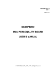
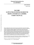
SDIUM/D MAY 1996 MOTOROLA SDI INTERFACE USER’S MANUAL 1996 MOTOROLA INC.; ALL RIGHTS RESERVED Important Notice to Users While every effort has been made to ensure the accuracy of all information in this document, Motorola assumes no liability to any party for any loss or damage caused by errors or omissions or by statements of any kind in this document, its updates, supplements, or special editions, whether such errors are omissions or statements resulting from negligence, accident, or any other cause. Motorola further assumes no liability arising out of the application or use of any information, product, or system described herein; nor any liability for incidental or consequential damages arising from the use of this document. Motorola disclaims all warranties regarding the information contained herein, whether expressed, implied, or statutory, including implied warranties of merchantability or fitness for a particular purpose . Motorola makes no representation that the interconnection of products in the manner described herein will not infringe on existing or future patent rights, nor do the descriptions contained herein imply the granting or license to make, use or sell equipment constructed in accordance with this description. Trademarks Motorola and the Motorola logo are registered trademarks of Motorola Inc.; SDI is a trademark of Motorola Inc. IBM and PC are trademarks of International Business Machines Corporation. Motorola Inc. is an Equal Opportunity/Affirmative Action Employer. The cover illustration shows the standard SDI interface and its low-voltage alternative. SDI HARDWARE INFORMATION SDI HARDWARE INFORMATION This document explains connection and other hardware information for the Motorola SDI Interface. Either this interface or its low-voltage alternative let you use an IBM PC computer (or clone) to manage debugging and other embedded code development with an appropriate target board. SDI interface features are: • Supports the M68MEVB1632 Modular Evaluation Board (MEVB). Also supports a comparable, 5-volt target system that has a background debug mode connector. • Derives +5-volt operating power from the MEVB. Alternatively, derives operating power from a separate +5-volt supply. • Supports a low-voltage (less than 100 milliamp) target system. Alternatively, supports a 5-volt target system. (Low-voltage alternative interface.) • Uses an RS-232 serial connection to the host computer. • Includes a 25-to-9-pin adapter for the communications cable. Paragraph 1 lists interface hardware requirements and specifications. Paragraph 2 explains hookups. Paragraph 3 identifies signals for each pin of the interface connector. )The separate software user’s manual that accompanies your SDI interface explains how to use interface software.) 1 HARDWARE REQUIREMENTS To use the SDI interface, you also need: • An M68MEVB1632 Modular Evaluation Board, comparable development system, or target system that uses the background debug mode connector. (Standard interface.) • A low-voltage development or target system that uses the background debug mode connector. (Low-voltage interface.) • A separate power supply: +5 volts @ 0.25 amps. (Low-voltage interface.) (This separate power supply is optional for the standard interface.) • An IBM PC or compatible computer that has an RS-232 serial port. • A communications cable. One end must have a male DB25 D-shell connector. The other end of the cable must have a female DB9 D-shell connector or a female DB25 D-shell connector. SDIUM/D 3 SDI HARDWARE INFORMATION Table 1 lists interface specifications. Table 1. SDI Interface Specifications Characteristic 2 Specification Operating power + 5 volts @ 0.25 amps Operating temperature 0°C to 40°C Storage temperature 0°C to 85°C Shell dimensions 3.63 x 2.13 x 0.75 inches (92.2 x 54.1 x 19.0 mm) 10-lead ribbon cable dimensions 0.5 inches (12.7 mm) wide, approximately 10 inches (254 mm) long Weight 2.1 ounces (59.54 g) INTERFACE HOOKUPS This paragraph explains the basic hookups for the standard and low-voltage interfaces. Additionally, this paragraph explains how to hook up the standard interface with a separate power supply, and how to hook up the low-voltage interface for a 5-volt target system. 2.1 Standard Interface Hookup Figure 1 shows the standard interface hookup. Use this hookup for an MEVB or for a comparable +5-volt development system. In this hookup, the interface derives its operating power from the communications terminal of the development system. 4 SDIUM/D SDI HARDWARE INFORMATION Figure 1. Standard Interface Hookup Follow these steps for the standard interface hookup: 1. Turn off development-system power. 2. Connect the communications cable to the host computer RS-232 serial port. (Use the 25-to-9-pin adapter, if appropriate.) 3. Connect the communications cable to the interface D-shell connector. 4. Connect the interface 10-pin connector (near the end of the ribbon cable) to the 10-pin background debug mode connector of the MEVB (or comparable development system). (Disregard the 6-pin connector of the ribbon cable.) 5. Turn on development-system power. This completes the hookup; you may begin code development activity per the software user’s manual. Alternative Hookup: You may use a separate (+5 volts @ 0.25 amp) power supply for your standard interface. To do so, install the optional power cable assembly, per the instructions of paragraph 2.3. Then follow the low-voltage hookup instructions (paragraph 2.2), except connect the interface ribbon cable to an MEVB or comparable 5-volt development system. SDIUM/D 5 SDI HARDWARE INFORMATION NOTE If you use the standard interface hookup, but the interface does not work, another person may have used the interface with a separate power supply. If so, you must restore the jumper in header J51, per the conversion instructions of paragraph 2.3. 2.2 Low-Voltage Interface Hookup Figure 2 shows the low-voltage interface hookup. Use this hookup for a low-voltage development system. In this hookup, the interface derives its operating power from a separate power supply (+5 volts @ 0.25 amps). Figure 2. Low-Voltage Interface Hookup Follow these steps for the low-voltage interface hookup: 1. Turn off development-system power. Turn off the separate power supply. 2. Connect the communications cable to the host computer RS-232 serial port. (Use the 25-to-9-pin adapter, if appropriate.) 6 SDIUM/D SDI HARDWARE INFORMATION 3. Connect the communications cable to the interface D-shell connector. 4. Connect the interface 10-pin connector (near the end of the ribbon cable) to the 10-pin background debug mode connector of the development system. (Disregard the 6-pin connector.) 5. The interface power cable assembly has twisted red and black wires. Connect the assembly red wire to the +5-volt terminal of the power supply. Connect the black wire to the ground terminal of the power supply. 6. Turn on development-system power; turn on the power supply. This completes the hookup; you may begin code development activity per the software user’s manual. Alternative Hookup: You may use your low-voltage interface with a +5-volt development system, deriving operating power from the development system’s background debug mode connector. To do so, remove the power cable assembly and install the optional jumper in header J51, per the instructions of paragraph 2.3. Then follow the standard interface hookup instructions (paragraph 2.1). 2.3 Alternative Hookup Conversions For either alternative hookup, you must make a small conversion to your interface. Follow these steps: 1. Make sure that all power is off. Make sure that the interface is disconnected from the development system and is disconnected from the communications cable. 2. Low-voltage interface only: Remove the power connector from the ribbon-cable end of the interface shell. 3. Snap open the interface shell by inserting a screwdriver into a side disassembly slot and twisting slightly. (Figure 3 shows where to insert the screwdriver.) Lift off the shell top half and set it aside. Figure 3. Interface Disassembly Slots SDIUM/D 7 SDI HARDWARE INFORMATION 4. On the bottom side of the printed circuit board (the side with the symbol and the words MADE IN USA), find jumper header J51. 5. If you are converting a standard interface for use with a separate power supply, remove the jumper from header J51. 6. If you are converting a low-voltage interface for use with a 5-volt development system, install a jumper on pins 3 and 4 of header J51. 7. Reposition the printed circuit board in the bottom half of the interface shell. Replace the top half of the shell and snap the shell together firmly. 8. Standard interface only: Insert the optional power connector assembly into the ribbon-cable end of the interface shell, under the cable. 9. This completes the conversion; you are ready for the appropriate alternative hookup. 8 SDIUM/D SDI HARDWARE INFORMATION 3 INTERFACE PIN SIGNALS The SDI interface 10-pin connector has tiny, molded numbers beside each pin. Table 2 explains the signals for each pin. Table 2. SDI Interface Pin Signals Pin Mnemonic Signal 1 DS DATA STROBE – Active-low output signal. During a read cycle, indicates that an external device should place valid data on the data bus. During a write cycle, indicates that valid data is on the data bus. 2 BERR BUS ERROR – Active-low input signal of an invalid bus operation attempt. 3, 5 GND GROUND 4 BKPT / BREAKPOINT – Active-low input signal that signals a hardware breakpoint to the CPU. DSCLK Development Serial Clock – Clock input signal for the background debug mode. 6 FREEZE FREEZE – Active high signal that the CPU has acknowledged a breakpoint. 7 RESET RESET – Active-low, bi-directional signal to start a system reset. 8 DSI DEVELOPMENT SERIAL IN – Serial data input signal for background debug mode. Signal is also: INSTRUCTION PIPE 1 for CPU16-based MCUs. INSTRUCTION FETCH for CPU32-based MCUs. 9 VDD (or Vbias) 10 DSO VOLTAGE DRAIN – DRAIN – Interface operating power (not used for low-voltage or separate-power hookups). DEVELOPMENT SERIAL OUT – Serial data output signal for background debug mode. Signal is also: INSTRUCTION PIPE 0 for CPU16-based MCUs. INSTRUCTION PIPE for CPU32-based MCUs. SDIUM/D 9 SDI HARDWARE INFORMATION 10 SDIUM/D