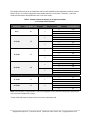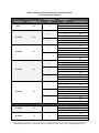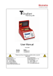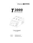
1
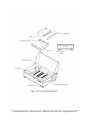
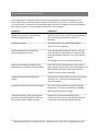
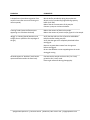
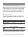
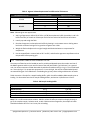
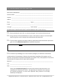
OPERATING MANUAL Horizon® 11.14 #11068020 Horizon® 20.25 #21069026 Horizontal Electrophoresis Apparatus H11.14 Shown Apogee Electrophoresis | 101 Kane Street | Baltimore, MD 21224 USA | apogeephoresis.com Apogee Electrophoresis | 101 Kane Street | Baltimore, MD 21224 USA | apogeephoresis.com HORIZONTAL APPARATUS OPERATING MANUAL - TABLE OF CONTENTS Before You Begin 1.0 Important Information 1.1 Safety Warnings 1.2 Components 1.3 Operating Instructions Gel Casting 2.0 2.1 Assembly for Gel Casting 2.1.1 Gel Casting Procedure 2.1.2 Electrophoresis Post-Electrophoresis 2.2 2.2.1 Troubleshooting Guide 3.0 Applications 4.0 Considerations for Agarose Gel Electrophoresis 4.1 Selecting Gel Concentration 4.1.1 Preparing Agarose for Gels 4.1.2 Preparing Samples and Loading the Gel 4.1.3 Using Multiple Combs 4.1.4 Considerations for Electrophoresis Buffers 4.2 Resolution Effects 4.2.1 Heat Effects 4.2.2 Ethidium Bromide Staining of Double-Stranded DNA 4.3 Gel Photography 4.4 Related Products 5.0 H11.14 Accessories and Replacement Parts 5.1 H20.25 Accessories and Replacement Parts 5.2 Care and Handling 6.0 Materials and Care 6.1 General Specifications 6.2 Technical Support and Service 6.3 Instructions for Return Shipment 6.4 Apogee Electrophoresis | 101 Kane Street | Baltimore, MD 21224 USA | apogeephoresis.com Cleaning and Decontamination for Return Shipment 6.4.1 Notice Regarding the Return of Apparatus Products 6.4.2 Warranty 7.0 Warranty 7.1 Declaration of Conformity and CE Mark 7.2 Decontamination Declaration 8.0 FIGURES 1. Horizon 11.14, 20.25 Apparatus Components 2. Horizon 11.14, 20.25 Gel Casting Configuration TABLES 1. 2. 3. 4. 5. 6. 7. 10X TAE Electrophoresis Buffer 10X TBE Electrophoresis Buffer Agarose Volume Requirement for Different Gel Thicknesses 10X Sample Loading Buffer Sample Volumes for Horizon 11.14 Apparatus Combs as a Function of Gel Thickness Sample Volumes for Horizon 20.25 Apparatus Combs as a Function of Gel Thickness Nominal Electrophoresis Times for 1% Agarose Gels at Various Voltages HORIZON® is a registered trademark of Apogee Designs, Ltd. DELRIN® is a registered trademark of E.I. duPont de Nemours & Co. Tygon® is a registered trademark of Norton Company. Apogee Electrophoresis | 101 Kane Street | Baltimore, MD 21224 USA | apogeephoresis.com 1.0 BEFORE YOU BEGIN 1.1 IMPORTANT INFORMATION Horizon® H11.14 and H20.25 electrophoresis units are authorized for laboratory research use only. They have not been qualified for use in any human or animal diagnostic or therapeutic application. Use for other than the intended use may be a violation of applicable law. The H11.14 and H20.25 Horizontal Gel Electrophoresis Apparatus are designed for separation of preparative and analytical quantities of nucleic acids. They are suitable for agarose gel electrophoresis procedures. Because of the double-wall construction of the H11.14 and H20.25 Apparatus, the heat generated by electrophoresis does not dissipate as quickly as with Models H4 and H5. With the Horizon Apparatus, gels electrophoresed at the same voltage will be warmer, and samples will move faster. These effects are particularly evident at higher voltages, and may necessitate buffer cooling steps to avoid melting the gel. Consult Chapter 4, Table 7, for further information. If the product is used in a manner not specified by Apogee, the protection provided by safety features of the product may be impaired. Please carefully follow the manual’s instructions. Do not alter equipment or operate with broken components. Failure to adhere to these directions could result in personal and/or laboratory hazards as well as invalidate the equipment warranty. 1.2 SAFETY WARNINGS CAUTION: SHOCK HAZARD Although equipped with a safety interlock system, this apparatus should always be operated with extreme caution. Careless handling could result in electrical shock. The power supply should have open-circuit sensing. This apparatus should always be operated with caution. Careless handling can result in electrical shock. The system should be operated by trained personnel only. Some reagents indicated for use in this manual may be hazardous (e.g., ethidium bromide, acetic acid, and boric acid, etc.); exercise care with these reagents. Always follow the power supply manufacturer’s recommendations for use and follow safety procedures. Always turn off the DC power source before disconnecting the power cords from the apparatus. Never operate damaged or leaking equipment. Inspect the apparatus, electrical connections and power cords prior to use. For maximum safety, always operate this apparatus in an area that is not accessible to unauthorized personnel. Apogee Electrophoresis | 101 Kane Street | Baltimore, MD 21224 USA | apogeephoresis.com 1.3 COMPONENTS The H11.14 and H20.25 Apparatus are designed for simplified gel casting and electrophoresis. These apparatus are engineered for durable performance and easy storage. Refer to Figures 1 and 2 to identify the following features and components: One ABS electrophoresis tank with clear acrylic safety interlock lid, adjustable leveling feet, selfsealing ports for buffer circulation, molded V-grooves for placement of gel casting dams, and a tray support platform with red well- visualization strips and black centimeter graduations One UVT tray (11 14 cm or 20 25 cm gel bed) with multiple positioning slots for well-forming combs One pair of aluminum gel casting dams One precision machined Delrin® well-forming comb: o with H11.14 Apparatus: one 14 tooth, 1 mm-thick o with H20.25 Apparatus: one 20 tooth, 1 mm-thick One pair of tubing barb adapters for use with 6 mm (0.25-in) I.D. recirculation tubing One pair of pipe plugs to seal the buffer circulation ports if recirculation is not used One bull’s eye level One pair of 122 cm, Red & Black power cords One instruction manual Many of these components are also available separately. This chapter provides operating instructions for the H11.14 and H20.25 Apparatus. Refer to Chapter 4 for information on commonly used buffers, agarose concentrations, sample volumes, and postelectrophoresis handling of the gel. Review Figure 1 to identify the features and components discussed in these instructions. Apogee Electrophoresis | 101 Kane Street | Baltimore, MD 21224 USA | apogeephoresis.com Apogee Electrophoresis | 101 Kane Street | Baltimore, MD 21224 USA | apogeephoresis.com 2.0 OPERATING INSTRUCTIONS 2.1 GEL CASTING Note: If you are using gels cast in advance with the Horizon 11.14 or 20.25 Gel Casting System, proceed to Section 2.2. 2.1.1 ASSEMBLY FOR GEL CASTING 1. Place the apparatus on a flat, level surface. Open the safety interlock lid. Place the UVT tray in the electrophoresis tank on the tray support platform. The red well-visualization strips should be visible through the tray. 2. Slide the gel casting dams simultaneously into the V-grooves in the electrophoresis tank. Make sure that the tops of the dams are level. Apply even, gentle downward pressure to both dams to seat the sealing surfaces of the dams against the ends of the UVT tray. Do not force the dams down since this can displace the tray out of level. 3. Place the bull’s-eye level in the center of the UVT tray and turn the adjustable feet, as needed, to level the apparatus. 4. Insert a comb or combs into the preferred alignment slots of the UVT tray. The teeth of each comb should line up over one of the well-visualization strips. Ensure that each comb rests unobstructed and squarely in its slots. The apparatus is now ready for gel casting (figure 3). Note: Nucleic acids will migrate toward the positive (red) electrodes at the right side of the Horizon Apparatus. 2.1.2 GEL CASTING PROCEDURE 1. Prepare the desired volume of molten agarose in electrophoresis buffer in a bottle or Erlenmeyer flask. For information on agarose preparation, buffer formulation, and the effects of varying gel concentration and volume, see Chapter 5. 2. Loosely cap the container. Allow the molten agarose to cool to 50°C to 60°C. Caution: Casting gels with agarose above 60°C will result in poor sealing at the gel casting dams and may cause the bottom of the UVT tray to bow. 3. Pour the measured volume of molten agarose into the center of the UVT tray. Use a pipette tip to distribute the agarose evenly over the surface of the UVT tray and to remove any air bubbles, particularly from around comb teeth. Note: If molten agarose leaks from below gel casting dams, be sure dams are seated properly (see Section 3.1). 4. Allow the agarose to cool until thoroughly solidified, usually 15 to 30 min. 5. To store gels prior to electrophoresis, gently remove gel casting dams and comb(s), wet the gel surface with a small amount of electrophoresis buffer and wrap the UVT tray (with the gel still in Apogee Electrophoresis | 101 Kane Street | Baltimore, MD 21224 USA | apogeephoresis.com place) with plastic wrap or seal in a plastic bag. Store at 4°C. Gels can be stored for 1 to 2 days or longer, if well sealed. 2.2 ELECTROPHORESIS 1. Remove the gel casting dams, rinse them with deionized water and wipe them dry before storing. 2. When transferring a gel from the Horizon 11.14 or 20.25 Gel Casting System, verify that the UVT tray is oriented so that the sample wells are in the desired alignment. Check that the sample wells line up over one of the well-visualization strips and that the UVT tray is seated flush on the tray support platform. Note: Nucleic acids will migrate toward the positive (red) electrodes at the right side of the apparatus. 3. Pour sufficient electrophoresis buffer into the electrophoresis tank to cover the gel to a depth of 1 to 2 mm. This requires ~700 ml for the H11.14 Apparatus and ~1.55 L for the H20.25 Apparatus. Apogee Electrophoresis | 101 Kane Street | Baltimore, MD 21224 USA | apogeephoresis.com 4. To use the buffer circulation system (especially important when using TAE electrophoresis buffer – see Chapter 4), use the supplied tubing barb adapters to connect 6 mm (0.25-in) I.D. tubing to the fittings on the rear of the H11.14 or H20.25. Connect a circulation pump to the tubing and set for low speed. 5. Gently remove the comb(s). To avoid tearing the bottom of the wells, gently wiggle each comb to free the teeth from the gel. Slightly lift up one side of the comb, then the other. Rinse each comb with deionized water and wipe dry before storing. 6. Remove any trapped air bubbles to ensure that the wells fill completely with buffer. 7. Use a micro-pipet or automatic pipet to load the samples on the floor of the wells. Samples should contain sufficient glycerol or sucrose to be denser than the electrophoresis buffer. For sample loading buffer formulation and the loading capacities for each comb relative to various gel thicknesses, see Tables 5 and 6 in Chapter 4. 8. Close the safety interlock lid. 9. Connect the power cords to the electrophoresis tank and a 250 VDC power supply. Connect the positive (red) lead at the right side of the apparatus and the negative (black) lead at the left. 10. If you are using the buffer circulation feature, start the pump. 11. Turn on the power supply and select the desired voltage. Small bubbles will rise from the electrodes when the unit is properly connected. Nominal electrophoresis times for TAE and TBE buffers are listed in Table 7 in Chapter 4. 12. Monitor electrophoresis by following the migration of the bromophenol blue (BPB) dye. Movement should be in the direction of the positive electrodes at the right side of the apparatus. Use the black 1 cm graduations visible below the UVT tray to determine approximate migration rates. 13. When electrophoresis is complete, turn off the power supply. Disconnect the power cords from the power supply and the apparatus. Turn off the circulation pump. 2.2.1 POST-ELECTROPHORESIS 1. Open the safety interlock lid. Lift out the UVT tray and gel. 2. Slide the gel out of the UVT tray for staining or subsequent analysis for further information. Remove the gel with care; agarose gels tear easily if not properly supported. 3. Properly discard the electrophoresis buffer. Use the pouring spouts at the front corners of the unit to transfer the buffer to a waste receptacle. Do not reuse the buffer. Disconnect the buffer circulation pump by pressing the metal tab on each buffer port to release the quick-connect fittings. 4. Thoroughly rinse the electrophoresis tank, quick-connect fittings, and tubing with deionized water. 5. Remove any residual agarose from the UVT tray by rinsing with deionized water. Wipe dry or allow to air dry before storing. Apogee Electrophoresis | 101 Kane Street | Baltimore, MD 21224 USA | apogeephoresis.com 3.0 TROUBLESHOOTING GUIDE Some suggestions for resolving common problems are given below. Should these suggestions not resolve the problem, please call Technical Support (see Section 6.3 for numbers). If the unit must be returned for repair, also contact our service department, the technical support or your local distributor for shipping instructions. Please include a full description of the problem. PROBLEM COMMENTS Bubbles do not appear on the electrodes when DC voltage is connected. Verify that the DC power supply is operating properly. Verify continuity of the power cords with an ohmmeter. Electrodes turn gray. This occurs under normal operating conditions. Performance is not affected. Agarose solution leaks during casting. the gel casting dams are clean. Verify that the sealing surfaces of the UVT tray and Verify that the gel casting dams are properly seated. Verify that the ends of the UVT tray are flat and free of nicks. Cool the agarose to 50°C to 60°C before pouring. BPB dye turns yellow (pH change) during electrophoresis. Results are uninterpretable. Check the pH of the electrophoresis buffer (refer to tables 1 and 2). Be sure to use Tris Base and not Tris-HCl. Mix the buffer periodically during electrophoresis. Connect a pump to circulate the buffer. Samples leak underneath the gel upon loading. The bottom of the wells were torn when the comb was removed. See 2.2, #5 for recommended comb removal procedure. Gel melts or becomes soft near sample wells. This is due to the combination of pH drift and high temperature. Circulate or remix buffer periodically. Reduce the electrophoretic voltage. Pronounced ‘smiling’ along one edge of the gel occurs (corresponding bands in different lanes migrate slower toward one edge). Gel was cast or electrophoresed out of level. Use the ‘bull’s eye’ level to verify that the apparatus is level prior to gel casting and electrophoresis. Apogee Electrophoresis | 101 Kane Street | Baltimore, MD 21224 USA | apogeephoresis.com PROBLEM COMMENTS S-shaped lanes (anomalous migration-front results in lanes that are not all running at a uniform speed). Mix the buffer periodically during electrophoresis. Switch to a low conductivity/high buffering capacity buffer (0.5X TBE). Reduce the salt concentration of the sample. Connect a pump to circulate the buffer. ‘Flaming’ bands (excessive fluorescence appearing as a trail above the band) Reduce the amount of DNA in the sample. Reduce the amount of protein and/or glycerol in the sample. ‘Wiggly’ or ‘slanting’ bands (bands are not straight lines or parallel to the top edges of the gel). Verify that the wells are free of particles and bubbles before and after loading samples. Verify that the agarose is completely dissolved before casting gels. Remove any particulate matter from the agarose before casting gels. Be sure that bubbles are not trapped against the comb during gel casting. All bands appear as ‘doublets’ (each band is represented twice within the same lane). Concentrate the sample and use a thin (2 to 3 mm) gel with a thin (1 mm) comb. Prevent gel movement during photography. Apogee Electrophoresis | 101 Kane Street | Baltimore, MD 21224 USA | apogeephoresis.com 4.0 APPLICATIONS 4.1 CONSIDERATIONS FOR AGAROSE GEL ELECTROPHORESIS 4.1.1 SELECTING GEL CONCENTRATION The choice of agarose concentration for a gel depends on the range of fragment sizes to be separated. The typical agarose concentration is 0.3% to 2.0%. Large DNA fragments require low-percentage gels, while small DNA fragments resolve best on high-percentage gels. Gels containing <0.5% agarose are very weak and should be electrophoresed at a low temperature (~4°C). For routine electrophoresis, 0.75% to 1.0% agarose gels provide a wide range of separation (0.15 to 15 kb). For a more complete treatment of factors that affect the separation of nucleic acids in agarose gels, see Section 4.2. Thin (2 to 3 mm thick) and low-percentage agarose gels yield better photographs than thick or high-percentage gels, which exhibit increased opaqueness and auto-fluorescence. 4.1.2 PREPARING AGAROSE FOR GELS The following protocol yields a 1% (w/v) agarose gel. Varying the amount of agarose added in step 1 will produce gels of higher or lower concentration. See Section 4.2 to determine whether Tris-acetate/EDTA (TAE) buffer or Tris-borate/EDTA (TBE) buffer (formulas in tables 1 and 2) is preferable for your specific application. To determine the volume of agarose solution required to produce gels of various thicknesses, see table 3. Table 1. 10X TAE Electrophoresis Buffer Component Tris base Na2EDTA•2H2O Sodium acetate, anhydrous Glacial acetic acid Deionized water Amount 48.4 g 7.4 g 16.4 g 17.0 ml to 1 L Concentration 400 mM 20 mM 200 mM 296 mM ----- Note: This is a 10X concentration solution. Dilute with deionized water prior to use. Final pH should be 7.8 at 25°C. Table 2. 10X TBE Electrophoresis Buffer Component Tris base Boric acid, anhydrous Na2EDTA•2H2O Deionized water Amount 121.1 g 55.6 g 3.7 g to 1 L Concentration 1M 0.9 M 10 mM ----- Note: This is a 10X concentration solution. Dilute with deionized water prior to use. Final pH should be 8.3 at 25°C. Apogee Electrophoresis | 101 Kane Street | Baltimore, MD 21224 USA | apogeephoresis.com Table 3. Agarose Volume Requirement for Different Gel Thicknesses Gel Dimensions (cm) Gel Thickness (mm) 3 4 5 3 4 5 11 x 14 20 x 25 Agarose Volume (ml) 50 65 80 150 200 250 Note: Volumes given are approximate. 1. Add 1 g of agarose per 100 ml of 1X TAE or 1X TBE electrophoresis buffer (see tables 1 and 2 for buffer formulas) in a bottle or Erlenmeyer flask of at least twice the final volume of solution. 2. Loosely cap and weigh the flask. 3. Dissolve the agarose in electrophoresis buffer by heating in a microwave oven or boiling water bath with occasional mixing until no granules of agarose are visible. 4. Weigh the flask and adjust to the original weight with deionized water to compensate for evaporation. 5. Put the capped flask in a water bath at 50°C to 60°C, and allow the agarose to equilibrate at that temperature before pouring gels. 4.1.3 PREPARING SAMPLES AND LOADING THE GEL The amount of DNA that can be loaded per well is variable and depends upon the number and size of the DNA fragments and the cross-sectional area of the well (well width gel thickness). As a general rule, the minimum amount of DNA detectable by ethidium bromide staining is 1 ng in a 5 mm wide band on a 3 mm thick gel. For preparative purposes on a 3 mm thick gel, the amount of DNA loaded should not exceed 50 ng per 5 mm wide band. Overloading the gel may cause trailing and distortion of bands. Table 4 contains a formula for a sample loading buffer, which should be added to DNA samples prior to loading. For alternative formulas for sample loading buffers, see Section 4.4, References 1 and 2. Table 4. 10X Sample Loading Buffer Component Glycerol Na2EDTA•2H2O Sodium dodecyl sulfate Bromophenol blue Deionized water Amount 5 ml 0.37 g 0.1 g 0.01 g to 10 ml Concentration 50% (v/v) 100 mM 1% (w/v) 0.1% (w/v) ------ Note: This is a 10X concentration solution. Add 0.1 volume of buffer to samples and apply directly to gel. If the samples contain l-cohesive ends, as with l DNA restriction fragments, the samples in buffer should be heated at 65°C for 5 to 10 min prior to loading. Apogee Electrophoresis | 101 Kane Street | Baltimore, MD 21224 USA | apogeephoresis.com The sample volumes that can be loaded per well for each standard Horizon Apparatus comb are listed in tables 5 and 6. For analytical purposes, keep sample volumes to a minimum. Generally, 1 mm thick combs provide sharper band definition than 2 mm thick combs. Table 5. Sample Volumes for Horizon 11.14 Apparatus Combs as a Function of Gel Thickness Comb Type Tooth Width (mm) Comb Thickness (mm) Prep* 92 2 1 10 Tooth 7.9 2 1 14 Tooth 4.7 2 1 20 Tooth 3.8 2 Gel Thickness (mm) 3 4 5 3 4 5 3 4 5 3 4 5 3 4 5 3 4 5 3 4 5 Capacity/Well (ul) 410 600 780 17 25 33 34 50 66 10 15 20 20 30 40 8 12 16 16 24 32 3 4 5 3 4 5 15 23 30 11 17 22 Multichannel Pipet Combs 12 Tooth 7.2 1 24 Tooth 2.7 2 Note: Volumes given are approximate. Low-percentage gels (<0.6%) and low-melting-point agarose gels may have lower sample well volumes. *Tooth width and capacity values are for the central, preparative well. Apogee Electrophoresis | 101 Kane Street | Baltimore, MD 21224 USA | apogeephoresis.com Table 6. Sample Volumes for Horizon 20.25 Apparatus Combs as a Function of Gel Thickness Comb Type Tooth Width (mm) Comb Thickness (mm) Prep* 165 2 1 12 Tooth 12.7 2 1 15 Tooth 9.5 2 1 20 Tooth 6.4 2 3 1 30 Tooth 4.7 2 3 Gel Thickness (mm) 3 4 5 3 4 5 3 4 5 3 4 5 3 4 5 3 4 5 3 4 5 3 4 5 3 4 5 3 4 5 3 4 5 Capacity/Well (ul) 1,100 1,600 2,100 28 41 54 57 82 108 21 31 40 42 62 80 14 21 27 28 42 54 42 63 81 10 15 20 21 30 40 31 45 60 3 4 5 3 4 5 15 23 30 11 17 22 Multichannel Pipette Combs 21 Tooth 7.2 1 42 Tooth 2.7 2 Apogee Electrophoresis | 101 Kane Street | Baltimore, MD 21224 USA | apogeephoresis.com Note: Volumes given are approximate. Low-percentage gels (<0.6%) and low-melting-point agarose gels may have lower sample well volumes. *Tooth width and capacity values are for the central, preparative well. 4.1.4 USING MULTIPLE COMBS The multiple comb alignment slots in the Horizon 11.14 and 20.25 Apparatus lend themselves to a variety of applications. For example, using two rows of wells on the same gel doubles the number of samples of ‘mini-prep’ plasmid DNA that can be screened. A row of wells at the bottom of the gel provides a convenient way to include quantitative standards on a gel for Southern blot hybridization. Note: To use this feature, add the standards to the bottom row and let them migrate into the gel for just a few minutes before electrophoresis is complete. 4.2 CONSIDERATIONS FOR ELECTROPHORESIS BUFFERS 4.2.1 RESOLUTION EFFECTS For electrophoresis of agarose gels of the same concentration and at a fixed voltage, TAE buffer provides better resolution of fragments >4 kb in length, while TBE buffer offers better resolution of 0.1 to 3 kb fragments. TBE has a higher buffering capacity and lower conductivity than TAE and is therefore better suited for high voltage (>150 V) electrophoresis. TBE buffer also generates less heat at an equivalent voltage and does not allow a significant pH drift. Note: Because of its lower buffering capacity, TAE requires circulation or mixing periodically for fulllength electrophoresis, particularly at higher voltages. Band compression of fragments of high molecular weight (>5 kb) occurs as voltage increases. This effect is observed with both TBE and TAE buffers. Band definition remains sharp, even above 200 V, provided that the gel is not over-loaded. Linear DNA fragments from 0.15 to 10 kb (25 ng total) are easily resolved on a 0.8% agarose gel in 0.5X TBE buffer electrophoresed for 30 min at 200 V. TAE buffer provides better results for analysis of supercoiled DNA. Anomalous migration of supercoiled DNA, particularly with high molecular weight (>7 kb) fragments, occurs when TBE buffer is used at >75 V. Use of TBE buffer also reduces the ability to resolve supercoiled DNA from nicked circular and linear DNA in the absence of ethidium bromide. For accurate size determination with supercoiled DNA, supercoiled DNA of known sizes must be electrophoresed in an adjacent lane of the gel. 4.2.2 HEAT EFFECTS Electrophoresis at high voltages generates heat, and high conductivity buffers such as TAE generate more heat than low conductivity buffers. Caution should be exercised in agarose gel electrophoresis at >175 V. Heat buildup can cause gel artifacts such as S-shaped migration fronts, and in prolonged electrophoresis, can melt the agarose gel. Low-melting-point agarose gels should never be electrophoresed at high voltages. Nominal electrophoresis times for agarose gels in TBE and TAE buffers at various voltages are listed in table 7. Apogee Electrophoresis | 101 Kane Street | Baltimore, MD 21224 USA | apogeephoresis.com Note: Electrophoretic procedures originally developed with Models H4 and H5 often generate additional heat when performed with Horizon Apparatus. At higher voltages, these heat effects can melt the agarose gel. Additional buffer circulation and cooling steps may be necessary to adapt such procedures for use with Horizon Apparatus. To prevent drying of the gel and ensure an even voltage gradient across the gel bed, submerge the gel with electrophoresis buffer to a depth of only 1 to 2 mm. Submerging the gel at a depth >2 mm is unnecessary and increases electrical current and heat. Table 7. Nominal Electrophoresis Times for 1% Agarose Gels at Various Voltages Electrophoresis voltage (V) 25 50 100 150 250 Buffer TBE TAE 0.5X TBE TBE TAE TBE TAE 0.5X TBE TBE TAE TBE TAE 0.5X TBE Time in Hours for the 11.14 18 30 17 7.4 7.0 3.4 2.7 3.6 2.0 1.4 0.9 ND 1.1 Time in Hours for the 20.25 60 76 50 26 29 11 12 11 7.2 4.4 3.0 ND 2.8 Note: Values were determined with the gel submerged 1.5 mm; the operating current ranged from 4 to 360 mA. Current and electrophoresis time vary with buffer volume, gel thickness, and applied voltage. Formulations for TAE and TBE electrophoresis buffers are listed in tables 1 and 2. Values represent the time required for BPB dye to migrate 13 cm from the origin in the H11.14 and 22 cm in the H20.25. In a 1% agarose gel, BPB comigrates with DNA fragments of approximately 200 bp in 1X TBE buffer and 400 bp in 1X TAE buffer. 4.3 ETHIDIUM BROMIDE STAINING OF DOUBLE-STRANDED DNA To visualize double-stranded DNA after electrophoresis, the gel should be transferred from the UVT tray to a 0.5 µg/ml solution of ethidium bromide in deionized water. Approximate staining time is 10 to 15 min for a 3 mm thick gel and longer for thicker gels. As an optional subsequent step to reduce background fluorescence, the gel can be destained in deionized water for 15 to 30 min. Alternatively, ethidium bromide may be added directly to the agarose prior to casting, so that the gel is electrophoresed in the presence of ethidium bromide. However, this procedure reduces the migration rate and may alter the relative electrophoretic mobility of nucleic acids (reference 3). Apogee Electrophoresis | 101 Kane Street | Baltimore, MD 21224 USA | apogeephoresis.com 4.4 GEL PHOTOGRAPHY A darkroom or light-tight enclosure, camera, digital camera and UV light source are required for photography of gels stained with ethidium bromide. For best results, place the stained gel directly on top of a 300 nm or 254 nm transilluminator. If the camera contains ASA 3000 or equivalent film the required exposure at maximum aperture (f/4.5) should be between 1/4 and 2 seconds. The intensity of the light source, distance between the gel and the camera lens, film or shutter speed, lens aperture, and choice of photographic filters will all affect the exposure time. Use of a 300 nm transilluminator allows gels to be photographed while in place in the UVT tray, although this will increase the required exposure time. Transmitted UV light yields the highest sensitivities (1 ng of DNA in a 5 mm wide band) in photographing gels. Photography under incident UV light is approximately 10 times less sensitive. A UV-blocking filter (Kodak 2B Wratten filter) used in conjunction with a red gelatin filter (Kodak 23A Wratten filter) provides the highest contrast. Due to the fluorescence of the 2B filter, the two filters must be oriented so that the red 23A filter is adjacent to the camera lens. The ethidium bromide-DNA complex fluoresces at 590 nm upon excitation at 302 nm (2). Short-wave (254 nm) sources provide an equivalent level of sensitivity; however, high-energy UV causes photodimerization and nicking of the DNA. Long-wave transilluminators (366 nm) are much less efficient. REFERENCES 1. Maniatis, T., Fritsch, E.F., and Sambrook, J. (1982) Molecular Cloning: A Laboratory Manual, Cold Spring Harbor Laboratory, Cold Spring Harbor, New York. 2. Rickwood, D. and Hames, B.D. (eds.) (1982) Gel Electrophoresis of Nucleic Acids: A Practical Approach, IRL Press, Oxford, England. 3. Longo, M.C. and Hartley, J.L. (1986) LTI FOCUS® 8:3. Apogee Electrophoresis | 101 Kane Street | Baltimore, MD 21224 USA | apogeephoresis.com 5.0 RELATED PRODUCTS AND REPLACEMENT PARTS 5.1 H11.14 ACCESSORIES DESCRIPTION CATALOG # 10 well precision machined white Delrin comb 1.0 mm thick 2.0 mm thick 11956026 11956059 14 well precision machined white Delrin comb 1.0 mm thick 2.0 mm thick 11956042 11956075 20 well precision machined white Delrin comb 1.0 mm thick 2.0 mm thick 21076013 21076021 Horizon 11.14 Gel Casting Apparatus (Base, UVT tray, 2 casting dams) System 11068046 H11.14 UVT Tray Each 11084019 H11.14 Aluminum Casting Dams Package of 2 11068053 Power Cord Replacements 1 black & 1 red, 122 cm long Package of 2 11099025 H11.14 Pt/Nb Electrode Replacement Includes all necessary components Kit 11958061 5.2 H20.25 ACCESSORIES DESCRIPTION CATALOG # 12 well precision machined white Delrin comb 1.0 mm thick 2.0 mm thick 11953064 11953080 15 well precision machined white Delrin comb 1.0 mm thick 2.0 mm thick 11953072 11953098 20 well precision machined white Delrin comb 1.0 mm thick 2.0 mm thick 3.0 mm thick 41007014 41007022 41007030 30 well precision machined white Delrin comb 1.0 mm thick 2.0 mm thick 3.0 mm thick 11951043 11951019 11951050 H20.25 Gel Casting Apparatus (Base, UVT tray, 2 casting dams) System 21069067 H20.25 UVT Tray Each 31006026 H20.25 Aluminum Casting Dams Package of 2 21069059 Power Cord Replacements 1 black & 1 red, 122 cm long H20.25 Pt/Nb Electrode Replacement Package of 2 Kit 11099025 21069042 Apogee Electrophoresis | 101 Kane Street | Baltimore, MD 21224 USA | apogeephoresis.com Includes all necessary components 6.0 CARE AND HANDLING 6.1 MATERIALS AND CARE Each H11.14 and H20.25 apparatus is fabricated from high quality ABS and acrylic plastic. Acrylic and ABS both have very good heat, impact, and chemical resistance but will not withstand autoclaving. Caution: Both electrodes are made from Pt/Nb strip for durability. Use care when cleaning this apparatus to prevent breakage of the electrodes because they are not warranted against breakage. All components may be washed with water and a detergent. To remove grease and oils, use a hexane, kerosene, or aliphatic naphtha. Never use abrasive cleaners, window sprays, or any fluid that may contain toluene, methylene chloride, phenol, acetone, benzene, halogenated hydrocarbon solvents, or undiluted laboratory alcohols. Routine inspection and maintenance will ensure both the safety and the performance of your horizontal gel apparatus. For replacement parts, call your distributor or Apogee Technical Support. Because of the relatively high voltages that may be used, inspect electrical connections and power cords often. If power cords show any signs of wear or damage (e.g., cracks, nicks, abrasions, melted insulation or bare wire), replace immediately. Examine the electrode banana plugs and connection nuts to ensure that they are free of corrosion or they may offer higher resistance thus heating up and risking sparks and fire. 6.2 GENERAL SPECIFICATIONS Type Dimensions (W × L x H) Gel Dimensions Maximum gel thickness Voltage Range Current Range Electrode material Operating Temperature Range Construction H11.14 21.5 x 31.5 10.5 cm 11 x 14 cm 10 mm 250 VDC Max 4 – 360 mA, 0.5 Max Pt/Nb strip 4-30°C ABS, acrylic, aluminum H20.25 32.0 x 42.5 12.0 cm 20 x 25 cm 10 mm 250 VDC Max 4 – 360 mA, 0.5 Max Pt/Nb strip 4-30°C ABS, acrylic, aluminum Apogee Electrophoresis | 101 Kane Street | Baltimore, MD 21224 USA | apogeephoresis.com 6.3 TECHNICAL SUPPORT AND SERVICE Should you have any problems with this unit, please contact: Apogee Designs, Ltd. Attn: Electrophoresis Support 101 Kane Street Baltimore, MD 21224 USA Phone: Fax: Email: 443.744.0368 9 to 5PM EST, Monday through Friday 410.633.3666 [email protected] 6.4 INSTRUCTIONS FOR RETURN SHIPMENT IMPORTANT: Before sending the unit back to us, it is absolutely necessary to call our Technical Support department to get authorization to return products! Return only defective devices. For technical problems which are not definitively recognizable as device faults please contact Apogee Technical Support. Use the original box or a similarly sturdy one. Label the outside of the box with CAUTION! SENSITIVE INSTRUMENT! Please enclose a detailed description of the fault and when, or how, the problem occurred. Important: Clean all parts of the instrument from residues and of biologically dangerous, chemical and radioactive contaminants. Please include a written confirmation (use the respective Decontamination Declaration/Certificate following in Section 8 that the device is free of biologically dangerous and radioactive contaminants in each shipment. If the device is contaminated, it is possible that Apogee will be forced to refuse to accept the device. The sender of the repair order will be held liable for possible damages resulting from insufficient decontamination of the device. Please enclose a note which contains the following: 1. Sender's name and address and, 2. Name of a contact person for further inquiries with telephone number. 6.4.1 CLEANING AND DECONTAMINATION FOR RETURN OF PRODUCTS Use the original product packaging whenever possible, to avoid damage to the unit being returned. All returned material must be cleaned and decontaminated prior to shipping. The components of apparatus products are fabricated from a variety of materials including: ABS, acrylic, vinyl, glass, silicone, aluminum and stainless steel. Please clean any unit or product to be returned using the following three step procedure. Apogee Electrophoresis | 101 Kane Street | Baltimore, MD 21224 USA | apogeephoresis.com STEP 1: GENERAL CLEANING PROCEDURE For materials not contaminated with biological or radiological substances, components may be gently washed with water and a non-abrasive detergent, and rinsed with deionized water. Dry using a soft cloth, paper towel or allow to air dry. A light application of hexane, kerosene, or aliphatic naphtha will remove grease. To prevent surface damage, never use abrasive cleaners, window sprays or scouring pads to clean these products. Avoid excessive exposure to UV light, phenol, acetone, benzene, halogenated hydrocarbon solvents, or undiluted alcohols because they may cause crazing. STEP 2: BIOLOGICAL CLEANING PROCEDURE Using a solution of either 5% household bleach in water or 70% ethanol in water, wipe down the apparatus using a clean cloth or sponge. Neutralize the solution by wiping the surface with a mild, nonabrasive detergent and rinse well with water. STEP 3: RADIOLOGICAL DECONTAMINATION PROCEDURE To meet various regulatory and safety standards, please follow the decontamination procedure given here if radioactive materials are used with this product or are used in the vicinity of where this apparatus has been used or stored. WARNING: We cannot and will not accept return of products that are contaminated with any radioactivity. For beta emitting isotopes such as 32P, use a GM-type radioactivity meter calibrated in counts per minute (CPM) to determine the background readings for your work area. Wearing latex gloves, survey the unit to be returned with the GM meter. If any part of the unit is found to show readings higher than background, wash the area using Radiacwash© (Atomic Products Corp.) and paper towels, or another similar commercially available detergent. If none are available, a mild detergent or a Formula 409© like solution will do. As you clean, discard liquid and solid waste (gloves and paper towels) according to your local and institutional regulations for radioactive material disposal. Continue washing until the GMmeter reading for the contaminated area(s) is equal to or below background. To decontaminate units where a GM-meter is not as useful for detection, as with 'H, or "S, it will be necessary to perform swipes of the unit and detect using a scintillation counter. The unit should be dry. Wipe surfaces with dry paper circles (these are commercially available or you can make your own). Areas can be charted, so that individual swipes can be done on different surfaces to better isolate areas of contamination. Swipes should be placed into individual scintillation vials with an appropriate floor and then analyzed on a properly programmed scintillation counter. If contamination above 100 disintegrations per minute dpm/100cm2 (dpm=CPM/efficiency) is found, wash the area as described above in 32P decontamination. After cleaning the area, swipe it a second time to determine the amount of contamination remaining. If the area still has greater than 100 dpm/cm2, continue the cycle of swipes and washing until you achieve a reading of less than 100 dpm/cm2. Apogee Electrophoresis | 101 Kane Street | Baltimore, MD 21224 USA | apogeephoresis.com Once the unit has been determined to be radiation free (<100dpm/cm2) remove all the hazardous and radioactive labels from the unit. If the labels cannot be removed, deface them. Failure to do so may result in a significant delay or refusal of repair. If your unit has non removable contamination (detectable with a GM-meter and not with paper swipes, or detectable with paper swipes but after continued washing the dpm/cm2 remains constant and above 100) of a short half life isotope such as 32P, it may be stored for ten half lives of isotopic decay and the decontamination procedure repeated. Note: Units contaminated with non removable, long half life isotopes may not be returned. If questions still persist, please contact: Apogee Designs, Ltd. Attn: Electrophoresis Support 101 Kane Street Baltimore, MD 21224 USA Phone: Fax: Email: 443.744.0368 9 to 5PM EST, Monday through Friday 410.633.3666 [email protected] 6.4.2 NOTICE REGARDING THE RETURN OF APPARATUS PRODUCTS US Federal Regulations In order to comply with US federal regulations and to protect the health and safety of employees, it is imperative that all customers read this notice and adhere to the requirements regarding the return of apparatus products. The US Department of Transportation, the Department of Health and Human Services, and the Nuclear Regulatory Commission have strict regulations on the shipment of hazardous materials (49 CFR Part 173) including etiologic agents (49 CFR Part 173 and 42 CFR Part 72) and radioactive materials (CFR 49 Part 173 and 10 CFR Part 20). German Law To comply with German law (i.e. §71 StrlSchV, §17 GefStoffV and §19 ChemG) and to avoid exposure to hazardous materials during handling or repair, completion of this form is required before equipment leaves your laboratory. When equipment is returned for repair, evaluation, credit or exchange, the customer becomes the shipper and must ensure that the item is free of contamination whether chemical, biological or radioactive. Procedures for decontamination are described above. Materials received that have not been properly decontaminated or units which do not have hazard labels (such as ‘caution radioactive materials’) may be decontaminated at the customer's expense (approximately $350) and may result in delay or refusal of repair. In addition, in the case of radioactive contamination, Apogee may be required to notify a licensing authority who in turn may be required to notify the customer's licensing authority. Please carefully follow the instructions on decontamination and fill out the Decontamination Declaration that follows. Place the Decontamination Declaration inside the top flap of the box where it can be immediately noticed by the receiver. Any change to this procedure may result in service delay. Apogee Electrophoresis | 101 Kane Street | Baltimore, MD 21224 USA | apogeephoresis.com 7.0 WARRANTY 7.1 WARRANTY Apogee warrants apparatus of its manufacture against defects in materials and workmanship, under normal service, for one year from the date of receipt by the purchaser. This warranty excludes damages resulting from shipping, misuse, carelessness, or neglect and does not include breakage of the electrodes or crazing from cleaning with solvents that attack ABS or acrylic. Apogee’s liability under the warranty is limited to the repair of such defects or the replacement of the product, at its option, and is subject to receipt of reasonable proof by the customer that the defect is embraced within the terms of the warranty. All claims made under this warranty must be presented to within three years following the date of delivery of the product to the customer. This warranty is in lieu of any other warranties or guarantees, expressed or implied, arising by law or otherwise. Apogee makes no other warranty, expressed or implied, including warranties of merchantability or fitness for a particular purpose. Under no circumstances shall Apogee be liable for damages either consequential, compensatory, incidental or special, sounding in negligence, strict liability, breach of warranty or any other theory, arising out of the use of the product listed herein. In the interest of bettering performance, Apogee reserves the right to make improvements to the design, construction, and appearance without notice. 7.2 DECLARATION OF CONFORMITY AND CE MARK Note: The information outlined in this section applies only to customers located in the European Union (EU). This laboratory apparatus is identified with the CE mark. This mark indicates that the product complies with the following EU Directives and Standards: APPLICATION OF COUNCIL DIRECTIVE(S): 89/336/EEC 73/23/EEC Electromagnetic Compatibility Low Voltage Directive STANDARDS: EN 50081-1:1992 EN 50082-1:1992 EN 61010-1:1993 Emissions Immunity Product Safety Apogee Electrophoresis | 101 Kane Street | Baltimore, MD 21224 USA | apogeephoresis.com 8.0 DECONTAMINATION DECLARATION RGA Number (IMPORTANT): ___________________________________________________________ Customer Name: ____________________________________________________________________ Institute: ___________________________________________________________________________ Address: ___________________________________________________________________________ TEL #: ____________________________________ FAX #: __________________________________ E-mail: ____________________________________________________________________________ Unit type: _________________________________ Serial number: ___________________________ DESCRIPTION OF PROCEDURES USED TO DECONTAMINATE UNIT (LOOK AT6.4.1) □ 1. Gently washed with water and a non-abrasive detergent, and rinsed with deionized water. □ 2. Using a solution of 5% household bleach in water or 70% ethanol in water, the unit was wiped down using a clean cloth or sponge and neutralized with deionized water. □ 3. To meet various regulatory and safety standards, please follow the decontamination procedures given in 6.4.1 if radioactive materials were used with this product. This piece of equipment has not been decontaminated. Reason: □ To the best of my knowledge, unit is free of chemical, biological, or radioactive contamination. I understand that if the equipment is found to be contaminated, regardless of the signature on this document, the equipment may be decontaminated at my expense. Also, if the equipment is found to be contaminated, the response time for repairs will be delayed. Signature: __________________________________________________________________________ Title: ________________________________________ Date: ________________________________________ Please place completed and signed form inside the box with the equipment where it can immediately be noticed by the receiver. We appreciate you taking the time to perform the necessary precautions to ensure that equipment being returned can be safely handled by our employees. Apogee Electrophoresis | 101 Kane Street | Baltimore, MD 21224 USA | apogeephoresis.com