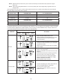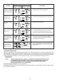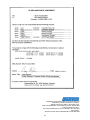
1
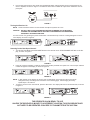
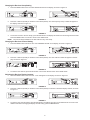
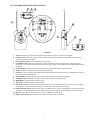
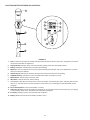
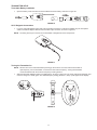
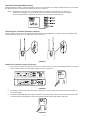
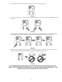
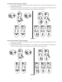
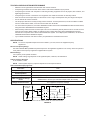
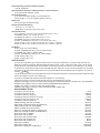
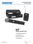
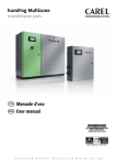
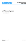
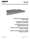
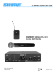
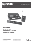
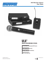
ULX Wireless System
User Guide
6-9¥
8*3&-&44.*$301)0/&4:45&.4
�������������������������������������������
6MUSB8JEF#BOE'SFRVFODZ"HJMF6)'4ZTUFNT
������������������������������
"VUP'SFRVFODZ4FMFDUJPO"'4
������������������������������������
����������������������
3FMJBCMF1SPGFTTJPOBM4PVOE2VBMJUZ
.VMUJ4ZTUFN0QFSBUJPO
27EN8732E (Rev. 8)
©2006, Shure Incorporated
Printed in U.S.A.
CONTENTS
ULX SYSTEM COMPONENTS........................................................................................................................... 3
ULXS4 STANDARD RECEIVER FEATURES AND CONTROLS........................................................................ 4
Front Panel . ....................................................................................................................................................................4
Rear Panel ......................................................................................................................................................................4
ULXP4 PROFESSIONAL RECEIVER FEATURES AND CONTROLS............................................................... 5
Front Panel . ....................................................................................................................................................................5
Rear Panel ......................................................................................................................................................................5
SINGLE SYSTEM SETUP ................................................................................................................................. 6
Receiver Connections .....................................................................................................................................................6
Turning the Receiver On..................................................................................................................................... 7
Scanning for the Next Open Channel .............................................................................................................................7
Changing the Receiver Group Setting ............................................................................................................................8
Changing the Receiver Channel Setting .........................................................................................................................8
Adjusting the Receiver Display Contrast .........................................................................................................................8
ULX1 TRANSMITTER FEATURES AND CONTROLS . ..................................................................................... 9
ULX2 TRANSMITTER FEATURES AND CONTROLS...................................................................................... 10
TRANSMITTER SETUP ....................................................................................................................................11
Transmitter Battery Installation . .................................................................................................................................... 11
ULX1 Bodypack Connections ....................................................................................................................................... 11
Turning the Transmitter On ........................................................................................................................................... 11
ULX1 Bodypack Transmitter Attenuation Settings . .......................................................................................... 12
Setting the Transmitter Operating Frequency .................................................................................................. 12
SYSTEM OPERATION . ................................................................................................................................... 14
Transmitter Gain Adjustment . .......................................................................................................................................14
Locking Transmitter Frequency Settings .......................................................................................................................15
Unlocking Transmitter Frequency Settings ...................................................................................................................15
Locking the Power On/Off Switch .................................................................................................................................16
Unlocking the Power On/Off Switch ..............................................................................................................................16
ADVANCED PROGRAMMING MODE (ULXP4 MODELS ONLY) Scanning Frequency Groups . ................... 16
Adjusting the Receiver Squelch Setting ........................................................................................................................17
Locking the Receiver . ...................................................................................................................................................18
Unlocking the Receiver .................................................................................................................................................18
RECEIVER INSTALLATION ............................................................................................................................. 19
Table Mounting the ULXS4 Standard Receiver . ...........................................................................................................19
Rack Mounting a ULXP4 Professional Receiver ...........................................................................................................19
Rack Mounting Dual ULXP4 Receivers ........................................................................................................................20
TIPS FOR ACHIEVING OPTIMUM PERFORMANCE ..................................................................................... 21
SPECIFICATIONS . .......................................................................................................................................... 21
CERTIFICATION .............................................................................................................................................. 23
REPLACEMENT PARTS .................................................................................................................................. 23
FURNISHED ACCESSORIES . ........................................................................................................................ 24
OPTIONAL ACCESSORIES . ........................................................................................................................... 24
BATTERY LIFE . ............................................................................................................................................... 24
TROUBLESHOOTING ..................................................................................................................................... 25
LICENSING INFORMATION ............................................................................................................................ 26
LIMITED TWO-YEAR WARRANTY ................................................................................................................. 27
DECLARATION OF CONFORMITY ................................................................................................................. 27
ULX SYSTEM COMPONENTS
ULXS4
ULX1
ULXP4
ULX2
FIGURE 1
Each Shure ULX® Wireless System includes the following components, as shown in Figure 1:
ULX1 Body-Pack Transmitter with a lavalier microphone, instrument adapter cable, or headworn microphone
or a
ULX2 Hand-Held Microphone Transmitter with an interchangeable Shure microphone head
and a
ULXS4 Standard Diversity Receiver
or a
ULXP4 Professional Diversity Receiver with rack-mounting hardware
or a
ULXP4D Dual Professional Diversity Receivers with rack-mounting hardware and center link brackets
ULXS4 STANDARD RECEIVER FEATURES AND CONTROLS
FIGURE 2
Front Panel
1. “RF” Indicator. Glows green to indicate presence of received Radio Frequency (RF) signal.
2. “TX Audio” Level Indicators. Indicate transmitted (TX) audio signal strength. Green indicates normal operation.
Amber indicates approaching overload condition. Red indicates excessive audio levels.
3. Receiving Antenna Indicator. Appears on the left or right side of the display, depending on which antenna is receiving the strongest RF signal.
4. GROUP Display. Indicates the pre-selected compatible Frequency Group number in which the system is operating.
5. CHANNEL Display. Indicates the current Channel number within the Frequency Group.
6. Transmitter Battery Life Indicator. Displays the remaining transmitter battery life when the transmitter is turned on.
7. SCAN Indicator. Appears when Scan Channel Mode is active.
8. TV Channel/Volume Level Indicator. Shows volume level and UHF TV channel in small digits (U.S. only).
9. MODE Button. Press this button to step through the display menu.
10. SET Button. Saves the altered setting.
11.
Button. Press this button to increase or decrease the Volume level, Group/Channel settings or the
display contrast level.
12. Power On/Off Switch. Turns the receiver on and off.
Rear Panel
13. Power Connector. Accepts power from the supplied AC adapter, or from any filtered 14–18 Vdc (550 mA minimum)
supply. It also accepts dc power from a Shure UA844 Antenna Distribution System.
14. Output Connector (XLR balanced Low Z). Provides balanced low–impedance mic level or line level output.
15. Mic/Line Switch. Selects output of XLR balanced Low Z connector. It can be set for microphone (–27 dBV) or
line–level (+4.3 dBV). The Mic/Line switch does not affect the output of the unbalanced 1/4 inch phone jack.
16. Output Connector (High Z Unbalanced 1/4 inch Phone Jack). Provides unbalanced high impedance auxiliary
level output.
17. Antenna Input Connectors. BNC–type connectors provide connection to the supplied antennas. They also provide
12 Vdc output power for use with remotely located antennas.
ULXP4 PROFESSIONAL RECEIVER FEATURES AND CONTROLS
FIGURE 3
Front Panel
1.
Receiving Antenna Indicators. One of these amber LEDs will glow , depending on which antenna is receiving the
strongest Radio Frequency (RF) signal.
2.
SQUELCH Indicator. Appears when the Squelch Level Mode is selected.
3.
SCAN Indicator. Appears when the receiver is scanning for an open Group or Channel.
4.
Volume Level Warning Indicator. Indicates a discrepancy between the Volume control knob position and the previously locked Volume Level setting.
5.
TV Channel Display. Indicates the UHF TV channel in which the system is operating (U.S. only).
6.
Transmitter Battery Life Indicator. Displays the remaining transmitter battery life when the transmitter is turned on.
7.
Volume Lock Indicator. Appears after the Volume level setting has been locked.
8.
RF Level Indicators. Indicate received RF signal strength.
9.
“TX Audio” Level Indicators. Indicate transmitted (TX) audio signal strength. Green indicates normal operation.
Amber indicates approaching overload condition. Red indicates excessive audio levels.
10. GROUP Display. Indicates the pre-selected Frequency Group number in which the system is operating.
11. CHANNEL Display. Indicates the current Channel number within the Frequency Group.
12. FREQUENCY Display. Indicates the current frequency in megahertz (MHz).
13. Frequency Lock Indicator. Appears when the Frequency has been locked.
14. MODE Button. Press this button to step through the display menu.
15. SET Button. Saves the altered setting.
16. Display Control Knob. Rotate this knob to change the Group/Channel settings, the Squelch setting, or to scan a
Group or Channel.
17. Level Control. Adjusts the receiver audio output level to match the required input levels of a mixer or amplifier. Normally, this control is set fully clockwise.
18. Power On/Off Switch. Turns the receiver on and off.
Rear Panel
19. Power Connector. Accepts power from the supplied AC adapter, or from any filtered 14–18 Vdc (550 mA minimum)
supply. It also accepts DC power from a Shure UA844 Antenna Distribution System.
20. Output Connector (XLR balanced Low Z). Provides balanced low–impedance mic level or line level output.
21. Mic/Line Switch. Selects output of XLR balanced Low Z connector. It can be set for microphone (–27 dBV) or line
level (+4.3 dBV). This switch does not affect the output of the unbalanced 1/4 inch phone jack.
22. Output Connector (High Z Unbalanced 1/4 inch Phone Jack). Provides unbalanced high impedance auxiliary
level output.
23. Antenna Input Connectors. BNC–type connectors provide connection to the supplied antennas. They also provide
12 Vdc output power for use with remotely located antennas.
SINGLE SYSTEM SETUP
Receiver Connections
NOTE: If you are installing multiple ULXP4 Professional systems, or systems with multiple ULXP4 receivers,
refer also to the Advanced Programming section of this manual.
1. Plug the dc power supply into the power connector on the back of the receiver, as shown in Figure 4. Connect the
other end of the power supply into an electrical outlet.
FIGURE 4
2. Attach the two antennas to the ANTENNA connectors, as shown in Figure 5. The ULXS4 is supplied with 1/4 wave
antennas; the ULXP4 is supplied with 1/2 wave antennas.
ULXS4
ULXP4
FIGURE 5
3. Connect audio cable(s) (not supplied) from the audio output(s) to the audio input(s) of your audio system, mixer and/
or amplifier, as shown in Figure 6.
ULXP4
ULXS4
Figure 6
4. If the receiver XLR output is used, make sure the MIC/LINE switch setting matches the input requirements of the
mixer or amplifier, as shown in Figure 7. The Mic/Line switch does not affect the output of the unbalanced 1/4 inch
phone jack.
MIC
LINE
FIGURE 7
Turning the Receiver On
NOTE: These instructions assume no other wireless microphone systems are in use.
CAUTION: Do NOT turn on the transmitter before powering up the receiver.
Turning the transmitter on first will interfere with the receiver’s
frequency scanning function.
Turn the receiver on by pressing the power On/Off switch. The default Group 1 Channel 1 setting will appear on the receiver display, as shown in Figure 8.
FIGURE 8
Scanning for the Next Open Channel
1. To enter the Scan Mode, press the MODE button on the receiver once. SCAN CHANNEL will flash on the display, as shown in Figure 9.
FIGURE 9
2. Press the or buttons (ULXS4) or rotate the control knob (ULXP4) clockwise one quarter turn. The next open Channel
number will appear on the display, as shown in Figure 10.
FIGURE 10
NOTE: If “NO” appears on the display, the receiver has not detected an open Channel in the current Group.
Change the Group according to the instructions on the following page. After changing the Group,
repeat Steps 1 and 2 above.
3. To tune the receiver to the new Channel, press the SET button. The display will return to the default mode, as shown
in Figure 11.
FIGURE 11
THE RECEIVER IS NOW READY TO USE.
UNLESS THE RECEIVER IS MOVED TO A DIFFERENT LOCATION, THIS PROCEDURE DOES
NOT NEED TO BE REPEATED. PROCEED TO TRANSMITTER SETUP SECTION.
Changing the Receiver Group Setting
1. Press the MODE button twice. The word GROUP will flash on the display, as shown in Figure 12.
FIGURE 12
2. Press the or buttons (ULXS4) or rotate the control knob (ULXP4). The new frequency Group number will appear on
the display, as shown in Figure 13.
FIGURE 13
3. To tune the receiver to the new Group, press the SET button. The display will advance to the Change Channel mode.
Press the MODE button once more to return to the default mode.
NOTE: The receiver always defaults to the first Channel in any new Group.
Changing the Receiver Channel Setting
1. Press the MODE button three times. The word CHANNEL will flash on the display, as shown in Figure 14.
FIGURE 14
2. Press the or buttons (ULXS4) or rotate the control knob (ULXP4). The new Channel number will appear on the display, as shown in Figure 15.
FIGURE 15
3. To save the new Channel, press the SET button. The receiver will then return to the default mode.
Adjusting the Receiver Display Contrast
1. Press the MODE button for two seconds. “LCD” will appear on the display, as shown in Figure 16.
FIGURE 16
2. Press the or buttons (ULXS4) or rotate the control knob (ULXP4) to increase or decrease display contrast, as shown
in Figure 17.
FIGURE 17
3. To save the new Contrast setting, press the SET button. The display will return to the default mode. To return to the
default mode without changing the display contrast setting, press the MODE button.
ULX1 TRANSMITTER FEATURES AND CONTROLS
FIGURE 18
1.
Antenna. A flexible 1/4 wave antenna is permanently attached to the top of the ULX1 transmitter.
2.
Input Connector. This TA4F miniature four-pin connector mates with a variety of Shure lavalier, instrument and
headset microphones and cables.
3.
Power ON/OFF Switch. Turns transmitter power on and off.
4.
Power/Battery LED. When the Power switch is in the ON position, this LED will glow green, indicating that the
transmitter is on. This LED will turn red when the battery is low. Refer to the “Checking the Transmitter Battery Power”
paragraph.
5.
Display Window. Displays Group and Channel setting, battery power level, and PEAK indicator.
6.
Battery Level Icon. Indicates amount of battery life remaining.
7.
PEAK Icon. This icon appears when audio input signal overloads the transmitter. The icon is displayed for 2 seconds
after the input overload is detected.
8.
GROUP Display. Indicates the frequency Group number in which the transmitter is operating.
9.
CHANNEL Display. Indicates the current Channel number within the frequency Group.
10. MODE Button. Selects Group or Channel mode.
11. SET Button. Changes Group or Channel setting.
12. Audio Gain Control. Changes the audio level sensitivity to accommodate various sound sources (e.g. loud singing,
soft speaking, or musical instrument). Refer to the “Transmitter Gain Adjustment” paragraph.
13. Input Attenuation Switch. Selects either 0 dB or –20 dB attenuation. Use the 0 dB position for voice and low output
instruments. Use the 20 dB pad position for high output instruments such as electric guitars with active electronics.
14. Belt Clip. Allows the transmitter to be worn on a belt, waistband, or guitar strap.
15. Battery Compartment Cover. Hinged cover opens to provide access to 9V battery.
ULX2 TRANSMITTER FEATURES AND CONTROLS
FIGURE 19
1.
Grille. Protects the microphone cartridge and helps reduce breath sounds and wind noise. The grilles of the various
microphone heads differ in appearance.
2.
Display Window. Displays Group and Channel setting, battery power level, and PEAK indicator.
3.
Battery Level Icon. Indicates amount of battery life remaining.
4.
PEAK Icon. This icon appears when the input signal overloads the transmitter. The icon is displayed for 2 seconds
after input overload is detected.
5.
GROUP Display. Indicates the frequency Group number in which the transmitter is operating.
6.
CHANNEL Display. Indicates the current Channel number within the frequency Group.
7.
MODE Button. Selects Group or Channel mode.
8.
SET Button. Changes Group or Channel setting.
9.
Power/Battery LED. When the Power switch is in the ON position, this LED will glow green, indicating that the transmitter is on. This LED will turn red when the battery is low. Refer to the “Checking the Transmitter Battery Power”
paragraph.
10. Power ON/OFF Switch. Turns the transmitter on and off.
11. Audio Gain Control. Changes the audio level sensitivity to accommodate various sound sources (e.g. loud singing
or soft speaking). Refer to the “Transmitter Gain Adjustment” paragraph).
12. 9 V Battery. Provides power to the transmitter and microphone.
13. Battery Cover. Unscrews to expose battery and Gain control.
10
TRANSMITTER SETUP
Transmitter Battery Installation
1.
Open the battery cover and insert a fresh 9V alkaline or lithium battery, as shown in Figure 20.
FIGURE 20
ULX1 Bodypack Connections
1.
If you are using a Bodypack system with a Shure lavalier microphone or instrument adapter, plug the microphone
cable or instrument adapter cable into the transmitter input connector, as shown in Figure 21.
NOTE: The wiring of the input connector on the transmitter is designed for Shure microphones.
FIGURE 21
Turning the Transmitter On
NOTE: DO NOT turn on the transmitter before powering up the receiver. Once the receiver has located an
open frequency, turn the transmitter on and set it to that receiver frequency. Turning the transmitter
on first will interfere with the receiver’s frequency scanning function.
1. Slide the transmitter ON/OFF switch to the ON position, as shown in Figure 22. The power LED will momentarily glow
red, then change to a steady green. The default frequency setting (Channel 1, Group 1) will appear on the display.
FIGURE 22
11
Checking Transmitter Battery Power
With the transmitter turned on, observe the Battery Level icon on the display. The number of shaded bars on the icon indicate
the approximate amount of battery life remaining, as shown in Figure 23.
NOTE: Stated battery life is based on a 9V alkaline battery. For details on other battery types, refer to the
“Battery Life” paragraph, or go to the Shure web site at www.shure.com and refer to the FAQ section.
Once the empty battery icon appears, the tone key turns off and the receiver will mute.
FIGURE 23
ULX1 Bodypack Transmitter Attenuation Settings
If using a lavalier microphone, make sure the Attenuator switch is in the 0 dB position. If using an instrument adapter cable,
slide the Attenuator switch to the –20 dB position. Refer to Figure 24.
FIGURE 24
Setting the Transmitter Operating Frequency
1.
Note the Group number and Channel number on the receiver display. Press and hold the MODE button until only the
Group number is visible on the transmitter display, as shown in Figure 25.
FIGURE 25
2.
If necessary, press the transmitter SET button to advance the Group number until it matches the Group number on
the receiver display.
3.
Press the transmitter MODE button again to select the new Group setting and move to the Channel selection mode.
The Group number will disappear, and only the Channel number will be visible. Refer to Figure 26.
FIGURE 26
12
4. Press the SET button to advance to the desired Channel number, as shown in Figure 27.
FIGURE 27
5.
To reverse the direction of the Group or Channel search, hold down the SET button and press the MODE button. See
Figure 28.
FIGURE 28
6.
Press the MODE button again to select the new Channel setting. “FrCh” will appear briefly on the display, indicating
that the frequency has changed. Then the new Group and Channel settings will appear. Refer to Figure 29.
FIGURE 29
7.
Make sure the transmitter Group and Channel settings match the receiver Group and Channel settings, as shown in
Figure 30. If using the Bodypack transmitter, clip it to your belt, waistband, or guitar strap.
ULXS4
ULXP4
FIGURE 30
THE TRANSMITTER IS NOW READY TO USE. FOR MULTIPLE SYSTEM INSTALLATIONS,
LEAVE THE TRANSMITTER ON, RETURN TO THE “BASIC RECEIVER PROGRAMMING,” AND
REPEAT THE SETUP PROCEDURE FOR EACH SYSTEM.
13
SYSTEM OPERATION
Speak into the microphone or play your instrument. If your audio system is properly set and functioning, you should hear the
sound of your voice or instrument coming through the loudspeakers. The LEDs on the receiver should also illuminate. The top
TX AUDIO LED is red and should only illuminate momentarily when you speak loudly or play your instrument loudly. Refer to
Figure 31.
ULXS4
ULXP4
FIGURE 31
Transmitter Gain Adjustment
If necessary, adjust the transmitter gain with the supplied screwdriver, as shown in Figure 32, until only the green and yellow
Audio LEDs on the receiver illuminate when you speak into the microphone or play your instrument. The red LED should only
illuminate momentarily when you speak loudly or play your instrument loudly.
FIGURE 32
14
Locking Transmitter Frequency Settings
1.
Refer to Figure 33. Slide the transmitter power switch to the OFF position and wait for the display light to turn off.
2.
Hold down the SET button.
3.
Slide the power switch back to the ON position. “Fr L” will appear on the transmitter display, indicating that the frequency setting is locked. The locked frequency Group and Channel will then appear.
ULX1
1
ULX2
3
2
2
1
4
3
5
4
5
FIGURE 33
Unlocking Transmitter Frequency Settings
1.
Refer to Figure 34. Slide the transmitter power switch to the OFF position and wait for the display light to turn off.
2.
Hold down the SET button.
3.
Slide the power switch back to the ON position. “Fr UL” will appear on the transmitter display, indicating that the
frequency setting is unlocked. The current frequency Group and Channel will then appear.
ULX1
1
ULX2
3
2
2
1
4
3
5
FIGURE 34
15
4
5
Locking the Power On/Off Switch
1.
Turn the transmitter on by sliding the power switch to the ON position.
2.
While holding down the SET button, press and hold the MODE button for four seconds. “Po L” will appear on the
display. See Figure 35. This display indicates that the Power On/Off switch is locked. The transmitter will remain on,
even when the power ON/OFF switch is moved to the OFF position.
NOTE: Make sure both buttons are depressed when trying to lock the transmitter.
ULX1
ULX2
1
2
3
1
2
3
FIGURE 35
Unlocking the Power On/Off Switch
1.
Verify that the power transmitter ON/OFF switch is in the ON position.
2.
While holding down the transmitter SET button, press and hold the MODE button for four seconds. “Po UL” will appear on the display. See Figure 36. This display indicates that the Power On/Off switch is unlocked. The transmitter
will then return to normal operating mode.
NOTE: Make sure both buttons are depressed when trying to unlock the transmitter.
ULX1
ULX2
1
2
3
1
Figure 36
16
2
3
ADVANCED PROGRAMMING MODE (ULXP4 MODELS ONLY) Scanning Frequency Groups
1.
Hold down the receiver SET button and press the MODE button once. The words GROUP and SCAN will flash on the
display. Refer to Figure 37.
FIGURE 37
2.
To begin scanning, rotate the control knob one quarter turn clockwise, as shown in Figure 38. The receiver will automatically begin scanning each Channel in all Groups. This may take up to two minutes, and the word “BUSY” will
appear on the display.
FIGURE 38
3.
When all Groups have been scanned, the Group with the most open Channels will appear on the display, as shown in
Figure 39.
FIGURE 39
4.
To tune the receiver to the new Group, press the SET button. An open Channel in this Group will automatically be
scanned and saved in the background. The display will then return to the default mode, as shown in Figure 40. If you
choose not to accept the receiver’s recommended Group, rotate the control knob to the right to scroll through the list
of scanned groups.
FIGURE 40
Adjusting the Receiver Squelch Setting
The receiver squelch control is factory preset for optimum performance. Normally, no further adjustment is required. However, it is possible to adjust the squelch control to improve either signal quality or increase system range.
NOTE: Increasing the Squelch level causes the receiver to demand a higher quality signal (less noise before
muting), but it reduces operating range. Decreasing the Squelch level allows a lower quality signal
through (more noise before muting), but extends the operating range.
1.
Hold down the receiver SET button and press the MODE button twice. “SQLCH” will flash on the display, as shown in
Figure 41.
FIGURE 41
17
2. Rotate the control knob. The new Squelch setting will appear on the display, as shown in Figure 42.
FIGURE 42
3. To accept the new Squelch value, press the SET button. The display will then return to the Default Mode, press
the MODE button again.
Locking the Receiver
You can lock the ULXP4 receiver frequency and output level to prevent unauthorized or accidental changes to the settings. To
access the Lock functions, proceed as follows:
1. Hold down the receiver SET button and press the MODE button three times. “Loc” will appear on the receiver display.
See Figure 43.
FIGURE 43
2. Rotate the control knob until one or both of the lock icons flashes on the receiver display, as shown in Figure 44.
FIGURE 44
3. To activate the flashing lock icon(s), press the SET button. The display will return to the default mode and the
lock icon will appear on all display screens. See Figure 44.
FIGURE 45
Unlocking the Receiver
To unlock the ULXP4 receiver frequency and output level settings, hold down the SET button and rotate the control knob
one quarter turn left-right-left. The lock icon(s) will disappear, indicating that the receiver is unlocked. See Figure 45.
FIGURE 46
NOTE: If the volume control knob has been set to a level higher than the locked level, the output level will
remain locked and the Volume Level warning indicator will flash on the receiver display. See Figure
46. Rotate the volume control knob counterclockwise until the Volume Level warning indicator stops
flashing. This will unlock the output level setting.
FIGURE 47
18
RECEIVER INSTALLATION
Table Mounting the ULXS4 Standard Receiver
To mount a ULXS4 Standard receiver on a table or other horizontal surface, attach the four adhesive bumpers to the bottom
corners of the receiver and place the receiver on the mounting surface. See Figure 47.
FIGURE 48
NOTE: The ULXS4 can also be rack mounted, using one of the Rack Mount Kits listed on page 24.
Rack Mounting a ULXP4 Professional Receiver
1.
Align the supplied rack-mount brackets over the holes on each side of the receiver, as shown in Figure 48.
2.
Fasten the brackets to the receiver by installing the eight screws supplied with the mounting brackets.
CAUTION: Do not overtighten the screws. Doing so may damage the printed circuit
boards.
1/4 IN.
FIGURE 49
3.
Slide the receiver into an 19-inch audio equipment rack, as shown in Figure 49.
4.
Secure the rack-mount brackets to the rack using the four supplied screws.
5.
If you are not front mounting the antennas, insert the plastic plugs into the bracket holes.
NOTE: Front–mounting the antennas requires the UA600 Front Mount Antenna Kit listed on page 24.
FIGURE 50
19
Rack Mounting Dual ULXP4 Receivers
1.
Align the receivers side by side so that the front panels both face the same direction.
2.
Place the supplied straddle bars in the recesses on the top and bottom of the receivers, so that the bars overlap both receivers. Refer to Figure 50.
1/4 IN.
FIGURE 51
3.
Secure the straddle bars to the receivers using the supplied screws. CAUTION: Do not overtighten the screws. Doing
so may damage the printed circuit boards.
4.
Position the rack-mount brackets over the holes in the sides of each receiver, as shown in Figure 51.
5.
Secure the brackets to the receivers with the supplied screws.
1/4 IN.
FIGURE 52
6.
Slide the linked receivers into a 19-inch audio equipment rack, as shown in Figure 52.
7.
Secure the brackets to the rack using all four of the supplied screws.
FIGURE 53
NOTE: To front mount or combine antennas, use the optional accessories listed on page 24.
20
TIPS FOR ACHIEVING OPTIMUM PERFORMANCE
•
Maintain a line of sight between the transmitter and receiver antennas.
•
Avoid placing transmitter and receiver where metal or other dense materials may be present.
•
Avoid placing the receiver near computers or other RF generating equipment such as CD players, DAT machines, and
digital signal processors.
•
Avoid placing the receiver in the bottom of an equipment rack unless the antennas are remotely located.
•
Point the receiver antenna tips away from each other at a 45° angle, and keep them away from large metal objects.
•
Do not obstruct the receiver antennas.
•
Use the proper cable when remotely locating receiver antennas. For best performance, use Shure UA825 or UA850
low loss coaxial antenna cable, or 50 ohm low loss cable such as RG-8U.
•
For remote antenna placement, use Shure UA820WB 1/2 Wave Antenna and UA830WB Active Remote Antenna Kits,
along with Shure UA844WB Antenna Distribution System.
•
Mount diversity antennas at least 1/4 wave apart. This can be achieved by remote placement of one or both 1/2 wave
antennas using Shure UA825, UA850, or UA8100 low loss coaxial cable and a Shure UA830WB Active Remote
Antenna Kit in conjunction with a Shure Antenna Distribution System. For multiple system installations, use the Shure
UA844WB Antenna/Power Distribution System.
•
Try to maintain a distance of at least 5 meters (15 ft) between the transmitter and receiver.
SPECIFICATIONS
NOTE: For a list of compatible frequencies that are usable in your area, refer to the supplied frequency
supplement.
RF Carrier Frequency Range
554.000 to 865.000 MHz (Available frequencies depend on the applicable regulations in the country where the system is
used). Refer to the frequency supplement supplied with the system.
Effective Range
100 m (300 ft.) under optimal conditions
NOTE: Actual working range depends on RF signal absorption, reflection, and interference
Audio Frequency Response
25 to 15,000 Hz, ±2 dB
NOTE: Overall system frequency response depends on the microphone element.
ULX1 Transmitter Input (Figure 54)
Connector:
TA4F
Input Configuration:
Unbalanced, active
Actual Impedance:
18 kΩ with lavalier microphone 1 MΩ with instrument cable
Maximum Input Level:
10 Vp–p (12 dBV) for 1% THD at minimum gain setting using 1 kHz signal.
TA4F Connector Pin Assignments:
Pin 1: Tied to Ground Pin 2: Tied to +5 V Pin 3: Tied to Audio Pin 4: Tied thru
20kΩ Resistor to Ground. (On instrument adapter cable, Pin 4 floats)
Voltage for Remote Power:
+5 V supplied to microphone cartridge
MICROPHONE
ELEMENT
ULX1 MIC JACK BOARD
500 :
2
2
4
4
3
3
+5 V
27 pF
20K :
500 :
AUDIO
27 pF
1
1
NOTE: LAVALIER MIC TIES PINS 3 AND 4 TOGETHER; THE GUITAR CABLE DOES NOT.
FIGURE 54
21
GROUND
ULX1 Transmitter Output
Actual Impedance:
50 Ω
Nominal Output Level:
20 mW
Maximum Output Level:
30 mW
Pin Assignments:
Shell = Ground Center = Signal
ULX2 Transmitter Input
Input Configuration:
Actual Impedance:
Maximum Input Level:
Unbalanced, active
20 kΩ
10 Vp–p (12 dBV) for 1% THD at minimum gain setting using 1 kHz
signal.
ULX2 Transmitter Output
50 Ω
Actual Impedance:
Nominal Output Level:
Maximum Output Level:
Pin Assignments:
20 mW
30 mW
Shell = Ground Center = Signal
ULXS4 and ULXP4 Receiver Input
Connector:
Antenna
Power Input
Connector Type:
BNC
IEC 320
Actual Impedance:
Nominal Input Level:
Maximum Input Level:
Pin Assignments:
Voltage for Remote Power:
50 Ω
––
–95 to –30 dBm
15 Vdc
+6 dBm (–20 dBm recommended)
18 Vdc
Shell = Ground Center = Signal
IEC Standard
12 Vdc, 150 mA maximum
––
ULXS4 and ULXP4 Receiver Output
Connector:
High Z Audio
Low Z Audio*
Output Configuration:
Unbalanced (1/4 in.)
Balanced (XLR)
Actual Impedance:
Nominal Input Level:
Pin Assignments:
3 kΩ
22 Ω
––
––
Tip = Hot Ring/ Sleeve = Gnd
1 = Ground
2 = Hot
3 = Cold
Yes
Voltage/Current/Phantom
Power Protection?
Yes
*Output Level: Microphone Level = Line Level – 20 dB
Transmitter Audio Polarity
Positive pressure on microphone diaphragm (or positive voltage applied to tip of WA302 phone plug) produces positive
voltage on pin 2 (with respect to pin 3 of low impedance output) and the tip of the high impedance 1/4-inch output
Transmitter Gain Adjustment Range
ULX1: 25 dB
ULX2: 25 dB
Receiver Audio Output Level (±38 kHz deviation, 1 kHz tone)
XLR connector (into 600 ohm load): +3.9 dBV (line), –17 dBV (mic)
1/4 inch connector (into 3000 ohm load): –2 dBV
Impedance
ULX1 (input): 1 Megohm ULXS4, ULXP4 (output): 50 ohms at line level; 2000 ohms at mic level
Modulation
±38 kHz deviation compressor-expander system with pre- and de-emphasis.
RF Power Output
ULX1, ULX2: 30 mW maximum
Dynamic Range
>100 dB, A-weighted
RF Sensitivity
1.26 μV for 12 dB SINAD (typical)
Image Rejection
80 dB typical
Spurious Rejection
75 dB typical
22
Ultimate Quieting (reference ±38 kHz deviation)
>105 dB, A-weighted
System Distortion (reference ±38 kHz deviation, 1 kHz modulation)
0.3% total harmonic distortion, typical
Power Requirements
ULX1, ULX2: 9V alkaline battery; 8.4 V Nicad optional
ULXS4, ULXP4: 14 - 18 Vdc (negative ground), 550 mA
Battery Life
8 to 9 hours (with 9V alkaline battery)
Operating Temperature Range
- 20° to 49° C (- 4° to 120° F)
NOTE: Battery characteristics may limit this range.
Overall Dimensions
ULX1: 96.5 mm H x 67 mm W x 26.7 mm D (3.86 x 2.68 x 1.10 in.)
ULX2/SM58: 228.6 L x 51 mm Dia. (9 x 2 in)
ULX2/BETA 58: 220.9 mm L x 51 mm Dia. (8.7 x 2 in.)
ULX2/SM86: 213 mm L x 49 mm Dia. (8.4 in x 1.9 in)
ULX2/87, ULX2/BETA 87: 223.5 mm L x 51 mm Dia. (8.8 x 2 in.)
ULX4S: 43 mm H x 214 mm W x 163 mm D (1.72 in. x 8.56 in. x 6.52 in.)
ULX4P: 43 mm H x 214 mm W x 172 mm D (1.72 in. x 8.56 in. x 6.88 in.)
Net Weight
ULX1: 79 g (2.8 oz.) without battery
ULX2/58, ULX2/BETA 58: 289 g (10.2 oz.) without battery
ULX2/SM86: 251 g (8.8 oz.) without battery
ULX2/87, ULX2/BETA 87: 258 g (9.1 oz.) without battery
ULXS4: 1049 g (2 lbs, 5 oz.)
ULXP4: 1105 g (2 lbs, 7 oz.)
CERTIFICATION
ULX1,ULX2 Transmitters: Type Accepted under FCC Part 74 and 90. Certified by IC in Canada under RSS-123 and
RSS-102. Conforms to European ETSI standards EN-300 422, Parts 1 and 2, and ETS 301 489, Parts 1 and 9. ULX4S,
ULX4P Receivers: Authorized under the Declaration of Conformity provision of FCC Part 15A. Certified by IC in Canada
under RSS-123. Conforms to European ETSI standards ETS 301 489, Parts 1 and 9. The Shure Models ULX1 and ULX2
Transmitters meet the essential requirements of the European R&TTE Directive 99/5/EC and are eligible to carry the CE
O682
marking.
The Shure Models ULXS4 and ULXP4 Receivers meet the essential requirements of the European R&TTE Directive 99/5/
EC and are eligible to carry the CE marking.
Conforms to Australian EMC requirements and is eligible for C–Tick marking.
PS40 Power Supply: Conforms to safety standard UL1310. Canada/CSA 22 2 No. 223.
PS40AR Power Supply: Conforms to safety standard IEC60065. Certified TÜV Rheinland, Argentina, S.A. No. RA2681022.
PS40AZ Power Supply: Conforms to safety standard AS/NZS60065:2003 (Q050515)
PS40E Power Supply: Conforms to safety standard EN 60950.
PS40UK Power Supply: Conforms to safety standard EN 60950 and BS 7002.
REPLACEMENT PARTS
AC Adapter (120 VAC, 60 Hz) . . . . . . . . . . . . . . . . . . . . . . . . . . . . . . . . . . . . . . . . . . . . . . . . . . . . . . . . . . . . . . . . . PS40
AC Adapter (220 VAC, 50 Hz) . . . . . . . . . . . . . . . . . . . . . . . . . . . . . . . . . . . . . . . . . . . . . . . . . . . . . . . . . . . . . . . PS40AR
AC Adapter (230 VAC, 50/60 Hz). . . . . . . . . . . . . . . . . . . . . . . . . . . . . . . . . . . . . . . . . . . . . . . . . . . . . . . . . . . . . PS40AZ
AC Adapter (230 VAC, 50/60 Hz, Europlug). . . . . . . . . . . . . . . . . . . . . . . . . . . . . . . . . . . . . . . . . . . . . . . . . . . . . . PS40E
AC Adapter (230 VAC, 50/60 Hz, UK) . . . . . . . . . . . . . . . . . . . . . . . . . . . . . . . . . . . . . . . . . . . . . . . . . . . . . . . . . PS40UK
AC Adapter (100 VAC, 50/60 Hz). . . . . . . . . . . . . . . . . . . . . . . . . . . . . . . . . . . . . . . . . . . . . . . . . . . . . . . . . . . . . . PS40J
SM58® Cartridge with Grille (ULX2/58). . . . . . . . . . . . . . . . . . . . . . . . . . . . . . . . . . . . . . . . . . . . . . . . . . . . . . . . RPW112
BETA 58A® Cartridge with Grille (ULX2/BETA 58) . . . . . . . . . . . . . . . . . . . . . . . . . . . . . . . . . . . . . . . . . . . . . . . RPW118
SM86 Cartridge with Grille (ULX2/SM86). . . . . . . . . . . . . . . . . . . . . . . . . . . . . . . . . . . . . . . . . . . . . . . . . . . . . . RPW114
SM87A Cartridge with Grille (ULX2/87). . . . . . . . . . . . . . . . . . . . . . . . . . . . . . . . . . . . . . . . . . . . . . . . . . . . . . . . RPW116
BETA 87A Cartridge with Grille (ULX2/BETA 87A). . . . . . . . . . . . . . . . . . . . . . . . . . . . . . . . . . . . . . . . . . . . . . . RPW120
BETA 87C Cartridge with Grille (ULX2/BETA 87C) . . . . . . . . . . . . . . . . . . . . . . . . . . . . . . . . . . . . . . . . . . . . . . RPW122
Matte Silver Grille for SM58®. . . . . . . . . . . . . . . . . . . . . . . . . . . . . . . . . . . . . . . . . . . . . . . . . . . . . . . . . . . . . . . . RK143G
Matte Silver Grille for SM86. . . . . . . . . . . . . . . . . . . . . . . . . . . . . . . . . . . . . . . . . . . . . . . . . . . . . . . . . . . . . . . . . RPM266
Matte Silver Grille for BETA 58A®. . . . . . . . . . . . . . . . . . . . . . . . . . . . . . . . . . . . . . . . . . . . . . . . . . . . . . . . . . . . RK265G
Matte Silver Grille for BETA 87A. . . . . . . . . . . . . . . . . . . . . . . . . . . . . . . . . . . . . . . . . . . . . . . . . . . . . . . . . . . . . . . RK312
Matte Silver Grille for BETA 87C . . . . . . . . . . . . . . . . . . . . . . . . . . . . . . . . . . . . . . . . . . . . . . . . . . . . . . . . . . . . . . RK312
Black Grille for SM87A . . . . . . . . . . . . . . . . . . . . . . . . . . . . . . . . . . . . . . . . . . . . . . . . . . . . . . . . . . . . . . . . . . . . RK214G
Black Grille for BETA 58A. . . . . . . . . . . . . . . . . . . . . . . . . . . . . . . . . . . . . . . . . . . . . . . . . . . . . . . . . . . . . . . . . RPM323G
Black Grille for BETA 87A and BETA 87C . . . . . . . . . . . . . . . . . . . . . . . . . . . . . . . . . . . . . . . . . . . . . . . . . . . . RPM324G
23
Belt Clip . . . . . . . . . . . . . . . . . . . . . . . . . . . . . . . . . . . . . . . . . . . . . . . . . . . . . . . . . . . . . . . . . . . . . . . . . . . . . . 44A8013A
1/4-Wave Antenna (554 - 698 MHz). . . . . . . . . . . . . . . . . . . . . . . . . . . . . . . . . . . . . . . . . . . . . . . . . . . . . . . . . . 95A8699
1/4-Wave Antenna (748 - 865 MHz). . . . . . . . . . . . . . . . . . . . . . . . . . . . . . . . . . . . . . . . . . . . . . . . . . . . . . . . . . 95B8699
1/2-Wave Antenna (774 - 865 MHz). . . . . . . . . . . . . . . . . . . . . . . . . . . . . . . . . . . . . . . . . . . . . . . . . . . . . . . . . . . 95F8783
1/2-Wave Antenna (662 - 698 MHz). . . . . . . . . . . . . . . . . . . . . . . . . . . . . . . . . . . . . . . . . . . . . . . . . . . . . . . . . . 95C8783
1/2-Wave Antenna (554 - 590 MHz). . . . . . . . . . . . . . . . . . . . . . . . . . . . . . . . . . . . . . . . . . . . . . . . . . . . . . . . . . 95D8783
1/2-Wave Antenna (746 - 784 MHz). . . . . . . . . . . . . . . . . . . . . . . . . . . . . . . . . . . . . . . . . . . . . . . . . . . . . . . . . . 95E8783
FURNISHED ACCESSORIES
Microphone Stand Adapter (ULX2) . . . . . . . . . . . . . . . . . . . . . . . . . . . . . . . . . . . . . . . . . . . . . . . . . . . . . . . . . . . . WA371
Grip/Switch Cover (ULX2) . . . . . . . . . . . . . . . . . . . . . . . . . . . . . . . . . . . . . . . . . . . . . . . . . . . . . . . . . . . . . . . . . . . WA555
Zipper Bag (ULX1) . . . . . . . . . . . . . . . . . . . . . . . . . . . . . . . . . . . . . . . . . . . . . . . . . . . . . . . . . . . . . . . . . . . . . . . . 26A13
Zipper Bag (ULX2). . . . . . . . . . . . . . . . . . . . . . . . . . . . . . . . . . . . . . . . . . . . . . . . . . . . . . . . . . . . . . . . . . . . . . . . . 26A14
Screwdriver . . . . . . . . . . . . . . . . . . . . . . . . . . . . . . . . . . . . . . . . . . . . . . . . . . . . . . . . . . . . . . . . . . . . . . . . . . . . . 80A498
OPTIONAL ACCESSORIES
Passive Antenna Splitter/Combiner Kit . . . . . . . . . . . . . . . . . . . . . . . . . . . . . . . . . . . . . . . . . . . . . . . . . . . . . . . . UA220*
UHF Line Amplifier . . . . . . . . . . . . . . . . . . . . . . . . . . . . . . . . . . . . . . . . . . . . . . . . . . . . . . . . . . . . . . . . . . . . . UA830WB
UHF Powered Directional Antenna. . . . . . . . . . . . . . . . . . . . . . . . . . . . . . . . . . . . . . . . . . . . . . . . . . . . . . . . . . UA870WB
UHF Antenna Power Distribution Amplifier (U.S.A.). . . . . . . . . . . . . . . . . . . . . . . . . . . . . . . . . . . . . . . . . . . . . . UA844US
UHF Antenna Power Distribution Amplifier (Europe). . . . . . . . . . . . . . . . . . . . . . . . . . . . . . . . . . . . . . . . . . . . . . UA844E
UHF Antenna Power Distribution Amplifier (UK) . . . . . . . . . . . . . . . . . . . . . . . . . . . . . . . . . . . . . . . . . . . . . . . . UA844UK
1/4 Wave Antenna (748–865 MHz) . . . . . . . . . . . . . . . . . . . . . . . . . . . . . . . . . . . . . . . . . . . . . . . . . . . . . . . . . . . UA400A
1/4 Wave antenna (554–698 MHz) . . . . . . . . . . . . . . . . . . . . . . . . . . . . . . . . . . . . . . . . . . . . . . . . . . . . . . . . . . UA400B
1/2 Wave Antenna (774–865 MHz) . . . . . . . . . . . . . . . . . . . . . . . . . . . . . . . . . . . . . . . . . . . . . . . . . . . . . . . . . . . UA820A
1/2 Wave Antenna (662–698 MHz) . . . . . . . . . . . . . . . . . . . . . . . . . . . . . . . . . . . . . . . . . . . . . . . . . . . . . . . . . . UA820C
1/2 Wave Antenna (554–590 MHz) . . . . . . . . . . . . . . . . . . . . . . . . . . . . . . . . . . . . . . . . . . . . . . . . . . . . . . . . . . . UA820D
1/2 Wave Antenna (746–784 MHz) . . . . . . . . . . . . . . . . . . . . . . . . . . . . . . . . . . . . . . . . . . . . . . . . . . . . . . . . . . . UA820E
33 m (100 ft.) BNC–BNC cable . . . . . . . . . . . . . . . . . . . . . . . . . . . . . . . . . . . . . . . . . . . . . . . . . . . . . . . . . . . . . . UA8100
1.8 m (6 ft.) BNC–BNC cable. . . . . . . . . . . . . . . . . . . . . . . . . . . . . . . . . . . . . . . . . . . . . . . . . . . . . . . . . . . . . . . . . UA806
Antenna Rack Panel. . . . . . . . . . . . . . . . . . . . . . . . . . . . . . . . . . . . . . . . . . . . . . . . . . . . . . . . . . . . . . . . . . . . . . . .UA440
Front Mount Antenna Kit (Includes 2 cables and 2 bulkhead adapters). . . . . . . . . . . . . . . . . . . . . . . . . . . . . . . . . UA600
Remote Antenna Bracket with BNC Bulkhead Adapter . . . . . . . . . . . . . . . . . . . . . . . . . . . . . . . . . . . . . . . . . . . . . UA505
Rack Mount Kit for Single Receiver. . . . . . . . . . . . . . . . . . . . . . . . . . . . . . . . . . . . . . . . . . . . . . . . . . . . . . . . . . . . UA506
Rack Mount Kit for Two Receivers. . . . . . . . . . . . . . . . . . . . . . . . . . . . . . . . . . . . . . . . . . . . . . . . . . . . . . . . . . . . . UA507
Angled Receiver Stand for Amplifier Mounting. . . . . . . . . . . . . . . . . . . . . . . . . . . . . . . . . . . . . . . . . . . . . . . . . . . . WA595
Carrying Case . . . . . . . . . . . . . . . . . . . . . . . . . . . . . . . . . . . . . . . . . . . . . . . . . . . . . . . . . . . . . . . . . . . . . . . . . . . . WA610
Microphone Adapter Cable (XLR) . . . . . . . . . . . . . . . . . . . . . . . . . . . . . . . . . . . . . . . . . . . . . . . . . . . . . . . . . . . . . WA310
*To utilize the UA220 with ULX receivers, refer to the following Application Bulletin at shure.com:
http://shure.custhelp.com/cgi–bin/shure.cfg/php/enduser/std_adp.php?p_faqid=2451.
BATTERY LIFE
Shure recommends
using Distribution
only 9V alkaline
ULX2 transmitters.
Typical
life expectancies
UA844 Antenna
Systemor lithium batteries with ULX1 and
UA830WB
UHF Line Amplfier
(antenna
not included) for
the most common types of 9V batteries are listed in the tables below. For detailed information on battery performance, contact
your dealer or the Shure Service Department at 1-800-516-2525 (7:30 am to 4:00 pm, Central Standard Time). In Europe, call
49-7131-72140; other international users call Shure in the U.S.A. at 847-600-2000.
UA844 Antenna Distribution System
UA830WB UHF Line Amplfier (antenna not included)
UA505 UHF Remote Antenna Kit (antenna not included)
UA870WB UHF Active Directional Antenna
UA505 UHF Remote Antenna Kit (antenna not included)
UA870WB UHF Active Directional Antenna
24
NOTE: Batteries stored for more than a year or stored in excessively hot environments may experience a higher
failure rate.
NOTE: When using rechargeable batteries, do not use any battery with a fully-charged rating of greater than 9v, for
example, 9.6V
ULX Transmitters use a DC-to-DC converter, which require a minimum 6 V to operate. It the battery does not provide this
threshold voltage, the transmitter will not operate.
NON-CHARGEABLE
BATTERY TYPE
Typical Battery Life with ULX
Transmitters
RECOMMENDED FOR USE WITH
ULX TRANSMITTERS?
Lithium
21 hours
Yes
Alkaline
8 hours
Yes
Carbon-Zinc
5 hours
No
RE-CHARGEABLE
BATTERY TYPE
Typical Battery Life with ULX
Transmitters
RECOMMENDED FOR USE WITH
ULX TRANSMITTERS?
Ni-Cd
2 hours
No
Ni-MH
2.5 hours
No
TROUBLESHOOTING
The following table lists some common problems and their solutions. If you are unable to solve a problem, contact your dealer
or the Shure Service Department at 1-800-516-2525 (7:30 am to 4:00 pm, Central Standard Time). In Europe, call 49-713172140; other international users call Shure in the U.S.A. at 847-600-2000.
INDICATOR STATUS
PROBLEM
RECEIVER
ULXS4
ULX4P
SOLUTIONS
TRANSMITTER
ULX1
ULX2
•
•
•
•
•
No sound
•
•
•
•
•
•
•
No sound or faint
•
•
25
Slide transmitter POWER switch to ON.
Make sure battery is inserted properly (+/– battery
terminals must match transmitter terminals).
Insert fresh battery.
Make sure receiver AC adapter is securely plugged
into electrical outlet and into DC input connector on
rear panel of receiver.
Make sure AC electrical outlet works and supplies
proper voltage.
Make sure receiver is plugged in and the Power
switch is in the ON position
Make sure transmitter and receiver are set to same
frequency
Extend receiver antennas so that they point away
from each other at a 45° angle from vertical.
Move receiver away from nearby metal objects.
Remove obstructions and maintain line of sight
between transmitter and receiver.
Move transmitter closer to receiver.
Increase transmitter gain until the Audio Peak icon
on the Transmitter flashes on loud peaks.
Turn up receiver volume control
Check cable connection between receiver and
amplifier or mixer.
INDICATOR STATUS
PROBLEM
RECEIVER
ULXS4
ULX4P
SOLUTIONS
TRANSMITTER
ULX1
ULX2
Sound level from the
receiver is different
from that of a cabled
guitar or microphone.
•
•
Adjust transmitter gain as necessary.
Adjust receiver volume as necessary.
Sound level is different when you
change guitars.
•
Adjust transmitter gain to compensate for differences when you change between guitar output levels.
Distortion increases
gradually.
•
Replace transmitter battery.
Bursts of noise, distortion, or other radio
performance.
•
If noise occurs when transmitter is turned off, locate
and remove nearby RF sources, such as other wireless systems, signals interrupt CB radios, etc.
Change the wireless systems’ operating frequency.
•
Momentary loss of
sound as transmitter is moved around
performing area
(dropouts)
•
Reposition receiver and perform walk-through
test. If audio moved around dropouts persist, mark
“dead” spots and avoid them during performing
area performance. (dropouts).
Receiver or Transmitter LCD displays E000
or F000 or similar
code instead of the
group and channel.
•
Receiver or transmitter is in Master List mode. To
enter or exit the Master List, press and hold the SET
button for approximately 10 seconds or until the display changes.
LICENSING INFORMATION
Changes or modifications not expressly approved by Shure Incorporated could void your authority to operate the equipment. Licensing of Shure wireless microphone equipment is the user’s responsibility, and licensability depends on the
user’s classification and application, and on the selected frequency. Shure strongly urges the user to contact the appropriate telecommunications authority concerning proper licensing, and before choosing and ordering frequencies.
IMPORTANT!
NOTE: THIS EQUIPMENT MAY BE CAPABLE OF OPERATING ON SOME FREQUENCIES NOT
AUTHORIZED IN YOUR REGION. PLEASE CONTACT YOUR NATIONAL AUTHORITY
TO OBTAIN INFORMATION ON AUTHORIZED FREQUENCIES FOR WIRELESS
MICROPHONE PRODUCTS IN YOUR REGION.
Frequency Range of ULX Series: 554 MHz–865 MHz
Licensing: A ministerial license may be required to operate this equipment in certain areas. Consult your national authority for possible requirements.
26
LIMITED TWO-YEAR WARRANTY
Shure Incorporated (“Shure”) hereby warrants that this product will be free from defects in materials and workmanship for a
period of two years from the date of purchase for all cartridge and housing assembly parts and for a period of two years from
the date of purchase for all transmitter parts. At its option Shure will repair or replace the defective product and promptly return
it to you, or refund the purchase price. You should retain proof of purchase to validate the purchase date and return it with any
warranty claim.
If you believe this product is defective within the warranty period, carefully repack the unit, insure it, and return it postage
prepaid to:
Shure Incorporated
Attention: Service Department
5800 W. Touhy Avenue
Niles, Illinois 60714-4608 U.S.A.
Outside the United States, return the product to your dealer or Authorized Service Center.
This warranty does not apply in cases of abuse or misuse of the product, use contrary to Shure’s instruction, or unauthorized repair. All implied WARRANTIES OF MERCHANTABILITY or FITNESS FOR A PARTICULAR PURPOSE are hereby
disclaimed and Shure hereby disclaims liability for incidental, special, or consequential damages resulting from the use or
unavailability of this product.
Some states do not allow limitations on how long an implied warranty lasts, or the exclusion or limitation of incidental or consequential damages, so the above limitation may not apply to you. This warranty gives you specific legal rights, and you may
have other rights which vary from state to state.
THIS WARRANTY SUPERSEDES ALL WARRANTIES THAT ARE INCLUDED WITH THIS PRODUCT
DECLARATION OF CONFORMITY
We of
Shure Incorporated
5800 W. Touhy Ave.
Niles IL 60714-4608 U.S.A.
847–600–2000
declare under our sole responsibility that the following products,
Model: ULXS4 Name: ULX Standard Receiver
Model: ULXP4 Name: ULX Professional Receiver
were tested and found to comply with Part 15 of the FCC rules.
Operation is subject to the following two conditions: (1) this device may not cause harmful interference, and (2) this device
must accept any interference received, including interference that may cause undesired operation.
Testing was completed by the following NVLAP or A2LA accredited laboratory:
D.L.S. Electronic Systems, Inc.
1250 Peterson Drive
Wheeling, Illinois 60090, U.S.A.
At the test location of
D.L.S. Electronic Systems, Inc.
166 South Carter
Genoa City, Wisconsin, 53128, U.S.A.,
Test Sites Number 1 and 2
Shure Incorporated, Manufacturer.
Signed
Date: September 14, 2001
Name, Title: Craig Kozokar, Senior Quality Engineer
27
SHURE Incorporated Web Address: http://www.shure.com
United States, Canada Latin America, Caribbean:
5800 W. Touhy Avenue, Niles, IL 60714-4608, U.S.A.
Phone: 847-600-2000 U.S. Fax: 847-600-1212 Intl Fax: 847-600-6446
In Europe, Middle East, Africa:
Shure Europe GmbH, Phone: 49-7131-72140 Fax: 49-7131-721414
In Asia Pacific:
Shure Asia Limited, Phone: 852-2893-4290 Fax: 852-2893-4055
28