1
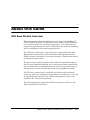
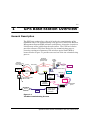
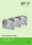
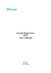
P/N 700-0043-001 OptiMesh™ Base Station Installation and User Guide Revision M-B1 Publication History Date Revision Description November 2000 M-A1 Initial Release January 2001 M-B0 Additions and Modifications to Procedures and Diagrams, Additions to Troubleshooting and Tips February 2001 M-B1 Modification of Procedure 6-3 (additional steps and screen captures) OptiMesh is a trademark of AirFiber, Inc. The following are trademarks or registered trademarks of their respective companies or organizations: SPARC, SPARCstation are trademarks of Sun Microsystems, Inc. HP OpenView is a trademark of Hewlett-Packard Company. UNIX is a trademark of The Open Group. Ashtech, Locus, and Geodetic Base Station Software (GBSS) are trademarks of the Magellan Corporation. Dell is a trademark of the Dell Computer Corporation. Intel is a trademark of the Intel Corporation. All other brand or product names are the trademarks or registered trademarks of their respective companies or organizations. Copyright 2000 AirFiber, Inc., All Rights Reserved The information contained in this document is the property of AirFiber, Inc., and is strictly confidential. By receipt of this manual, the recipient agrees that no part of this publication will be reproduced, stored in a retrieval system, or transmitted, in any form or by any means-electronic, mechanical, recording, or otherwise-without the prior written consent of AirFiber, Inc. The content of this document is subject to change without notice, and should not be construed as a commitment by AirFiber, Inc. AirFiber, Inc. assumes no responsibility or liability for any errors or inaccuracies that may appear in this document. OptiMesh Base Station Installation and User Guide M-B1 Table of Contents About this Guide . . . . . . . . . . . . . . . . . . . . . . . . . . . iii GPS Base Station Overview. . . . . . . . . . . . . . . . . . . . . . . . . . . . . . iii Safety Considerations. . . . . . . . . . . . . . . . . . . . . . . . . . . . . . . . . . iv Document Conventions. . . . . . . . . . . . . . . . . . . . . . . . . . . . . . . . . iv Notes . . . . . . . . . . . . . . . . . . . . . . . . . . . . . . . . . . . . . . . . . . . iv Customer Support . . . . . . . . . . . . . . . . . . . . . . . . . . . . . . . . . . . . vi GPS Base Station Overview. . . . . . . . . . . . . . . . . . 1-1 General Description . . . . . . . . . . . . . . . . . . . . . . . . . . . . . . . . . . 1-1 Hardware Components . . . . . . . . . . . . . . . . . . . . . . . . . . . . . . . . 1-4 Rooftop Antenna . . . . . . . . . . . . . GPS Receiver . . . . . . . . . . . . . . . . Serial Fiber-optic Converter Modem Environmentally-Hardened Receiver ........ ........ ........ Enclosure . . . . . . . . . . . . . . . . . . . . . . . . . . . . . . . . . . . . . . . . . . . . . . . . . . . . . 1-4 1-6 1-8 1-9 Optional Battery Box . . . . . . . . . . . . . . . . . . . . . . . . . . . . . . . . 1-11 Windows NT Workstation . . . . . . . . . . . . . . . . . . . . . . . . . . . . . 1-12 Software Components . . . . . . . . . . . . . . . . . . . . . . . . . . . . . . . 1-12 Geodetic Base Station Software Locus Processor Software . . . . Additional Utility Programs . . . Locus Survey Project Manager . System Requirements . . . . . . . (GBSS) ...... ...... ...... ...... . . . . . . . . . . . . . . . . . . . . . . . . . . . . . . . . . . . . . . . . . . . . . . . . . . . . . . . . . . . . . . . . . . . . . . . . . . . . . . . . . . . . . 1-13 1-13 1-13 1-13 1-14 GPS Base Station Parts Listing. . . . . . . . . . . . . . . . . . . . . . . . . . 1-14 OptiMesh Base Station Installation and User Guide M-B1 ii Site Preparation . . . . . . . . . . . . . . . . . . . . . . . . . . 2-1 Site Survey Data . . . . . . . . . . . . . . . . . . . . . . . . . . . . . . . . . . . . 2-1 Configuration Options. . . . . . . . . . . . . . . . . . . . . . . . . . . . . . . . . 2-2 Indoor Configuration . . . . . . . . . . . . . . . . . . . . . . . . . . . . . . . Outdoor Configuration. . . . . . . . . . . . . . . . . . . . . . . . . . . . . . . 2-2 2-5 Antenna Mount Options . . . . . . . . . . . . . . . . . . . . . . . . . . . . . . . 2-6 Mount Specifications . . . . . . . . . . . . . . . . . . . . . . . . . . . . . . . . 2-8 Safety Requirements . . . . . . . . . . . . . . . . . . . . . . . . . . . . . . . . . 2-8 Lightning Protection . . . . . . . . . . . . . . . . . . . . . . . . . . . . . . . . . . 2-9 Site Construction—Indoor Configuration . . . . . . . 3-1 Introduction . . . . . . . . . . . . . . . . . . . . . . . . . . . . . . . . . . . . . . . 3-1 Tools and Materials . . . . . . . . . . . . . . . . . . . . . . . . . . . . . . . . . . 3-2 Coaxial Cable Configuration . . . . . . . . . . . Coaxial and Fiber-optic Cable Configuration . Parapet Mount . . . . . . . . . . . . . . . . . . . . . Tripod Mount . . . . . . . . . . . . . . . . . . . . . . Coaxial Cable Installation . . . . . . . . . . . . . . . Fiber-optic Cable Installation Procedures . . . . . . . . . . . . . . . . . . . . . . . . . . . . . . . . . . . . . . . . . . . . . . . . . . . . . . . . . . . . . . . . . . . . . . . . . . . . . . . . . . . . . . . . . 3-2 . 3-3 . 3-3 . 3-3 . . 3-4 . 3-8 Site Construction—Outdoor Configuration . . . . . . 4-1 Introduction . . . . . . . . . . . . . . . . . . . . . . . . . . . . . . . . . . . . . . . 4-1 Tools and Materials . . . . . . . . . . . . . . . . . . . . . . . . . . . . . . . . . . 4-2 Parapet Mount . . . . . . . . . . . . . . . . . . . . . . . . . . . . . Tripod Mount . . . . . . . . . . . . . . . . . . . . . . . . . . . . . . Fiber-Optic Installation . . . . . . . . . . . . . . . . . . . . . . . . . Optional Battery Box Installation . . . . . . . . . . . . . . . . . Environmentally-hardened Receiver Enclosure Installation . . . . . . . . . . . . . . . . . . . . . . . . GPS Base Station Software Configuration . . . . . . Introduction . . . . . . 4-3 . 4-3 . 4-4 . 4-5 . 4-12 5-1 . . . . . . . . . . . . . . . . . . . . . . . . . . . . . . . . . . . . . . . 5-1 GBSS Software Configuration . . . . . . . . . . . . . . . . . . . . . . . . . . . 5-2 Tornado FTP Configuration . . . . . . . . . . . . . . . . . . . . . . . . . . . . . 5-6 OptiMesh Base Station Installation and User Guide M-B1 iii Cygnus BASH . . . . . . . . . . . . . . . . . . . . . . . . . . . . . . . . . . . . 5-7 Auto Windows Logon 5-9 Turn Off Device/Serial Mice Conflict 5-10 Locus Processor Software . . . . . . . . . . . . . . . . . . . . . . . . . . . . . RAS–Configuration of the PPP Dial-in through Base Station 5-10 . . . . . 5-11 Obtaining GPS Base Station Reference Data. . . . . 6-1 Introduction . . . . . . . . . . . . . . . . . . . . . . . . . . . . . . . . . . . . . . . 6-1 Considerations for Establishing Seed Values . . . . . . . . . Obtaining Seed Values Reference to Existing Remote Base Station . . . . . . . . . . . Obtaining Seed Values No Reference to Existing Remote Base Station . . . . . . . . . Obtaining Seed Values No Reference to Existing Remote Base Station (monument) ...... 6-1 ...... 6-3 ...... 6-6 ...... 6-8 Base Station Operation . . . . . . . . . . . . . . . . . . . . . 7-1 Maintenance . . . . . . . . . . . . . . . . . . . . . . . . . . . . . 8-1 Alternating Current Power. . . . . . . . . . . . . . . . . . . . . . . . . . . . . . 8-1 Checking Fiber-Optic Cable . . . . . . . . . . . . . . . . . . . . . . . . . . . . . 8-1 Visual Inspection . . . . . . . . . . . . . . . . . . . . . . . . . . . . . . . . . . . . 8-1 Direct Current Power/Battery . . . . . . . . . . . . . . . . . . . . . . . . . . . 8-1 Battery Specifications .............................. Maintaining The Battery Box ........................... 8-2 8-3 Removing the Batteries From The Battery Box . . . . . . . . . . . . . . . 8-4 Inserting and Connecting the Batteries . . . . . . . . . . . . . . . . . . . . . 8-5 Troubleshooting . . . . . . . . . . . . . . . . . . . . . . . . . . Problem Resolution . . . . . . . . . . . . . . . . . . . . . . . . . . . . . . . . . . OptiMesh Base Station Installation and User Guide 9-1 9-1 M-B1 iv OptiMesh Base Station Installation and User Guide M-B1 v About this Guide GPS Base Station Overview This document describes the installation and setup of the OptiMesh™ Global Positioning System (GPS) base station, used to obtain GPS reference data during the site commissioning process. It is written for site engineering and construction staff or individuals who will be performing the site installation and commissioning function. The GPS base station plays a key role in site commissioning the OptiMesh nodes, the process by which the Element Management System (EMS) software establishes a connection (acquires a link between nodes) and brings the node online. The base station is fixed equipment that remains installed throughout the life of the OptiMesh network, but is only required when commissioning a new node into an OptiMesh network. It is not required during normal operation of either an individual node or the OptiMesh network. The GPS base station must be installed and reference data obtained before any other site commissioning procedures can take place. For additional information about the site commissioning process, refer to the OptiMesh Site Commissioning Guide. The following diagram depicts the GPS base station in relation to the Link Acquisition System (LAS): OptMesh Base Station Installation and User Guide M-B1 vi Link Acquisition System (LAS) GPS Base Station (GBS) Link Acquisition Kit (LAK) Link Acquisition Fixtures (LAFs) Link Acquisition Briefcase (LAB) Link Acquisition Program (LAP) Figure i-1 The Link Acquisition System Safety Considerations The following safety precautions apply to the use of the GPS base station. DANGER If the configuration you are using to install the GPS base station consists of coaxial cable connecting to the GPS receiver located inside of the building, in-line lightning surge protection (provided in the base station installation kit) must be installed. Ensure that the surge suppressor is connected to the building ground. Document Conventions The following conventions are used throughout this manual. Notes Notes are accompanied by an icon that indicates the type of note. OptiMesh Base Station Installation and User Guide M-B1 vii Informational Note INFORMATION The icon shown to the left denotes an informational note relating to the topic being discussed in that section of the document Cautionary Note CAUTION The icon shown to the left denotes a cautionary note. A cautionary note provides information that is essential to preventing damage to the OptiMesh equipment or other equipment described in the note. Warning Note DANGER The icon shown to the left denotes a warning note. A warning note provides information that is essential to preventing harm to individuals who are installing or operating the product. Tip TIP The icon shown to the left identifies a tip or technique that is helpful to the topic being discussed. OptiMesh Base Station Installation and User Guide M-B1 viii Text Conventions User Action In instructions, when you are required to select an option, the option appears with the first letter of the word capitalized. For example: From the computer’s desktop, click on the Start button. Information you are required to enter appears in a different font: courier new 10, bold. For example: Type: C:\Ashtech Information that the system displays appears in courier new 10. For example: The system returns the message: Disconnect the tiltmeter. Customer Support Contact AirFiber’s Customer Support department at 858.676.7001 or toll-free at 877.576.7001, or send email to [email protected]. You can also contact Customer Support through the AirFiber website: www.airfiber.com. OptiMesh Base Station Installation and User Guide M-B1 1-1 11- GPS Base Station Overview General Description The GPS base station plays a key role in the site commissioning of the OptiMesh nodes. Site commissioning is the process by which the Element Management System (EMS) software establishes a connection (acquires a link between nodes) and brings the node online. The GPS base station provides reference GPS data during the site commissioning process, ensuring centimeter alignment of the wireless optical links (WOLs) between nodes. Figure 1-1 provides an overview of the site commissioning process. Previously commissioned premise node Alternate: Direct home run to the switch ATM switch Router Root node Newly installed node Infrared transmit Infrared receive In-band communication link Step 1 Link Acquisition Fixture ADM Fiber-optic SONET/SDH ring Ethernet ADM Base station antenna User interface at the NOC the EMS Node connection box Base station receiver/ workstation Internet Step 4 Step 3 Laptop PC Internal corporate intranet or cell/ satellite phone connection Step 2 Cell/satellite phone Wireless or LAN modem Figure 1-1 The Site Commissioning Process OptiMesh Base Station Installation and User Guide M-B1 1-2 Table 1-1 Site Commissioning Process Detail Steps Sequence Description Step 1 Under LAP control and using the LAF, measure the node position (x.y.z, tip, tilt, orientation). Store this information on the laptop PC. Step 2 Collect reference position data from the base station and download to the laptop PC. Step 3 Laptop PC computes the precise node position (centimeter accuracy) from data obtained in steps 1 and 2 above. Step 4 Laptop PC transfers the precise node location to the EMS. The EMS then: computes the turret pointing vectors, downloads the pointing vectors to the laptop PC, and requests that the newly installed node align its turrets to those of its partner nodes. The GPS base station is used only for site commissioning; it is not required for ongoing operation of the OptiMesh network. However, because the GPS base station provides reference position data for the nodes in the OptiMesh network, it is installed permanently for future commissioning of OptiMesh nodes, or to recommission a node if necessary. If the OptiMesh network is configured so that no one base station can be located within 12.4 mi (20 km) of each node in the network, additional GPS base stations are required to provide reference data for the site commissioning process. These additional base stations will use positioning data from the original base station to determine a reference position. This methodology ensures that all position measurements in the entire OptiMesh network are in reference to one position—the first base station installed. Specific instructions on how to collect this data are provided in Chapter 6, Obtaining GPS Base Station Reference Data. The GPS base station consists of the following components: • A rooftop-mounted antenna that can be located up to 12.4 miles (20 km) from the farthest node in the AirFiber OptiMesh network • A GPS receiver that processes signals from the GPS satellite constellation to provide real-time position, velocity, and time measurements used to generate reference position of the GPS base station • A Windows NT Workstation running the following software packages: Geodetic Base Station Software (GBSS) Locus GPS and GPS Base Station Software (LGPS–GBSS) OptiMesh Base Station Installation and User Guide M-B1 1-3 Various Utility Programs: (Cygnus BASH, PKZIP, Tornado FTP daemon, TweakUI) Ashtech Locus Survey Project Manager Software • A coaxial cable connecting the antenna to the GPS receiver, and associated surge protection equipment. • An optional customer supplied fiber-optic cable to connect the GPS receiver to the NT workstation, used when the distance between the antenna and the GPS receiver is greater than 500 ft (152.4 m), or when the receiver is located outside on the rooftop. • Optional serial fiber converter modem(s) used when a fiber-optic cable is used to connect the GPS receiver to the NT workstation. • An optional environmentally hardened receiver enclosure containing the GPS receiver and a serial fiber converter modem in the case of an outdoor configuration. • A DB25 to DB9 cable for connecting the GPS receiver to the serial port of the Windows NT workstation. The antenna, standing atop one or two four-foot pipes (maximum height of the pipes is 8 ft [2.4 m]), is mounted on the roof of the building so that the antenna has an unobstructed view of the sky for satellite tracking. A wall mount or non-penetrating tripod can be used to anchor the antenna to the building rooftop. Next, the antenna is connected to the GPS receiver, which in turn is connected to a Windows NT workstation running the GPS base station software programs designed to collect and process reference data. Attachment to the NT workstation is accomplished with a standard RS-232 serial port, and to a standard power outlet for power with a power transformer. There are three main configuration choices for connecting the components of the GPS base station assembly. INFORMATION The key factors that determine which choice is appropriate for your installation are the distance from the antenna to the GPS receiver, the distance from the antenna to the NT workstation and the physical characteristics of the site. If the building layout prohibits the location of the GPS receiver within 500 ft (152.4 m) of the antenna, then an outdoor configuration should be used. Please see Table 1-2, and Configuration Options in Chapter 2 for additional information about the configurations. OptiMesh Base Station Installation and User Guide M-B1 1-4 Table 1-2 Configuration Options Distance Characteristics Configuration Distance from antenna to NT Indoor, coaxial cable option workstation less than 500 ft (152.4 m) Distance from the antenna to GPS Indoor, coaxial cable and fiber receiver less than 500 ft (152.4 m), option and distance from GPS receiver to NT workstation greater than supported by the RS-232 serial cable Distance from the antenna to the GPS receiver greater than 500 ft (152.4 m) if GPS receiver were to be housed inside the building Outdoor, coaxial cable and fiber option, use of environmentally hardened box to house GPS receiver outside. Hardware Components Rooftop Antenna The antenna is mounted on the rooftop and can be located up to 12.43 miles (20 km) from the farthest node in the OptiMesh network. The antenna must have a clear view of the sky without any obstructions, and should be located away from potential EMI interference. There are two different types of mounts available for the antenna: • Parapet: Antenna is mounted on one or two 4 ft poles, and attached to the wall with mounting brackets. Figure 1-2 provides an example of the GPS base station using a parapet mount. OptiMesh Base Station Installation and User Guide M-B1 1-5 Antenna Coaxial cable (up to 500 ft/152.4 m) Mounting bracket 4-ft (1.22-m) pipes for mounting antenna In-line lightning surge protection Roof GPS receiver Serial G12 GPS AC-DC "wall cube" Computer Computer Customer-provided optional UPS Figure 1-2 GPS Base Station using a Parapet Mount • Non-penetrating Tripod: A 4 ft (1.2 m), 6 ft (1.8 m), or 8 ft (2.4 m) pole is inserted in the tripod base. The antenna is mounted on a pole, and attached to the tripod pole by means of two clamps. The tripod is anchored to the roof by means of concrete cinderblocks. As an alternative, you may choose to anchor the tripod in a permanent manner (for example, using bolts) according to your building conditions and requirements. Figure 1-3 provides an example of the GPS base station with a non-penetrating tripod mount. OptiMesh Base Station Installation and User Guide M-B1 1-6 Antenna Coax 4ft (1.2 m), 6 ft (1.8 m), or 8 ft (2.4 m) pole In-line lightning surge protection Tripod stand Roof Serial GPS GPS receiver AC-DC - "wall cube" NT Computer Workstation Customer-provided optional UPS Figure 1-3 GPS Base Station with Tripod Mount GPS Receiver The GPS receiver processes signals from the GPS satellite constellation to provide real-time position, velocity, and time measurements. It uses 12 dedicated separate and parallel channels for Coarse/Acquisition (C/A) code-phase (pseudo-range) and carrier-phase measurement on the L1 (1575.4 MHz) band. The GPS receiver receives satellite signals via an L-band antenna and low-noise amplifier (LNA). Operation Within 6 seconds after the first satellite (Space Vehicle or SV) lock, the GPS receiver time is set. If no ephemeris data are in memory, or if the data are older than 10 hours, 30 to 60 seconds are needed to collect data. After three or four SVs are locked and the almanac/ephemeris data is collected, the GPS receiver computes its first position. At the next power up, OptiMesh Base Station Installation and User Guide M-B1 1-7 if the data has been backed up and is less than 10 hours old, the GPS receiver uses it to search only visible SVs. Under these conditions, the GPS receiver recomputes position in 10 to 12 seconds. The GPS can track all Block I and Block II GPS satellites. All thirty-two PseudoRandom Noise (PRN) numbers (as specified in Navstar GPS Space Segment/Navigation User Interfaces, ICD-GPS-200, Revision B) are coded inside the receiver/processor card. The GPS constellation comprises twenty-four SVs. As it acquires each SV, the GPS receiver notes the time and collects the ephemeris data about the orbit of that SV, and almanac data about the orbits of all the SVs in the constellation. To compute three-dimensional position and velocity, the GPS receiver needs to lock on to at least four SVs. Up to 20 independent measurements are determined per cycle, with no interpolation or extrapolation from previous solutions. Light-Emitting Diodes The GPS receiver has a two-color light-emitting diode (LED); red indicates the power status, and green indicates the number of SVs locked. As an example, four green flashes indicate four satellites are locked. On power-up, the status LED lights red and then continues to flash red indicating that the unit is on and there is no position computed. When the GPS automatic search results in an SV acquisition, the status LED flashes green between the red power status flashes. Every SV lock-on produces a green flash, where a short green flash indicates the satellite is locked but not being used; a medium-duration green flash means the SV is locked but ephemeris for that satellite has not yet been collected; and a long green flash indicates that ephemeris for that satellite is available. Once the unit is locked to enough satellites to compute a position, the red flash is longer, indicating it is computing a position. Table 1-2 provides a quick reference to LED status operations. OptiMesh Base Station Installation and User Guide M-B1 1-8 Table 1-3 GPS Receiver LED Quick Reference LED Function Color (green/red alternate in the LED) Satellite Tracking and Power Status Red/Short Flash Unit on, no position computed yet. Green/Short Flash Satellite locked but not being used. Green/Medium Flash Satellite locked, and data is being collected. Green/Long Flash Satellite locked, enough positioning data has been collected Red/Long Flash Receiver has tracked and collected enough data from the satellites, and is computing a position. Power Requirements The GPS receiver requires a direct current input voltage of 5 V dc (regulated ± 5%) and consumes approximately 1.4 W of power. The GPS receiver is capable of 110 V/60 Hz or 220 V/50 Hz operation. A power adapter is supplied in the GPS base station kit. Serial Fiber-optic Converter Modem The serial fiber-optic converter modem is designed to draw power from the power jack only and consumes very low power. The input direct current voltage is from 9 V to 14 V and current is @300 mA. The connector is a terminal block type with polarity indicated on the top cover of the unit. If the external power adapter need to be replaced, use one with the following specifications: 12 V dc @800 mA. The modem is capable of 110 V/60 Hz or 220V /50 Hz operation. OptiMesh Base Station Installation and User Guide M-B1 1-9 Figure 1-4 Serial Fiber-optic Converter Modem Environmentally-Hardened Receiver Enclosure The environmentally-hardened receiver enclosure is used to house the GPS receiver in the event the receiver needs to be located outside on the rooftop (outdoor configuration). The enclosure contains the: • GPS receiver • Serial fiber-optic converter modem • Alternating current/direct current power supply • AirFiber direct current/direct current board • Heater • Heater controller OptiMesh Base Station Installation and User Guide M-B1 1-10 Figure 1-5 Environmentally-hardened Receiver Enclosure The enclosure is capable of accepting 93 to 132 V ac and 187 to 264 V ac. The power supply automatically adjusts according to the input voltage range. The power supply operates over a 47 to 63 Hz power input frequency range, and a –40°C to +70°C temperature range. The enclosure will draw approximately 50 W with the heater operating (during low temperature situations) and 5 W without the heater. Table 1-4 Environmentally-hardened Receiver Enclosure Physical Characteristics Characteristic Comment Weight Measurement 27.6 lb (12.519 kg) Size Height x width x depth 20 x 15.6 x 8.4 in. (50.80 x 39.62 x 21.34 cm) Power Without heater 15 W With node heater and connector box heater 105 W 120 V ac nominal 104 V ac to 127 V ac, 60 +/-3 Hz 240 V ac nominal 208 V ac to 254 V ac, 50 +/- 3 Hz Primary Input Voltage OptiMesh Base Station Installation and User Guide M-B1 1-11 Optional Battery Box The battery box can be used as an alternative or backup power source for the environmentally-hardened outdoor receiver enclosure used in the outdoor configuration. Table 1-5 Battery Box Physical Characteristics Characteristic Weight Size Comment Measurement Without batteries 33.2 lb (15.060 kg) With batteries 85.6 lb (38.83 kg) Height x width x depth 24 x 15.6 x 13 in. (60.96 x 39.62 x 33.02 cm) Power Without heater 1W With heater 45 W Table 1-6 Battery Physical Characteristics Characteristic Comment Measurement Length 7.13 in. (18.11 cm) maximum Width 3 in. (7.62 cm) maximum Height 6.59 in. (16.74 cm) maximum Approximate Weight 13.10 lbs (5.94 kg) Terminals Faston Quick Disconnect Tabs Case ABS Plastic 0.250 x 0.032 in. (0.635 x 0.0813 cm) Table 1-7 Battery Electrical Characteristics Characteristic Battery type Comment Measurement Sealed Lead Acid Rechargeable Nominal voltage (per battery) 12 V (six cells in series) *Nominal capacity (per battery) Operating temperature range 20 hour rate 18 ampere-hours -40°C to +60°C OptiMesh Base Station Installation and User Guide M-B1 1-12 Table 1-7 Battery Electrical Characteristics Charging temperature range Charge voltage provided -20°C to +40°C Four batteries in float mode Charge current provided 54.0 V dc to 55.0 V dc (54.4 V dc nominal) 750 mA maximum *Capacity can vary based on customer requirements Additional Notes: Note 1: To minimize the effects of individual battery differences, which detrimentally affect recharging, all four batteries should be of the same age, storage history, and usage. All batteries must be replaced at the same time. Note 2: Battery discharging is limited to 42 V across 4 batteries (10.5 V dc per battery). Note 3: Recharging is disconnected above +37°C. Windows NT Workstation The Windows NT workstation is shipped as part of the GPS base station package. The specific configuration is designed for optimal performance and maintenance of the GPS base station. The workstation is shipped with the software installed on the system. The NT workstation is a customized Dell workstation that includes the following components: • Intel Celeron processor with Intel 810 chipset 64 Mbyte SDRAM memory Enhanced IDE 7 Gbyte hard drive CD-ROM Drive and 3.5-in. floppy drive • Dell E550 15 in. monitor • Quietkey keyboard • Two-button PS/2 Mouse • Internal modem and cable for connectivity to the LAK laptop Software Components The Windows NT workstation that is shipped with the GPS base station is installed with all the software that is needed to establish the GPS base station reference data. Certain software parameters do need to be configured to enable the GPS base station to effectively communicate during OptiMesh Base Station Installation and User Guide M-B1 1-13 the link acquisition process, and to properly collect GPS base station positioning data. In the event the software needs to be reinstalled, please refer to the installation notes in Chapter 8, Troubleshooting. Geodetic Base Station Software (GBSS) The GBSS software is a Windows NT and 2000 program specifically designed for continuous logging of high-quality GPS data. After a period of writing to a file, the file is closed and a new one is opened. This length of time is 1 hour by default, but can be made longer. In practice, there is approximately a 5 second delay between one file closing and the next one opening, which will invalidate measurements made across that delay. As part of the software licensing requirements, the GBSS software requires a hardware key—a “dongle”—be attached to the NT workstation’s parallel port in order to run. The dongle is provided with the NT workstation. CAUTION Safeguard the GBSS software dongle. Replacing a lost hardware dongle/key requires the purchase of an additional software license; please ensure the hardware dongle/key is kept securely on the NT workstation at all times. Locus Processor Software The Locus Processor software is AirFiber software that performs the timing association between data collected at the remote node and the data collected at the base station. Additional Utility Programs Cygnus BASH, PKZIP, Tornado FTP daemon, TweakUI, perform various utilities in the site commissioning process. Locus Survey Project Manager The Locus Survey Project Manager software computes the base station’s position data. This is used for determining the “seed” value or reference value of the base station position for the entire OptiMesh network. Instructions for obtaining reference data are provided in Chapter 6, Obtaining GPS Base Station Reference Data. OptiMesh Base Station Installation and User Guide M-B1 1-14 System Requirements The GPS base station software is designed for use on a Windows NT 4.0 system. The NT workstation is shipped as part of the GPS base station package. In the event the workstation needs to be replaced, please contact AirFiber customer support for information about system requirements for the NT workstation. GPS Base Station Parts Listing All the components needed for the GPS base station assembly will be provided in the packaging sent to your site, with the exception of some standard tools listed in Chapter Two, Tools and Materials. INFORMATION The component list will vary, depending upon the configuration selected for your site. For those sites using the Indoor Configuration, the necessary crimp tools and connectors will be provided. The parts used for all GPS base station configurations are listed below. Verify shipped components against the items in this list identified for your configuration, and if replacement parts are required, use this list to identify needed components. Note: Excess hardware may be included as spares. Table 1-8 GPS Base Station Parts AirFiber Part Number Qty Used Description 395-0031-001 1 GBS indoor receiver 072-0051-000 1 GBS antenna 072-0050-000 1 Coaxial cable—33 ft (10 m) with connectors (outdoor configuration) 072-0036-000 1 Coaxial cable—500 ft (152.4 m) with connectors (indoor configuration) 072-0016-000 1* Modem, fiber-optic, RS232, async, high temp (serial fiber-optic converter modem) (indoor coaxial and fiber option, and outdoor configurations) OptiMesh Base Station Installation and User Guide M-B1 1-15 AirFiber Part Number Qty Used Description 300-0017-002 1 AirFiber outdoor receiver enclosure (environmentally hardened receiver enclosure) (outdoor configuration) 072-0035-000 1 Surge protector, coax in-line, GPS (indoor configurations) 072-0038-000 0-5** Connector, N-type, Male 072-0039-000 1 Tool, crimp (0.429 hex) 072-0040-000 1 Tool, cable prep, LMR-400 700-0043-001 1 GBS User Manual (CD-ROM) or AirFiber Web site 300-0016-002 1 GBS battery assembly enclosure*** (outdoor configuration, optional) 022-0017-000 1 Batteries*** (outdoor configuration, optional) 072-0044-000 1 Computer, GPS base station 101-0089-001 1 RS-232 cable 395-0032-001 1 Parapet mount (wall, corner and penthouse) 395-0033-001 1 Tripod mount Note: *Two serial fiber-optic converter modems will be provided for the indoor configuration, fiber-optic option. For the outdoor configuration, the 2nd fiber-optic converter modem is included in the outdoor receiver enclosure. Note: **Five connectors will be shipped for both indoor configurations; four are used at each end of the cable attachment and one is a spare. Note: ***Please note that the battery backup unit is optional, and is applicable only to the outdoor configuration. Please see Configuration Options in Chapter Two for additional information about the indoor and outdoor configurations. OptiMesh Base Station Installation and User Guide M-B1 1-16 INFORMATION For documentation and software updates, please visit www.airfiber.com. OptiMesh Base Station Installation and User Guide M-B1