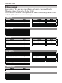
1
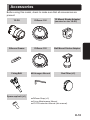
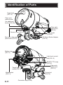
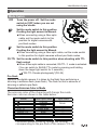
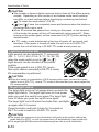
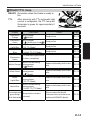
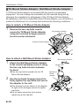
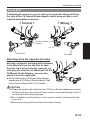
03117 03118 UNDERWATER STROBE 日本語 YS-D2 English 取扱説明書 Instruction Manual Introduction Thank you for purchasing SEA&SEA products. Please read this instruction manual carefully prior to using your underwater strobe. Only with a thorough understanding of this manual's content will you be able to use the strobe correctly. After reading the manual, please be sure to keep it in a place where you can easily come back to it at any time. Note: This products have passed SEA&SEA’s criteria-based inspection for pressure resistance. This device complies with Part 15 of the FCC Rules. Operation is subject to the following two conditions: (1) this device may not cause harmful interference, (2) this device must accept any interference received, including interference that cause undesired operation. The product conforms to WEEE standards. This symbol indicates separate collection of waste electrical and electronic equipment in the EU countries. Please do not throw the equipment into the domestic refuse. Please contact your local authorities for recycling program information. The appearance of color evenness or weld lines on the external body of the product is normal and will not affect its performance. This Class B digital apparatus complies with Canadian ICES-003. CAN ICES-3(B)/NMB-3(B) E-1 Contents Safety Precautions ................................................................................. E-3 Safety Precautions for Use of Battery .................................................... E-6 Precautions on Handling the O-ring ....................................................... E-8 Accessories ......................................................................................... E-10 Identification of Parts ..................................................................... E-11 Operation ....................................................................................... E-12 READY/TTL lamp .......................................................................... E-13 YS Mount Strobe Adaptor/Ball Mount Strobe Adaptor.................... E-14 Preparation for Setting Up ................................................................... E-17 Installing the Batteries ......................................................................... E-17 Connecting the Strobe ........................................................................ E-19 With the Sync Cord ....................................................................... E-19 With the Fiber-optic Cable ............................................................. E-21 Taking Photographs ............................................................................. E-23 Using the Sync Cord ..................................................................... E-23 Using the Fiber-optic Cable .......................................................... E-24 Using the Diffuser ......................................................................... E-26 Using the Red Filter....................................................................... E-27 Customize Mode.............................................................................. E-28 Maintenance and Storage .................................................................... E-30 Troubleshooting ................................................................................... E-31 Specification ........................................................................................ E-32 Safety Precautions SEA&SEA strobes have been designed for in-water use only. Limit the strobes use out of water to test firing only. For safe handling of the product, please read the following precautions carefully before use. Failure to heed the precautions listed below could result in serious consequences. To prevent injury or damage to yourself and/or others, please observe the precautions as they contain highly important information related to personal and product safety. DANGER Situations that involve a high risk of severe injury or death. WARNING Situations that could result in severe injury or death. CAUTION Situations that could result in property damage or personal injury. DANGER Never attempt to disassemble, repair or alter the product yourself to prevent significant electrical hazard due to the high-voltage circuitry in the product. Do not heat the product or put it into a fire, this could result in explosion or fire. Unauthorized disassembling and/or modification could result in malfunction or flooding, and void product warranty. Take the product to a SEA&SEA authorized service center for repair or inspection. WARNING Use only batteries approved for use in this product. Do not mix old and new batteries of different types. Remove batteries before transport or storage, or when you are not going to use the product for an extended period of time, to prevent unexpected activation. Pay particular attention to opening the battery cap to avoid injury. Heat from the batteries may cause pressure buildup inside the battery compartment, and could result in cap explosion with unexpected force. Prevent water or foreign objects from entering the product. Discontinue use and turn it off immediately should you notice flooding or leakage. Continuous use could result in complete damage to the product. Do not handle batteries with wet hands to prevent shock hazards. Do not use the product in the presence of flammable gas, as this could result in explosion or fire. Do not fire the strobe/light with the reflector facing a desk or floor to prevent a fire from occurring. Touching the reflector immediately after firing could result in burns. E-3 Safety Precautions Do not fire the strobe light towards a driver of a vehicle to avoid causing accidents. Do not operate the product while driving a vehicle. Inattention could result in accidents. For use on land, do not operate the product at precarious foothold. It may cause falling, injury or product damage. Do not leave the product on a slope or an unstable surface. It may be broken after falling or injure someone below it. Keep out of reach of children to prevent accidental ingestion. If swallowed, seek medical advice immediately. CAUTION Read the instruction manual and observe proper precautions before use of this product. This product has been designed and manufactured for use at a water depth within 100m / 330ft. Please note that diving to a depth in excess of 100m / 330ft may cause damage to the product or may lead to water leakage. Should you notice smoke or unusual smell coming from the product, turn it off and remove the batteries immediately, taking care to avoid burns. Continued operation could result in injury. After removing the battery, take the product to a SEA&SEA authorized service center for inspection. Discontinue use and turn the product off immediately should you notice flooding or leakage. When the product is flooded, interior pressure may build up. Please be careful the cap may open explosively and cause injuries. Do not open the battery cap in the vicinity of open flames. The product has been constructed with an airtight seal. When packing the product for airplane travel, Please be transported Remove the battery cap. Do not open the product in a wet or sandy environment. Protect the interior from moisture and debris in order to prevent malfunction or flooding. Keep away from strong magnetic fields. Do not use or store this product in the vicinity of equipment that generates strong electro-magnetic radiation or magnetic fields. Strong static charges or the magnetic fields could cause malfunction, or affect the product's internal circuitry. Before using the product in an airplane or a hospital, check if it is allowed. Electromagnetic waves emitted by the product may interfere with the measuring instruments or medical equipment. Do not cover or wrap the product with a cloth when firing the strobe. This could result in deformation of the product or in fire. Using the strobe close to your subject's eyes could cause temporary visual impairment. Particular care should be observed if photographing infants, the strobe should be no less than one meter (3 feet) from the subject. Safety Precautions Be careful when touching the product immediately after firing repeatedly or lighting for a long time. The product may get hot enough to burn you. Avoid strong shocks / impacts or excess stress to prevent malfunction, damage or breakdown. Make sure that the product has been securely mounted to other products in order to prevent injury, fall or missing. Do not carry the camera or housing by holding the accessories such as arm, cable, strobe, etc. Heavy components may fall and cause damage or injury. Do not rest heavy weight on the product. It might deform the outer casing, damage internal parts, make the waterproofing fail, or result in fire or electric shock. Rinse the product with fresh water, after underwater use. Ensure that the product is watertight before rinsing. Refer to [Maintenance and Storage] for details. Make sure that the connectors have been secured with the connector caps before rinsing the product with fresh water, after removal from other products. Never use chemicals, cosmetics, any petroleum solvents such as paint thinner, or neutral detergent on the product. They may deform and damage the product. Do not leave the product in places with hot temperatures such as inside of a car or in a car trunk in summer. The heat may deform plastic parts of the product, damaging internal parts and resulting in potential fire or electric shock. If the product is sealed tight in hot conditions, heated air expanding inside the product may deform the casing and ruin the watertightness. Do not store the product in wet or high humidity place, to avoid mold, rust, corrosion or malfunction. Do not store the product with naphthalene or camphor mothballs, or in locations such as a laboratory where chemicals are used. This environment can cause mold, rust, corrosion or malfunction. If you do not use the product for an extended period of time, periodic maintenance will keep internal electronic parts from deterioration. Once a month, install batteries and fire a test flash / light on. Operate all other switches as you would in normal operation. Turn the power off, then remove batteries while the READY/TTL lamp is on for the strobe. SEA&SEA SUNPAK Co., Ltd. assumes no liability for compensation of loss of captured images or expenses caused by loss of images, even if you are unable to shoot due to a product defect or malfunction. SEA&SEA SUNPAK Co., Ltd. will not be responsible for the replacement or compensation for cameras, lenses or those accessories damaged due to your invalid operation. Carefully observe the O-ring maintenance manual for the handling of O-rings before use. SEA&SEA SUNPAK Co., Ltd. assumes no liability for errors or discrepancies in this manual. Specifications and appearance are subject to change without notice. The silicon grease included in the product package is inedible. E-5 DANGER Never expose the battery to flame or fire, or to excessive heat. Never attempt to disassemble, alter or directly solder the battery. There are no user-serviceable parts. Tampering with battery may expose you to dangerous voltage, battery acid, or electrical shock. Never short-circuit the terminals of a battery, as it could result in battery leakage, heat generation, fire, or explosion. Avoid contact with all metal objects during transporting and storage. When recharging batteries such as nickel metal-hydride, use a charger designed specifically for them and follow the recharging instructions. Recharging with an inappropriate charger may cause battery leakage, overheating, and explosion. Move leaking batteries away from fire or open flames immediately. The leaked fluid and its vapor are combustible. If the battery leakage contacts your skin or clothing, flush the affected area repeatedly with clean water. It may irritate your skin. Should it get into your eyes, immediately rinse them with plenty of water, avoid rubbing and seek medical advice. Battery has a specific polarity. Never force the battery into the charger or the strobe.Always check the +and -polarity before installation. Incorrect orientation may cause permanent battery damage. Never connect a battery directly to a plug outlet or car cigarette lighter. WARNING Keep dry. The battery is not waterproof, and may malfunction if immersed in water or exposed to high levels of humidity. Rusting of the internal mechanism can cause irreparable damage. Do not remove and/or damage the case of a battery. It may cause battery leakage, overheating or explosion. Do not charge a rechargeable battery beyond the specified charging time, it may cause battery leakage, fire hazard or explosion. Never use batteries should you notice any changes such as leakage, discoloration or deformation. When you notice the situation as abnormal, discontinue use immediately and take the product to a SEA&SEA authorized service center for inspection. Keep out of reach of children to prevent accidental ingestion. If swallowed, seek medical advice immediately. Do not leave or use batteries in an extreme hot environment. This may cause battery leakage, overheating or battery performance deterioration. Do not use non-recommended batteries (such as lithium primary batteries). Use of non-recommended batteries may cause battery leakage and overheating and may cause the strobe to rupture,which could result in personal injury. Safety Precautions for Use of Battery CAUTION Avoid strong shocks / impacts or excess stress to batteries. For handling and recharging of a battery, refer to the instruction manual of the battery/dedicated charger. Always recharge the rechargeable battery before use after an extended time of storage. Dirt on the battery terminals can prevent the product from functioning. Should the battery terminals become dirty, wipe them with a clean, dry cloth before use. Used rechargeable batteries are valuable resource. Please recycle used rechargeable batteries in accordance with local regulations. E-7 Precautions on Handling the O-ring This product is kept watertight by the O-ring. To keep the O-ring functioning properly, please observe the following. Improper handling of the O-ring could cause flooding. CAUTION SEA&SEA products use blue O-rings. These O-rings are impregnated with silicone oil through a special process. The lubricating effect of the O-ring lasts as long as the silicone oil is gradually seeping out from within. For the maintenance of these blue O-rings, make sure to use genuine SEA&SEA silicone grease (O-ring grease for use with the blue O-rings that comes in tubes with blue lettering and blue caps). If you use silicone grease from other companies or SEA&SEA’s own silicone grease that comes in tubes with black lettering and black caps, the grease you apply will be sucked into the blue O-rings due to their special characteristics, which will result in insufficient grease. If this happens even once, the O-ring will not revert to its normal state and must be replaced. If the grease is insufficient, the O-ring will not slide, and it will become harder to open and close the waterproof parts. Because of this, it could become impossible to open or close the housing or it could cause flooding, so please refrain from using the housing with insufficient grease. Are there any scratches or cracks in the O-ring? Check the O-ring to make sure there are no scratches or cracks. If there are, replace the O-ring with a new one immediately. When handling the O-ring, do not use pointed metal objects, which could damage the O-ring. Be careful about dust, sand, and hair Check the O-ring to make sure that there is no dust, sand, or hair on the O-ring, in the O-ring’s grooves, or on the O-ring’s contact surfaces. If any of these things are attached, remove them completely. If used as is, these things could cause flooding. Precautions on Handling the O-ring Coat with silicone grease Silicone grease protects the O-ring from chafing. After checking the O-ring to make sure that there are no scratches, dust, or debris, apply a light coating of silicone grease to the entire O-ring with your finger. Applying too much grease will make it easier for dust and debris to adhere to the O-ring, and could cause flooding. Do not twist the O-ring When fitting the O-ring into the O-ring groove, insert it straight into the groove; do not bend or twist it. Remove the O-ring for inspection before each use In principle, the O-ring should be removed before each use so that the O-ring, O-ring groove, and O-ring contact surfaces can be checked. This is because you cannot find any sand or debris that may have gotten into the O-ring groove if the O-ring is not removed. For routine maintenance prior to each use, it is advisable to make sure to remove the O-ring. Be careful about how you store O-rings When storing spare O-rings or O-rings that you have removed from the housing, keep them in a cool place out of direct sunlight. Also, when storing O-rings, do not place heavy objects on them or twist them. O-rings last for one year Although it depends on how well they are maintained, how often they are used, and how they are stored, O-rings generally last for one year. It is advisable to inspect them before use, and replace them early. E-9 Accessories Before using this model, check to make sure that all accessories are present. YS-D2 Diffuser-100 YS Mount Strobe Adaptor (mounted on the YS-D2) 100 Silicone Grease Diffuser-120 Ball Mount Strobe Adaptor 120 Fixing Bolt Spare cap bolt (×1) M4 Hexagon Wrench Red Filter (×2) Diffuser Strap (×2) O-ring Maintenance Manual YS-D2 Instruction Manual (this manual) E-10 Identification of Parts Target light (P.E-13) Fiber-optic cable socket (for additional strobe (P.E-22)) Fiber-optic cable hook (P.E-21) Sensor cover (P.E-21) Strap eyelet (P.E-26) YS Mount Strobe Adaptor (P.E-15) Fiber-optic cable socket (Slave sensor (P.E-21)) Battery cap (P.E-17) Light level control dial (P.E-13) Target light switch (P.E-13) Mode switch (P.E-13) E-11 READY/ TTL lamp (P.E-14) Fiber-optic cable hook (P.E-21) Fixing bolt (P.E-16) Connector cap(P.E-20) Identification of parts Operation Mode Switch OFF M M Turns the power off. Set the mode switch to [OFF] when you are not using the strobe. Set the mode switch to this position if setting the light amount to Manual. When connecting using a fiber-optic cable, set the mode switch to this position for digital cameras with pre-flash modes. Set the mode switch to this position if setting the light amount to Manual. When connecting using a fiber-optic cable, set the mode switch to this position for digital cameras without pre-flash modes. DS-TTL Set the mode switch to this position when shooting with TTL flash output When a fiber-optic cable is connected, DS-TTL Ⅱ mode is activated. (You can switch to SLAVE-TTL mode by pressing and holding down the target light switch for 3 seconds.) “DS-TTLⅡmode photography”(P.E-24) Pre-flash Some of the digital camera, it is taken by the flash from performing a dimming in advance flash (main flash). The flash for this in advance of dimming is called a pre-flash. Characters Emission Color in Mode The emission color of the character will change the mode. Emission color are shown in the table below. Mode M M DS-TTL SLAVE-TTL TTL Customize Fiber-Optic cable Orange Green Light Blue Blue ― Sync cord Green White ― ― Blue Customize mode is used to change the settings corresponding to the pre-flash of the camera.(P.E-28) Identification of Parts CAUTION The number of times a digital camera’s built-in flash will fire differs among models. Depending on the number of pre-flashes mode switch settings can differ, so check settings before shooting by conducting test flaches. “To check the mode switch” (P.E-23) [ M ] and [ M ] have the completely same performance when the strobe is connected with a sync cord. When 30 minutes has passed from turning on the power, or last emission of the strobe, the power will turn off automatically (auto power-off). When turning on the power again, set the mode switch to [OFF] before setting the desired mode. In TTL mode, mode statuses set at the time of power off are saved, and therefore, if the power is turned off while the unit is set to SLAVE-TTL mode, the unit will start up in SLAVE-TTL mode at next power up. Light level control dial Light amount can be adjusted in 11 increments (GN:1 / 1.4 / 2 / 2.8 / 4 / 5.6 / 8 / 11 / 16 / 22 / 32) when the mode switch is set to [ M ] or [ M ]. Light amount can be checked at the pointer position. If the mode switch is set to [DS-TTL] and a fiber-optic cable is connected (in DS-TTL II mode), EV compensation is performed. CAUTION When the strobe is connected to a SLR housing with a sync cord and the mode switch is set to [DS-TTL], normal TTL mode is activated and you cannot adjust the EV compensation. Target light switch The target light turns on Full power when you push the target light switch. The target light turns on Low power when you push the switch once again.The target light Push turns off when you push the switch once again. The target light turns off when the strobe fires, and lights up again after 0.5 second. Press the button and hold it down for 3 seconds in DS-TTL mode to switch to SLAVE-TTL mode. CAUTION The target light continues to be illuminated until pushing the switch, setting the mode switch to [OFF], or until the power turns off automatically (auto power-off). The target light will flicker when the batteries get low, this is not a malfunction. E-13 Identification of Parts READY/TTL lamp READY Illuminates when the strobe is ready to fire. TTL After shooting with TTL automatic light control is completed, the TTL lamp will illuminate in green for approximately 2 seconds. Display Illuminates Orange Illuminates Green Illuminates Light-Blue Illuminates Blue After Shooting, Illuminates Green Check Items Action Fully Charged Ready to fire M ( Mode) Fully Charged Ready to fire M Cord M) ( Mode,Sync Fully Charged Ready to fire (DS-TTL Mode) Fully Charged Ready to fire (SLAVE-TTL,TTL Mode) TTL automatic light control has been completed There is no remaining blinks Orange battery power. M ( Mode) There is no remaining blinks Green battery power. M ( Mode) There is no remaining blinks battery power. Light-Blue (DS-TTL Mode) There is no remaining blinks Blue battery power. (SLAVE-TTL,TTL Mode) The orange and The protective circuit is green lamps activated. flash alternately Page P.E-13 P.E-13 P.E-13 P.E-13 P.E-13 Replace the battery with a new one. P.E-13 Replace the battery with a new one. P.E-13 Replace the battery with a new one. P.E-13 Replace the battery with a new one. P.E-13 Please contact the World Customer Service Center or an authorized SEA&SEA dealer. P.E-31 E-14 Identification of Parts YS Mount Strobe Adaptor / Ball Mount Strobe Adaptor A YS Mount Strobe Adaptor is included with this product as standard equipment. You can change the orientation for the inserted fixing bolt by changing the orientation for attachment of the YS Mount Strobe Adaptor. By replacing it with the included Ball Mount Strobe Adaptor, you can select a method for attachment to a housing that matches the shooting conditions. How to detach a YS Mount Strobe Adaptor 1 Remove the two cap bolts used to secure the YS Mount Strobe Adaptor using the included hexagon wrench turned counter-clockwise M4 Hexagon Wrench YS Mount Strobe Adaptor cap bolt How to attach a Ball Mount Strobe Adaptor 1 Attach the Ball Mount Strobe Adaptor to the camera and lightly secure it using the two cap bolts turned clockwise by hand. Use the cap bolts screwed into the YS Mount Strobe Adaptor. 2 Use the included hexagon wrench to firmly tighten the cap bolts and secure the adaptor to the unit. Use the short end (as shown in the diagram at right) of the hexagon wrench to tighten cap bolts. Do not apply excessive force where tightening up the cap bolt. E-15 M4 Hexagon Wrench cap bolt Ball Mount Strobe Adaptor Identification of Parts Fixing Bolt If attaching the unit to an arm or other part, insert the fixing bolt from the side of the YS Mount Strobe Adaptor which does not have a nut inserted and tighten to secure. 《 Correct 》 《 Wrong 》 YS Mount Strobe Adaptor nut Fixing Bolt Fixing Bolt Attaching from the opposite direction At factory shipment, the fixing bolt is inserted to be attached from the left side as seen from the front of the housing; however, by changing the direction of attachment of the YS Mount Strobe Adaptor, you can also attach it from the right side. When attaching the YS Mount Strobe Adaptor , always refer to [YS Mount Strobe Adaptor / Ball Mount Strobe Adaptor] (P.E-15) for details. CAUTION Please be careful when attaching the YS Mount Strobe Adaptor as inserting the fixing bolt from the side that does not have a nut inserted may lead to it or other parts becoming damaged. Do not tighten the fixing bolt up on the product unless it is being attached to an arm. Remove the fixing bolt from the product when storing. E-16 Preparation for Setting Up Maintaining the O-ring This product is kept watertight by the O-ring. To keep the O-ring functioning properly, please observe the following before setting up. Make sure to remove the O-ring when maintaining. For detailed O-ring maintenance methods, please see the O-ring maintenance manual. CAUTION O-ring Make sure to fit/install the O-ring into the groove properly after maintenance. Installing the Batteries Be careful when opening the strobe battery compartment. Remove the battery cap in a horizontal position to prevent water drops from entering the battery compartment. This model can be powered by the following batteries. Use four of each type. Battery cap AA alkaline battery, AA Ni-MH battery 1 2 3 Make sure that the mode switch is in the OFF position Turn ▽mark counterclockwise to the OPEN ○ position Pull the battery cap straight out When open a battery cap, always pull battery caps sideways. 4 Insert four batteries with the polarity shown in the battery compartment. E-17 Mode switch Installing the Batteries 5 6 Verify that the ○ mark on the battery cap is lined up with the ▽ mark ▽印 Battery Cap Align the battery cap with the OPEN ○ position, and insert the battery cap into the strobe Check the O-ring to make sure there are no scratches or debris. 7 Turn ▽mark clockwise to the LOCK position Click! Turn until you hear the sound of it clicking into place. CAUTION Replace the batteries when it takes 30 seconds or more until the READY/ TTL lamp illuminates after firing at full. When installing or removing batteries, thoroughly wipe water off the strobe and dry your hands. Pay particular attention not to allow water from your hair or wetsuit to drip into the battery compartment. This is in order to prevent an electrical hazard, mold, malfunction or damage to the strobe. Never mix old and new batteries or batteries of different types. Always replace all batteries with new batteries at the same time. E-18 Connecting the Strobe Setting and cords used to connect to this model can vary depending on the camera/housing model. The various connection methods using different cords are described here. Refer to “Taking Photographs” on page E-23 for details on taking photographs while connected using different cords. Strobe Setting Guide Connection cord Camera Strobe Mode switch Manual TTL Fiber-optic cable with pre-flash(es) Sync cord Without pre-flash M M Digital camera M / M Light level control dial 11-step 11-step 11-step Mode switch DS-TTL ー TTL *1 Light level control dial ±5-step ー ー *1 The SEA&SEA YS Converter (optional) is required. For light level control while a YS Converter is connected, adjust the levels on the YS Converter side. CAUTION If a sync cord is connected to the unit, the automatic recognition function will be activated and fiber-optic connection will be disabled even if a fiber optic cable is connected. Connecting with the Sync Cord When you want to use this strobe with a SLR housing which has a strobe/ converter bulkhead, connect the strobe to the housing with s sync cord (optional). Some digital SLR housings require a SEA&SEA converter (optional) for TTL photography. Refer to your digital SLR housing instruction manual for details. 1 2 Remove the connector cap from the sync cord, and check the O-ring (strobe/camera or housing) Check the O-ring to make sure there are no scratches or debris, and apply a light coating of the included silicon grease. Remove the strobe’s connector cap CAUTION E-19 Please attached the power is turned OFF when you are installing a synchro code.There is a possibility of erroneously fire when mounting remains ON. Connector cap Connecting the Strobe 3 4 5 6 7 8 Align ① with the screws of the strobe, and then rotate it until it stops ① Terminal Align the convex part on the strobe’s connector with the notch of the sync cord’s connector, and then push it straight in Convex part Concave part Tighten it securely. When removing the sync cord, loosen ① and while holding the base of the sync cord’s connector, pull the sync cord straight out. Do not pull the cord. Remove the housing’s bulkhead connector cap Align the round mark on the sync cord (or the notch of the tip) and the round mark on the strobe bulkhead (or the convex part on the inside), and then push it straight in A B C Align the B part of the sync cord with the screws of the strobe bulkhead, and then rotate it until it stops Rotate the C part of the sync cord until it stops Tighten it securely. When removing the sync cord, loosen C first, then B, and then pull the sync cord straight out holding onto A. Do not pull on the cord part. CAUTION Do not touch the terminal with fingers. Do not apply silicone grease to the connector’s contact pins. If contaminated accidentally, clean the pins by a cotton swab moistened with alcohol. Whenever a sync cord is not connected, protect the connectors with the connector caps. Before rinsing a detached sync cord, be sure to put the connector caps on the exposed ends. Refer to the sync cord instruction manual before use. E-20 Connecting the Strobe Connecting with the Fiber-optic Cable Connect this product with the fiber-optic cable (option) when it is triggered by sensing the light from the camera’s built-in flash. Using a built-in slave sensor, this strobe is triggered by sensing the light from a digital camera’s built-in flash. If the fiber-optic cable is not used, DS-TTL II modulation cannot be obtained unless a fiber-optic cable is used. CAUTION Some housings are not compatible with fiber-optic cable. Be sure to turn off power to the strobe before proceeding. 1 Open the sensor cover After using, manually move the cover and wash thoroughly with pure water. “Maintenance and Storage” (P.E-30) 2 Sensor cover Insert the fiber-optic cable’s connector into the fiber-optic cable socket (slave sensor) of the strobe until it stops The second fiber optic socket on the right may be used to fire an additional strobe. “Fiber-optic cable socket (for additional strobe)” (P.E-22) 3 Secure the fiber-optic cable with the fiber-optic cable hook E-21 Fiber-optic cable hook Fiber-optic cable Connecting the Strobe 4 Connect the fiber-optic cable’s connector to the socket in the housing When the fiber-optic cable cannot connect directly to a compact digital camera housing (no fiber-optic cable socket), attach the strobe mask (A:optional) to the flash window of the housing, and then connect the fiber-optic cable (B:optional). B A CAUTION When you shoot with a digital camera, set the built-in flash of the camera to the forced-flash mode. The strobe will not fire unless the built-in flash of the camera fires. Refer to the digital camera instruction manual for setting the forced-flash mode. Refer to the fiber-optic cable instruction manual before use. Refer to the housing instruction manual before use. Fiber-optic cable socket (for additional strobe) The fiber-optic cable socket (for additional strobe) is not a slave sensor. When using this strobe as a main strobe etc., another strobe can be added using a fiber-optic cable. E-22 Taking Photographs CAUTION If the full flash has been activated 10 times in a row, allow the product to rest for 10 minutes before attempting to use it again. Do not attempt to activate the flash on the unit with the flash facing downward. Do not look directly into the flash on the unit. Using the Sync Cord Manual photography Light amount of the strobe can be adjusted with the light level control dial. 1 2 3 Set the mode switch to [ M ] or [ M ] Adjust with the light level control dial Take a photograph TTL photography Shooting with TTL flash output. 1 2 Set the mode switch to [DS-TTL] Take a photograph CAUTION Requires a SEA&SEA YS converter. Refer to your digital SLR housing instruction manual for details. TTL photography Photography based on the camera’s photometric data of the subject’s brightness, which is used to regulate the light amount of the strobe so that the correct exposure is achieved. Even if the distance from the subject has changed, the light amount will be controlled automatically and you can easily obtain the correct exposure. After shooting with TTL automatic light control, the TTL lamp will illuminate in green for approximately 2 seconds. If the correct exposure cannot be obtained in TTL shooting mode, switch to manual shooting mode. E-23 Taking Photographs Using the Fiber-optic Cable When you shoot with a digital camera, set the built-in flash of the camera to the forced-flash mode. The strobe will not fire unless the built-in flash of the camera fires. CAUTION Disable camera’s red-eye-reduction function. Disable camera’s AF-assist light. Manual photography Light amount of the strobe can be adjusted with the light level control dial. 1 2 3 Set the mode switch to [ M ] or [ M ] When shooting with a digital camera that pre-flashes, set to [ M ]. When shooting with a digital camera that does not pre-flash, set to [ M ]. Adjust with the light level control dial Take a photograph To check the mode switch You can check whether the settings of the mode switch are correct, by shooting the strobe with a digital camera. The number of times a digital camera’s built-in flash will fire differs depending on the shooting mode. If you change the shooting mode of the camera, check the setting of the mode switch again for that mode. 1 2 3 Set the camera’s built-in flash to the forced-flash mode, and mount the camera to the housing. Then connect the housing and this product together with a fiber-optic cable. Set the mode switch to [ M ] and the light level control dial to [32], point the digital camera at the front of the strobe and shoot an image. The built-in flash of the camera must flash. Check the image captured by the camera If you see a white flash in the strobe or an image that is completely white, then the strobe has fired and the setting is correct. If the light-emitting part is dark, change the mode of pre-emission corresponding customize mode, the product is taken from the light-emitting portion front again, check the image.(P.E-28) E-24 Taking Photographs DS-TTLⅡmode photography The DS-TTL II system included as a feature of the unit is a SLAVE-TTL system that is equipped with a compensation function. It is effective for use with a main strobe that has a pre-flash function (such as when there is a built-in TTL flash on the camera and another strobe connected to the camera by TTL) or Optical YS Converter. Please confirm a support model. Please refer to our website (http://www.seaandsea.jp) [Compatibility list for the strobe and digital cameras] for the support model of the camera. 1 2 3 Set the mode switch to [DS-TTL] Adjust with the light level control dial Take a photograph CAUTION When you use this strobe connected to a SLR housing with a sync cord, DS-TTLⅡ mode will NOT be activated. DS-TTLⅡmode is activated only when you are using a camera’s built-in flash or other TTL strobe connected to the camera or optical YS converters. If you are connected to the strobe when the strobe is not pre-flash is, DS-TTLⅡ can not be used. When you shoot with a digital camera, set the built-in flash of the camera to the forced-flash mode. The strobe will not fire unless the built-in flash of the camera fires. There may not be any effect obtained from compensation with the light level control dial depending on the shooting conditions and camera settings. SLAVE-TTL mode photography SLAVE-TTL mode detects the flash from the built-in flash on the camera and enables the strobe to flash. 1 2 3 Set the mode switch to [DS-TTL] Press and hold down the target light button for 3 seconds Verify that the TTL lamp is illuminated blue. Take a photograph CAUTION EV compensation cannot be performed in SLAVE-TTL mode. The TTL lamp will not illuminate green even if TTL auto adjustment has been completed. E-25 Taking Photographs Using the Diffuser This product comes with two different diffusers (Diffuser-100, Diffuser-120). Please select between the two as needed to meet specific shooting applications. The two types of diffusers are attached in the same way. Diffuse-100 : GN:24(at full flash), Beam angle:100°×100° Diffuse-120 : GN:20(at full flash), Beam angle:120°×120° Attaching 1 Attach the included diffuser strap to the strap eyelets on the diffuser and the strobe Strap eyelet 2 Line up the circular hole on the diffuser with the position on the target light, and push the tabs on the diffuser into the grooves (one on the left and one on the right) on the strobe until they snap into place. Tab Target light Circular hole Grooves (left and right side) CAUTION Always make sure that the diffuser is properly attached before use. If not properly attached, it may fall off, get lost or become damaged. E-26 Taking Photographs Detaching 1 Remove by extruding the left or right of the tab on the diffuser in front. Remain one side is out, you can remove it extruding the opposite side of the tab in front. Using the Red Filter Light of the target light turns red when attaching a red filter on diffuser. Attaching・Detaching 1 2 From the strobe mounting surface of the diffuser in a round hole in the diffuser install push to match the red filter. Red filter will directed the flange to strobe mounting surface side. To disconnecting the red filter and remove push from the character side of the diffuser. Note: To prevent overexposure in bright environments with a lot of ambient light, adjust the camera’s exposure compensation, lower the camera’s ISO sensitivity and/or distance the YS-03 further from the subject. When images are overexposed,turn off underwater light if used with the strobe. E-27 Customize Mode If you change the response to pre-flash of the camera in the customization mode, the camera in which the flash does not normally emit light in the factory default settings, the flash will be able to emit light. ([ M ][DS-TTL] mode.) 1 2 3 4 5 Start of the Customize Mode 1 Check the OFF position of the Mode Switch. I adjust the position of the light level control dial to GN5.6. Press and hold the target light button, to turn on mode [ M ] by turning the mode switch. Mode switch characters emission to white. Customize Mode is started. Release the target light button. 2 3 When it entered the customize mode to stand for 5 minutes without doing anything it will flash mode set by the mode switch. 1 2 3 Set of Pre-Flash Cancel Mode To match the mode you want to set, turn the light level control dial. 1 2 3 Press the target light button to set the mode. Buzzer sounds,READY / TTL lamp is turned in green in the setting is completed. Light Level Control Dial and Pre-Flash Mode Change the light intensity adjustment dial to position the table on the right, it will be changed by pressing the target light button on the mode of the right table. MANUAL Position 1 2 5.6 16 32 Mode A (Factory default) B C D E End of the Customize Mode 1 2 Turn the mode switch to the power to OFF. End of the customize mode. E-28 Customize mode Mode value Mode value of the pre-flash cancellation of typical camera will be the following values. (Current as of Apr. 2015) Other camera Check the correspondence table to third-party camera of our web site.(http://www.seaandsea.co.jp/) CANON Camera EOS 5D MarkIII EOS 70D EOS 7D EOS 7D MarkII FUJI FILM X10 X20 XQ1 Camera NIKON D7100 D600 D610 D800 D800E D810 Camera OLYMPUS Camera OM-D E-M1 OM-D E-M5 OM-D E-M5 MarkⅡ PEN Light E-PL2 PEN Light E-PL3 PEN Light E-PL5 PEN Light E-PL6 PANASONIC Camera LX100 SONY Camera RX-100M2 α6000 E-29 Mode A (Factory default) A (Factory default) A (Factory default) A (Factory default) Camera EOS Kiss Digital X7 EOS Kiss Digital X7i PowerShot G1X MarkII PowerShot G7X Mode A (Factory default) A (Factory default) A (Factory default) A (Factory default) Mode A (Factory default) A (Factory default) A (Factory default) Mode A (Factory default) A (Factory default) A (Factory default) A (Factory default) A (Factory default) A (Factory default) Camera Nikon 1 J4 Nikon 1 S1 Nikon 1 S2 Nikon 1 AW1 Mode C D C D Mode A (Factory default) A (Factory default) B A (Factory default) A (Factory default) A (Factory default) A (Factory default) Camera PEN mini E-PM1 Tough TG-2 Tough TG-3 XZ-1 XZ-2 Mode A (Factory default) A (Factory default) A (Factory default) C A (Factory default) Mode C Mode A (Factory default) A (Factory default) Maintenance and Storage CAUTION After each use in salt water, make sure the battery and connector caps are attached, then in a watertight condition soak it sufficiently in fresh water. Insufficient soaking causes damage by salt to the product. Salty residue may be left on the product where it will crystallize as it evaporates. Crystallized salt is hard to dissolve and difficult to be removed once formed, and it will result in water leakage. After rinsing, dry the product well with a soft dry cloth, then let the prosuct dry in the shade, out of direct sunlight. Do not dry the product by heating (using a hair dryer, for example). Heating can deform and damage the product. If you do not use the product for an extended period of time, store it away from high temperatures, high humidity, direct sunlight, or extreme cold. Always remove batteries from the product after use. After using the product, maintain the O-rings before storing. Examine the O-rings before and after each dive. We recommend early exchange of the O-rings, at least once a year. Every two years we recommend a complete overhaul of O-rings regardless of the frequency in use, for the best performance of the product. If you do not use the product for an extended period of time, periodic maintenance will keep internal electronic parts from deterioration. Once a month, install batteries and fire a test flash. While the READY/TTL lamp is ready to fire, set the mode switches to [OFF], then remove the batteries. In addition, operate all other swithes as you would in normal operation. E-30 Troubleshooting Please confirm the following items. If conditions do not improve even after the following has been confirmed, please contact the World Customer Service Center or an authorized SEA&SEA dealer. READY/TTL lamp does not light up Do you insert the batteries? (P.E-17) Do you insert the batteries the right way? (P.E-17) Did you make sure not to use any old batteries? (P.E-17) Has the battery cap been closed properly? (P.E-17) An internal protective circuit is activated if the product begins emitting light continuously. If this occurs, turn off the power supply, and put a product in a cool place for a while. An internal protective circuit is activated if the product is left in an area with high temperature. If this occurs, put the product in a cool place for a while. If the product emits the FULL emission of light in more than 20 continuous bursts, an internal protective circuit will be activated to prevent the reflector in the strobe from overheating, and the strobe will be placed in standby mode (with the READY/TTL lamp lights out) for at least 20 seconds. If this occurs, allow this product to cool naturally for at least ten minutes. The target light does not turn on Was the target light button held down for the proper length of time? The target light may not turn on if the switch is held down for too short a time. Press and hold down the target light switch for one second. (P.E-13) Using the Sync Cord The strobe does not fire Is the sync cord connected properly? (P.E-19) Is there any rust on the metal pins of the connector? If there is any rust or damage found, please contact the World Customer Service Center or an authorized SEA&SEA dealer. Using the Fiber-optic Cable The strobe does not fire Is the fiber-optic cable connected properly? (P.E-21) Does the built-in flash/main strobe on the camera fire? (P.E-24) When there is a sync cord present, fiber-optic connection is disabled even if there is a fiber-optic cable connected to the unit. To use the strobe with the fiber-optic cable connection, remove the sync cord. (P.E-19) E-31 Troubleshooting The strobe emits light in manual photography mode, but images are dark Does the firing mode for the built-in flash/main strobe on the camera match the firing mode on the YS-D2? (P.E-24) Please refer to our website (http://www.seaandsea.jp) [Compatibility list for the strobe and digital cameras]. (P.E-25) When photographs are taken in DS-TTL Ⅱ mode, the captured images are too bright or too dark Is the fiber-optic cable connected properly? (P.E-21) Is the light level control dial in DS-TTL Ⅱ mode set at +/- compensation? (P.E-13) Please refer to our website (http://www.seaandsea.jp) [Compatibility list for the strobe and digital cameras]. (P.E-25) There may not be any effect obtained from compensation with the light level control dial depending on the shooting conditions and camera settings. The power will turn off automatically The auto power-off mode is turned on. When turning on the power again, set the mode switch to[OFF]before setting it to the desired mode. (P.E-13) E-32 Specifications Controls Mode switch (OFF/ M / M /DS-TTL) Target light switch (ON HIGH/ON LOW/OFF) Light level control dial Indicator Ready lamp (Illuminates when the strobe is ready to fire.) TTL lamp (Illuminate in green for approx.2 sec after firing with DS-TTLⅡ flash output.) Guide number 32 (at full flash) *ISO100/m 24 (with diffuser-100) , 20 (with diffuser-120) Beam angle 80°×80° 100°×100° (with diffuser-100) 120°×120° (with diffuser-120) Color temperature 5600°K (at full flash) *land 5250°K (with diffuser 100) Alkaline : Approx. 150 flashes Ni-MH(eneloop) : Approx. 200 flashes Battery life Recycle time Alkaline : Approx. 3.0sec Ni-MH : Approx. 1.5sec Battey requirements 4×AA Alkaline, 4×AA Ni-MH Operating temperature 1℃∼40℃ / 34°F∼104°F Polycarbonate, ABS resin Construction 100m(330ft) Depth rating 89×133×116mm / 3.5×5.2×4.6inches Dimensions(W×H×D) Approx. 623g / 22.0oz (excl. batteries) * Attached a YS Mount Weight Strobe Adaptor . Approx. 40g / 1.82oz (incl. batteries) Weight underwater Diffuser-100, Diffuser-120, Diffuser strap (×2), Accessories O-ring maintenance manual, Silicone grease, Ball Mount Strobe Adaptor, Fixing bolt, M4 Hexagon Wrench, Spare bolt cap (×1), Red Filter (×2) Attached accessories to the product : YS Mount Strobe Adaptor * The specifications and external design are subject to change without notice. * Number of flashes and recycle time depends on the battery brand,temperature and frequency of use. * The above specifications were tested at normal room temperature (25℃ / 77°F). * Underwater weight measurements have been taken in fresh water. Sea water weight will vary. E-33 シーアンドシー・サンパック株式会社 〒145-0062 東京都大田区北千束1-4-6 TEL.03-5701-5533 カスタマーサービスセンター TEL.048-255-8512 http://www.seaandsea.co.jp SEA&SEA SUNPAK Co., Ltd. 1-4-6, Kitasenzoku, Ohta-ku, Tokyo, Japan 145-0062 TEL. +81-3-5701-5533 World Customer Service Center TEL. +81-48-255-8512 http://www.seaandsea.jp KAJ1426 (2015年4月現在 / Current as of Apr. 2015)