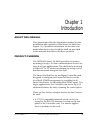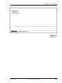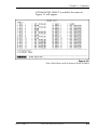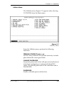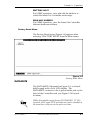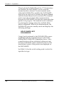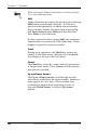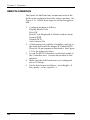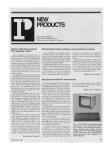
1
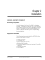
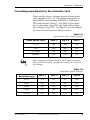
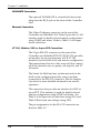
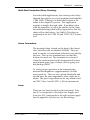
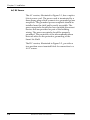
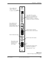
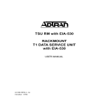
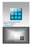
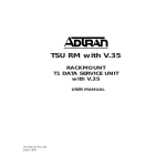
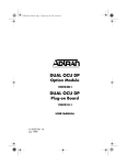
Smart 16e Shelf
with embedded SNMP
USER MANUAL
4200023L5
4200023L6
61200.162L1-1A
January 1997
AC Version
DC Version
901 Explorer Boulevard
P.O. Box 140000
Huntsville, AL 35814-4000
Phone: (205) 963-8000
© 1997 ADTRAN, Inc.
All rights reserved.
Printed in USA.
FCC regulations require that the following information be provided in this manual:
1. This equipment complies with Part 68 of the FCC rules. On the bottom of the
equipment housing is a label that shows the FCC registration number and Ringer
Equivalence Number (REN) for this equipment. If requested, provide this
information to the telephone company (REN is not required for some types of
analog or digital facilities).
2. If this equipment causes harm to the telephone network, the telephone company may
temporarily discontinue service. If possible, advance notification is given;
otherwise, notification is given as soon as possible. The telephone company will
advise the customer of the right to file a complaint with the FCC.
3. The telephone company may make changes in its facilities, equipment, operations,
or procedures that could affect the proper operation of this equipment; advance
notification and the opportunity to maintain uninterrupted service are given.
4. If experiencing difficulty with this equipment, please contact ADTRAN for repair
and warranty information. The telephone company may require this equipment to
be disconnected from the network until the problem is corrected or it is certain the
equipment is not malfunctioning.
5. This unit contains no user serviceable parts.
6. An FCC compliant telephone cord with a modular plug is provided with this
equipment. In addition, an FCC compliant cable appropriate for the dial backup
option ordered is provided with this equipment. This equipment is designed to be
connected to the telephone network or premises wiring using an FCC compatible
modular jack, which is Part 68 compliant.
7. The following information may be required when applying to the local telephone
company for leased line facilities:
Service
Type
2.4 kbps Digital Interface
4.8 kbps Digital Interface
9.6 kbps Digital Interface
19.2 kbps Digital Interface
38.4 kbps Digital Interface
56 kbps Digital Interface
64 kbps Digital Interface
Digital Facility
Interface Code
Service Order
Code
Network
Jacks
04DU5-24
04DU5-48
04DU5-96
04DU5-19
04DU5-38
04DU5-56
04DU5-64
6.0F
6.0F
6.0F
6.0F
6.0F
6.0F
6.0F
RJ-48S
RJ-48S
RJ-48S
RJ-48S
RJ-48S
RJ-48S
RJ-48S
8. In the event of equipment malfunction, all repairs should be performed by
ADTRAN. It is the responsibility of users requiring service to report the need for
service to their distributor or ADTRAN. See the last page of this manual for
information on contacting ADTRAN for service.
Federal Canadian Emissions Requirements
Radio Frequency Interference Statement
This equipment has been tested and found to comply with the limits for a Class A digital device,
pursuant to Part 15 of the FCC Rules. These limits are designed to provide reasonable protection
against harmful interference when the equipment is operated in a commercial environment. This
equipment generates, uses, and can radiate radio frequency energy and, if not installed and used
in accordance with the instruction manual, may cause harmful interference to radio frequencies.
Operation of this equipment in a residential area is likely to cause harmful interference in which
case the user will be required to correct the interference at his own expense.
Shielded cables must be used with this unit to ensure compliance with Class A FCC limits.
Change or modifications to this unit not expressly approved
by the party responsible for compliance could void the user's
authority to operate the equipment.
CANADIAN EMISSIONS REQUIREMENTS
This digital apparatus does not exceed the Class A limits for radio noise
emissions from digital apparatus as set out in the interference-causing
equipment standard entitled "Digital Apparatus," ICES-003 of the Department of Communications.
Cet appareil nuerique respecte les limites de bruits radioelectriques
applicables aux appareils numeriques de Class A prescrites dans la norme
sur le materiel brouilleur: "Appareils Numeriques," NMB-003 edictee par le
ministre des Communications.
CANADIAN EQUIPMENT LIMITATIONS
Notice: The Canadian Industry and Science Canada label identifies certified
equipment. This certification means that the equipment meets certain telecommunications network protective, operational, and safety requirements.
The Department does not guarantee the equipment will operate to the user's
satisfaction.
Before installing this equipment, users should ensure that it is permissible to
be connected to the facilities of the local telecommunications company. The
equipment must also be installed using an acceptable method of connection.
In some cases, the company's inside wiring associated with a single line
individual service may be extended by means of a certified connector assembly (telephone extension cord). The customer should be aware that compliance with the above conditions may not prevent degradation of service in
some situations.
Repairs to certified equipment should be made by an authorized Canadian
maintenance facility designated by the supplier. Any repairs or alterations
made by the user to this equipment, or equipment malfunctions, may give the
telecommunications company cause to request the user to disconnect the
equipment.
Users should ensure for their own protection that the electrical ground
connections of the power utility, telephone lines and internal metallic water
pipe system, if present, are connected together. This precaution may be
particularly important in rural areas.
Users should not attempt to make such connections themselves, but should contact the appropriate electric inspection
authority, or an electrician, as appropriate.
The Load Number (LN) assigned to each terminal device denotes the percentage of the total load to be connected to a telephone loop which is used by the
device, to prevent overloading. The termination on a loop may consist of any
combination of devices subject only to the requirement that the total of the
Load Numbers of all devices does not exceed 100.
Table of Contents
Table of Contents
Table of Contents
Chapter 1. Introduction
About This Manual ............................................................................................ 1
Product Overview ............................................................................................. 1
Warranty and Customer Service ...................................................................... 3
Chapter 2. Installation
Unpack, Inspect, Power Up .............................................................................. 5
Receiving Inspection .................................................................................. 5
Equipment Included .................................................................................. 5
Customer Provides ..................................................................................... 6
Power Up ..................................................................................................... 6
Installation into Cabinet or Rack ..................................................................... 7
Installation of Power Supplies ......................................................................... 7
Installation of Controller Card ......................................................................... 8
Connecting Input Devices to the Controller Card ................................. 9
DATAMATE Connection ................................................................. 10
Ethernet Connection ......................................................................... 10
VT 100, Modem, SLIP, or Async PPP Connection ........................ 10
Multi-Shelf Connection (Daisy Chaining) ..................................... 11
Alarm Connections ........................................................................... 11
Fuses .................................................................................................... 11
AC/DC Power ................................................................................... 12
Chapter 3. Operation
Local Operation................................................................................................ 17
VT 100 Terminal ....................................................................................... 17
Operation ............................................................................................ 17
Connection ......................................................................................... 17
Jumper and Switch Settings ............................................................. 19
Main Menu ......................................................................................... 20
Select Unit Menu ............................................................................... 22
Alarm Menu ....................................................................................... 24
Utilities Menu .................................................................................... 25
Factory Reset Menu .......................................................................... 27
DATAMATE ............................................................................................. 27
Manual Operation and Button Functions ...................................... 29
Remote Operation ............................................................................................ 32
61200.162L1-1
Smart 16e Shelf User Manual
i
Table of Contents
Operation with a Network Manager
Using the SLIP, Async PPP, or Ethernet Interface ....................................... 34
Configure Network Interface Using a VT 100 Terminal ............................ 34
Using Telnet ...................................................................................................... 35
Multi-Shelf Operation (Daisy Chaining) ...................................................... 36
Interpreting Alarms and Error Messages ............................................. 39
Clearing DBU Alarms .............................................................................. 41
Appendix A. Specifications ......................................................................... 43
Index .................................................................................................................. 47
List of Tables
Table 2-A Input Device Type Switch Settings ............................................ 9
Table 2-B Baud Rate Switch Settings .......................................................... 9
Table 2-C Pin Assignments for EIA-232 Connector ................................ 13
Table 2-D Pin Assignments for CTRL IN and CTRL OUT Connectors 13
Table 3-A Switch 1 Shelf Numbering Settings ......................................... 38
Table 3-B Controller Card Error Messages .............................................. 39
Table 3-C LED Alarm Messages ................................................................ 41
List of Figures
Figure 1-1 Smart 16e Shelf ............................................................................. 2
Figure 2-1 Rear AC Power/Control Segment ........................................... 14
Figure 2-2 Rear DC Power/Control Segment ........................................... 15
Figure 3-1 Local Configuration ................................................................... 18
Figure 3-2 Jumper and Switch Locations .................................................. 19
Figure 3-3 Main Menu .................................................................................. 21
Figure 3-4 Select Unit Menu with Enhanced Select Disabled ................ 22
Figure 3-5 Select Unit Menu with Enhanced Select Enabled .................. 23
Figure 3-6 Alarm Menu ................................................................................ 24
Figure 3-7 Utilities Menu ............................................................................. 25
Figure 3-8 Factory Reset Menu ................................................................... 27
Figure 3-9 DATAMATE ................................................................................ 29
Figure 3-10 DATAMATE Utility Menu ........................................................ 31
Figure 3-11 Remote Configuration ............................................................... 33
Figure 3-12 Controller Configuration Switch Positions ............................ 36
Figure 3-13 Multi-Shelf Application ............................................................. 37
Figure 3-14 Controller Card Front Panel ..................................................... 40
ii
Smart 16e Shelf User Manual
61200.162L1-1
Chapter 1. Introduction
Chapter 1
Introduction
ABOUT THIS MANUAL
This manual provides the information needed for the
installation and operation of the Smart 16e Shelf (see
Figure 1-1). Operation instructions for the data communication devices used with the shelf are provided
in the manuals furnished with those products.
PRODUCT OVERVIEW
The ADTRAN Smart 16e Shelf provides convenient
mounting for up to 16 data communication devices for
large host-type applications. The shelf can be mounted
in either 19" or 23" racks and cabinets by using a set of
brackets mounted alongside the shelf.
The Smart 16e Shelf has an intelligent Controller card
designed to configure and control all devices in the
local shelf. SNMP management is available for all
Smart 16e devices via the embedded SNMP agent. For
larger applications, the Controller can access up to 15
additional shelves by daisy-chaining the control ports.
There are five choices of input devices for the Controller card:
• A VT 100 compatible terminal which can be connected to the EIA-232 interface, located on the rear
panel of the Controller card. For remote applications, a modem can be used.
61200.162L1-1
Smart 16e Shelf User Manual
1
Chapter 1. Introduction
• The optional DATAMATE, a hand-held keypad with
a 2 x 16 LCD display. This unit plugs into the RJ-11
jack on the front of the Controller card.
• A device running SLIP protocol. A SLIP interface
(the EIA-232 interface) is located on the rear panel of
the Controller card. For remote applications, a
modem can be used.
• A device running async PPP protocol. An async PPP
interface (the EIA-232 interface) is located on the
rear panel of the Controller card. For remote
applications, a modem can be used.
• A LAN running ethernet protocol. An ethernet
10baseT interface is located on the rear panel of the
Controller card.
The shelf and all installed units are internally powered
by an AC or DC supply. An optional second power
supply can be used for backup protection.
DSU III AR
DSU III AR
DSU III AR
RS
RS
RS
RS
RS
RS
RS
RS
CS
CS
CS
DSU III AR
CS
DSU III S4W
CS
DSU III S4W
CS
DSU III S4W
CS
DSU III S4W
CS
TD
TD
TD
TD
TD
TD
TD
TD
RD
RD
RD
RD
RD
RD
RD
RD
CD
CD
CD
CD
CD
CD
CD
CD
ALM
ALM
ALM
ALM
ALM
ALM
ALM
ALM
DSU III DBU
DSU III TDM
P
O
R
T
EC
CH
-5V
-12V
+12V
+5V
EC
CH
-5V
-12V
+12V
+5V
SHELF
CONTROLLER
K
POWER SUPPLY
K
POWER SUPPLY
DSU III DBU
DSU S2W
DSU S2W
DSU S2W
1
RS
RS
RS
RS
RS
RS
2
CS
CS
CS
CS
CS
CS
3
TD
TD
TD
TD
TD
TD
4
RD
RD
RD
RD
RD
RD
SELECT
CD
CD
CD
CD
CD
CD
ALM
ALM
ALM
ALM
ALM
ALM
DTE
DTE
DTE
DTE
DTE
LOOP
LOOP
LOOP
LOOP
LOOP
RDL
RDL
RDL
RDL
RDL
PTRN
PTRN
PTRN
PTRN
PTRN
ERROR
ERROR
ERROR
ERROR
ERROR
SELECT
SELECT
SELECT
SELECT
SELECT
TEST
TEST
TEST
TEST
TEST
DBU
DTE
DTE
DTE
DTE
DTE
DTE
DTE
DTE
LOOP
LOOP
LOOP
LOOP
LOOP
LOOP
LOOP
LOOP
RDL
RDL
RDL
RDL
RDL
RDL
RDL
RDL
PTRN
PTRN
PTRN
PTRN
PTRN
PTRN
PTRN
PTRN
DTE
LOOP
RDL
ERROR
ERROR
ERROR
ERROR
ERROR
ERROR
ERROR
ERROR
DATAMATE
T
E
S
T
ENTER
CANCEL
A
1
D
4
B
2
E
5
C
3
F
6
7
SHIFT
*
8
9
QUICK
#
0
1
PTRN
ERROR
SELECT
SELECT
SELECT
SELECT
SELECT
SELECT
SELECT
SELECT
SELECT
TEST
TEST
TEST
TEST
TEST
TEST
TEST
TEST
7
8
9
2
3
4
5
6
TEST
10
11
12
13
14
15
16
Figure 1-1
Smart 16e Shelf
2
Smart 16e Shelf User Manual
61200.162L1-1
Chapter 1. Introduction
WARRANTY AND CUSTOMER SERVICE
ADTRAN will replace or repair this product within
five years from the date of shipment if it does not meet
its published specifications or fails while in service.
For detailed warranty, repair, and return information
refer to the ADTRAN Equipment Warranty and Repair
and Return Policy Procedure.
Return Material Authorization (RMA) is required
prior to returning equipment to ADTRAN.
For service, RMA requests, or further information,
contact one of the numbers listed on the last page of
this manual.
61200.162L1-1
Smart 16e Shelf User Manual
3
Chapter 1. Introduction
4
Smart 16e Shelf User Manual
61200.162L1-1
Chapter 2. Installation
Chapter 2
Installation
UNPACK, INSPECT, POWER UP
Receiving Inspection
Carefully inspect the Smart 16e Shelf for shipping
damage. If damage is suspected, file a claim immediately with the carrier and contact ADTRAN Customer
Service. If possible, keep the original shipping container to ship the shelf for repair or verify damage
during shipment.
Equipment Included
The following items are included in ADTRAN shipments of the Smart 16e Shelf:
• Smart 16e chassis
• Controller card
• Power supply (AC or DC)
• Blank power faceplate
• Rear panel segment for power input and Controller
operation
• Mounting brackets
• User manual
61200.162L1-1
Smart 16e Shelf User Manual
5
Chapter 2. Installation
Customer Provides
The customer must supply the following items:
• A PC capable of emulating VT 100 for configuring
devices installed in the Smart 16e Shelf.
• An EIA-232 cable for connection to the VT 100
interface.
• Optionally, a DATAMATE (part number 1200045L1)
which can be used for most shelf configuration.
• For SNMP access, a cable for connection to either the
Controller card's EIA-232 connector (for SLIP or PPP
async protocol) or the card's 10baseT interface (for
ethernet protocol).
The VT 100 interface is required for setting up the initial
network settings for SLIP, async PPP, or ethernet communications.
Power Up
The shelf and installed units are internally powered by
an AC or DC supply. An optional second power
supply can be used for redundant protection.
6
Smart 16e Shelf User Manual
61200.162L1-1
Chapter 2. Installation
INSTALLATION INTO CABINET OR RACK
The set of brackets supplied with the Smart 16e Shelf
can be used for either 19" or 23" applications. For 19"
applications, the longer side of the bracket should be
flush with the side of the chassis. For 23" applications,
the short side of the bracket should be flush with the
side of the chassis.
There are two sets of mounting holes for the brackets
on the left and right sides of the Smart 16e Shelf. One
set positions the front of the Smart 16e Shelf in line
with the front of the rack. The other set extends the
front of the Smart 16e Shelf beyond the front of the
rack.
INSTALLATION OF POWER SUPPLIES
The power supply can be installed in either of the two
slots at the top of the Smart 16e Shelf. If only one
power supply is used, the blank power supply faceplate furnished with the rack should be installed over
the unused slot.
The Smart 16e Shelf is fully operational with one
power supply; however, a second supply can be
added to provide backup for the power supply
subsystem. With the two-supply configuration, one of
the supplies will operate in a hot-standby mode (the
corresponding output on the standby supply will
automatically provide the power required if any one
of the four outputs from a supply fails or begins to
operate out of specifications).
The power supplies can be "hot swapped".
Slide the power supply along the card guides of one of
the top slots until it is fully seated in the connector and
the faceplate is flush with the chassis. Tighten the
screws on the front of the power supply panel.
61200.162L1-1
Smart 16e Shelf User Manual
7
Chapter 2. Installation
Each power supply has a green indicator for each of
the output voltages (+5V, -5V, +12V, and -12V) as well
as a red indicator to indicate an alarm condition.
Illumination of a green LED indicates that the corresponding voltage is operating properly. When operation of any one of the four voltages drops out of
specifications, the green LED for that voltage will go
out and the red LED will come on.
Only personnel familiar with installation and maintenance
of the Smart 16 Shelf should install or replace the power
supplies. A shock hazard could be present if an empty
power supply slot is left uncovered.
INSTALLATION OF CONTROLLER CARD
The Smart 16e Shelf has 17 vertical slots in the front
and rear of the chassis. The left-most front position is
reserved for the Smart 16e Shelf Controller card. All
other front slots can be used in any order for
rackmount cards. The PWR/CTRL rear segment
occupies the slot behind the Smart 16e Controller card.
All other rear slots are for DTE/Network Interface
Cards.
The rear segment is already installed. The Controller
card slides into the corresponding front slot until
contact is made with both the backplane connector
and the rear segment connector and the panel is flush
with the front of the chassis. The Controller card may
be inserted and removed while the Smart 16e Shelf is
receiving power.
The card can appear to be operational (i.e., receiving power)
and yet may not be completely connected. The rear segment
must be fully seated and the screws must be tight for proper
operation.
8
Smart 16e Shelf User Manual
61200.162L1-1
Chapter 2. Installation
Connecting Input Devices to the Controller Card
There are five choices of input devices for the Smart
16e Controller card: a VT 100 terminal, the optional
DATAMATE (part number 1200045L1), SLIP, async
PPP, and ethernet 10baseT . See Table 2-A for input
device selections using SW1 and Table 2-B for baud
rate settings using SW2. See Figure 3-1 in the chapter
Operation for the location of these switches.
Table 2-A
Input Device Type Switch Settings
Input Device Type
SW1-5
SW1-6
SW1-7
VT 100
ON
ON
ON
SLIP
OFF
ON
ON
PPP Async
ON
ON
OFF
Ethernet
ON
OFF
ON
After changing a switch setting or the IP address information, pull the Controller card out and reinsert it to activate
the changes.
Table 2-B
Baud Rate Switch Settings
Baud Rate (bps)
SW2-1
SW2-2
SW2-3
SW2-4
9600
ON
ON
ON
ON
19200
OFF
ON
ON
ON
38400
ON
OFF
ON
ON
57600
OFF
OFF
ON
ON
115200
ON
ON
OFF
ON
61200.162L1-1
Smart 16e Shelf User Manual
9
Chapter 2. Installation
DATAMATE Connection
The optional DATAMATE is a hand-held device that
plugs into the RJ-11 jack on the front of the Controller
card.
Ethernet Connection
The 10baseT ethernet connector on the rear of the
Controller card labelled LAN 10baseT provides a LAN
interface used for both local and remote configuration
using SNMP and telnet. Refer to Table 2-A for input
device selections.
VT 100, Modem, SLIP, or Async PPP Connection
The 25-pin EIA-232 connector on the rear of the
Controller card (labelled DTE/DCE EIA 232) provides
an interface for an asynchronous ASCII VT 100
terminal, used for both local and remote configuration.
The terminal must be set to line wrap off, flow control
off, 8-bit character size, no parity, one stop bit, and VT
100 mode.
The Smart 16e Shelf and any rackmount units in the
shelf can be configured remotely using a modem
connected to the EIA-232 connector. See the chapter
Operation for more detailed information on remote
operation.
This connector also provides an interface for SLIP or
async PPP. This interface is used for both local and
remote configuration using SNMP and telnet. See
Table 2-A for input device selections using SW1 and
Table 2-B for baud rate settings using SW2.
The pin assignments for the EIA-232 connector are
listed in Table 2-C.
10
Smart 16e Shelf User Manual
61200.162L1-1
Chapter 2. Installation
Multi-Shelf Connection (Daisy Chaining)
For multi-shelf applications, the control port is daisychained through the two 6-pin modular jacks labelled
CTRL LINK. Cabling of a multi-shelf system is detailed in the chapter Operation. This application
requires a straight through cable. If problems arise
with the operation of one of the shelves in the chain,
the malfunctioning shelf will be bypassed so that the
chain will not be broken. See Table 2-D for the pin
assignments for the CTRL IN and CTRL OUT connectors.
Alarm Connections
The terminal strips located on the back of the Smart
16e Controller card are labeled ALARM. They are
used for audio or visual alarm indicators provided by
the user. The top two terminals are a set and the
bottom two are a set. The terminals are activated
when the cards inserted in the designated slots have
encountered some type of alarm, such as going into
dial backup (DBU).
To verify proper operation of the terminal strip,
measure the impedance (approximately 0.6 ohm)
across each set. The two sets operate identically and
should have the same impedance when cards are in
alarm. The power specifications for any alarms used
are NEC Class 2 and 48 VDC @ 500 mA maximum.
Fuses
There are two fuses located on the rear panel. Fuse
one (F1) corresponds to the left power supply, and
Fuse two (F2) corresponds to the right power supply.
See the appendix Specifications for fuse ratings.
61200.162L1-1
Smart 16e Shelf User Manual
11
Chapter 2. Installation
AC/DC Power
The AC version, illustrated in Figure 2-1, has a captive
8-foot power cord. The power cord is terminated by a
three-prong plug which connects to a grounded power
receptacle. The grounded power receptacle should be
installed near the shelf and be easily accessible. The
power receptacle should also have suitable disconnect
devices that are provided as part of the building
wiring. The power receptacle should be properly
grounded. The protection of the telecommunications
network relies on the protective grounding of the
Smart 16e Shelf.
The DC version, illustrated in Figure 2-2, provides a
two-position screw terminal block for connection to a
-48 V source.
12
Smart 16e Shelf User Manual
61200.162L1-1
Chapter 2. Installation
Table 2-C
Pin Assignments for EIA-232 Connector
Pin
1
2
3
4
5
6
7
8
9
10
15
17
18
20
21
22
24
25
EIA
AA
BA
BB
CA
CB
CC
AB
CF
DB
DD
CD
CE
DA
-
Description
Protective Ground (PG)
Transmit Data (TD)
Receive Data (RD)
Request to Send (RS)
Clear to Send (CS)
Data Set Ready (SR)
Signal Ground (SG)
Received Line Signal Detector (CD)
+12 Test Point
-12 Test Point
Transmit Clock (TC)
Receive Clock (RC)
Local Loopback (LL)
Data Terminal Ready (TR)
Remote Loopback (RL)
Ring Indicator (RI)
External TX Clock (ETC)
Test Indicator (TI)
Table 2-D
Pin Assignments for CTRL IN and CTRL OUT Connectors
1
2
3
4
5
6
61200.162L1-1
CTRL IN
GND
RX CTL IN RX CTL IN +
TX CTL IN TX CTL IN +
GND
Smart 16e Shelf User Manual
1
2
3
4
5
6
CTRL OUT
GND
TX CTL OUT TX CTL OUT +
RX CTL OUT RX CTL OUT +
GND
13
Chapter 2. Installation
SMART 16e
SHELF
CONTROLLER
8-pin modular jack
used for Ethernet
10 base T connection
L
A
N
10 BASE T
25-pin EIA-232 connector
interface for connection to an
asynchronous ASCII VT 100
terminal, a modem, or a device
running SLIP or async PPP protocol
D
T
E
/
D
C
E
E
I
A
2
3
2
6-pin modular jacks
for daisy-chaining
shelves together (use
straight through cable)
I
N
C
T
R
L
L
I
N
K
O
U
T
N
E
C
C
L
A
S
S
A
L
A
R
M
Terminal strip for external
alarm circuits or other devices
2
I
N
P
U
T
Fuse for left power supply
3A
3AG
F1
Fuse for right power supply
3A
3AG
F2
Captive 8-foot power cord
115V AC
60 HZ
2 AMPS
Figure 2-1
Rear AC Power/Control Segment
14
Smart 16e Shelf User Manual
61200.162L1-1
Chapter 2. Installation
SMART 16e
SHELF
CONTROLLER
8-pin modular jack
used for Ethernet
10 base T connection
L
A
N
10 BASE T
D
T
E
/
D
C
E
25-pin EIA-232 connector
interface for connection to an
asynchronous ASCII VT 100
terminal, a modem, or a device
running SLIP or async PPP protocol
E
I
A
2
3
2
6-pin modular jacks
for daisy-chaining
shelves together (use
straight through cable)
I
N
C
T
R
L
L
I
N
K
O
U
T
N
E
C
A
L
A
R
M
C
L
A
S
S
Terminal strip for external
alarm circuits or other devices
2
I
N
P
U
T
Fuse for left power supply
F1
5A
3AG
F2
5A
3AG
Fuse for right power supply
Two-position screw
terminal block for
connection to a
-48 V source
(+)
(-)
-48V
-48V
RET
-48VDC
NEC CLASS 2
INPUT
External Power Supply Specs:
Input=120 VAC @60 Hz
Output=48 VDC, 6 mA
Figure 2-2
Rear DC Power/Control Segment
61200.162L1-1
Smart 16e Shelf User Manual
15
Chapter 2. Installation
16
Smart 16e Shelf User Manual
61200.162L1-1
Chapter 3. Operation
Chapter 3
Operation
LOCAL OPERATION
There are five methods of local configuration for the
Smart 16e Shelf: a VT 100 terminal, DATAMATE (part
number 1200045L1), SLIP, async PPP, and ethernet
10baseT.
If enabled, the password parameter protects the
terminal interface from unauthorized configuration.
VT 100 Terminal
Operation
The Smart 16e Shelf may be configured by attaching a
VT 100 compatible terminal or equivalent to the
control port on the rear of the Smart 16e Shelf Controller card. The terminal must be set to line wrap off,
flow control off, and VT 100 mode. The Controller
card settings are as follows: 9600 to 115.2k bps baud
rate, 8-bit character size, no parity, and one stop bit.
Connection
The connection to a terminal is made through the EIA232 25-pin connector on the rear PWR/CTRL segment
(see Figure 3-1). This connection is used for both local
and remote configuration.
61200.162L1-1
Smart 16e Shelf User Manual
17
Chapter 3. Operation
SMART 16e
SHELF
CONTROLLER
L
A
N
10 BASE T
D
T
E
/
D
C
E
E
I
A
2
3
2
I
N
C
T
R
L
L
I
N
K
O
U
T
N
E
C
C
L
A
S
S
A
L
A
R
M
2
I
N
P
U
T
3A
3AG
F1
3A
3AG
F2
115V AC
60 HZ
2 AMPS
Figure 3-1
Local Configuration
18
Smart 16e Shelf User Manual
61200.162L1-1
Chapter 3. Operation
Jumper and Switch Settings
For local configuration, place the jumper on the
header of JP5 labeled DCE. If only one shelf is being
used, the shelf must be configured as the master (SW18 on). See Figure 3-2 for jumper and switch locations.
See the section Multi-Shelf Operation in this chapter for
information on switch settings in a multiple shelf
configuration.
If only one shelf is being used, the shelf must be configured
as the master (SW1-8 on).
After changing a switch setting or the IP address information, pull the Controller card out and reinsert it to activate
the changes.
Fuses
F1
F3
F2
JP5
DCE
JP1
O 1 2 3 4 5 6 7 8
N
SW2
SW1
DTE
O 1 2 3 4
N
Switch 1 sets shelf number,
master/slave operation, and
input device selection. See
Table 2-A and Figure 3-12.
Switch 2 sets the baud rate.
See Table 2-B.
Jumpers configure the
card for local (direct)
or remote (modem)
operation.
Figure 3-2
Jumper and Switch Locations
61200.162L1-1
Smart 16e Shelf User Manual
19
Chapter 3. Operation
Main Menu
After initiating terminal mode by pressing the Return
key until the Main menu appears, the display will
divide into three sections (see Figure 3-3):
1.
2.
3.
The main window which displays all options of a
menu level.
The information window which lists all possible
choices for a selected option.
The command line which displays the current
setting for a selected option. The setting can be
updated by entering the number corresponding to
the desired selection, followed by a carriage
return. The new setting will be updated in the
main window.
From the Main menu, select a unit, view alarms of
individual units, access a utility menu, or reset the
shelf to the following factory default settings:
TIME= 00:00:00
DATE= 00-00-00
TIMEOUT LIMIT=0
SNMP PHONE NUMBERS=(blank)
PASSWORD=PASSWORD
IP ADDRESS=0.0.0.0
SUBNET MASK=255.255.255.0
GW IP ADDRESS=0.0.0.0
TRAP HOST IP=0.0.0.0
The following settings are only available with the VT
100 interface:
SNMP GET COMMUNITY=public
SNMP SET COMMUNITY=private
SNMP TRAP COMMUNITY=SNMP_trap
20
Smart 16e Shelf User Manual
61200.162L1-1
Chapter 3. Operation
Figure 3-3
Main Menu
61200.162L1-1
Smart 16e Shelf User Manual
21
Chapter 3. Operation
Select Unit Menu
The Select Unit menu, illustrated in Figure 3-4, appears after selecting 1 SELECT UNIT from the Main
menu with ENHANCED SELECT in the Utilities
menu disabled.
Press 1 to select the shelf number (displayed on the
front of the shelf Controller card).
Press 2 to select the slot number.
Press 3 to execute the choices and begin configuring
the rackmount unit.
Figure 3-4
Select Unit Menu with Enhanced Select Disabled
22
Smart 16e Shelf User Manual
61200.162L1-1
Chapter 3. Operation
If ENHANCED SELECT is enabled, the menu in
Figure 3-5 will appear.
Figure 3-5
Select Unit Menu with Enhanced Select Enabled
61200.162L1-1
Smart 16e Shelf User Manual
23
Chapter 3. Operation
Alarm View Menu
The Alarm menu (Figure 3-6) appears after selecting 2
ALARM VIEW from the Main menu. This menu
displays the current system status. Select any active
shelf and slot number to view its status.
Figure 3-6
Alarm Menu
24
Smart 16e Shelf User Manual
61200.162L1-1
Chapter 3. Operation
Utilities Menu
The Utilities menu (Figure 3-7) appears after selecting
3 UTILITIES from the Main menu.
Figure 3-7
Utilities Menu
From the Utilities menu, perform the following
functions:
TERMINAL TIMEOUT (min) = nn
Set how many minutes of keyboard inactivity can take
place before the screen goes blank.
CHANGE PASSWORD
Set private password which will prevent unauthorized
users from configuring or testing individual DSU
cards. The default password for the controller card is
PASSWORD.
PASSWORD
Enable or disable password function.
61200.162L1-1
Smart 16e Shelf User Manual
25
Chapter 3. Operation
SET TIME
Set time of day.
SET DATE
Set the date.
EDIT SHELF/SLOT DESCRIPTIONS
Assign names to the shelves and slots.
TERMINAL ALARM
Enable or disable terminal alarm function.
ENHANCED SELECT
If enabled, the Select Unit menu shown in Figure 3-4
will be replaced with the menu in Figure 3-5.
EDIT SNMP PHONE NUMBER
For SNMP dial up operation, enter the phone number
that the Controller calls to send an SNMP trap.
EDIT SNMP GET COMMUNITY
For SNMP operation, view and edit the SNMP GET
community string.
EDIT SNMP SET COMMUNITY
For SNMP operation, view and edit the SNMP SET
community string.
EDIT SNMP TRAP COMMUNITY
For SNMP operation, view and edit the SNMP trap
community string.
EDIT IP ADDRESS
For SNMP and telnet operation, view and edit the
Smart 16e Controller IP address.
EDIT SUBNET MASK
For SNMP and telnet operation, view and edit the
Smart 16e Controller subnet mask.
EDIT GATEWAY ADDRESS
For SNMP and telnet operation, view and edit the
Smart 16e Controller gateway address.
26
Smart 16e Shelf User Manual
61200.162L1-1
Chapter 3. Operation
EDIT TRAP HOST
For SNMP operation, view and edit the address to
which the Smart 16e Controller sends traps.
READ MAC ADDRESS
For SNMP operation, view the Smart 16e Controller
ethernet hardware address.
Factory Reset Menu
The Factory Reset menu (Figure 3-8) appears after
selecting 4 FACTORY RESET from the Main menu.
Figure 3-8
Factory Reset Menu
DATAMATE
The DATAMATE, illustrated in Figure 3-9, is a handheld keypad with a 2x16 LCD display. The
DATAMATE connects to the 6-pin modular jack on the
front of the Controller card (see Figure 3-14 for jack
location).
While all controller input devices (DATAMATE, VT 100
terminal, SLIP, async PPP, and ethernet) can be installed at
the same time, only one can be active at a time.
61200.162L1-1
Smart 16e Shelf User Manual
27
Chapter 3. Operation
When both the DATAMATE and the VT 100 interfaces
are installed, the DATAMATE is active until the
terminal mode is selected. To enter terminal mode
while the DATAMATE is installed, the DATAMATE
must be in the top level of its menu tree (press Cancel
until the desired menu level is reached). The terminal
mode cannot be activated while communication
between the DATAMATE and the data communication
product is in progress. The terminal mode is initiated
by pressing the carriage return key until the Main
menu is displayed. While in the terminal mode, the
DATAMATE goes into standby mode and displays the
following message:
HOLD CANCEL KEY
FOR SERVICE
Control can be returned to the DATAMATE by pressing Escape until the terminal mode is exited or by
holding the DATAMATE's Cancel key down. Once
communication with an individual rackmount unit
has been established, menus identical to those of the
stand alone version of the product are displayed on
the DATAMATE.
See Table 2-A for the switch setting used to select the
input device type .
28
Smart 16e Shelf User Manual
61200.162L1-1
Chapter 3. Operation
Displays menu
items and messages
Use arrows to scroll
through submenu
items
Press before
desired alpha
character selection
DATAMATE
ENTER
CANCEL
A
1
D
4
B
2
E
5
C
3
F
6
7
SHIFT
8
*
0
9
QUICK
#
Press to select active
(flashing) menu items
Press to stop current
activity and return
to previous menu
Use numeric keypad
to activate menu items
and enter parameters
Press to return to the Main menu
Figure 3-9
DATAMATE
Manual Operation and Button Functions
The following function descriptions apply to the
DATAMATE. The DATAMATE's Utility menu is
provided in Figure 3-10.
LCD Window
Displays menu items and messages in 2 lines by 16
characters.
Enter
Selects active menu items. To activate a menu item,
press the number of the item. When the menu item is
flashing, press Enter to select it. This action displays
a submenu item (if there is one) or sets the configuration parameter. The display of COMMAND ACCEPTED indicates a valid operation.
Numeric Keypad
The numeric keypad contains the numbers 0 through 9
and alpha characters A through F, which are used to
activate menu items. Numbers 0 through 9 are also
used to enter parameters.
61200.162L1-1
Smart 16e Shelf User Manual
29
Chapter 3. Operation
When entering IP address information, use the pound key
(#) to insert decimal points.
Shift
Alpha characters are entered by pressing and releasing
Shift before each desired character. To activate a
menu item designated by an alpha character rather
than a number, display the menu item using the Up
and Down Arrows, press Shift and then the letter.
Press Enter to select the item.
If a key is pressed without using Shift, the numbered
item becomes active instead of the alpha item. If this
happens, repeat the correct procedure.
Quick
During most operations, the Quick key returns the
display to the Main menu. During a test, the Quick
key returns to the top of the Test menu.
Cancel
The Cancel key stops the current activity and returns
to the previous menu. Press Cancel until the desired
menu level is reached.
Up and Down Arrows
The Up and Down Arrows scroll through the submenu items available in the current menu. Submenu
items appear two at a time. When scrolled, they
continuously appear from beginning to end in a
forward (Down Arrow) or reverse (Up Arrow)
pattern.
30
Smart 16e Shelf User Manual
61200.162L1-1
Chapter 3. Operation
1=SELECT UNIT
SHELF=x
SLOT=x
Yields individual
unit's menu
2=UTILITIES
1=SET TIME
SHELF=x
TIME 04:23:44
xx:xx:xx
2=SET DATE
SHELF=x
DATE 08-15-97
xx-xx-xx
3=TIMEOUT LIMIT
TIME OUT TIMER
TIMER=0 MIN.
4=SOFTWARE REV.
SOFTWARE REV=x
CHECKSUM=xxxx
5=SNMP PHONE NUMBER xxxxxxxx
6=SET PASSWORD
xxxxxxxx
7=IP ADDRESS
xxxxxxxx
8=SUBNET MASK
xxxxxxxx
9=GW IP ADDRESS
xxxxxxxx
A=TRAP HOST
xxxxxxxx
B=MAC ADDRESS
xxxxxxxx
3=FACTORY RESET ARE YOU SURE?
SHELF=x
4=ALARM CLEAR
ARE YOU SURE?
SHELF=x
Figure 3-10
DATAMATE Utility Menu
61200.162L1-1
Smart 16e Shelf User Manual
31
Chapter 3. Operation
REMOTE OPERATION
The Smart 16e Shelf and any rackmount units in the
shelf can be configured remotely using a modem. See
Figure 3-11. Follow these steps to set up this application:
1.
2.
3.
4.
5.
32
Configure modem as follows:
Display Result Code
Echo Off
Result Code Displayed as Words (verbose form)
Normal DTR
Normal DCD
Auto Answer On
At the remote site, pull the Controller card out of
the shelf and locate the Jumper JP1 labeled DTE.
Place the 18-pin jumper on the header. See Figure
3-1 for the jumper location.
Locate the EIA-232 interface on the back panel of
the Controller card. Connect the modem to this
interface.
Make sure the shelf baud rate is not configured
above 19.2 kbps.
Set the data format as follows: word length = 8
bits, parity = none, stop bit = 1.
Smart 16e Shelf User Manual
61200.162L1-1
Chapter 3. Operation
SMART 16e
SHELF
CONTROLLER
L
A
N
10 BASE T
D
T
E
/
D
C
E
MODEM
E
I
A
PSTN
2
3
2
I
N
C
T
R
L
L
I
N
K
O
U
T
MODEM
N
E
C
C
L
A
S
S
A
L
A
R
M
2
I
N
P
U
T
3A
3AG
F1
3A
3AG
F2
115V AC
60 HZ
2 AMPS
Figure 3-11
Remote Configuration
61200.162L1-1
Smart 16e Shelf User Manual
33
Chapter 3. Operation
OPERATION WITH A NETWORK MANAGER
USING THE SLIP, ASYNC PPP, OR ETHERNET INTERFACE
Before SLIP, async PPP, or ethernet communication can
be established with a network manager, some initial
network settings must be configured using a local VT
100 terminal attached to the EIA-232 port of the Smart
16e Controller card.
Obtain information such as the internet protocol (IP)
address, subnet mask, gateway IP address, and trap host IP
address from the network administrator.
The ethernet LAN interface in the Smart 16e Controller card has the network media access control address
as displayed in hexadecimal byte notation. The IP
address, subnet mask, gateway, and trap host systems
are entered using dotted decimal notation.
The subnet mask is the filter used for subnetwork
addressing. The default value is a typical Class C
subnet mask value (255.255.255.0).
The SNMP community names are used in SNMP GET,
SET, and trap messages for authentication.
The trap host IP address identifies where the network
manager system receives trap messages from the
Smart 16e Shelf.
Configure Network Interface Using a VT 100 Terminal
In order to set the Smart 16e Shelf up to accept SLIP,
async PPP, or ethernet communication from a network
manager, perform the following steps:
1.
34
Connect the terminal to the Smart 16e Controller
EIA-232 port. The terminal settings should match
the Smart 16e Controller baud rate setting (i.e.,
9600 bps, 8 data bits, no parity, and 1 stop bit).
Smart 16e Shelf User Manual
61200.162L1-1
Chapter 3. Operation
2.
3.
4.
5.
Power the Smart 16e Controller card on. After
performing initial diagnostics, the Controller card
displays the shelf number in the 7-segment LED
display. Press Enter until the Main menu appears
on the terminal screen.
Go to the Utilities menu.
Configure the following Smart 16e network
interface settings: IP address, Subnet Mask,
Gateway IP address (if required), Trap Host IP
address, GET community name, SET community
name, and SNMP Trap community name.
Restart the Smart 16e (power off, then on) to begin
operating with new values for the Controller card
IP address, Subnet Mask, Gateway IP address, and
Trap Host IP address.
The DATAMATE cannot be used to configure the initial
network settings necessary for establishing network
manager operation. The VT 100 interface must be used for
this set up.
After changing a switch setting or the IP address information, pull the Controller card out and reinsert it to activate
the changes.
USING TELNET
The Smart 16e Shelf supports telnet access, allowing
remote access to the Smart 16e Shelf menu interface by
the network manager.
To access the Smart 16e Shelf menu interface, establish
a Telnet session using the Smart 16e Shelf IP address
to open the device session. The Smart 16e Shelf's Main
menu will display. Configure or monitor the Smart
16e Shelf devices as if they were locally connected to
the shelf with a VT 100 terminal. Close the Telnet
application according to the network manager's
instructions.
61200.162L1-1
Smart 16e Shelf User Manual
35
Chapter 3. Operation
MULTI-SHELF OPERATION (DAISY CHAINING)
For larger applications, the controller allows access to
15 additional Smart 16e Shelves. In these large applications, one shelf controller is configured as the master
and all other shelf controllers are configured as
subcontrollers (see Figures 3-12 and 3-13). This parameter is set through Switch 1 (SW1), the eight-position
rocker switch on the Controller card, as illustrated in
Figure 3-12. Select either master (SW1-8 on) or
subcontroller (SW1-8 off) by moving the switch to the
desired position. See Figure 3-1 for switch location.
This capability is also available through SNMP
management. With SNMP, 256 devices can be managed locally with only one IP address.
A Smart 16e Controller card configured as the master can
use SNMP to manage other Smart 16 shelves even if the
slave shelves do not have SNMP capabilities.
Using SW1-1 through SW1-4, set the shelf number
from 1 to 16. Switch settings are detailed in Table 3-A.
The indicator display on the front of the Controller
card shows the current shelf number.
Shelf Number
Selection
O
N
1 2 3
Master
Control
4 5 6
7 8
Input Device
Selection
Sub
Control
Figure 3-12
Controller Configuration Switch Positions
36
Smart 16e Shelf User Manual
61200.162L1-1
Chapter 3. Operation
SMART 16e
SHELF
CONTROLLER
L
A
N
10 BASE T
D
T
E
/
D
C
E
E
I
A
SHELF 1
Master (SW1-8 on)
2
3
2
C
T
R
L
I
N
L
I
N
K
O
U
T
A
L
A
R
M
3A
3AG
F1
3A
3AG
F2
115V AC
60 Hz
2 Amps
SMART 16e
SHELF
CONTROLLER
L
A
N
10 BASE T
D
T
E
/
D
C
E
E
I
A
2
3
2
SHELF 2
Subcontoller (SW1-8 off)
C
T
R
L
I
N
L
I
N
K
O
U
T
A
L
A
R
M
3A
3AG
F1
3A
3AG
F2
115V AC
60 Hz
2 Amps
SMART 16e
SHELF
CONTROLLER
I
N
T
F
L
A
N
10 BASE T
D
T
E
/
D
C
E
E
I
A
2
3
2
SHELF 3
Subcontoller (SW1-8 off)
C
T
R
L
I
N
L
I
N
K
O
U
T
A
L
A
R
M
3A
3AG
F1
3A
3AG
F2
115V AC
60 Hz
2 Amps
Figure 3-13
Multi-Shelf Application
61200.162L1-1
Smart 16e Shelf User Manual
37
Chapter 3. Operation
Table 3-A
Switch 1 Shelf Numbering Settings
Shelf
Number
1
2
3
4
5
6
7
8
9
10
11
12
13
14
15
16
38
SW1-1 SW1-2 SW1-3 SW1-4
On
Off
On
Off
On
Off
On
Off
On
Off
On
Off
On
Off
On
Off
Smart 16e Shelf User Manual
On
On
Off
Off
On
On
Off
Off
On
On
Off
Off
On
On
Off
Off
On
On
On
On
Off
Off
Off
Off
On
On
On
On
Off
Off
Off
Off
On
On
On
On
On
On
On
On
Off
Off
Off
Off
Off
Off
Off
Off
61200.162L1-1
Chapter 3. Operation
INTERPRETING ALARMS AND ERROR MESSAGES
The Alarm menu, illustrated in Figure 3-6, provides
the status information of 16 individual units.
Four indicators on the front panel of the Controller
card show alarm conditions in the rack, as shown in
Figure 3-14.
Additional error messages are displayed in the
numerical display of the Controller card. The conditions, along with the numbers that represent them, are
listed in Table 3-B. Table 3-C presents alarm conditions and solutions.
These alarms, with the exception of the E2 alarm,
cannot be resolved in the field and will require the
unit to be returned to ADTRAN for service (see the
last page of this manual for repair and return information).
Some error messages are caused by a blown fuse in
one of the shelf cards. To determine if a fuse is the
cause, begin taking one card out of the shelf at a time
until the E2 message clears. Replacing the problem
card's fuse should solve the problem. If the problem
continues, contact your ADTRAN customer service
representative (see last page of the manual).
Table 3-B
Controller Card Error Messages
Error
Number
E0
E1
E2
E3
E4
E5
E6
E7
61200.162L1-1
Condition
ROM error in the controller
RAM error in the controller
UART A1 failed in the controller
UART B1 failed in the controller
Ethernet chip failed in the controller
Non-volatile RAM test
UARTX A1 failed in the controller
UARTX A2 failed in the controller
Smart 16e Shelf User Manual
39
Chapter 3. Operation
SMART 16e
SHELF
CONTROLLER
Displays assigned shelf number.
Also displays error messages
(see Table 3-B).
SHELF
NUMBER
1
2
ALARM
3
4
6-pin modular jack used
for DATAMATE connection.
Alarm LEDs. See Table
3-C for conditions and
solutions.
LOCAL
CONTROL
Figure 3-14
Controller Card Front Panel
40
Smart 16e Shelf User Manual
61200.162L1-1
Chapter 3. Operation
Table 3-C
LED Alarm Messages
Alarm
Condition
Number
Failure in left power supply.
1
Failure in right power supply.
2
3
Latched alarm (DBU has been
activated).
4
No activity in last 6500 ms
(illuminates on subcontroller
shelf only). The subcontroller
shelf did not get a poll from
the master shelf.
Solution
Replace power supply.
Replace power supply.
Clear alarm by following the
steps in the section Clearing DBU
Alarms.
Check for the following
conditions:
1. Bad cable.
2. Backplane not seated
correctly.
3. Chain in/chain out scheme
incorrect (see Figure 3-13).
Clearing DBU Alarms
To clear DBU alarms from the Controller card's front
panel (indicated by ALARM LED 3) proceed with the
steps listed below.
DATAMATE Procedure
1.
2.
Clear the DBU alarm associated with the DSU
card.
Press 4=ALARM CLEAR from the Main menu.
VT 100 Procedure
1.
2.
3.
4.
5.
6.
61200.162L1-1
Clear DBU alarm associated with the DSU card.
Select 2= ALARM VIEW from the Main menu.
Select the shelf number.
View latched alarms.
Select the slot number.
Clear latched alarms.
Smart 16e Shelf User Manual
41
Chapter 3. Operation
42
Smart 16e Shelf User Manual
61200.162L1-1
Appendix A. Specifications
Appendix A
Specifications
This section describes the standard specifications and
features incorporated in the Smart 16e Shelf.
Network Compatibility
DDS, 4-wire Switched 56, 2-wire Switched 56, T1, FT1,
ISDN
Indicators and Controls
Faceplate
4 LED alarm indicators
Numerical display (Shelf Address)
Rackmount Units
LED indicators (defined in each unit's user manual)
2 test push-buttons
Power Supplies
AC and DC: indicators for +5V, -5V, +12V, -12V
(green) and Check (red)
Rear Panel Connections
Control/SLIP/Async PPP/Modem Port
DB-25 (EIA-232)
Control In and Out
RJ-11
Ethernet Port
10BaseT
61200.162L1-1
Smart 16e Shelf User Manual
43
Appendix A. Specifications
Rackmount Units
Up to 32 V.35 and EIA-232 DTE connectors
Up to 32 RJ-XX network jacks for DSU network
connections
Captive Power Cord
AC version
2-screw Terminals
DC version
Alarm
4-screw terminals
Physical
Size
17.25" wide, 10.5" high, 14.875" deep
Weight
20 pounds (empty)
45 pounds (full)
Mounting
19" rack or cabinet
23" rack or cabinet
Power
Inputs
AC voltage:
Frequency:
DC voltage:
120 VAC ±20%
47 - 63 Hz
30 - 72 VDC
Fuse Ratings
AC version
DC version
3A, 3AG
5A, 3AG
Relay Contact Ratings
Noninductive load
Maximum switched power: 60 W or 125 VA
Maximum switched current: 2 amps
Maximum switched voltage: 150 VDC or 300 VAC
U.L. Rating:2 A @ 30 VDC
1 A @ 120 VAC
44
Smart 16e Shelf User Manual
61200.162L1-1
Appendix A. Specifications
Outputs
+5 VDC@ 14 amps
-5 VDC @ 1.5 amps
+12 VDC @ 2.0 amps
-12 VDC @ 2.0 amps
Environmental
Temperature
Operating: 0 to 50 °C (32 to 122 °F)
Storage: -20 to +70 °C (-4 to +158 °F)
Relative Humidity
Up to 95% non-condensing
61200.162L1-1
Smart 16e Shelf User Manual
45
Appendix A. Specifications
46
Smart 16e Shelf User Manual
61200.162L1-1
Index
Index
A
D
AC version 12
AC/DC power 12
alarm connections 11
alarm menu 39
alarm view menu 24
alarms 39
arrows 30
async PPP 2, 6, 9, 10, 27, 34, 43
daisy chaining 11, 36
SNMP 36
DATAMATE 2, 27, 29
arrow keys 30
cancel key 30
connection 10
enter key 29
LCD window 29
numeric keypad 29
quick key 30
shift key 30
DBU alarms
clearing 41
DC version 12
down arrow 30
B
baud rate switch settings 9
C
cancel key 30
change password 25
configuration 17
connection 17
controller card error messages 39
controls 43
CTRL IN 11
CTRL IN /CTRL OUT connectors
pin assignments 13
CTRL OUT 11
customer service 3
61200.162L1-1
E
edit gateway address 26
edit IP address 26
edit shelf/slot descriptions 26
edit SNMP GET community 26
edit SNMP phone number 26
edit SNMP SET community 26
edit SNMP trap community 26
edit subnet mask 26
Smart 16e Shelf User Manual
47
Index
edit trap host 27
EIA-232 connector 10
pin assignments 13
enhanced select 23, 26
enter key 29
equipment included 5
equipment needed 6
error messages 39
ethernet 2, 27, 34
ethernet connection 10
LED alarm messages 41
local configuration 18, 19
local operation 17
M
main menu 20, 30
modem 32
modem connection 10
mounting 1
multi-shelf connection 11
multi-shelf operation 36
F
N
factory reset menu 27
fuse ratings 44
fuses 11
G
gateway 34
gateway IP address 34, 35
GET community name 35
I
indicators 43
input device type switch settings
9
input devices 1
installation
cabinet/rack 7
controller card 8
power supplies 7
IP address 34, 35
J
jumper locations 19
jumper settings 19
L
LAN 2, 34
LCD window 29
48
network compatibility 43
network interface
configure 34
network manager 34
numeric keypad 29
P
password 25
power 44
power supplies 43
power up 6
PPP. See also async PPP
PPP async. See also async PPP
Q
quick key 30
R
read MAC address 27
rear panel connections 43
receipt inspection 5
relay contact ratings 44
remote operation 32, 33
return material authorization
(RMA) 3
Smart 16e Shelf User Manual
61200.162L1-1
Index
S
select unit menu 22
SET community name 35
set date 26
set time 26
shift key 30
SLIP 2, 27, 34
SNMP trap community name 35
subnet mask 34, 35
switch 1 shelf numbering 38
switch locations 19
switch positions 36
switch settings 19
T
telnet 35
terminal alarm 26
terminal timeout 25
trap host 34, 35
trap host IP address 34
U
up arrow 30
utilities menu 25
SNMP version 25
V
VT 100 1, 17
VT 100 connection 10
W
warranty 3
61200.162L1-1
Smart 16e Shelf User Manual
49
Index
50
Smart 16e Shelf User Manual
61200.162L1-1
Product Support Information
Presales Inquiries and Applications Support
Please contact your local distributor, ADTRAN
Applications Engineering, or ADTRAN Sales:
Applications Engineering
Sales
(800) 615-1176
(800) 827-0807
Post-Sale Support
Please contact your local distributor first. If your local
distributor cannot help, please contact ADTRAN
Technical Support and have the unit serial number
available.
Technical Support
(888) 4ADTRAN
Repair and Return
If ADTRAN Technical Support determines that a
repair is needed, Technical Support will coordinate
with the Return Material Authorization (RMA)
department to issue an RMA number. For information regarding equipment currently in house or
possible fees associated with repair, contact RMA
directly at the following number:
RMA Department
(205) 963-8722
Identify the RMA number clearly on the package
(below address), and return to the following address:
ADTRAN, Inc.
RMA Department
901 Explorer Boulevard
Huntsville, Alabama 35806
RMA # _____________