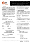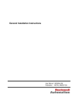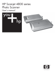
1
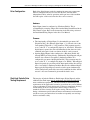
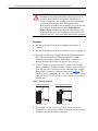
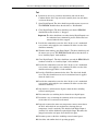
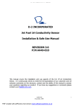
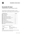
Service Bulletin
Instructions for ATEX Approved Drives in
Group II Category (2) G D Applications with
ATEX Approved Motors
General
This document provides information on operation of an ATEX Approved drive
and ATEX approved motor. The motor is located in a defined hazardous
environment, while the drive is not. A protective system is required to stop
current flow to the motor when an over temperature condition has been sensed
in the motor. When sensed, the drive will go into a fault stop condition.
The drive is manufactured under the guidelines of the ATEX directive 94/9/EC.
These Drives are in Group II Category (2) GD Applications with ATEX
Approved Motors. Certification of the drive for the ATEX group and category
on its nameplate requires installation, operation, and maintenance according to
this document and to the requirements found in the User Manual and
appropriate Motor Instruction Manual(s).
!
Motor Requirements
ATTENTION: Operation of this ATEX certified drive with an
ATEX certified motor that is located in a hazardous environment
requires additional installation, operation, and maintenance
procedures beyond those stated in the standard user manual.
Equipment damage and/or personal injury may result if all
additional instructions in this document are not observed
• The motor must be manufactured under the guidelines of the ATEX directive
94/9/EC. It must be installed, operated, and maintained per the motor
manufacturer supplied instructions.
• Only motors with nameplates marked for use on an inverter power source,
and labeled for specific hazardous areas, may be used in hazardous areas on
inverter (variable frequency) power.
• When the motor is indicated for ATEX Group II Category 2 for use in gas
environments (Category 2G) the motor must be of flameproof construction,
EEx d (according to EN50018) or Ex d (according to EN60079-1 or
IEC60079-1). Group II motors are marked with a temperature or a
temperature code.
• When the motor is indicated for ATEX Group II Category 2 for use in dust
environments (Category 2D) the motor must be protected by an enclosure
(according to EN50281-1-1 or according to IEC61241-1: Ex tD). Group II
motors are marked with a temperature.
2
Instructions for ATEX Approved Drives in Group II Category (2) G D Applications with ATEX Approved Motors
• The motor over temperature signal supplied to the drive must be a
normally closed contact (open during over temperature condition)
compatible with the drive’s digital (logic) input circuitry. If multiple
sensors are required in the motor, the connection at the drive must be the
resultant of all required contacts wired in series. Note that the drives are
available with either 24V DC or 115V AC input circuitry. Refer to the
drive User Manual for details.
• Refer to all product markings for additional cautions that may apply.
• Typical motor markings are contained on a motor certification nameplate
similar to Figure 1.
Figure 1 Sample Motor Nameplate
FLAMEPROOF Exd ENCLOSURE
EExd I/IIB
Tamb
C to
II 2 G/D
I M2
Sira
C
0518
ATEX
MFG. BY ROCKWELL AUTOMATION
Drive Wiring
Important: ATEX certification of this drive requires that 2 separate digital
(logic) inputs be configured to monitor a normally closed over
temperature contact (or multiple contacts wired in series)
presented to the drive from the motor.
The first input must be “Digital Input6/Hardware Enable” (terminal 32).
The second can be any other unused digital input between 1 and 5. Note that
all inputs are typically supplied in a “default” configuration to a function
such as Start and Stop. This may influence the input selected by the user for
this function. The following examples will assume Digital Input 5 (terminal
31) is being used as the additional required input. The 2 input terminals
must be wired in “parallel” (jumper is acceptable) so each is monitoring the
over temperature contacts. Digital signal inputs are wired with respect to the
digital input common. Refer to the drive User Manual regarding setup for
either internal or external 24V DC or external 115V AC logic power,
depending on the type that is supplied in your drive. Motor supplied
contacts must have ratings compatible with the drive’s input circuit ratings
and applied voltage level.
Figure 2 Wiring Example
External Power Supply
Neutral/
Common
115V/
+24V *
Internal 24V Power Supply **
25
Digital In Common
24 +24V DC
25 Digital In Common
26
Motor
Over Temperature
Sensor(s)
31
Motor
Over Temperature
Sensor(s)
31
32
Digital Input 6
32
Digital Input 6
* Voltage is Board Dependent
** Not available with 115V I/O
Instructions for ATEX Approved Drives in Group II Category (2) G D Applications with ATEX Approved Motors
Drive Configuration
3
Both of the digital inputs required to monitor for motor over temperature
must be configured correctly to assure that the drive will shut down
independent of drive software operation, and be put into a fault condition
that will require a fault reset before the drive can be restarted.
Hardware
Digital Input 6 must be configured as a Hardware Enable. This is
accomplished by removing Jumper J10 from the Main Control Board in the
I/O Control Cassette. Refer to the instructions in the I/O wiring section of
the Installation/Wiring Chapter in the drive User Manual.
Firmware
• The functionality of Digital Input 5 is determined by parameter 365
[Digital In5 Sel]. (If a different digital input “x” is selected, refer to the
corresponding [Digital In “x” Sel] parameter.) This parameter must be
set to a value of “3” to configure this input as an “Aux Fault.” When this
digital input is opened, the drive will immediately shut down in a fault
condition and require a fault reset before the drive can be restarted.
• Opening Digital Input 6 when configured as a Hardware Enable will
interrupt IGBT gate firing directly. Additionally, Digital Input 6 will put
the drive into a normal “not-enabled” shutdown condition. It is
configured by parameter 366 [Digital In6 Sel]. This parameter must be
set to a value of “1” to configure this input as an “Enable.” When Digital
Input 6 is opened, the gate firing will be interrupted and the drive will go
into a “not-enabled” shutdown condition. Because the additional digital
Input (typically Digital Input 5) must be wired to open simultaneously
and be configured to put the drive into a fault condition, the drive will not
restart if a new start command is given until the fault is reset.
Start-Up & Periodic Drive
Testing Requirement
The integrity of both the Hardware Enable input (Digital Input 6) and the
additional Aux Fault input must be maintained and verified periodically to
meet certification requirements. The interval must be determined by the
requirements of the application, but not be greater than one year. In addition
to any requirements to check the integrity of the over temperature device(s)
and the wiring of the over temperature contact closure to the drive
terminals, the drive circuitry itself requires testing. This must be done
during a maintenance period when the motor environment is not hazardous
and all necessary precautions have been taken to repeatedly start and stop
the drive and motor safely.
4
Instructions for ATEX Approved Drives in Group II Category (2) G D Applications with ATEX Approved Motors
!
ATTENTION: Power must be applied to the drive to perform
the following procedure. Some of the voltages present are at
incoming line potential. To avoid electric shock hazard or
damage to equipment, only qualified service personnel should
perform the following procedure. Thoroughly read and
understand the procedure before beginning. If an event does not
occur while performing this procedure, Do Not Proceed.
Remove Power including user supplied control voltages. User
supplied voltages may exist even when main AC power is not
applied to then drive. Correct the malfunction before continuing.
Preparation
1. Disconnect all power from the drive including control power, if
supplied.
2. Disconnect the motor from the driven load if necessary, to run this test.
3. Disconnect the motor over temperature contact connections from the
drive. This includes both Digital Input 6 (terminal 32) and the
additional required input (typically Digital Input 5, terminal 31).
Remove the jumper between the two inputs if one is in place.
4. Connect a means to open and close a N.C. contact between Digital
Input 6 (terminal 32) and input common. Connect a separate means to
open and close a N.C. contact between the additional input (typically
Digital Input 5, terminal 31) and input common (see Figure 3). The
switching devices (pushbutton, relay, etc.) must have contacts rated for
either the 24V DC or 115V AC input circuit, whichever was supplied
with the drive.
Figure 3 Example Test Circuit
External Power Supply
Neutral/
Common
115V/
+24V *
25
Internal 24V Power Supply **
24 +24V DC
25 Digital In Common
26
31
32
Digital Input 6
* Voltage is Board Dependent
32
Digital Input 6
** Not available with 115V I/O
5. Be sure both sets of test contacts are closed. Assure all control
connections are properly made to the drive. Reapply power to the drive
including external control power, if supplied.
Instructions for ATEX Approved Drives in Group II Category (2) G D Applications with ATEX Approved Motors
5
Test
6. Perform any necessary parameter adjustments and start the drive.
Confirm that the drive stops and starts normally, then start and slowly
accelerate the motor.
7. Open Digital Input 6. The drive should stop and the motor coast to rest.
The HIM/OIM should indicate that the drive is “Not Enabled.”
8. Close Digital Input 6. The drive should not start but the HIM/OIM
should indicate that the drive is “Stopped.”
Important: The drive should not start when closing Digital Input 6 even
if a maintained start command is present and had not been
removed when the drive stopped.
9. Provide the command to restart the drive. In the case of a maintained
start, remove and reapply the start command. In either case the drive
should run normally.
10. With the motor running, open Digital Input 5. The drive should stop and
the motor coast to rest. The HIM/OIM should indicate that the drive is
in an “Auxiliary Input” fault condition.
11. Close Digital Input 5. The drive should not start and the HIM/OIM will
continue to indicate an “Auxiliary Input” fault condition.
12. Provide the command to restart the drive. In the case of a maintained
start, remove and reapply the start command. In either case the drive
should remain stopped and in a fault condition.
13. Provide a Fault Reset command to the drive. The drive fault should
clear. The drive should not start even if a maintained start is applied
when the fault is reset.
14. Provide the command to restart the drive. In the case of a maintained
start, remove and reapply the start command. In either case the drive
should run normally.
15. Stop the drive, and disconnect all power from the drive including
external control power.
16. Disconnect the test switching devices from the two digital inputs.
17. Determine a way to interrupt the continuity of the over temperature
circuit when it is reconnected to the motor.
18. Properly reconnect the motor over temperature contact connection to
the drive and include the test mechanism to interrupt the over
temperature circuit’s continuity. This includes both Digital Input 6
(terminal 32) and the additional required digital input. Reconnect the
jumper between the two inputs if one had been in place.
19. Reconnect power to the drive including external control power.
20. Start drive and confirm that it is operating properly.
6
Instructions for ATEX Approved Drives in Group II Category (2) G D Applications with ATEX Approved Motors
21. Interrupt the continuity of the over temperature circuit connected to the
drive. The drive should stop and the motor coast to rest. The HIM/OIM
should indicate that the drive is in an Auxiliary Input fault condition.
22. Remake continuity of the over temperature circuit connected to the
drive’s digital inputs. The drive should remain stopped and in an
Auxiliary Input fault condition.
23. Provide the command to restart the drive. In the case of a maintained
start, remove and reapply the start command. The drive should remain
stopped and in an Auxiliary Input fault condition.
24. Provide a fault reset command to the drive. The drive fault should clear
but the drive should not restart.
25. Provide the command to restart the drive. The drive should run
normally.
26. Stop the drive and disconnect all power including external control
power.
27. Remove the test mechanism, reconnect original wires and verify all
wiring.
28. Reconnect the motor to the load if it had been previously disconnected.
29. Check for proper operation.
Instructions for ATEX Approved Drives in Group II Category (2) G D Applications with ATEX Approved Motors
Notes:
7
*366659P01*
www.rockwellautomation.com
Corporate Headquarters
Rockwell Automation, 777 East Wisconsin Avenue, Suite 1400, Milwaukee, WI, 53202-5302 USA, Tel: (1) 414.212.5200, Fax: (1) 414.212.5201
Headquarters for Allen-Bradley Products, Rockwell Software Products and Global Manufacturing Solutions
Americas: Rockwell Automation, 1201 South Second Street, Milwaukee, WI 53204-2496 USA, Tel: (1) 414.382.2000, Fax: (1) 414.382.4444
Europe/Middle East/Africa: Rockwell Automation SA/NV, Vorstlaan/Boulevard du Souverain 36, 1170 Brussels, Belgium, Tel: (32) 2 663 0600, Fax: (32) 2 663 0640
Asia Pacific: Rockwell Automation, Level 14, Core F, Cyberport 3, 100 Cyberport Road, Hong Kong, Tel: (852) 2887 4788, Fax: (852) 2508 1846
Headquarters for Dodge and Reliance Electric Products
Americas: Rockwell Automation, 6040 Ponders Court, Greenville, SC 29615-4617 USA, Tel: (1) 864.297.4800, Fax: (1) 864.281.2433
Europe/Middle East/Africa: Rockwell Automation, Herman-Heinrich-Gossen-Strasse 3, 50858 Köln, Germany, Tel: 49 (0) 2234 379410, Fax: 49 (0) 2234 3794164
Asia Pacific: Rockwell Automation, 55 Newton Road, #11-01/02 Revenue House, Singapore 307987, Tel: (65) 6356-9077, Fax: (65) 6356-9011
U.S. Allen-Bradley Drives Technical Support
Tel: (1) 262.512.8176, Fax: (1) 262.512.2222, Email: [email protected], Online: www.ab.com/support/abdrives
U.S. Reliance Drives Technical Support
Tel: (1) 800.726.8112, Online: www.reliance.com/prodserv/standriv/customer
Publication RA-SB001A-EN-P – February, 2005
P/N 366659-P01
Copyright © 2005 Rockwell Automation, Inc. All rights reserved. Printed in USA.