1
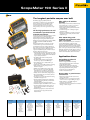
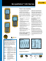
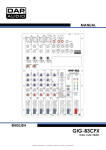
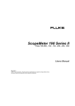
ScopeMeter® Test Tools
ScopeMeter portable oscilloscopes take you into territory standard
bench scopes can’t go: where it’s harsh, hazardous and dirty – without
sacrificing any capabilities. They provide you with unmatched speed,
performance and analysis power while working on site.
76
ScopeMeter 190 Series II
New
The toughest portable scopes ever built
What could you do with four
channels?
Combining rugged portability with the
performance of a bench scope, the Fluke 190
Series can take you from troubleshooting
microelectronics all the way into power
electronic applications. See more, fix more
and go where you’ve never gone with a scope
before.
The first high-performance two and
four Channel scopes built for harsh
industrial environments.
Introducing the first high-performance portable
oscilloscopes with 2 or 4 independently
insulated input channels, an IP51 dust- and
drip waterproof rating and a CAT III 1000 V /
CAT IV 600 V safety rating. Choose from 500 MHz,
200 MHz, 100 MHz or 60 MHz bandwidth
models.
Now plant maintenance engineers can take
a four-channel scope into the harsh world
of industrial electronics. Safely troubleshoot
three-phase systems like variable speed drives,
UPS or back-up generators. Measure input,
output and feedback signals simultaneously to
diagnose industrial electronics.
• 4 independent isolated input channels enable
3-axis industrial testing, simultaneous testing
of input signals, output signals and feedback
loops or safety interlocks
• 190-XX4 model with four independent
isolated inputs
• 190-XX2 models with two independenet
isolated scope inputs and DMM input
• Fast sample rate: up to 5 GS/s with up to
200 ps resolution
• Single shot, pulse width and video triggering
• Deep memory: 10,000 points per trace
waveform capture
• CAT III 1000 V / CAT IV 600 V, safety rated
• Up to seven hours of operation with high
performance Li-ion batteries, that extend
usage time plus optional external charger
• Battery door for conveniently swapping out
• Two isolated USB ports, for memory devices
and PC connectivity
• Security slot to lock down instrument using
standard Kensington® lock
• Connect & View™ triggering for intelligent,
automatic triggering on fast, slow and even
complex signals
• Frequency Spectrum using FFT analysis
• Automatic capture and REPLAY of 100 screens
• ScopeRecord™ mode gives 30000 points or
more per input channel for low frequency
signal analysis
• TrendPlot™ paperless recorder mode with
deep memory for long-term automatic
measurements
Technologies
Equipment
Take multiple measurements simultaneously
to track down the root cause of your most
complex troubleshooting challenges.
• Easily diagnose timing-related issues with
multiple signals
• Real-time inspection of multiple signals
simultaneously
• Meaure a combination of input and output
signals and system safety interlocks and
feedback loops
Fluke 190-502 brings wide
bandwidth test applications in the
palm of your hand!
With the new 500 MHz model, the verification
of telecommunication equipment, high
frequency and wide bandwidth systems such
as radar equipment has become truly portable.
Conveniently verify the systems performance
right ‘on the spot’, fully safely without carrying
bulky lab equipment around. Battery powered
and fully floating – up to 600V CAT III, for each
channel and in between channel references.
Application driven
Find problems in industrial
systems including:
• Circuit voltage/current overloading
• Attenuation/input impedance mismatch
• Signal fluctuation/drift
• Conditioning circuits signal integrity
• Test point verification for critical signals
• Input/output/feedback timing issues
• Induced noise and disturbances
• Random shutdowns/reset
Diagnose VSDs* or power inverters
and converters
• Harmonics, transients and loads in three
phase power input
• Troubleshoot dc to ac converters for faulty
control circuits or output IGBT gate stages
• Cable interface - test PWM output for
reflections and transients
• Vpwm measurement to measure the effective
voltage on drive outputs
Electrical
Electromechanical
Process Controls
Automation
Medical Imaging
Avionics
Switch Gear,
Interlocks,
Motors,
Pumps,
Fans,
Furnaces,
Presses,
Mixers,
Refrigeration
Actuators,
VFD Drives,
Linear Motors,
Pressure-LevelFlow-Position
Sensors,
Packaging
Equipment
Transducers,
Sensors,
Loop Controllers,
Calibrated Gauges
PLC´s,
Sensors,
Transducers,
Motion
Controllers,
Rotory
Encoders,
Scanners,
Readers,
Printers
XRay,
MRI,
Ultrasound
Imaging
equipment
Flight Line
Navigation
Systems,
Communication
systems,
Radar,
On board
aircraft control
systems
A/V & Security
Systems
Retail security
devices,
Surveillance and
monitoring
equipment,
RFID
77
ScopeMeter 190 Series II
New
Multiply your diagnostic powers with the new
Fluke 190 Series II portable oscilloscopes
Rated all the way to CAT IV
ScopeMeter test tools are rugged solutions built for industrial troubleshooting. The
new Fluke 190 Series II are double-insulated floating oscilloscopes safety rated for
measurements up to CAT III 1000 V/CAT IV 600 V environments. The new 500 MHz
model is rated all the way up to 600 V CAT III.
Measure from mV to kV safely
Independently isolated inputs allow you to make measurements in mixed circuits
having different ground references reducing the risk of accidental short circuits.
Conventional bench oscilloscopes without special differential probes and isolation
transformers can only reference measurements to line power earth ground. With
standard probes that cover a wide application range from mV to kV, you are ready for
anything from micro-electronics to heavy-duty higher voltage electrical applications.
Fluke 190-204
IP-51 rated for harsh environments
Rugged and shock-proof, ScopeMeter portable oscilloscopes are built for dirty,
hazardous environments. With its sealed case, it can endure dust, drips, humidity and
airborne pollutants. Every time you reach for ScopeMeter you can be confident it will
work reliably wherever your work takes you.
USB connectivity makes it
easy to capture and share
waveforms
Fluke 190-202
True RMS
Optional Accessories
C290 HH290 SCC290 VPS410-R VPS410-G VPS410-B VPS410-V VPS420-R BC190 EBC290 TL175 BP290 BP291 SW90W VPS510-X 78
Hard shell protective carrying case for 190 Series II
Hanging Hook for 190 Series II instruments
FlukeView Software (full version) and C290 Carrying Case kit
Voltage Probe set, 10:1, 300 MHz,
one set red
Voltage Probe set, 10:1, 300 MHz,
one set grey
Voltage Probe set, 10:1, 300 MHz,
one set blue
Voltage Probe set, 10:1, 300 MHz,
one set green
High working voltage probe set 150 MHz,
100:1, CAT III 2000 V (1000 V to earth)
Mains adapter/battery charger
External battery charger for BP290
and BP291
TwistGuard™ safety designed Test Leads set (1 red, 1 black)
Li-Ion battery pack, 2400 mAh
Li-Ion battery pack, 4800 mAh
FlukeView® ScopeMeter Software for Windows®
Wide bandwidth probe set, 10:1,
500 MHz, 600V CAT III
The new Fluke 190 Series II offers two USB ports,
electrically isolated from measurement input circuits.
Easily transfer data to a PC. Archive and share
waveforms with OEMs, colleagues and support staff.
Store waveforms, screen captures and instrument
setups onto USB memory devices.
FlukeView ScopeMeter software for
documenting, archiving and analysis
Get more out of your ScopeMeter with FlukeView® ScopeMeter® SW90W Software for
Windows.
•Documentation—transfer waveforms, screens and data to your PC for printing or
importing data into a report
•Add text to ScopeMeter settings—give operators guidance when recalling settings
•Archive—create a library of waveforms for easy reference, waveform comparison, or
pass/fail testing
•Analysis—use cursors, perform spectrum analysis or export data to another
analysis program
ScopeMeter 190 Series II
p
lic
at
io
n
N
o
Connect-and-View™ triggering for an instant,
stable display
te
g
fyin
on
No
te
n
A
sti aliesel
plic
io il
Ap
my
is
at a
hann
De anom
eing
ope
ic s/F ke II
2-C
Connect
the ScopeMeter
se
tly,
t
e Series IIoscillosctest tool ande ap
un s lu s
ty ou l.
the
ali
le
or view
0
driv
m Pa a F rie
ction Voge cut
?M
ris
e 19 portab
rk
ng
of funevery
result: the
start
of
Ch
wo mm
s
it’s
Fluuk
nce
lievi
er.
co
s his
nt,
o ing ith Se
t ou
be g.
theroeM
no aletds
las uipme gel ha for the pical
is
measurement
in
c
g
o
c
ery
ch pti eth lse
eing tand ing ev test eq ies, Vorunning a’s tro90 °F
usin Scynop
le us w 0
u
rid
O
Se ders
t
S us t m p pe
n wr ctronic chnolog ms in Flo nstop
jus
ca
o
s
ste
U
un
s
t’s
te nt ing 19
sy mers
a no te IT sc rm ”
ly no d tha mens le
AC
ing ns If anyonece of eleilding Te
ing
ch ro rd rd illo o ils
g e st er
g ro
Bu ing HV ial custoseem els. An at Sie
su nch da da osc perf “fa
Test
pin
a pie ns
tio
n
ns
ep
lev
by
n
ee
of
n
s
erc
i
y,
me
y
y
t
m e
ke
d
dit
Sie
m S sta sta ble to 100
hnicia re sw icienc d
Func e
At for him commmarke humi
tec
st ip t e
a ed to
ste the e e
ge service
s It frequently
is
a mo and
t
y eff ss, an er
by
are%automatically
detected
that
ouhappens
ich d 95
sy d quir t th port us p
ed plays energ
’s lar wh
Ca dyengineers
n
u
fac followed
adjusted,
by displayhave
of
acceice tow
g
Te qu ask eM
panyto spend
on a re ins II be g
er, a lot
s an ges which
off
n
a s n
rized orratio
ath measuring
Stu time adjusting
ing the signalsu
inrin
the correct
their
ati e a
e
p
we peraturechallen ies, s: en autho
ic rop ric ag rie ca tori
respect un
to the horizontal
device such as a portable
oscil- logwith es
ilding
un Eu me d Se at f s
m co
the
no
tem
cc
st
bu
m in
and vertical
loscope for an optimal
il ch rs’ su
ain axis.
e of setting.
A ste 0 th o
l
ery At least 1.5
aTe
e
onspent
h te r 19 n ble
ing
/f
om )
me rt tto
4ag
periodsev
of the signal are
Valuable time is
completing
ne o
S
e
ction d for rs.
of tim
Buildsscusto po ee
l c DH ort re te tio pa
an tw
th
p
ati
®
Application Note
®
ex
un
before the pattern is
ote measured
this set up, and ideally,
could
a thispr
N a e nc a
me
h
ita (S
pits
slice Vogel, to
n shar-bero
sto
c
in als eM fu
-c g ks een ial the shown.
be done automatically.
ort,ca ad
le
ein
s
ga
m cu
dig hy )
is
il
yre yecanit by
le sin s
or
th comf weof
orin rtant, say n be abms by
s rc ET ign op a t
fet
With the introduction
spthe
ip u ma betwcoax atch sym ial e
Stprovides
eto ef Connect and View
g s firewsa
icia
the
ay ra N l s Sc ss/f en
d
ble
a II,
at av
reliable and repeatin late 190
ult ng t ed a m Ω ax th k. new ScopeMeter
impo techn D pro from A
ie Series
pl w a stable,
to ste
ad Hie (SO ica ke pa um
r
n, itrevamped
It’s any
M sti ren us and e to 120 Ω co ut of mas IIFluke has
VF
m a
se: en
fo e-display
intru
the
orm
p ukeVenits
icia
of virtually
unique
tr
tr lu
te g
ow al
eable
om
Ed m
that terize wavef premi g wh
m
te iffe n is nel lin e 75 tp ific ries feature,
cr hn
en disment
N igit ork lec e F ard ins .
at tec
ul
rac anda
motor drive
Connect
or View.
lin
itin
His
s frincluding
ou
te h Fl efand
d r
lu
m st
plACsignal,
d
on th
beized
ve. re tel view
HV
stomed difm wh
D etw e e Th nd he sis
it know
invfoest ®withoutcha
turingg Hdri
ba pa si of a d ec Se si teScope users
.
signals,
touchan m
n control
or an
cu how
mo
W wav
tr
cap
,
g, ter
A tch is nce e to t an s sp 190 can /fail e
by gel
N Th ks. sta . T aly
efurnaaton
l. ,ceeste en
dinSD
caerg
a dbe.
is ch
veform tsite changes
in Me Signal
ing
button.
triggering
VoceWrong
a dcan
g av
a sts an
ret
pa ansm da l lin pu it er es ss ficult
rmSco
th
ard
offen are
n
isD mu a wa tic volhas a
d
uspee large lete Exbe
com
/s
w instantly
as
fold m
re stginthe
nal ted in
k
recognized
and
settings
. II
showan
unstable
and
, sta nal
tr pe ca e in has et op pa ofsettings
ub
Mb Ω sig
ea
s
nd igi- e an tal
g
he
on
m ers e te er
g
fe
2 75
sin
n nd
te viha
cr results.
ut rieks ol er wrong
orat for,
d tro
sen a single e sig may loojust
im etri Th ch eM sc m a tpSe
in recuslFluke’s
.csvadjusted
once
again,
apre
stable
ef t or an
ed et
sta rd orvoic digi mdrives
off es rth
0 massometimes
us A /fin
ai his
in
statTo
ld
m e. ea op cillo or19ou
sa inol. “Ou
g. Th that
encyis rep
display.
This
all air
done autounique
Connect and View
th r fu
To wav
rf d r®t Te
than readin value but cou n or
monitfrequ
ls:
03 anda for er reco T) M l- lin lun e Sc too
ss by stiew
os pe
el
isol opeMake
en
ce
e
,
we
ete
Te
d
ov
g
ta
lev
pa
fo
.7
an
le
le
matically,
but
manual
overruling
recognizes
signal
patterns,
and
ba Thing ly eM
age
U CIT PC gi
ed eV ere
st ed
nce
tortio ntary
th
t ffer d Sc s m
in r,
iab nent- differen
G
un and
pe an
at ukwh
g
al
s- ak sets
ve
pu di g an e automatically
Scop
rtabl us
po possible.
is still
overcorrect
sha at a glave a dis mome be
e is a uc sion IT ly C the di
B
ol
asur
in ot varcom
the
paIfrtmanual
m eo lowup
Fl itsho
a
po ne
to ACpoing
air I the
neo in ith in Fluk
Th 03 introdsmis is anmer with ce toing to of Me
in an
right ily ha ” or
is/s needed,
ScopeMeter
rt to a host
triggering,
attenuator
know
al t andedtime
l, stHV
tsild of Mor
Ds), ruling
mean
ta the n w float ege
g Ch
h
Mb Ωrep
Bu
es ithou e
en risksettings.
2 00
bill. recently
.
as eas “edge, too shom, or s, would
190 $2
Series
from
on (VF
the often
th II te
G.7ally tran . It (for ed -voi rd idth ltin 2.” auto12 airwill switch
ug
at lu eris Vo
nsmbase
gh
gs ob wSwitching
a
ost
can een a rep
t th oscilloscope
e
we
nario
n ta orks on ciat og acco dw su ro T1
ba Ch
Th of riesmesure ScopeMeter
matic0 to 1/2 automatic,
which isrou ke alm r probleomalie th just
th ndin pr tsportable
ou tial
betw 00,00 cause very sceuses his
n ), re . Th a
da etw dati so nal n
he
tto
ator: forts Sie
wi
l an
spi
en
ithge
Eit
nal.
be
pe
visible
on
the
display.
correct
signal
patterns
nce men
t
,
na
$1
oudisplay
lta
ble
n.
n en as . A rsio a ba m .703 s in Oper nicianinpu 0 Se mea hou gr
er
a
w ff
nd
tha Vogel illosco , see er sig
h
ha the sig to
da red vo
l ted 1 gives
Figure
an
couple
of seconds, firsthatcne
m at’s rd nve es 0 pp r G sult of Tech
di
19 ese wit d only
Ds,
oscexample
pe takes
an andator
logies
ics
blems of of othr y istinguis g of
su
me m a
Pa en
ble of pro
al
th anda co ir 10 fo re E1
im nt
din
th ble ante rre
thelar
different
types
waveforms
ge VF rta
is exactly
what an
Pa
eathisefac
rist chno
docum
r aind ric rea allowsand fro ves
h and
/s
po
mwelinr tern
and e.
be
st ta requ (± it is d
teTe e
tanceps, by
si ts:
On
w Cu
ig operator
ter
Mb Ω
which
can deacidetected
e wa
ac ar on
2 0
i b me scope on,
gat
da M /s c un g th an
, ctpothe exwants.
un e hsisre
sha
12
peMe er&cap
ar es ti a inemen
Connect
View.
If srequired
the/ l nu “The ormatirces—sinputs of d,
Settings
on a basiPC 4 kb si in b/s
Sco
g r an regarding
th r di in
ng migh
ch rfac da r nur
inf sou
analy
• AC/DC
m
uncov for
out
r firibest
e—an
6 e ba plex M s.
r iscano ,”
settings
be
al te en s fo as
ord coupling
fo ad • foamplitude,
tocriteria
of
ow form
and voltag parirec
-throunsisto itch
e
Glitch
nsisto edby
th ulti 44 b/ tric k in mm itMe
lo ee•d timebase,
sh ve
optimized
switchingswon
mberdetect
tra
onge
. c onedor • nu
e.
inputs t and ke com e so
m 1.5 8 M elec or co lim ewa
n blerse, a tra -fast ba
n obtriggering,
e ck ansed, Figure
ph
eveofcou
tag
all
the following
le an
•
ing options:
2 shows
the
different
tor
k
of .04 e etw in re gnal al ar
on the
r, ma
pr
currentte
Te ch
ues and clo to
d vol r fac
itch
lightn
Ds,
Ex
l
2 Th e n d si gn
Automatic
trigger
an
• “Of
• etc.
settings.
ma
a
we
sw
t
s,
VF
rt
t
f en
ren
a po
tha
th be e si
cally s. “It een. op mes sta happen
for of cur rive
say tw w eti
t
of scri 3. Th b/s
s
de
30
k he
be w som en tha weird
N
son I can
or
de .70 8 M .
t.”
tw
w
ISD
forth it can
1
d
ing
. Wh
circui
G .04
that
ne
the
and@ down start dole, at loa
30
2 gure
for
ak
ll
DN
Fi
IS
r ybre tors wi examp ly see and
2.
re
r a mo ngs. For’ll actual back which
gu
thi
Fi
we bangingt sure
ib
y
L
ar
stagemotor is no
br
l
i
it
l
if
/
a
the as
m
n.”
it
forth to tur
.co
ig
ke
way
D
flu
re
gu
Fi
1.
03
G7
- E1
e
at
pl
m
te
F
ro
Figure 1.
m
Fr
th
om
e
F
lu
th
e
k
e
Flu
ke
Di
git
al
Lib
ra
ry
@
ww
w.
If you’ve used other scopes, you know how tricky
triggering can be. If settings are incorrect, results
can be unstable or incorrect. Connect-andView™ automatically sets up correct triggering
by recognizing signal patterns. Without touching
a button, you get a stable, reliable and repeatable
display of virtually any signal including motor
drive and control signals. It’s especially fast and
convenient when you’re measuring a number of
test points in rapid succession.
Connect-and-View™ captures even the
most complex motor drive signals.
From the Fluke Digital Library @ www.fluke.com/library
A range of application notes is available.
See the Fluke website.
Included Accessories
Fluke 190 Series II 4-channel instruments include a set
of four probes, hanging strap, handstrap, USB cable with
mini-B connector, double capacity Li-ion battery BP291,
battery charger/power adapter BC190, a FlukeView demo
package and users manuals on CD-ROM. The /S-versions
also include the C290 hard-shell carrying case and the
FlukeView software package. The 2-channel models come
with two probes plus a set of TL175 test leads and a single
capacity battery BP290. The 190-502 also includes two
pieces TRM50 coaxial feedthrough terminator.
The SCC290 kit includes: C290 hardshell carrying case and
FlukeView® for Windows® software (full version).
Built-in digital multimeter (2 channel models)
190 Series II models with isolated dual input
scope and dedicated digital multimeter.
Conveniently switch from waveform analysis
to precise multimeter measurements using
the built in 5000 count digital multimeter.
Measurement functions include Vdc, Vac,
Vac+dc, resistance, continuity and diode test.
Measure current and temperature using suitable
shunt, probe or adapter with wide range of
scaling factors.
The built in multimeter provides
convenient precision measurements.
Ordering Information
Fluke-190-502/S Fluke-190-204/S Fluke-190-204 Fluke-190-202/S Fluke-190-202 Fluke-190-104/S Fluke-190-104 Fluke-190-062/S Fluke-190-062 AS400 BP291 BP290
C195 C290 EBC290 HH290
RS400 RS500
SCC290 SW90W TRM50
VPS410-x VPS420-R VPS510-x
Color ScopeMeter (500 MHz,
2 channel), with SCC290-kit
Color ScopeMeter (200 MHz,
4 channel), with SCC290-kit
Color ScopeMeter (200 MHz, 4 channel)
Color ScopeMeter (200 MHz,
2 channel), with SCC290-kit
Color ScopeMeter (200 MHz, 2 channel)
Color ScopeMeter (100 MHz,
4 channel), with SCC290-kit
Color ScopeMeter (100 MHz, 4 channel)
Color ScopeMeter (60 MHz,
2 channel), with SCC290-kit
Color ScopeMeter (60 MHz, 2 channel)
Probe Accessory Extension set for VPS400 Series probes
Double capacity Li-Ion battery
(4800 mAh) pack for 190C Series II
Single capacity Li-ion battery
(2400 mAh) pack for 190-series II
Soft padded carrying case for ScopeMeter and accessories
Protective Carrying Case for Fluke 190-series II
External Battery Charger for charging BP290 or BC291 outside the instrument
Hanging Hook
Probe Accessory Replacement set for VPS400 series probes
Probe Accessory Replacement set for VPS510 series probes
Software and Case kit for Fluke 190 Series 190 Series II. Includes SW90W and C290.
FlukeView® ScopeMeter Software for Windows® (full version)
Coaxial 50 Ω feedthrough terminator
Probe-set, 10:1, 1000V CAT III / 600V CAT IV (colors: blue, green, red, grey)
Probe-set, bicolor (r/b), 100:1, 150 MHz,
1000V CAT III / 600V CAT IV, working voltage (voltage between probe tip and reference lead): 2000V CAT III / 1200V CAT IV.
Wide bandwidth probeset, 500 MHz, 10:1, 600V CAT III
Automatic capture and replay op 100 screens
Scope users know how frustrating it is to see a onetime anomaly flash by, never to be seen again. Not
with the ScopeMeter 190-series! Now you can look
back in time with the touch of a button. In normal
use, the instrument continuously memorizes the
most recent 100 screens. At any moment in time, you
can ‘freeze’ these latest screens and scroll through
them picture-by-picture or replay them as a ‘live’
animation. Cursors and zoom can be used for further analysis. You can even use
the advanced trigger capabilities to capture up to 100 specific events. Two sets of 100
screens with individual time stamps can be stored for later recall or download to a PC.
See dynamic signal behavior instantly
The digital Persistence mode helps to find anomalies and to analyze complex
dynamic signals by showing the waveforms amplitude distribution over time using
multiple intensity levels and user selectable decay time – it’s as if you’re looking at
the display of an analog, real time oscilloscope! A fast display update rate reveals
signal changes instantaneously, useful for instance when making adjustments to a
system under test.
Recommended Accessories
SW90W
SCC290
VPS420-R
EBC290
AS400
79
ScopeMeter® 120 Series
Three-in-one simplicity
Fluke 125
Fluke 124
The compact ScopeMeter 120 Series
is the rugged solution for industrial
troubleshooting and installation
applications. It’s a truly integrated test
tool, with oscilloscope, multimeter and
“paperless” recorder in one affordable,
easy-to-use instrument. Find answers to
problems in machinery, instrumentation,
control and power systems quickly and
easily.
unique Connect-and-View recognizes
signal patterns, and automatically
sets up correct triggering. It provides a
stable, reliable and repeatable display
of virtually any signal - including
motordrive and control signals - without
touching a button. Signal changes
are instantly recognized and settings
adjusted for - once again - a stable
display.
•Dual-input 40 MHz or 20 MHz digital
oscilloscope
•Two 5,000 counts true-RMS digital
multimeters
•A dual-input TrendPlot™ recorder
•Bus Health Test for industrial bus
systems (Fluke 125)
•Connect-and-View™ trigger simplicity
for hands-off operation
•Power Measurements and Harmonics
measurement (Fluke 125)
•Shielded test leads for oscilloscope,
resistance and continuity
measurements
•Up to 7 hours battery operation
•600 V CAT III safety certified
•Optically isolated interface for PC and
Printer connection (optional)
•Rugged, compact case
Use TrendPlot™ to help find
intermittents fast
Connect-and-View™ triggering for
an instant, stable display
Fluke 123
Scope users know how difficult triggering
can be. Wrong settings show unstable
and sometimes wrong results. Fluke’s
The toughest faults to find are those
that happen only once in a while:
intermittents. They can be caused by
bad connections, dust, dirt, corrosion
or simply broken wiring or connectors.
You may not be around to see it – your
Fluke ScopeMeter will. In this “paperless
recorder” mode, you can plot the
minimum and maximum peak values
and average over time – up to 22 days
(Fluke 190 Series) or 16 days (Fluke 120
Series).
Bus Health mode (Fluke 125)
Bus Health mode gives a clear “Good/
Bad” indication for the electrical signals
on industrial buses and networks, such
as CAN-bus, Profi-bus, RS-232 and many
more. The Fluke 125 validates the quality
of the electrical signals as soon as any
electrical signals are passed along the
network.
True RMS
Included Accessories
PM 8907 line adapter/charger, STL120-III
shielded test leads set (1 red, 1 grey) including
hook clips, BB120 shielded BNC adapter,
BP120MH NiMH battery pack, VPS40-III wide
bandwidth Voltage Probe (Fluke 124/125),
TL175 Safe-guard testlead, i400s current
clamp (Fluke 125), Getting Started booklet,
user’s manual (cd-rom)
Ordering Information
80
Fluke 123 Fluke 123/S Fluke 124 Fluke 124/S Fluke 125 Fluke 125/S SCC120
OC4USB
PM9080
DP120
ITP120
SW90W
BHT190
Industrial ScopeMeter® (20MHz)
Industrial ScopeMeter® (20MHz)
+ SCC120 kit
Industrial ScopeMeter® (40MHz)
Industrial ScopeMeter® (40MHz)
+ SCC120 kit
Industrial ScopeMeter (40 MHz)
Industrial ScopeMeter (40 MHz) +
SCC120 kit
FlukeView® Software + OC4USB Cable + Carrying Case
USB Interface Cable
RS-232 Interface Cable
Differential Voltage Probe
Isolated Trigger Probe
FlukeView Software
Set of 3 break-out adapters (Fluke 125)
Connect-and-View captures even the most
complex motor drive signals.
Bus Health mode allows for an analysis of the
signal quality on an industrial network.
See page 85 for specifications.
Recommended Accessories
SCC120
C125
See page 124
DP120
See page 86
OC4USB
See page 86
SCC128
See page 125
ScopeMeterTest Tools
Fluke 225C/S Industrial Networks
and Bus Health Test
Built on the Fluke 190C-series, the 225C/S makes Bus Health
Test analysis on the electrical signals on an industrial bus
or network, giving a clear “Good”, “Weak” or “Bad” validation
of the relevant parameters, presented next to the actual
measurement value. The Fluke 225C/S can make the signal
quality validation as soon as electrical signals are passed
along the network, without looking at the data content. It finds
errors like improper cable connections, bad contacts, incorrect
grounding and missing or superfluous terminators.
Included Accessories
BHT190 Set of three break-out adapters for industrial networks
BC190 Mains adapter/Battery charger
BP190 NiMH battery pack (installed)
VPS210 Voltage probe sets (1 red, 1 grey)
TL175 SafeGuard(r) Testlead set
C190 Hard shell protective carrying case
OC4USB Optically insulated USB interface cable for PC connectivity
SW90W FlukeView software package
(full version)
Ordering Information
225C/S Color ScopeMeter (200 MHz,
2.5 GS/s) with Bus Health Test capabilities and SCC-kit.
Typical status overview of a bushealth measurement.
General ScopeMeter
Specifications
Model:
190-502
190-204
190-202
190-104
190-102
190-062
225C/S
125
124
123
Oscilloscope Specifications
Bandwidth
500 MHz
200 MHz
100 MHz
60 MHz
200 MHz
5 GS/s
2.5 GS/s
1.25 GS/s
625 MS/s
2.5 GS/s
Max. timebase speed
1 ns/div.
2 ns/div.
10 ns/div.
5 ns/div.
Inputs and digitizers
2 + Ext.Tr.
2 + Ext.Tr.
2 + Ext.Tr.
2 (+ Ext.Trig. Optional)
600 V
CAT III
-
Max. real time sample rate
Input sensitivity
Independently floating isolated inputs
Dedicated test capabilities
4
5 mV/div.
4 ns/div.
2 + Ext.Tr.
600 V
CAT III
4
2 + Ext.Tr.
1000 V CAT III,
600 V CAT IV
10 000 samples per trace
30 000 min/max pairs
8 ns peak detect at full timebase range
yes
-
yes
-
V/Hz ratio
-
V/Hz ratio
-
BP291
BP291
BP290
2.1 kg
2.2 kg
2.1 kg
20 MHz
25 MS/s
2 mV/div.
Max.record length
…. In Scope mode
…. In ScopeRecord mode
Glitch capture
True RMS multimeter built-in (5000 counts)
40 MHz
3000
27500
50 ns
10 ns/div.
512 min/max pairs per input
40 ns
yes
V/Hz ratio
20 ns/div.
dual 5000 counts DMM
Bus health test
-
General Specifications
Mains adapter/battery charger incl. (type)
Battery installed
BC 190
Size
Weight
Safety certified
BP291
PM8907
BP290
BP290
265 x 190 x70 mm
2.2 kg
1000 V CAT III / 600 V CAT IV
2.1 kg
BP190
BP120MH
**
232 x 115 x 50 mm
2 kg
1.2 kg
600 V CAT III
81
ScopeMeter® Accessories
VPS410-X
VPS420-R
ScopeMeter series
VPS510-x
STL120-III
190-series II
Description
VPS40-III
120-series
VPS410-x
VPS420-R
VPS510-x
STL120-III
VPS40-III
DP120
Voltage probe
Wide bandwidth
voltage probe
red, grey, blue, green
Shielded Test leads
Voltage probe
red + grey (1 set)
red, grey, blue, green
High working voltage
probe*
bicolor (red & black)
black
Differential Voltage
Probe
red + grey (1 set)
Attenuation
10:1
100:1
10:1
1:1
10:1
200:1 / 20:1
Bandwidth
300 MHz
150 MHz
500 MHz
12.5 MHz
40 MHz
20 MHz
1.2 m
1.2 m
1.2 m
1.2 m
1.2 m
1.5 m (2x)
Colors available
Length
Safety Rating CAT II
--
--
--
1000 V
1000 V
1000 V
Safety Rating CAT III
1000 V
1000 V*
300 V
600 V
600 V
600 V
Safety Rating CAT IV
600 V
600 V*
--
--
--
--
*High Working Voltage Probe is specified for working voltages (between probe tip and reference lead) up to 2000V in CAT III or 1200V in CAT IV environments. Reference lead voltage (between reference lead and earth ground): 1000V in CAT III, 600V in CAT IV. These specification applies only when used with Fluke 190-series II Test Tool.
PM9081
PM9091/9092
PM9091
Description
PM9092
Safety designed 50 Ω BNC Cable set
(1 red, 1 black, 1 grey)
1.5 m each
0.5 m each
Length
Safety Rating CAT III
RS400
RS400
AS400
PM9080
OC4USB
BP120MH
BP290
BP291
EBC290
TRM50
RS500
C437-II
RF-AM90
82
PM9082
300 V
600 V
AS400
BP291
PM9093
DP120
PM9081
PM9082
PM9093
Dual banana plug
(m) to female BNC
--
Dual banana jack
(f) to BNC plug (m)
--
BNC (m) to dual
BNC (f) ‘T-piece’
--
600 V
600 V
10:1
OC4USB
Probe Accessory Replacement set for VPS200 and VPS400 series probes
Accessory Extension set for VPS200 and VPS400 series probes
RS232 interface cable for 120-series
Optocoupler to USB interface cable for 120 series
Ni-MH battery pack for Fluke 120-series and Fluke 43B
Single capacity Li-ion battery pack for 190-series II
Double capacity Li-ion battery pack for 190-series II
External battery charger for BP290 and BP291
Coaxial 50 Ω feedthrough terminator
Probe Accessory Replacement set for VPS510 series probes
Hard shell protective carrying case with rollers for 190-II and 430-II
RF Detector and Demodulation probe
EBC290