1
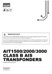
IMPORTANT NOTE The USB cable of the AIT3000 is designed to be used for configuring/programming the unit during installation and not for permanent connection to the boat’s Navigation PC. If you intend to permanently connect the AIT3000 to a PC or MAC via a USB interface, we recommend that you use our NMEA to USB adaptor cable which will protect the AIT3000 from voltage differences, noise and electrical spikes that can occur in marine installations. AIT3000 CLASS B AIS TRANSPONDER 1. Introduction Congratulations on the purchase of your AIT3000 Class B AIS Transponder. It is recommended that your transponder is installed by a professional installer. This Quick Start Guide will provide basic information on the AIT3000 to allow you to install and get the AIT3000 working. The full User Manual for the AIT3000 is available to download on the Support section of our website www.digitalyacht.co.uk 2. Before you start You will need the following items and tools to complete the installation: Class B AIS Transponder. Dedicated VHF antenna and cable – not supplied Dedicated GPS antenna and cable - supplied Access to 12V or 24v DC power supply where the unit is to be installed. Four M4 screws or other fixings appropriate to the mounting location. To configure the unit you will need: ® ® A PC running Microsoft Windows XP / Windows Vista / Windows 7 or Mac OSX with a free USB port. proAIS2 Class B AIS Transponder configuration software – Windows and Mac versions of software are supplied on the latest Digital Yacht CD-ROM or available for download from the www.digitalyacht.co.uk website. An MMSI number for your vessel Note: You can obtain an MMSI (Maritime Mobile Service Identity) from the same authority that issues ship radio licences in your area. An MMSI may have already been provided with your existing VHF radio licence. The MMSI number used for the AIS Transponder should be the same as that programmed into your VHF DSC radio. If you do not have an MMSI number the AIS Transponder will operate in receive only mode. Do not enter an invalid MMSI number. 3. Installation Before starting installation select a suitable location for the AIS Class B Transponder. The unit is water resistant; however it should be installed below deck in a dry location. When locating the unit you should consider: Routing of power and antenna cables to the unit. Provision of sufficient space behind the unit for cable connections. Routing of data connections to PC or chart plotter from the unit. Maintaining the compass safe distance of 0.5m. Visibility of the front panel indicators. Installation Step 1 - Antennas The AIT3000 has an integrated “Zero Loss” VHF antenna splitter that allows AIS reception/transmission through the boat’s existing VHF antenna. A PL259 to PL259 link cable is supplied to allow connection between the AIT3000 and your VHF radio. Disconnect the boat’s existing VHF antenna from the VHF radio and connect it to the VHF antenna connector on the AIT3000. Using the supplied PL259 link cable connect the VHF Radio Connector of the AIT3000 to your VHF radio. The VHF radio and the AIT3000 can both transmit and receive using the same antenna but they cannot transmit simultaneously, priority is always given to the VHF radio. Quick Start Guide for AIT3000 V1.00 TEL + 44 1179 554474 www.digitalyacht.co.uk [email protected] The supplied GPS antenna is designed to be fitted to a standard 1”x14 TPI threaded VHF pole mount, which are available in many different styles from all good marine electronic dealers and chandleries. You should ensure the GPS antenna has a good clear view of the entire sky. It is not recommended that the GPS antenna is mounted up a mast where the motion of the vessel will cause the antenna to swing and potentially reduce the accuracy of the GPS position. Do not mount your antenna in the direct path of a radar transmitter. Feed the ten metre long cable attached to the GPS antenna, through the pole and screw the antenna onto the pole mount as shown. Route the cable to your AIT3000 unit, adding any necessary extension cables. Connect the cable from the GPS antenna to the GPS connector on the AIT3000. The GPS antenna is terminated in a threaded TNC type connector. Installation Step 2 – Mechanical Fixings Access to the fixing holes is achieved by removal of the two green decal strips down each side of the AIT3000. Once fixed in place, the green decal strips can be clicked back in place. Secure the AIS Transponder to a flat surface in the selected location. Use four M4 wood screws or other fixings suited to the material the unit is being fixed to. The unit may be installed in any orientation Dimensioned Drawing 220mm 130mm Unit height = 55mm Quick Start Guide for AIT3000 V1.00 TEL + 44 1179 554474 www.digitalyacht.co.uk [email protected] Installation Step 3 - Power Provide power connections to the unit. Power is connected to the eight core PWR/DATA cable on the Red and Black wires. The Red wire is the positive (+) connection. The Black wire is the negative (-) connection. Connect the stripped wires to the nearest source of primary 12V or 24V DC power. Ensure that the supply is connected via the supplied 3A fuse or suitable circuit breaker. Add the fuse in the positive power connection to the unit if necessary. The AIT3000 Class B Transponder is designed for 12V or 24v DC systems. Installation Step 4 – NMEA 0183 The AIT3000 can be connected to other AIS compatible equipment via the NMEA0183 connections on the PWR/DATA cable, via the NMEA 2000 interface cable and/or to a PC via the USB interface. A table showing what each of the 12 wires of the PWR/DATA cable does is printed on the AIT3000 Transponder and repeated below for your convenience; Wire colour RED BLACK BLUE WHITE ORANGE BROWN TURQUOISE GREY PINK VIOLET YELLOW GREEN Description Power in + Power in Switch inputSwitch input+ NMEA0183 port 1 TX+ NMEA0183 port 1 TXNMEA0183 port 1 RX+ NMEA0183 port 1 RXNMEA0183 port 2 TX+ NMEA0183 port 2 TXNMEA0183 port 2 RX+ NMEA0183 port 2 RX- Function Power supply connections External switch connection for silent mode High speed NMEA0183 output (38,400 baud) intended for connection to chart plotters High speed NMEA0183 input (38,400 baud) Not normally used Low speed NMEA0183 Output (4,800baud) intended for connection to other NMEA0183 devices requiring a GPS feed. Note AIS data is not available on this output. Low speed NMEA0183 input (4,800baud) intended for connection to other NMEA0183 compatible sensors for multiplexing of data to the chart plotter The most common connection to a dedicated chart plotter is to take the NMEA Output 1 (Orange+ and Brown –) from the AIT3000 Transponder and to connect it to a free NMEA Input on the plotter. You must then tell the chart plotter that AIS data is connected to this port and set the baud rate to 38,400 Baud – the standard speed for AIS data. Consult the instruction manual supplied with your Chart Plotter to understand how this is configured. The AIT3000 has a second NMEA 0183 output that can be used to pass GPS data to a VHF radio or instrument system. NMEA Output 2 transmits GPS data at 4800 baud – RMC, GGA and GGL sentences. NMEA 0183 data from other equipment can be connected to either of the NMEA Inputs of the AIT3000, although this is most commonly connected to NMEA Input 2 (Yellow+ and Green-) at the normal 4800 baud rate for NMEA 0183. This data is then multiplexed with the AIS data and output on the NMEA Output 1 at 38,400 baud and also on the USB – useful when connecting to equipment that only has one NMEA input. Quick Start Guide for AIT3000 V1.00 TEL + 44 1179 554474 www.digitalyacht.co.uk [email protected] Installation Step 5 – N2Net (NMEA2000) The AIT3000 also has an N2Net connection which is Digital Yacht’s NMEA2000 compliant interface. To connect to other NMEA2000 products, simply find or add a spare NMEA2000 “T” piece on the existing NMEA2000 network and connect the AIT3000 N2Net connector to the “T” piece. The N2Net cable is just over 1m long and is terminated in an NMEA2000 Micro Male Connector. The AIT3000 does not take any power from the NMEA2000 network The AIT3000 outputs AIS and GPS data on to the network. All currently (Jan 2015) defined AIS PGNs are transmitted including those for Class B Static Data, AIS Sarts and AIS AtoNs, which some chart plotters do not support. The AIT3000 transmits the NMEA2000 Fast Update PGNs for GPS data and these are not compatible with all models of chart plotter so please check if the equipment on the NMEA2000 network will receive this data correctly. It should also be noted that the AIT3000 does not convert any of the NMEA0183 data that it receives in to NMEA2000 data. Installation Step 6 – USB Interface The USB cable of the AIT3000 is designed to be used for configuring/programming the unit during installation and not for permanent connection to the boat’s Navigation PC. If you intend to permanently connect the AIT3000 to a PC or MAC via a USB interface, we recommend that you use one of our NMEA to USB adaptor cables (P/No ZDIGUSBNMEA) which will protect the AIT3000 from voltage differences, noise and electrical spikes that can occur in marine installations. When connected to a PC or MAC via the USB cable, the AIT3000 will only get enough power from the computer to power the microprocessor and the AIS receiver. This allows you to program the MMSI number and other static data at home or in the office prior to installation. The AIT3000 will not transmit or get a valid GPS position fix when only powered from the USB interface and the RED Status LED will always be lit when powered from the USB cable. If you need to extend the USB cable, please use a USB extension cable that is no more than 4m in length. The maximum length of USB cable without the use of a powered extender cable or Hub is 5m. Please do not plug in the USB cable of the AIT3000 to your PC at this stage. We will cover this in section 4 Configuration. Installation Step 7 – Remote Switch To connect a remote “Silent” switch that allows you to turn on/off the transmission of your own vessels position (good etiquette when moored or in congested but safe conditions), you will need a conventional toggle type switch (SPST), connected between the White and Blue wires. This can be mounted anywhere on the boat, thus allowing you to mount the AIT3000 below deck but having a switch in the cockpit or wheel house to control the Silent Mode operation. When the remote “Silent” switch is ON (closed) the AIT3000 will be in Silent mode (not transmitting) and when the switch is OFF (open) the AIT3000 will be in normal transmitting mode. Installation Step 8 – Power Up Turn on the 12V or 24v power to the AIT3000 Verify that the Power LED flashes once and then the Silent, Status, Time Out and Power LEDs all flash once together and then the amber and red LED’s should come ON. If the Wi-Fi is working correctly, then the Wi-Fi LED should be flashing in a series of 3 flash bursts and if you scan for wireless networks on your wireless device you should see a wireless network called “DY-AIT3000-xxxx” Quick Start Guide for AIT3000 V1.00 TEL + 44 1179 554474 www.digitalyacht.co.uk [email protected] The VHF LED will only illuminate when you press the Transmit button on the VHF handset. To make sure that the AIT3000’s internal splitter is working OK, make a VHF transmission and ensure that the VHF LED illuminates all of the time that you are pressing the VHF Transmit button. If you have fitted a Silent switch, then turn on the switch (closed) and ensure that the Blue Silent LED illuminates and goes out when you turn off the switch (open). Installation is now complete. The AIT3000 needs to be configured using the proAIS2 software – see next section. 4. Configuration The AIT3000 transponder must be correctly configured for your vessel before operation. All configuration information must be entered carefully as this information will be transmitted to other AIS equipped vessels and shore stations. The AIS transponder is configured by connecting to a PC or Mac running the ‘proAIS2’ configuration tool supplied. For the purposes of programming, the AIT3000 can take sufficient power from the USB cable to communicate with the computer but not to operate as a Class B Transponder which requires an external 12v or 24v DC supply. For Windows PCs, insert the supplied Digital Yacht Software CD-ROM and run the Setup.Exe program located in the “proAIS2 for AIT3000” folder. This installs both the USB drivers for the AIT3000 and the proAIS2 application. For Macs, insert the supplied Digital Yacht Software CD-ROM and install the “proAIS2.dmg” located in the “proAIS2 for AIT3000\Mac OSX” folder. This just installs proAIS2 as the drivers are already pre-installed on Macs. Plug in the AIT3000 USB cable in to your computer and then launch proAIS2. Select the COM port that the AIT3000 has been allocated by Windows or OSX. Click the ‘Connect’ button The computer will now query the AIT3000 and display any “Static” boat data stored in the unit. All new units will have no data stored and so you will just have a series of blank boxes in which you will need to enter your boat’s data (see below). Quick Start Guide for AIT3000 V1.00 TEL + 44 1179 554474 www.digitalyacht.co.uk [email protected] 1. Enter Vessel Name, Call Sign and MMSI number of your boat 2. Enter the vessel dimensions and location of GPS antenna to the nearest metre. 3. Select the most appropriate vessel type. 4. It is not recommended that you change any of the other settings i.e. Output Sentences or Baud Rates 5. Click “Write Configuration” to save the data to the AIT3000 6. If you are configuring a new unit with a new MMSI number then a warning message will be displayed Quick Start Guide for AIT3000 V1.00 TEL + 44 1179 554474 www.digitalyacht.co.uk [email protected] 7. Read the warning message carefully and proceed only if the MMSI number is correct. 8. Should you make a mistake or need to change anything in the future, all configurations and settings, except the MMSI, can be changed by running proAIS2 and following this procedure again 9. Configuration of the AIS Class B Transponder is now complete *Note: For security reasons the MMSI can only be programmed once. Make sure you enter the correct number and double check when ProAIS2 warns you regarding MMSI programming. The MMSI can only be changed by returning the unit to your dealer. 5. Operation Once installed and configured, correct operation of the AIS transponder should be verified as follows: 1. After turning ON the 12v/24v supply to the AIT3000 and the initial flash of the four transponder LED lights, ensure that the Yellow “Time Out” LED flashes while the AIT3000 waits to receive its first GPS fix. Then the Yellow “Time Out” LED will stay ON until the AIT3000 makes its first AIS transmission < 3 minutes. 2. As soon as the AIT3000 makes its first AIS transmission the Yellow “Time Out” LED will go out and the Green “Power” LED will come ON. This is the normal, everything is OK, indication and as long as the Green “Power” LED is ON, you can be confident that the AIT3000 is working correctly and transmitting your position. 3. If the RED “Status” LED comes on then a serious problem has occurred with either the supply voltage or the transmission through the VHF antenna. 4. If the Yellow “Time Out” LED illuminates then something has stopped the AIT3000 from transmitting, such as another AIS transponder stealing its time slot or a temporary loss of GPS signal. This should only happen occasionally and normal operation should quickly be resumed. If the Yellow “Time Out” LED regularly comes on or flashes for long periods, then this may indicate a problem with the GPS antenna. 5. The proAIS2 program can be used to diagnose problems and has a very good Diagnostics page that in conjunction with the GPS Status page provides a good indication of how the AIT3000 is performing. Quick Start Guide for AIT3000 V1.00 TEL + 44 1179 554474 www.digitalyacht.co.uk [email protected] 6. Many customers like to use Marine Traffic or other similar AIS websites to check if they are transmitting. This is often a very good check, but do make sure that the website you are using has a good receiving station within 5-8 miles (clear line of sight) of your position and allow a few hours for your new transponder to be registered on their system and appear on their website. 7. Ensure that the AIT3000 is passing NMEA0183 or NMEA2000 AIS data to your chart plotter or USB data to your computers navigation program. Please note that on PCs and Macs, only one software program can receive data at a time from the USB interface, so close proAIS2 before running your navigation software or vice versa. 8. You can use proAIS2 to display the received AIS data or the free SmarterTrack Lite software that we include on the Digital Yacht Software and Drivers CD supplied with the AIT3000. 9. Finally check that the wireless connection is working correctly. On your wireless device scan for wireless networks and connect to the “DY-AIT3000-xxxx” network (where xxxx = a four digit number unique to your AIT3000). There is no password protection so you simply need to select the network and as the wireless device associates with the AIT3000 the Green “WiFi” LED will go to a regular once per second flash. 10. Now go to whichever App you will be using with the AIT3000 and establish a data link either; TCP with an IP address of 169.254.1.1 and Port 2000 or UDP with Port 2000. As soon as you configure the data link, you should then see AIS and GPS data appear on the App. 6. Troubleshooting If the green LED is not illuminated after around 5 minutes then please check the following: 1. Is the MMSI number programmed? Check the “Diagnostics” tab in proAIS2. If there is a red cross next to the "AIS Transceiver MMSI Valid" item then you have not correctly configured the MMSI. 2. Does the unit have a GPS position fix? Check the “Diagnostics” tab in proAIS2. If there is a red cross next to the "GPS position fix" item then the unit does not have GPS fix. Check your GPS antenna and connections. 3. Is the unit reporting any alarms? Check the "Active alarms" area in the “Diagnostics” tab of ProAIS2 & refer to the troubleshooting guide at the back of the ProAIS2 user guide. 4. Is there an external power connection? When connected to a computer via USB, the AIT3000 can take enough power from the USB port to work as an AIS receiver but not as a Class B transponder. Occasionally if a fault occurs in the boat’s wiring, a fuse blows or the circuit breaker trips, then the AIT3000 will lose external power and only have the USB power. In these circumstances, the AIT3000 will receive AIS targets but not transmit its own position and the Red and Yellow LEDs will be lit. For more troubleshooting information on the AIT3000 transponder please consult Tech Note 00036 which can be downloaded by clicking here. Quick Start Guide for AIT3000 V1.00 TEL + 44 1179 554474 www.digitalyacht.co.uk [email protected]