1
NOVA Technical Note 12
RS232 control of external devices
Case study: how to use RS232 communication to control external devices?
1 – RS232 control
The RS232 standard describes a communication method where information is sent
bit by bit on a physical channel. Although the protocol itself is quite old, it is still
present on scientific instrumentation. Since NOVA supports the RS232
communication, it is possible to use this protocol to integrate the control of
external devices in the NOVA procedure.
Four dedicated commands are available in the Measurement – External devices
group of the command browser (see Figure 1).
Figure 1 – The four commands used in RS232 communication in NOVA are located in the
External devices group of commands
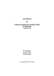
This technical note illustrates how to set up the RS232 control of the Kikusui
PLZ164 or PLZ164WA electronic load in order to use this device in combination
with the Autolab PGSTAT for energy storage devices characterization. The
information provided in this technical note can however be used for other
electronic loads or other devices, using the correct communication protocol.
1|Page
NOVA Technical note 12
2 – Requirements
The following items are required for this technical note:
•
•
•
A Kikusui electronic load 1: the examples shown in this technical note
apply to the following models: PLZ164 and PLZ164WA.
Serial port: the host computer must have a serial port (COM port)
available 2.
Null modem cable 3: a so called null modem cable is required for the
control of the Kikusui electronic load.
Warning
This technical note assumes that the reader is familiar with the Kikusui PLZ164
or PLZ164WA electronic load. If this is not the case, the reader is invited to
consult the user manual of the Kikusui electronic load. Other devices can be
controlled through a similar protocol. Refer to the user manual of the external
device for specific information on the communication setup and the commands
involved in the control of the device.
The PLZ164 and the PLZ164WA have the following specifications in terms of
current and voltage ranges:
•
•
Current ranges: 330 mA (LOW), 3.3 A (MED) and 33 A (HIGH).
Voltage ranges: 15 V (LOW) and 150 V (HIGH).
Other devices can be controlled through a similar protocol. Refer to the user manual of the
external device for specific information on the communication setup and the commands involved
in the control of the device.
2
A USB to serial adapter can also be used.
3
This cable can be purchased in a computer store or online (www.farnell.com).
1
2|Page
NOVA Technical Note 12
3 – Hardware setup
Connect the cable to the serial port of the host computer and to the matching
RS232C connector located on the back plane of the Kikusui electronic load (see
Figure 2).
Figure 2 – Connect the null modem cable to the RS232C connector on the back plane of the
Kikusui electronic load
Switch the electronic load ON and open the Menu by pressing the SHIFT and the
MENU key at the same time on the front panel of the load (see Figure 3).
Figure 3 – Press the SHIFT key and the MENU key on the front panel of the load to open the
configuration menu
3|Page
NOVA Technical note 12
Using the Arrow keys on the front panel of the load, navigate to the Configuration
sub-menu. Press the ENTER key on the front panel to open the sub-menu. In the
configuration sub-menu, open the Interface menu (see Figure 4).
Figure 4 – Open the Configuration – Interface menu by using the Arrow and the ENTER keys
on the front panel of the load
In the interface menu, rotate the rotary knob on the front panel of the load to set
the Control parameter to RS232C. Set the other parameters to the following
values:
•
•
•
•
Baudrate: 19200bps
Data,Stop: 8,2 (only the number of stop bits can be defined, the data
format is fixed to 8 bits)
Parity: NONE (this parameter is fixed)
Ack: OFF
Press the SHIFT and the MENU keys on the front panel to close the Menu.
Warning
Switch off the load and switch it on again in order to validate the new settings.
4|Page
NOVA Technical Note 12
4 – NOVA setup
In the procedure setup, the commands required to control the electronic load can
now be added to the procedure. Before the instrument can be controlled, the
communication must be initialized.
Locate the External device initialize command in the External devices group of
commands and add it to the procedure editor (see Figure 5).
Figure 5 – Adding the External device initialize to the procedure editor
Set the Device name parameter to Kikusui electronic load for example, and click
the
button next to the Settings parameter in the procedure editor to open the
configuration table for this command (see Figure 6).
Figure 6 – Opening the settings table for the External device initialize command
A new window will be displayed (see Figure 7). In this interface, the settings of the
RS232 communication for the external device can be defined.
Figure 7 – The settings of the connection can be defined in the dedicated window
5|Page
NOVA Technical note 12
In this example, set the parameters to the following values (the parameters should
match the settings defined on the load in the previous section):
•
•
•
•
•
•
•
BaudRate: 19200
DataBits: 8
Handshake: None
NewLine: \n
Parity: None
PortName: COM1 4
StopBits: Two
Click the OK button to validate the settings.
Note
Make sure that the External device close command is used at the end of the
procedure before starting the procedure. Each initialized connection must be
closed using the corresponding External device close command (see Figure 8).
Figure 8 – Always close the connection to the external device at the end of the procedure
using the External device close command
5 – Sending instructions to the electronic load
The External device send command can be used to send an instruction to the
external electronic load. To use this command, it must be added to the procedure
editor (see Figure 9).
The actual port name depends on the host computer configuration. Check the port number in the
device manager of the computer (Control panel – System – Device Manager).
4
6|Page
NOVA Technical Note 12
Figure 9 – Adding the External device send command to the procedure
Note
Make sure that the Device name in the External device send command is the
same as in the External device initialize command. The Device name parameter
can be linked, as shown in Figure 9.
A number of control instructions can be sent to the electronic load. For a
complete overview of these commands, please refer to the electronic load user
manualError! Bookmark not defined..
In this technical note, a few examples will be used.
5.1 – Mode of operation
Two modes of operation are commonly used in combination with the Autolab
PGSTAT – Constant Voltage (CV) and Constant Current (CC). The mode of
operation of the electronic load can be set by sending the following commands
through the External device send command:
•
•
Constant Voltage mode: FUNC CV
Constant Current mode: FUNC CC
Note
Command syntax is case sensitive.
For example, setting up the External device send command as shown in Figure 10
will force the electronic load to switch to constant current mode.
7|Page
NOVA Technical note 12
Figure 10 – Setting the load to Constant Current (CC) mode
5.2 – Current range
Three current ranges are available on the Kikusui electronic load. The active
current range can be set by sending the following commands through the External
device send command:
•
•
•
Low current range (330 mA): CURR:RANG LOW
Medium current range (3.3 A): CURR:RANG MED
High current range (33 A): CURR:RANG HIGH
For example, setting up the External device send command as shown in Figure 11
activates the high current range on the electronic load.
Figure 11 – Setting the load to High current range
5.3 – Voltage range
Two voltage ranges are available on the Kikusui electronic load. The active voltage
range can be set by sending the following commands through the External device
send command:
•
•
Low voltage range (15 V): VOLT:RANG LOW
High voltage range (150 V): VOLT:RANG HIGH
For example, setting up the External device send command as shown in Figure 12
activates the high voltage range on the electronic load.
8|Page
NOVA Technical Note 12
Figure 12 – Setting the load to High voltage range
5.4 – Load switch
The electronic load can be switched on or off remotely by sending the following
commands through the External device send command:
•
•
Load On: INP ON
Load Off: INP OFF
For example, setting up the External device send command as shown in Figure 13
switches the electronic load ON.
Figure 13 – Switching the electronic load ON
6 – Receiving instructions from the electronic load
The External device receive command can be used to receive an instruction back
from the external electronic load. The reply from the load is triggered by a query
sent by the External device send command. For this reason, the External device
receive command must be located after an External device send command in the
procedure editor, as shown in Figure 14.
In this example, the External device send command sends the instruction *IDN? to
the electronic load. This instruction is used to request the load to send back the
instrument identification. The response of the load is received by Nova through
the External device receive command and the string returned by the load is stored
in the parameter {0}.
9|Page
NOVA Technical note 12
Figure 14 – Example of a External device receive command following a query sent to the load
using the External device send command
In order to display the response of the electronic load to the user, it is possible to
add a Message box command in the procedure as shown in Figure 15.
Figure 15 – Displaying the answer to the query in a message box
When this procedure is executed, the instrument identification number will be
displayed in the message box (see Figure 16).
10 | P a g e
NOVA Technical Note 12
Figure 16 – The Instrument ID obtained from the instrument through the External device
receive command is displayed in the message box
A number of query instructions can be sent to the electronic load through the
External device receive command. For a complete overview of these commands,
please refer to the electronic load user manualError! Bookmark not defined..
In this technical note, a few examples will be used.
6.1 – Mode of operation?
It is possible to verify the mode of operation of the electronic load by using the
following query in the External device send command:
•
FUNC?
The reply from the instrument can be obtained from the External device receive
command (see Figure 17). The response will be:
•
•
CV: when the instrument is in Constant Voltage mode.
CC: when the instrument is in Constant Current mode.
11 | P a g e
NOVA Technical note 12
Figure 17 – Using the FUNC? query
Note
The Message box command can be used to display the operation mode of the
load.
6.2 – Current range?
It is possible to identify the active current range of the electronic load by using the
following query in the External device send command:
•
CURR:RANG?
The reply from the instrument can be obtained from the External device receive
command (see Figure 18). The response will be:
•
•
•
HIGH: when the high current range is active (33 A).
MED: when the medium current range is active (3.3 A).
LOW: when the low current range is active (330 mA).
12 | P a g e
NOVA Technical Note 12
Figure 18 – Using the CURR:RANG? query
Note
The Message box command can be used to display the active current range of
the load.
13 | P a g e
NOVA Technical note 12
6.3 – Voltage range?
It is possible to identify the active voltage range of the electronic load by using the
following query in the External device send command:
•
VOLT:RANG?
The reply from the instrument can be obtained from the External device receive
command (see Figure 19). The response will be:
•
•
HIGH: when the high voltage range is active (150 V).
LOW: when the low voltage range is active (15 V).
Figure 19 – Using the VOLT:RANG? query
Note
The Message box command can be used to display the active voltage range of
the load.
14 | P a g e
NOVA Technical Note 12
6.4 – Load switch?
It is possible to identify the status of the load switch of the electronic load by
using the following query in the External device send command:
•
INP?
The reply from the instrument can be obtained from the External device receive
command (see Figure 20). The response will be:
•
•
1: when the load is ON.
0: when the load is OFF.
Figure 20 – Using the INP? Query
Note
The Message box command can be used to display the load switch status of
the electronic load.
7 – Conclusion
Using the commands located in the External devices group, it is possible to setup
remote control of commonly used external devices like electronic loads,
programmable power supplies, water bath thermostats, etc. The RS232
communication protocol is straightforward to setup and provides a convenient
way to set specific instrument parameters during a Nova measurement.
Do not forget that it is possible to save new commands in the My Commands
group.
15 | P a g e