1
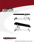
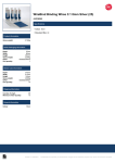
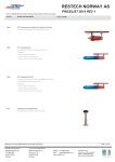
Electrical multiline pilewind winches
WIN 250-3/4/5/6
WIN 500-3/4/5/6
WIN 1000-3/4/5/6
USER MANUAL
SIA „WINWOOD”
Legal address: „Rasas”, Kurna, Kubuļu District, Balvu Region, Latvia, LV-4566
Actual address: Vidzemes Str. 2b, Balvi, Latvia, LV-4501
Tel.: +371 29440812, Fax: +371 4507040
E-mail: [email protected],
http://www.winwood.lv
ENGLISH
Please read this manual before installing and using WINWOOD pilewind winches
WIN250/500/1000 to ensure that the equipment is being used according to safety
requirements and manufacturer’s instructions.
For additional technical features, installation and service instructions and other information
contact WINWOOD Ltd. at www.winwood.lv.
This manual is valid for all types of WINWOOD cable winches WIN250/500/1000. Do not
apply this manual for devices of any other manufacturers!
Winch WIN 250/500/1000 is intended for lifting/ lowering/ stage bars or trusses; hanging
and static suspension of loads above head.
The equipment should not be used for moving loads – lifting or lowering if any person is
under the load.
WIN 250/500/1000 is intended only as a part of stage bar lifting system. The safety of whole
lifting system, safety of its usage load and other characteristics depend on the system
compilation. In case of delivering this particular product, WINWOOD shall not bear
responsibility for the operation of the whole lifting system.
The equipment complies with essential safety and harmlessness requirements.
The equipment is intended for use in the following environmental conditions:
- Ambient temperature – 15 Co to +40 Co;
- Air humidity - not more than 50% in +40 Co or 90% in +20Co;
- Altitude above sea level - not higher than 1000m
The equipment has the following technical and electrical parameters:
- Applicable electrical voltage 400V / 50 Hz / 3F
- Power of electric motor: 1.1 kW – WIN 250; 2,2 kW – WIN 500; 1,5 kW – WIN 1000;
- Selfweight of winch Kg: WIN 250-3 /145kg; WIN 250-4 /152kg; WIN 250-5 /159 kg,
WIN 250-6 /166kg;
WIN 500-3 /170kg; WIN 500-4 /177kg; WIN 500-5 /184kg, WIN 5006 /191kg;
WIN 1000-3 /197kg; WIN 1000-4 /204kg; WIN 1000-5 /213kg, WIN
1000-6 /220kg;
- Safe working load: 250 Kg – WIN 250; 500 Kg – WIN 500; 1000 Kg – WIN 1000;
- Applicable cable - 6mm
- Traveling speed – WIN-250, WIN-500 from 150mm/s to 290 mm/s; WIN-1000 from
40mm/s to 70mm/s (with 6mm cable);
- Traveling distance – up to 12 000mm (with 6mm cable);
- Number of spooling tracks is 3 to 6. The last number of the model name indicates
the number of tracks (for example, WIN 250-N, where N – number of tracks).
2
ENGLISH
General safety information
Upon delivery ensure that the information indicated on the packaging complies
with the required one. Ensure that the equipment has not been damaged during
transportation. If any damages discovered, immediately inform the carrier.
Installation, operation, maintenance and repair are to be performed by properly
qualified personnel only. Proper tools should be used. Ensure that the equipment
is not under voltage; there is no voltage on clamps; the operations performed shall
not cause any dangerous movement or falling of load.
Avoid touching body of electromotor while winch working or right after it has
been stopped, because the temperature of motor cover may reach up to +50Co
during normal operation.
The equipment contains parts which are in motion or under voltage during
operation. Removing protective cover or electrical control unit cover, as well as
inappropriate or incorrect maintenance may cause serious harm to personnel or
other equipment.
3
ENGLISH
Operational restrictions
The equipment is designed for lifting/ lowering loads. Do not use the equipment
for any other purposes! Do not lift/ lower humans with this winch!
Do not load the equipment more than it is allowed by Safe Working Load indicated
on the equipment!
Do not use several winches for lifting one load!
Do not use damaged or malfunctioning equipment!
Do not modify the equipment in any way!
Do not divert attention from the winch during operating the system! Do not use
the winch if it is impossible to fully observe movement of load!
Do not use the winch if there are men under the load!
Do not swing or jerk the load while lifting/ lowering!
Assembling
Installing of winch
When choosing placement of winch, provide at least 700mm wide and 2000mm
high ails for maintenance! This area should be clearly marked with “Maintenance
area – for unauthorised personnel access restricted”
Install winch in the position as indicated in this manual (Picture 1)! If it is necessary
to install the winch in any other way, contact the manufacturer!
4
ENGLISH
5
ENGLISH
Picture 1. Diagram of stage bar lifting system. Examples of placing the winches
(1 – winch)
Upon installing the winch in the intended place, consider the selfweight of
equipment and intended load, including emergency situation! Use appropriate
mounting elements!
Install the hoists only on plane surface of the foundation and mount with four (4)
M12/M16 bolts of respective hardness, washers, and screw nuts with locking
device. Ensure that the foundation is adequately strong to withstand the load. It is
recommended to use steel plate and/or appropriately located steel beam. The
foundation should be designed by qualified personnel.
Picture 2. Winch mounting holes in WIN-250-4.
6
ENGLISH
If it is necessary to set the system in any other way than described in this manual,
it is advisable to contact the manufacturer!
Installing lifting cables
Upon planning the placement of pulley system of lifting cables ensure that the
cables are precisely perpendicular to the rotation axis of the spool and do not rub
against the dividing or closing disks!
Upon installing the stage bar lifting system use only 6mm cable. Use only cable
intended for lifting loads. It is recommended to use a cable by one manufacturer
and of one series in all spooling lines to avoid alterations in the diameter of cable.
Unscrew the central screw nut and mounting bolts and take off the disks to install
the cable to the spool.
If more than 4 cable lines are to be installed, pull 2 or more cables through the
closing disk, which is the nearest to the gear box and dividing disks. Affix them
with the cable clamp plates. The remaining cables pull through the dividing disks
in the same way and affix to the closing disk which is the furthest from the gear
box.
Upon installing cable spools insert the cables in the intended spooling grooves.
Screw the spool with bolts, ensure the central castellated nut against loosening
with locking pin.
Upon affixing the ends of cables with a clamp plates, leave 50mm of cable free.
Ensure fixing the ends of cables against loosening. Affix the cables properly,
because improperly fixed cables may cause falling of load.
The length of lifting cable and installing of limiting switches should be chosen so
that there always were two wraps of cable left on the spool.
Installing limit switch
Limit switch should be initially set when assembling the equipment and every time
when system is being changed or rebuild. Limit switches should be installed or
adjusted by qualified personnel only.
The equipment has two independent limit switches – “travel” and “absolute”. In
normal operational conditions the “travel” switch is used. The “absolute” switch is
intended for back up in case if an error occurs and “travel” switch does not work.
Firstly install the “absolute” switch. The limit switch should be set in the way to
limit the maximally possible load movement, taking into account the time
necessary for fully loaded system to stop. In this case the “absolute” switch should
be installed so that it would not cause any breakage in case of emergency stop of
the system. The “travel” switch should be installed to ensure normal operation of
7
ENGLISH
the system within the space limited by “absolute” switch.
In order to regulate the limit switches, take off body covers of the switches
(yellow) by unscrewing the screws. Each limit switch has two switches – Up and
Down. “Up” switch stops the lifting; “Down” switch stops the lowering of load. Use
bolts (white) to regulate off position of switches.
Connect electric and control cables according to the diagram.
Picture 3. Electric connection diagram.
Maintenance
Regularly, prior to each operation session check the functioning of Emergency
STOP button.
Regularly, but not less than twice per year:
- Check screw mounting, lifting cables and electric connections to prevent
loosening;
- Check condition of lifting cables – there should be no rust, rupture,
damage, breakage, deformation or any other damage. If there are any
damages discovered, replace the damaged part;
- Check tightening of cables to be equal. Regulate the tightening if
necessary;
- Check if the equipment operates without excess non-typical noise or
vibration. Repair the equipment if necessary;
- Check for any oil spillage from the gear box. Contact the manufacturer if
necessary;
- Check tightening of driving gear belt of the limit switch. Regulate it if
necessary;
- Check operation of limit switch. Adjust it if necessary;
- Check motor brakes. Regulate them if necessary.
8
ENGLISH
-
Check if identification marking is visible and well-fixed.
Results of inspections, information about repairs performed should be
recorded in the maintenance register.
Note
This manual may be amended without prior notice. 31.08.2011.
9