1
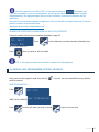
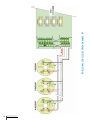
Toxic, explosive and oxygen gas detection control panel
User and Installation manual
Certificado nº FS82426
© 2014 DURAN ELECTRONICA S.L. - All rights reserved · www.duranelectronica.com
I-manDURGAS-v02
RANGE OF COMPATIBLE PRODUCTS
Remote relays module.
DURGAS mini control panel 1 MODULE LINE.
DURGAS Module line display unit.
DURGAS Module line.
Power Supply Control Module.
DURPARK RS485 NO2 detector.
SPARES:
DURGAS Module line.
DURGAS Module line display unit.
5A power supply for DURGAS control panel.
2.4A power supply for DURGAS mini control panel.
Power Supply Control Module.
Remote relays Module.
DURPARK RS485 CO detector.
INDEX
1.INTRODUCTION
pag.
4
2.
PREVIOUS CONSIDERATIONS. . . . . . . . . . . . . . . . . . . . . . . . . . . . . . . . . . . . . . . . . . . . . . . . . . . . . . . 5
3.
OPTICAL INDICATORS . . . . . . . . . . . . . . . . . . . . . . . . . . . . . . . . . . . . . . . . . . . . . . . . . . . . . . . . . . . . 7
4.
INSTALLATION and CONFIGURATION OF OPTIONAL 8 INPUT 4-20mA MODULES .. . . . . . . . . . . . 8
5.
INSTALLATION and CONFIGURATION OF OPTIONAL 4 RELAY MODULES.. . . . . . . . . . . . . . . . . . . . 8
6.
RANGES (f.s.), ALARM and VENTILATION LEVELS AVAILABLE FOR THE VARIOUS GASES. . . . . . . . . 9
7.
PROGRAMMING THE DETECTOR NUMBER USING SW1 (addressing). . . . . . . . . . . . . . . . . . . . . . . 10
8.
RELAY ACTIVATION DEPENDING ON STANDARDS AND GROUPS PROGRAMMED. . . . . . . . . . . . . . 11
9.
MODULE LINE BEHAVIOUR IN CASE OF POWER SUPPLY CUT. . . . . . . . . . . . . . . . . . . . . . . . . . . . . 11
10.
EQUIPMENT OPERATION PROTOCOLS, EMERGENCY MODES. . . . . . . . . . . . . . . . . . . . . . . . . . . . . . 11
11.
FACTORY DEFAULT CONFIGURATION FOR THE DETECTION OF CARBON MONOXIDE (CO)
FOR SPANISH, PORTUGUESE and GERMAN/SWISS STANDARDS. . . . . . . . . . . . . . . . . . . . . . . . . . . 12
12.
DISPLAY INFORMATION WITH A DISCONNECTED MODULE LINE, OFF . . . . . . . . . . . . . . . . . . . . . . 12
13.
KEYPAD FUNCTIONS WITH A DISCONNECTED MODULE LINE, OFF. . . . . . . . . . . . . . . . . . . . . . . . . 13
14.
SYSTEM PROGRAMMING (ENGINEER MODE, MODULE LINE OFF). . . . . . . . . . . . . . . . . . . . . . . . . . 13
15.
PROGRAMMING ASSOCIATING RELAY MODULE . . . . . . . . . . . . . . . . . . . . . . . . . . . . . . . . . . . . . . . 15
16.
DETECTOR TEST . . . . . . . . . . . . . . . . . . . . . . . . . . . . . . . . . . . . . . . . . . . . . . . . . . . . . . . . . . . . . . . . . 15
17.
SENSOR TEST, ONLY COMPATIBLE WITH DURPARK RS485 DETECTORS. . . . . . . . . . . . . . . . . . . . . 15
18.
MODULE LINE START UP. . . . . . . . . . . . . . . . . . . . . . . . . . . . . . . . . . . . . . . . . . . . . . . . . . . . . . . . . . 16
19.
DISPLAY INFORMATION WITH A CONNECTED MODULE LINE. . . . . . . . . . . . . . . . . . . . . . . . . . . . . 18
20.
LED CODES IN THE DETECTORS (Eurosondelco and Siemens CC62P). . . . . . . . . . . . . . . . . . . . . . . 18
21.
LED CODES IN DURPARK RS485 DETECTORS. . . . . . . . . . . . . . . . . . . . . . . . . . . . . . . . . . . . . . . . . . 19
22.
KEYPAD FUNCTIONS WITH THE MODULE LINE CONNECTED. . . . . . . . . . . . . . . . . . . . . . . . . . . . . . 19
23.
INHIBIT DETECTORS FUNCTION. . . . . . . . . . . . . . . . . . . . . . . . . . . . . . . . . . . . . . . . . . . . . . . . . . . . . 20
24.
SENSOR CHANGE (Eurosondelco and Siemens CC62P). . . . . . . . . . . . . . . . . . . . . . . . . . . . . . . . . . 21
25.
DETECTOR CALIBRATION (Eurosondelco and Siemens CC62P). . . . . . . . . . . . . . . . . . . . . . . . . . . . 21
26.
ZERO ADJUSTMENT (2 modes). . . . . . . . . . . . . . . . . . . . . . . . . . . . . . . . . . . . . . . . . . . . . . . . . . . . . 22
27.
CALIBRATION TABLES (See data for EXP detectors in their manuals) . . . . . . . . . . . . . . . . . . . . . . 22
28.
CALIBRATION DATA, SONDELTOX DETECTORS 4-20mA. . . . . . . . . . . . . . . . . . . . . . . . . . . . . . . . . . 23
29.
POSITIONING OF THE ADJUSTMENT POTENTIOMETERS. . . . . . . . . . . . . . . . . . . . . . . . . . . . . . . . . . 24
30.
MEASURING POINTS and adjustment potentiometers, CO, NO2 and O2 Eurodetectors. . . . . . . . . 24
31.
ENTERING CALIBRATION MODE (PUTTING MODULE LINE IN OFF) . . . . . . . . . . . . . . . . . . . . . . . . . 25
32.
CALIBRATION PROCEDURE FOR CO AND NO2 DURPARK RS485 DETECTORS. . . . . . . . . . . . . . . . . 25
33.
MODULE LINE PROGRAMMING OPTIONS, ON MODE. . . . . . . . . . . . . . . . . . . . . . . . . . . . . . . . . . . . 27
34.
MODULE LINE TECHNICAL CHARACTERISTICS. . . . . . . . . . . . . . . . . . . . . . . . . . . . . . . . . . . . . . . . . 31
35.
TECHNICAL CHARACTERISTICS Eurosondelco and Siemens CC62P CO/NO2, RS485-IP65 detectors . . . . 32
36.
TECHNICAL CHARACTERISTICS CO and NO2 DURPARK RS485-IP20 DETECTOR. . . . . . . . . . . . . . . 32
37.
EURODETECTORS GENERAL CONNECTIONS. . . . . . . . . . . . . . . . . . . . . . . . . . . . . . . . . . . . . . . . . . . 33
38.
DURPARK RS485 DETECTORS CONNECTIONS. . . . . . . . . . . . . . . . . . . . . . . . . . . . . . . . . . . . . . . . . . 34
39.
CONNECTING 8 DETECTORS + ONE 4-20mA MODULE . . . . . . . . . . . . . . . . . . . . . . . . . . . . . . . . . . 35
40.
CONNECTING 8 DETECTORS + ONE 4-20mA MODULE + ONE RELAY MODULE. . . . . . . . . . . . . . . 36
41.
CONNECTING TWO 4-20mA MODULES . . . . . . . . . . . . . . . . . . . . . . . . . . . . . . . . . . . . . . . . . . . . . . 37
42.
AUXILIARY POWER SOURCES INSTALLATION. . . . . . . . . . . . . . . . . . . . . . . . . . . . . . . . . . . . . . . . . . 38
43.WARRANTY . . . . . . . . . . . . . . . . . . . . . . . . . . . . . . . . . . . . . . . . . . . . . . . . . . . . . . . . . . . . . . . . . . . . 39
I-manDURGAS-v01
3
1. INTRODUCTION.
The new DURGAS control panels have been designed for the simultaneous detection of up to four
different gases per module line, widening the field of application for Industry in general, Car Parks and
Tunnels.
Equipped with “Plug and Play” technology, it automatically detects the quantity and type of detectors,
as well as various devices connected to its loop, and auto configures the ranges, ventilation levels and
alarm levels appropriate to each case and gas type, adjusting them to the various current TLVs and
standards.
Detectors of any gas and working principle can be connected to each module line loop, in addition to
relay modules and 4-20mA to RS485 conversion interfaces.
The system is backward compatible, being able to control the whole detector range of the previous
models EUROSONDELCO, SIEMENS CC62P, DURTEX, DURTOX, DIREX manufactured up until now, as
well as the new models DURPARK RS485.
Three standards can be programmed; Spanish, Portuguese or German/Swiss, this last one with two
different programmable working modes, standard or averages. Four languages can also be programmed;
Spanish, English, Portuguese or German.
It allows programming up to 4 single ventilation groups, or 3 double speed ventilation groups,
therefore allowing individual maneuvers in the case of different gases, or sectoring maneuvers for
the same gas. For cases in which 3 gases are used in the same module line, it is possible to program 4
groups and use only three groups.
The control panel is expandable from one to four module lines, with a capacity of up to 16 detectors
per module line (64 in total), being able to control detectors for CO, H2S, SO2, HCN, NO, NO2, NH3, HCL,
CL2, CO2,H2, O2 and explosive gases, each one with its different ranges and alarm levels, whatever their
communications system, RS485 up to maximum distance of 1Km, or the standard 4-20mA, this last one
through the use of an optional interface that converts this signal to RS485 and automatically addresses
them, being it possible to connect in one module detectors with both communication systems.
Each module line incorporates four voltage free, switched relay outputs, one switched alarm tension
output at 12V, one auxiliary tension output of 12V for device power supply, plus one for loop power
supply, all fuse protected, the alarm output, the auxiliary one and the loop one, with automatic rearm
fuses.
The maneuver capacity of the module lines is expandable by using remote relay modules that include
four maneuver relays plus a general alarm one, all of them with switched outputs, dry contact and
fuse protected. They can be connected at any point in the loop up to a maximum of five modules per
module line, and allow programming of any type of association between module line relays, remote
relay modules and the detectors, being possible to program, for example, the association of one relay
for each detector.
Each module line works independently, incorporates a backlit, 16x2 character line LCD display, plus
seven optical indications, internal acoustics and a six key keypad.
The control panel includes a 13,8V 5A power supply source, with a module that controls battery charge,
presence and status, and date, time and data traffic between module lines, plus a general fault output.
Optionally an RS485 communications module can be added, which allows integrating the system in
MODBUS or OPC-SERVER format.
A mini DURGAS version is also available, not expandable and with a single module line with the
same characteristics, without the possibility of integration and with a 2,4A power supply.
4
© 2014 DURAN ELECTRONICA S.L.
All rights reserved · www.duranelectronica.com
2. PREVIOUS CONSIDERATIONS.
For grid power supply (230 VAC) to the panel, it is recommended to have an independent outlet
protected with a 10A bipolar magneto thermal switch.
For the correct operation of the various anti-parasitic systems included in the equipment it is
necessary to have a good ground connection.
Carry out cabling for the relay outputs through different cable ducts to those of the detection
loops.
For the activation of motors, you must use contactors controlled by the module line relay outputs,
or the optional relay modules, never the relay contacts directly.
To prevent interferences do not install the equipment or detectors close to electrical panels, motors
or variable-frequency drives.
Do not drill holes in the cabinet, use the precut holes provided
Do not handle or dismantle any module line, detector or mechanism when the equipment is
powered.
In case of any fuse being broken, always use the fuse value indicated in the documentation or in
the printed circuit board. Not following these indications could result in damage to the equipment.
The “automatic reset” protection fuses open when they detect a short circuit or consumption
increase. If this should happen, disconnect the cables from the control panel terminals, check the
cabling, check that the consumption of the elements which it is powering does not exceed the
capacity indicated in this manual and wait for some time until the fuse resets.
We recommend carrying out the installation with shielded cable 4-wire 2x1.5mm for power supply
and 2x0.25mm, twisted pair, for A-B communications. The maximum distance between the control
panel and the last detector or device connected to the loop must not exceed 1 Km. Connect the
earth drain mesh or cable, only in the control panel, using the accessory supplied.
Ensure that the connections between the module lines and the detectors are correct. This is done in
parallel and any kind of branching is allowed, as long as the position of the negative and positive
supply terminals and the A and B communications terminals are respected. No resistor is needed at
the end of the line.
Please consider that for longer cabling distances, >400/500m, and due to the drop in voltage in the
cable, it may be necessary to install supplementary power supplies, connected throughout the loop,
that guarantee the correct supply to the detectors. Increasing the cable section from 1.5 to 2 or
even 2.5mm may also help.
I-manDURGAS-v01
5
Before connecting the detectors to the module line loops, make sure that these are disconnected.
The gas detector heads in type IP65 toxic gas detectors must be covered at the moment of
connection, until the system has stabilized, around 40/60 min.
If the control panel is used to control ATEX detectors protecting classified areas, it must be installed
outside the classified area.
Connect the battery respecting the polarity. Red for positive and black for negative. Only a 12V
7.5Ah battery can be connected.
Although the equipment can work without a battery, we recommend that it is used. If at the
moment of module line connection there is no battery present, the module line will configure itself
to not check battery state. If one is used later on, the equipment will recognize it within 20 s after
it is connected.
The optimal installation height for CO detectors is 1,8-2m from floor, and its coverage is 200m2
(according to current standards).
Do not mix in one same loop DURPARK RS485 detectors and EUROSONDELCO, or SIEMENS CC62P
detectors.
Do not drill holes into the detectors. Use those provided for fastening and use the cable glands
included in the IP65 detectors for cable entry, and always hose type.
Do not install the detectors or control panels near a heat source.
Do not paint the detectors. If you need to paint the area, remove the detectors and, if you installed
DURPARK RS485 model detectors, cover the base.
Do not, in any case, exceed the technical specifications described in the manual without first
consulting our technical service.
Install the control panel and detectors when all work has been completed in the installation.
6
© 2014 DURAN ELECTRONICA S.L.
All rights reserved · www.duranelectronica.com
3. OPTICAL INDICATORS.
All optical indicators have their corresponding identification message on the display.
1- General fault optical indicator. It will illuminate for any kind of malfunction.
2- Inhibited acoustics optical indicator, which illuminates to indicate that silent operation has been
chosen, or was inhibited when some type of event was activated. With a permanent character, its
rearming will happen automatically, only if new fault events appear.
3- Optical indicator for earth fault, it illuminates when some point of the module line cabling is
earthed. This indication will illuminate in all module lines simultaneously, even if the earthing happens
only in one.
4- Optical indicator of battery fault, it illuminates to indicate that the battery is low in tension, <9V, or
in a bad state, or absent after having been included.
5- Optical indicator of grid presence, it illuminates when there is a fault in electrical supply from the
power grid 230V AC.
6- Optical indicator of unblocked keypad, it illuminates after typing in the correct password,
throughout the time that the keypad remains active, 20s.
7- Optical indication of rearming or manual acknowledging of alarms, only if explosive gas detection
(EXP) is programmed in the module line.
I-manDURGAS-v01
7
4. INSTALLATION AND CONFIGURATION OF OPTIONAL 8 INPUT 4-20mA MODULES.
The detectors connected to the interfaces are automatically numbered, following the number of the
input to which they are connected.
• If you select JP1 in ON for the first interface, the connected detectors will be numbered from 1 to 8,
and will belong to group 1, in the current interfaces SW1-3 in ON, if you decide to connect just this
interface and RS485 format detectors in the same loop, the first RS485 detector must be numbered as
number 9.
• If you select JP1 in OFF for the second interface, the connected detectors will be numbered from 9
to 16, and will belong to group 2, in the current interfaces SW1-3 in OFF, if you decide to connect
just this interface and RS485 format detectors in the same loop, the first RS485 detector must be
numbered as number 1.
You may also opt for installing one or two 4-20mA in the same loop, without any RS485 format
detector.
5. INSTALLATION AND CONFIGURATION OF OPTIONAL 4 RELAY MODULES.
Up to five of these modules may be connected per module line, with two possible configurations:
1st MIRROR MODE: select P1 ON (jumper on), when a relay in the module line activates, of the four
available belonging to a group, the associated relay will activate in the module, as it is programmed in
the module line.
In this mode the SW1 switch position in the module is ignored
Operation in mirror mode (associated to a module line)
In the MODULE
LINE
RL1- On
RL2- On
RL3- On
RL4- On
RL5- ALARM
In the REMOTE
RELAYS MODULE
RL1- On
RL2- On
RL3- On
RL4- On
RL5- On
2nd RELAY MODULE ASSOCIATED TO DETECTORS: select P1 OFF (jumper removed), the relay will
activate when its associated detector reaches ventilation level 1, as programmed in the module line.
In this last case, the general alarm relay will not activate.
SWITCH SW1 CONFIGURATION.
1
ON
Module
Relay 1
8
2 RELAY
ON RL1
RL2
RL3
RL4
RL5
© 2014 DURAN ELECTRONICA S.L.
All rights reserved · www.duranelectronica.com
DETECTOR
1
2
3
4
ALARM
1
OFF
Module
Relay 2
2 RELAY DETECTOR
ON RL1
5
RL2
6
RL3
7
RL4
8
RL5
ALARM
1
ON
Module
Relay 3
2 RELAY
OFF RL1
RL2
RL3
RL4
RL5
DETECTOR
9
10
11
12
ALARM
1
OFF
Module
Relay 4
RELAY DETECTOR
2
OFF RL1
13
RL2
14
RL3
15
RL4
16
RL5
ALARM
You may for example: install 4 modules associated to detectors and a 5th in mirror mode (associated to
a module line) to remotely duplicate the maneuvers carried out in the module line.
In this last case, the module line reading mode must be programmed in sequential mode, and the
module SW1 switch configuration will be taken into account.
6. RANGES (f.s.), ALARM and VENTILATION LEVELS AVAILABLE FOR THE VARIOUS GASES.
Gas type
Ranges (f.s.)
Programming
increase
Minimum
programmable
level
Maximum
programmable
level
Factory default levels for Vent1 – Vent2,
Alarm Level
Carbon
Monoxide CO
0-300 ppm
10 ppm
10 ppm
290 ppm
50-75-100 ppm
Oxygen O2
0-25 %
1%
1%
24%
18-15-24%
Carbon
Dioxide CO2
0-5.000 ppm
0-10.000 ppm
0-20.000 ppm
100 ppm
100 ppm
500 ppm
100 ppm
100 ppm
500 ppm
4.500 ppm
9.000 ppm
19.000 ppm
1.500-2.000-3.000 ppm
3.000-4.000-6.000 ppm
4.000-8.000-12.000 ppm
Nitrogen
Dioxide NO2
0-20 ppm
0-50 ppm
0-100 ppm
0.5 ppm
1 ppm
1 ppm
0.5 ppm
1 ppm
1 ppm
19 ppm
45 ppm
90 ppm
2-5-10 ppm
15-20-25 ppm
25-40-50 ppm
Sulfur Dioxide
SO2
0-20 ppm
0-50 ppm
0-100 ppm
0.5 ppm
1 ppm
1 ppm
0.5 ppm
1 ppm
1 ppm
19 ppm
45 ppm
90 ppm
0,5-1-2 ppm
2-4-10 ppm
15-20-25 ppm
Chlorine CL2
0-20 ppm
0-50 ppm
0-100 ppm
0.5 ppm
1 ppm
1 ppm
0.5 ppm
1 ppm
1 ppm
19 ppm
45 ppm
90 ppm
0,5-1-2 ppm
2-4-10 ppm
15-20-25 ppm
Nitrogen
Monoxide NO
0-20 ppm
0-50 ppm
0-100 ppm
0.5 ppm
1 ppm
1 ppm
0.5 ppm
1 ppm
1 ppm
19 ppm
45 ppm
90 ppm
5-8-10 ppm
15-20-25 ppm
25-50-75 ppm
Ammonia NH3
0-20 ppm
0-50 ppm
0-100 ppm
0.5 ppm
1 ppm
1 ppm
0.5 ppm
1 ppm
1 ppm
19 ppm
45 ppm
90 ppm
5-8-10 ppm
15-20-25 ppm
25-50-75 ppm
Hydrogen
Sulfide H2S
0-20 ppm
0-50 ppm
0-100 ppm
0.5 ppm
1 ppm
1 ppm
0.5 ppm
1 ppm
1 ppm
19 ppm
45 ppm
90 ppm
5-8-10 ppm
15-20-25 ppm
25-40-50 ppm
Hydrogen
Cyanide HCN
0-20 ppm
0-50 ppm
0-100 ppm
0.5 ppm
1 ppm
1 ppm
0.5 ppm
1 ppm
1 ppm
19 ppm
45 ppm
90 ppm
5-8-10 ppm
15-20-25 ppm
25-40-50 ppm
Hydrogen
Chloride HCL
0-20 ppm
0-50 ppm
0-100 ppm
0.5 ppm
1 ppm
1 ppm
0.5 ppm
1 ppm
1 ppm
19 ppm
45 ppm
90 ppm
5-8-10 ppm
12-20-25 ppm
25-40-50 ppm
Explosive
Gases EXP
0-100%
L.E.L
1%
L.E.L
10%
L.E.L
80%
L.E.L
20%-40% L.I.E
Prealarm/Alarm
I-manDURGAS-v01
9
IMPORTANT: The ranges (f.s.) of the detectors in 4-20mA format connected to the optional
interfaces must be manually programmed in the module line, and cannot exceed the levels shown in
the table above. For all other detectors, the first available range from those shown in the table above
will be automatically selected.
7. PROGRAMMING THE DETECTOR NUMBER USING SW1 (addressing).
Detector nr
01
02
03
04
05
06
07
08
09
10
11
12
13
14
15
16
1
On
Off
On
Off
On
Off
On
Off
On
Off
On
Off
On
Off
On
Off
2
On
On
Off
Off
On
On
Off
Off
On
On
Off
Off
On
On
Off
Off
3
On
On
On
On
Off
Off
Off
Off
On
On
On
On
Off
Off
Off
Off
4
On
On
On
On
On
On
On
On
Off
Off
Off
Off
Off
Off
Off
Off
NUMBERING DETECTORS ACCORDING TO NUMBER OF GROUPS:
1 GROUP
2 GROUPS
4 GROUPS
DETECTORS 1* TO 16
GR1 DETECTORS 1* TO 16
GR2 DETECTORS 9* TO 16
GR2 DTR. 5* GR3 DTR. 9* TO GR4 DTR. 13* TO
GR1 DTR. 1* TO 4
TO 8
12
16
Always start numbering each group with the detector number marked with (*), and remember that the
parameters of each group can be independent, the gas to be detected being the same or different by
group.
The number of groups is related to the number of speeds or maneuver outputs that each standard
requires, so for example the Portuguese standards requires that the maneuver act on double speed
motors, therefore two relays per motor will be needed, so two groups per module line will have to be
programmed.
10
© 2014 DURAN ELECTRONICA S.L.
All rights reserved · www.duranelectronica.com
8. RELAY ACTIVATION DEPENDING ON STANDARDS AND GROUPS PROGRAMMED.
Standard
Spanish
Spanish
Spanish
Portuguese
Portuguese
1 GROUP 2 GROUPS 4 GROUPS
X
X
X
X
X
RELAYS ACTIVATED
1-3
1-3-2-4
1-2-3-4
1-3 1st Speed 2-4 2nd Speed
1-3 1st Speed 2-4 2nd Speed
9. MODULE LINE BEHAVIOUR IN CASE OF POWER SUPPLY CUT.
1.- In case of a power cut happening, if a battery was not installed, the module line will disconnect.
When power is restored, it will automatically connect, with all the parameters that it had programmed
before the power cut.
2.- If a battery was installed, the module lines will dim the display lighting to save energy. When the
battery reaches 10V, a battery fault message will show on the display, along with an acoustic signal. If the
power cut persists, when the battery reaches 9V the module line will automatically disconnect, showing.
Module line reconnection will happen as described in the first case.
10. EQUIPMENT OPERATION PROTOCOLS, EMERGENCY MODES:
In these modes some possible faults in the system hardware are considered. So that the system may
continue operating, at a basic level, two possible operating modes are included, independently of which
failure takes place.
MODULE LINE FAULT.
If, for example, in a control panel composed of four module lines, number 2 stopped working, the first
module line will work normally and 3 and 4 as number 1, if it happens in its first connection, or with
the number it had last time it worked properly. Time and date information and all dependent options
would be 100% operational.
BASE, POWER SUPPLY AND MANAGEMENT MODULE FAULT.
If this module, common to all the module lines, would stop working once the system is operating
normally, two minutes after not receiving any information in the module lines these will go into
emergency mode, and the time base will now be managed in the module line/s.
If, before initializing the system, the power supply and management module is not working, after 20 s,
all module lines present would be numbered as module line 1, or with the last valid number they had,
as the module will not initialize them, and they would go on to work in emergency mode.
In emergency mode, the management of the power supply, battery, grid, cyclic ventilations if
programmed, etc…, will not be operational. In any of these cases, the following message will show up
on the display, to warn about the situation,
alternating with the rest of the information on the display.
I-manDURGAS-v01
11
11. FACTORY DEFAULT CONFIGURATION FOR THE DETECTION OF CARBON MONOXIDE
(CO) FOR SPANISH, PORTUGUESE and GERMAN/SWISS STANDARDS.
Standard
Spanish
Po r t u g u es e(International)
Instantaneous
mode
30 minute
instantaneous
mode
On. Ventilation Off. Ventilation
50 ppm
1st Speed 50
ppm
2nd Speed
100 ppm
1st Speed
100 ppm
1st Speed
90 ppm
2nd Speed
100 ppm
<50 ppm
Entry delay
1 min
1st Speed <50
1 min
ppm
2nd Speed
1 min
<100 ppm
German – Swiss
Exit
delay
Alarm level
Nr. of
Groups
2 min
100 ppm
Instantaneous
1-2-4
2 min
200 ppm
2 min
Instantaneous
On 200 ppm
Off 3 m
1-2-4
delay
80 ppm
1 min
1 min
80 ppm
0 min
0 min
90 ppm
0 min
0 min
On 250 ppm
Instantaneous
2
2
IMPORTANT: In all the menus described in this manual, where the module line carries out a scan
of the loop in search of detector families, depending on the families connected to the loop, the module
line will only show the Durgas-Durpark RS485-Eurosondelco and Siemens CC62P families.
The families of detectors Durtox-Durtex and Direx are included in the DURGAS family.
12. DISPLAY INFORMATION WITH A DISCONNECTED MODULE LINE, OFF:
12
© 2014 DURAN ELECTRONICA S.L.
All rights reserved · www.duranelectronica.com
13. KEYPAD FUNCTIONS WITH A DISCONNECTED MODULE LINE, OFF:
CHANGE OF LANGUAGE
Press,
and Insert Engineer code shows (6666 factory default).
Current language appears, press
and with each touch, ENG, Portuguese or Deutsch will show
up, confirm chosen language by pressing
GENERAL KEYPAD SEQUENCE, IN PROGRAMMING, ENGINEER CODE:
Press,
to go to the next value, or advance between menus.
Press,
to go back to the previous value, or move back between menus
Press,
to select the entry in the menu you require, and memorize parameters.
Press,
to increase a selection.
Press,
to decrease a selection and
to memorize selection.
14. SYSTEM PROGRAMMING (ENGINEER MODE, MODULE LINE OFF)
If you do not need to modify any parameters, go directly to start up, on page (nº página). If not:
Press,
6666 (factory default)
I-manDURGAS-v01
13
Each time
is pressed the following menus will appear, with the following sequence:
To move between the various menus, and program different options, follow the instructions shown on
the display.
1- Select standard, Spanish, Portuguese, German/Swiss standard or averages.
2- Select 1-2 or 4, depending on the programmed standard only 1-2 may be shown.
3- Configure the group, select the number you want to modify, program gas type, the range,
ventilation level by group, (depending on standard and/or programming) alarm level,
ventilation activation delay and deactivation delay.
4- Allows programming the association of remote relays to the desired groups.
5- Select a new 4-figure number for engineer access code.
6- Adjust parameters for clock, time, date and year, it will only be necessary to carry out this
adjustment in a single module line, the rest will synchronize automatically.
7- Use this to return to factory default parameters. You will be asked for the engineer code.
8- Use this to erase all events stored in the memory.
9- Allows individually verifying in real time the status of each detector.
10- Allows carrying out a test of the status of all detector sensors without using gas.
11- Use to calibrate the detectors connected to the loop.
12- Exit programming or continue or stay in current mode.
NOTE: if once inside this mode no key is pushed for 30s, the system will exit automatically
to the initial OFF position. Not applicable to menus 9,10 and 11.
14
© 2014 DURAN ELECTRONICA S.L.
All rights reserved · www.duranelectronica.com
15. PROGRAMMING ASSOCIATING RELAY MODULE:
Inside the engineer menu, advance up to menu 4 and press
Press,
you want and
or
or
it will show:
to move the < symbol to the group
to select an associated group 1-2-3-4, depending on
the number of groups programmed. If the remote modules are configured in mirror mode, the
programming will be common to all the modules installed.
If you do not wish to associate a relay of the remote module to a group, select GTo exit this mode press
repeatedly.
By using this menu, and the remote relays operating modes described in pages 8 and 9, you may make
any combination of associations between relays, groups and detectors, providing the system with great
flexibility.
16. DETECTOR TEST.
Inside the engineer menu, advance up to menu 9 and press
identify the type of detectors installed, and when finished will show:
Press,
the control panel will search and
to go to the next and
to exit this mode.
The measurement in real time of the selected detector will show up.
If it did not communicate with the module line an ERROR message will show up in the display.
17. SENSOR TEST, ONLY COMPATIBLE WITH DURPARK RS485 DETECTORS.
Test designed for sporadic use. Continuous use could damage the sensor.
It allows carrying out a sensor status test of all detectors connected to the module line without using
gas.
I-manDURGAS-v01
15
From the engineer menu, advance up to menu 10 and press
the following screens will show.
When finished, B will appear in the position belonging to the assigned detector number if everything
is correct.
F will appear in the position belonging to the assigned detector number if there is a fail.
A will appear in the position belonging to the assigned detector number if it is not connected “absent”
In the example in the image above, the sensors of detectors of the detectors 1-2-3-4-5-6-7 are
working correctly, number 8 gives a fail signal, numbers 9-10-11 work correctly, number 12 gives a fail,
numbers 13-14 work correctly and 15-16 are not installed (Absent).
The letter K identifies DURPARK RS485 detectors.
The led codes during this test are:
Alternating fast, green and red during verification time.
When the test finishes, to locate the detectors in the installation look for
that the sensor is in correct state.
fixed green, indicating
A salvo of 3 red blinks, with a cadence of 2s, indicated that the sensor is at
the end of its useful life or in bad state. Substitute it as soon as possible for a new one.
If you enter sensor test, and no DURPARK RS485 detector is found, the following message will
show on the display and exit automatically from the menu
18. MODULE LINE START UP:
Press,
shows.
4444 (factory set).
If the code is correct, the following sequence will start in the display.
16
© 2014 DURAN ELECTRONICA S.L.
All rights reserved · www.duranelectronica.com
25s countdown, after which shows up:
Remote relay modules, mirror mode (associated to the module line), or associated to groups, if any are
detected, if not these messages will not show up.
Number and type of detector, gas, type of communication and interface number, 1 or 2, if an interface
is detected, if not these messages will not show up.
A: with interfaces manufactured up to date and B: with new model, DURGAS, interfaces.
Detectors found according to model, represented in the following way:
DURTEX and DURTOX detectors.
Previous models, EUROSONDELCO.
SIEMENS CC62P.
DURPARK RS485 detectors.
Not installed or not found.
IMPORTANT: DURPARK RS485 detectors and EUROSONDELCO, DURGAS or SIEMENS CC62P
cannot be mixed in the same loop.
Quantity of detectors found.
The addressing number assigned to each detector, from 01 to 16 and the type of gas, CO-NO2-EXP etc.
I-manDURGAS-v01
17
Number of groups that have been detected or programmed, and quantity of active groups, from 1 to 4.
or
if it is not connected.
If an error was detected, because the programming does not coincide with what has been installed,
or because of some error in the cabling,
will show. The module line will disconnect and the
fault led will light up. Check programming, loop cabling and try again.
19. DISPLAY INFORMATION WITH A CONNECTED MODULE LINE.
Nve1=Ventilation level 1 / Nve2=Ventilation Level 2 / Nala=Alarm Level and INH= Detector Inhibited.
20. LED CODES IN THE DETECTORS (Eurosondelco and Siemens CC62P).
Rapid blinking:
Initializing, the detector still has not been recognized by the module line at the time of connection.
Another possible cause could be a communication error.
18
© 2014 DURAN ELECTRONICA S.L.
All rights reserved · www.duranelectronica.com
Sequential lightning up while detector is at rest:
Detector functioning correctly.
Fixed lighted up:
Only in CO detectors, indicates that CO concentration detected is at or above 50ppm.
21. LED CODES IN DURPARK RS485 DETECTORS.
Alternate lighting up green red:
Initializing, the detector still has not been recognized by the module line at the time of connection.
Also indicates communication error, if the detector has not communicated with the module line for
more than 2 min, once it has been recognized
Red, fixed lighted up:
In CO detectors, it indicates that the detected concentration is at or above 50ppm. In
NO2 detectors it indicates that the detected concentration is at or above 3ppm. This indication is
independent from the level programmed in the module line.
Red, slow intermittent:
Uncalibrated detector, incorrectly calibrated or detector error.
Green sequential blinking, each time it communicates with module line:
Correct functioning.
22. KEYPAD FUNCTIONS WITH THE MODULE LINE CONNECTED.
Every time the keypad is handled after the symbol of led
4444 (factory default) must be inserted again.
has turned off, the user code
If,
is pressed user programming is entered.
If,
is pressed it changes type of ventilation for each group, first select the group you wish to
I-manDURGAS-v01
19
change (only if there is more than one), up
Once selected confirm with
ventilation
or
followed by
down.
or with
selecting the type of
needed: Automatic activates automatically when the programmed levels are reached, Manual is always
activated, Stop is always off. Confirm change with
If,
is pressed it activates or inhibits the internal acoustics in the module line.
When a common acoustic signal, such as grid fault, battery fault or earth fault, is set off, it will be
enough to inhibit acoustics in a single module line to inhibit the others.
if,
is pressed, it will show the model, software version, date, time and module line number.
If, after this,
is pressed, it will show, each time it is pressed, how the module line is configured.
When explosive gases are programmed (EXP), press
to manually rearm a previous state of
prealarm or alarm, led 7 turned on. Rearming will only happen if at the moment the key is pressed the
level detected by the module line is lower than the programmed level.
If ,
is pressed, the module line will disconnect.
23. INHIBIT DETECTORS FUNCTION.
Allows inhibiting detectors that are causing problems due to breakdown or decalibration.
Enter user menu, advance up to menu 6 and press ,
20
© 2014 DURAN ELECTRONICA S.L.
All rights reserved · www.duranelectronica.com
the display will show
Press,
to choose the detector and
to change its
state, INH or ACT. To exit press.
24. SENSOR CHANGE (Eurosondelco and Siemens CC62P).
When the sensor reaches the end of its useful life, cannot be calibrated, does not respond, or shows
signs of instability, it will be necessary to substitute it. To do so, follow these steps:
1. Disconnect the module line unit to which the detector is connected.
2. Unscrew the 4 screws on the cover of the detector.
3. Disconnect the CN1 connector that connects the sensor and the circuit.
4. Remove the sensor, unscrewing it from its box.
5. Insert the new sensor in the detector.
6. Remove the bridge that there is in the sensor connector.
7. Insert connector in CN1.
8. Proceed to adjust the zero and calibrate with gas as described below.
25. DETECTOR CALIBRATION (Eurosondelco and Siemens CC62P).
All detectors manufactured by DURAN ELECTRÓNICA have been calibrated using pattern gas in our
laboratories and, therefore, do not need to be calibrated during the initial startup of the installation.
Remember that detectors should be checked, at least, once a year.
Before proceeding with calibration, make sure that detectors have been connected at least for 1 hour.
For the ZERO references to stabilize, make sure that the gas sensor heads of all detectors, except O2
detectors, have had their covers on for at least 30 minute. You may also use Nitrogen (N2) to adjust
ZERO.
PATTERN GAS, AND RECOMMENDED CALIBRATION FLOW FOR EACH GAS:
Type of detector
CO
H2S
SO2
NO
NO2
HCL
CL2
HCN
NH3
O2
CO2
EXP
Pattern gas in ppm
150
20
20
20
10
20
5
10
20
O2 at 25% or ambient air
1.000
2.5% Vol. = 50% L.E.L
Gas flow ml/min
150
400
400
400
400
1.000
1.000
1.000
250
250
500
150
I-manDURGAS-v01
21
26. ZERO ADJUSTMENT (2 modes).
Not applicable to other gases, nor to detectors connected to 4-20mA interfaces.
MODE 1: Using the display in the Module line unit.
Verify gas concentration in the display. If it is other than “000” slowly adjust the ZERO potentiometer
up to the moment this value shows up on the display.
MODE 2: Without the display, and with a measuring instrument.
Position the instrument in the scale of 2V DC. Connect the negative to the GND point and the positive
to the TP+ point of the detector. Turn the ZERO potentiometer slowly to the left or right until an
appropriate tension reading is obtained (see calibration tables page 23).
CALIBRATION WITH GAS (2 modes).
Due to the importance and sensitivity of this point, all work must be carried out by qualified
personnel, with the knowledge and tools necessary to guarantee the correct later functioning of the
detector.
MODE 1, Using the module line display and without a measuring instrument.
Take cover off the detector and insert optional adapter.
Apply gas with the concentration and flow indicated in the calibration table, and wait for the reading
to be stable.
Adjust the GAIN or CAL potentiometer in the detector until the concentration equivalent to that of the
pattern gas used is reached (for example in the case of CO=150ppm).
MODE 2, without looking at the module line display and with measuring instrument.
Position the instrument in the 5V DC scale, connect the negative of same to the GND point and the
positive to the TP+ point.
Adjust the GAIN or CAL potentiometer in the detector until a reading in mV appropriate to the gas
concentration being used is obtained, following the calibration tables in page 23.
27. CALIBRATION TABLES (See data for EXP detectors in their manuals).
O2 DETECTORS, RS485
22
Level (%)
Tension (V dc)
0
0
5
0.8
10
1.6
15
2.38
20
3.18
25
4
© 2014 DURAN ELECTRONICA S.L.
All rights reserved · www.duranelectronica.com
CO DETECTORS, RS485
Level (ppm)
Tension (V dc)
0
0.1
50
0.6
100
1.1
150
1.6
200
2.1
250
2.6
300
3.1
350
3.6
NO2 DETECTOR, RS485
Level (ppm)
Tension (V dc)
0
0.1
5
1.1
10
2.1
15
3.1
20
4.1
OTHER GASES, RS485
Level (ppm)
Tension (V dc)
0
0
50
1
100
2
150
3
100
4
28. CALIBRATION DATA, SONDELTOX DETECTORS 4-20mA:
If measuring in mA = 16X (applied gas concentration) ÷ range of detector in ppm +4.
If measuring in mV = (16X (applied gas concentration) ÷ range of detector in ppm +4) X10.
Example: NO2 detector, measuring range 0-20ppm, 10ppm calibration gas used.
In mA, 16X10÷20+4=12mA.- (in this case the zero will be 4 mA).
In mV, (16X10÷20+4) X10=120mV.- (in this case the zero will be 40 mV).
I-manDURGAS-v01
23
29. POSITIONING OF THE ADJUSTMENT POTENTIOMETERS:
Detectors – SONDELTOX 4-20mA.
In the DURTOX and DIREX detectors, the adjustments are carried out by a special software
and hardware, and it is therefore necessary to return them to the factory.
30. MEASURING POINTS and adjustment potentiometers, CO, NO2 and O2 Eurodetectors
Eurodetectors- CO,NO2 detectors
24
© 2014 DURAN ELECTRONICA S.L.
All rights reserved · www.duranelectronica.com
Eurodetectors –detectors –O2
31. ENTERING CALIBRATION MODE (PUT MODULE LINE IN OFF):
Press,
and press
and type in the engineer code, 6666,
move on to the calibration menu (10),
A sequence will commence, searching for the type of detectors installed.
First it will search for DURGAS or DURPARK RS485 series detectors, and then for EUROSONDELCO and
SIEMENS CC62P, depending on the detectors found the system will proceed, in accordance with the
following procedures:
32. CALIBRATION PROCEDURE FOR CO AND NO2 DURPARK RS485 DETECTORS.
This operation should only be carried out by personnel with adequate formation. They must be
equipped with adequate means and tools, and a test bottle with a gas concentration of 150ppm,
precise mixture of CO and synthetic air, for CO calibration, or a 10ppm test bottle, precise mixture of
NO2 and H2, for NO2.
If this adjustment is to be carried out in environments where the presence of gas is suspected, it will be
necessary to have a test bottle of N2 (Nitrogen) available for a correct Zero adjustment.
Concentrations of 100-150 and 200 may also be chosen for CO, and 5-10 and 15 for NO2.
From the engineer menu (module lines disconnected) advance until menu 11, press
press,
to choose the detector you want, or
once inside.
to
carry out calibration.
The date of calibration, date-month and year are automatically memorized in each detector following
the module line programming, to be checked in factory. Make sure that the date and time in the
module line are correct.
First the Zero adjustment is shown. Wait for at least two minutes and,
when the measure is stable, press,
I-manDURGAS-v01
25
If the level shown in the display is higher than 20 ppm of CO or 2 ppm of NO2,
will show and it will not be possible to proceed with the adjustment, but the Zero data from the last
calibration will be maintained. If the level is correct, it will be memorized and the gain calibration
option will show up.
Press,
to adjust the Zero of the next detector or ,
to adjust gain.
Press,
and
to select the concentration of the test bottle
to start calibration.
Wait until the chosen concentration is reached and
at least four minutes. When the measure is stable, press,
and the following will show.
If you do not wish to carry out the gain adjustment press,
Press,
26
© 2014 DURAN ELECTRONICA S.L.
All rights reserved · www.duranelectronica.com
to exit the calibration menu, from any position.
at the end.
wait
If the level reached is not within ±20%* of the expected response,
will appear and
it will not be possible to carry out the adjustment, as the response obtained from the sensor could be
compensated with the appropriate gain factor, but the information from the last calibration will be
maintained.
Verify that the concentration selected corresponds to that of the bottle and repeat the process. If the error
persists, the sensor must be substituted.
*Maximum electronically compensatable level
CALIBRATION PROCEDURE FOR EUROSONDELCO AND CC62P DETECTORS.
Choose the mode following the procedures described in page 22.
Press,
once the detector has been manually calibrated, then
go on to the next one.
Press,
when you wish to exit this mode.
NOTE: in this mode, the alarm and ventilation outputs will not be operative.
33. MODULE LINE PROGRAMMING OPTIONS, ON MODE.
Every time that the keypad is used after the led ,
must be inserted.
turns off, the user code 4444 (factory default)
USER PROGRAMMING:
Press,
4444 (factory default)
Press,
to enter the menu you wish, or press,
to go to the next one.
I-manDURGAS-v01
27
The different menus will show up, following the sequence below.
28
© 2014 DURAN ELECTRONICA S.L.
All rights reserved · www.duranelectronica.com
If when in menu 10,
is pressed, it will exit this mode and the display will show the previous
status information of the module line.
If when in menu 7,
is pressed, it will go to menu 11. Press,
to start a system test
following the below sequence:
Module line internal acoustics activate.
All module line leds activate sequentially.
Sequential activation of the 4 ventilation module line relays, and remote relays if installed, following
the standard and association programmed.
Module line alarm relay activates, and associated remote relays if installed.
Aux. Volt. 14.5V, tests tension (varies depending on the charge).
P. Line 14.0V, tests loop supply tension (varies depending on the charge).
Battery OK., tests battery status if previously installed. If not installed, Sin Bateria.
When test is finished the display will automatically show the previous information of the module
line status.
EXAMPLE, VISUALIZING THE EVENT MEMORY:
Press,
or
to move through the event numbers,
event number will be shown briefly, Event XX. ). In this example it is shown that there was an
alarm level caused by detector 4, belonging to group 1, at 11:50 hours on 11/02/14.
I-manDURGAS-v01
29
TYPES OF EVENTS, (last 25 in each module line).
Module line ON
Module line OFF
Engineer programming entered
User programming entered
Events erased
Grid fault
Grid reinstated
Battery fault
Earth fault
Passing to ventilation to manual
Passing to ventilation to stop
Passing to ventilation to automatic
Activation Ventilation 1
Activation Ventilation 2
Vent. Level 1
Vent. Level 2
Alarm Level
Saturation Level (detector reached maximum level of its full scale)
Sensor Error (sensor disconnected, and also when a detector connected to an optional 4-20mA
interface is short-circuited, or taken off)
Line Fault
Aux. Fault (auxiliary tension output)
30
© 2014 DURAN ELECTRONICA S.L.
All rights reserved · www.duranelectronica.com
34. MODULE LINE TECHNICAL CHARACTERISTICS:
Technology.
Power supply tension.
Maximum consumption.
24 bits microprocessor
From 9 V to 15V DC
150mA
Up to 1Km, 4 wire shielded hose 2 x 1,5(*) mm2 for
Maximum loop length.
power supply and 2 x 0.25 mm2 twisted pair for
communications.
Maximum reading capacity per module line. Up to 16 detectors
Programmable reading modes.
Sequential or maximums
Backlit LCD display 16 x 2 lines of alphanumeric
Data presentation per module line.
characters.
4s per detector –sequential mode- and 4s in total in
Reading speed.
maximums reading mode.
4 independent outputs per module line 3A 250V AC dry
contact fuse protected.
1 general alarm 12V-300mA switched, 1 auxiliary
12V-300mA , both protected by automatic reset
Outputs.
fuse, 1 for loop power supply 12V 3A protected with
automatic reset fuse and 1 for battery 12V DC 7,5Ah,
fuse protected.
General fault output.
1 – voltage free C, NC, on standby.
13,8V 5A. Durgas 1 to 4 module lines / 13.8V 2,4A Mini
Switched Power source.
Durgas control panel 1 module line
120-240V AC, 47-63Hz.
Mains input.
30W DURGAS 4 module lines-10W mini Durgas 1
Approximate control panel consumption.
module line.
1-4 module line control panel 390x288x140
Cabinet dimensions, in mm.
170 x 115 x 45 Mini Durgas 1 module line.
5.3 control panel 1-4 module lines (150gr. per additional
Weight –Kg- and protection grade.
module line), 2.7 in mini DURGAS version 1 module
line- IP40.
(*) Minimum required for toxic gases.
The cross section of the power supply cables and maximum distances vary depending on the quality of the
cable used, the distribution of the detectors throughout the total cable length, total charge, or the power
supply tension range, when 4-20mA format detectors are installed.
On mixed installations, or those with explosive gas detectors, it is advisable to increase the cable cross
section to 2.5mm2, and even plan to install auxiliary power supply units throughout the loop.
I-manDURGAS-v01
31
35. TECHNICAL CHARACTERISTICS Eurosondelco and Siemens CC62P CO/NO2, RS485-IP665 detectors
Technology.
Microprocessor and electrochemical sensor with filter for SOx /
NOx / H2S detector CO – NO2 without filter.
Power supply tension.
From 9V to 15V DC.
Consumption.
Measuring range.
8mA (standby) 15mA (alarm).
From 0 to 400 ppm CO and 0 to 20 ppm NO2.
Resolution.
±1ppm.
Reproductivity.
0,5% full scale.
Linearity.
Linear throughout the scale.
Precise mixture 150 ppm CO + N2 150 ml/min for CO and 10 ppm
NO2+N2 400ml/m NO2.
Calibration gas.
Sensor useful lifetime.
>4 years in normal working conditions CO and >2 years NO2.
Recalibration Periods.
Every 2 years CO/ Once a year NO2.
Relative humidity.
From 15% to 90% (continuous) or from 0% to 99% (intermittently).
Atmospheric pressure.
±10%.
Working temperature.
From -15°C to +50°C.
Response time.
T90 < 30 s.
Cable entry.
Through PG9 cable gland self-locking.
Communication.
4 wire, RS485 proprietary protocol, addressable (1 to 16).
Protection grade.
IP65.
Material.
Makrolon & ABS.
Weight (gr) and Dimensions (mm).
325 / 120 x 150 x 63.
Installation height.
1,8 / 2 m from floor CO and 1m from floor NO2.
Approximate coverage.
200m2 (CO following Spanish regulations) and 100m2 NO2.
36. TECHNICAL CHARACTERISTICS CO and NO2 DURPARK RS485-IP20 DETECTOR.
Technology.
Microprocessor and electrochemical sensor.
Power supply tension.
From 9V to 15V DC.
Consumption.
Measuring range.
14mA (standby) 24mA (led turned on).
From 0 to 300ppm CO and 0-20ppm NO2.
Resolution.
±1 ppm CO ± 0.5 ppm NO2.
Reproductivity.
±1% and 3% Full scale respectively.
Linearity.
Linear throughout the full scale.
Precise mixture 150 ppm CO + N2 150 ml/min.
Precise mixture 10 ppm NO2 + N2 1000 ml/min.
Calibration gas.
Sensor useful life.
>5 years in normal working conditions CO and NO2.
Relative humidity.
From 15% to 90% (continuous) and from 0% to 99% (intermittent).
Atmospheric pressure .
±10%.
Working temperature.
Response time T90.
From -15°C to +50°C.
< 120 s CO and <30 s NO2.
Communication.
4 wire, RS485 proprietary protocol, addressable (1 to 16).
Protection grade.
IP20.
Materials.
ABS.
Weight (gr) and Dimensions diameter/height (mm).
146, 84,90 X 42 without base – 90 X 74 with base.
Installation height.
1.8 / 2 m from floor CO and 1 from floor NO2.
Approximate coverage.
200 m2 CO 200m2 (CO following Spanish regulations) and 100m2
NO2.
Conditions, 20% O2, 20 ±2°C and 40 ± 10% RH (% minimum of O2, 10%)
32
© 2014 DURAN ELECTRONICA S.L.
All rights reserved · www.duranelectronica.com
37. EURODETECTORS GENERAL CONNECTIONS
33
I-manDURGAS-v01
38. DURPARK RS485 DETECTORS CONNECTIONS
34
© 2014 DURAN ELECTRONICA S.L.
All rights reserved · www.duranelectronica.com
39. CONNECTING 8 DETECTORS + ONE 4-20mA DURGAS INTERFACE MODULE
35
I-manDURGAS-v01
40. CONNECTING 8 DETECTORS + ONE 4-20mA MODULE DURGAS INTERFACE + ONE RELAY MODULE
All rights reserved · www.duranelectronica.com
© 2014 DURAN ELECTRONICA S.L.
36
41. CONNECTING TWO 4-20mA DURGAS INTERFACE MODULES
37
I-manDURGAS-v01
42. AUXILIARY POWER SUPPLIES INSTALLATION
38
© 2014 DURAN ELECTRONICA S.L.
All rights reserved · www.duranelectronica.com
43. WARRANTY
DURAN ELECTRONICA S.L. guarantees that the DURGAS Control Unit has been manufactured subject
to strict quality controls.
DURGAS is guaranteed against any manufacturing defect for 1 year from the date of purchase. If
during this period of time any anomaly were to be detected, please let your supplier or installer know.
The warranty covers the complete repair of the equipment that DURAN ELECTRONICA S.L. technical
services consider to be defective, so as to return the equipment to its normal use. This warranty will be
valid if the equipment has been installed by a competent person and following the specifications in this
manual. Negligent use or installation will exempt DURAN ELECTRONICA S.L. from responsibilities for
damages caused to property and/or people and from the fulfillment of the terms of this warranty.
The warranty does not cover:
• Installations, periodical checks, maintenance and sensors past their useful life.
• Breakdowns caused by improper handling, inappropriate use, negligence, overload, inadequate power
supply or equipment neglect, voltage shorts, defective installations and other external causes.
• Repairs or adjustments carried out by personnel not authorized by DURAN ELECTRONICA S.L.
• Equipment transport costs.
Compliant with (CO) UNE 23.300:1984 Spanish Standard
Certificate LOM 14MOGA3168
Certificate from the Spanish Ministry of Industry (CO):
CDM-0100010 (DURGAS) & CDM-0100011 (DURGAS Mini)
DURAN ELECTRONICA S.L. reserves the right to modify the contents of this manual without prior
notice.
I-manDURGAS-v01
39
Certificate nº FS82426
c/ Tomás Bretón, 50
28045 MADRID, Spain
Tel: +34 91 528 93 75
Fax +34 91 527 58 19
[email protected]
www.duranelectronica.com
I-manDURGAS-v02