1
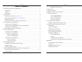
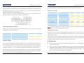
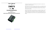
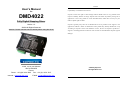
Contents
User’s Manual
For
DMD4022
Fully Digital Stepping Driver
Version 1.0
©2009 All Rights Reserved
Attention: Please read this manual carefully before using the driver!
The content in this manual has been carefully prepared and is believed to be accurate, but no
responsibility is assumed for inaccuracies.
Soprolec reserves the right to make changes without further notice to any products herein to
improve reliability, function or design. Soprolec does not assume any liability arising out of the
application or use of any product or circuit described herein; neither does it convey any license
under its patent rights of others.
Soprolec’s general policy does not recommend the use of its products in life support or aircraft
applications wherein a failure or malfunction of the product may directly threaten life or injury.
According to Soprolec’s terms and conditions of sales, the user of Soprolec’s products in life
support or aircraft applications assumes all risks of such use and indemnifies Soprolec against all
damages.
18 bis, rue du vert buisson
95470 VEMARS
France
Phone : +33 (0)6 3104 3562
Fax : +33 (0)1 3431 3917
Internet : www.soprolec.com
E-Mail : [email protected]
©2009 by Soprolec
All Rights Reserved
II
Contents
Table of Contents
1. Introduction, Features and Applications.................................................................... 1
Introduction ........................................................................................................... 1
Features ................................................................................................................. 1
Applications........................................................................................................... 1
2. Specifications ............................................................................................................ 2
Electrical Specifications (Tj = 25 /77 ) .............................................................. 2
Mechanical Specifications ( unit: mm [inch] ) ...................................................... 2
Elimination of Heat ............................................................................................... 2
Operating Environment and other Specifications.................................................. 3
3. Pin Assignment and Description ............................................................................... 3
Connector P1 Configurations ................................................................................ 3
Selecting Active Pulse Edge and Control Signal Mode......................................... 4
Connector P2 Configurations ................................................................................ 4
4. Control Signal Connector (P1) Interface ................................................................... 4
5. Connecting the Motor................................................................................................ 5
Connections to 4-lead Motors................................................................................ 5
Connections to 6-lead Motors................................................................................ 6
Half Coil Configurations ............................................................................... 6
Full Coil Configurations................................................................................ 6
Connections to 8-lead Motors................................................................................ 7
Series Connections ........................................................................................ 7
Parallel Connections...................................................................................... 7
6. Power Supply Selection............................................................................................. 7
Regulated or Unregulated Power Supply .............................................................. 8
Multiple Drivers .................................................................................................... 8
Selecting Supply Voltage....................................................................................... 8
7. Selecting Microstep Resolution and Driver Output Current ..................................... 9
Microstep Resolution Selection............................................................................. 9
Current Settings..................................................................................................... 9
I
Contents
Dynamic current setting .............................................................................. 10
Standstill current setting .............................................................................. 10
8. Wiring Notes............................................................................................................ 10
9. Typical Connection.................................................................................................. 11
10. Sequence Chart of Control Signals........................................................................ 11
11. Protection Functions .............................................................................................. 12
Over-current Protection ............................................................................... 12
Over-voltage Protection............................................................................... 12
Phase Error Protection................................................................................. 13
Protection Indications.................................................................................. 13
12. Frequently Asked Questions.................................................................................. 13
Problem Symptoms and Possible Causes ............................................................ 14
13. Professional Tuning Software ProTuner................................................................ 15
Introduction ......................................................................................................... 15
Software Installation............................................................................................ 15
Connections and Testing...................................................................................... 19
RS232 Interface Connection................................................................................ 20
Testing the Stepping System................................................................................ 20
Software Introduction.......................................................................................... 20
Com Config Window................................................................................... 21
Tuning.......................................................................................................... 21
Anti-Resonance Introduction....................................................................... 24
Procedure for Achieving Optimum Performance ........................................ 25
APPENDIX ................................................................................................................. 29
Twelve Month Limited Warranty ........................................................................ 29
Exclusions ........................................................................................................... 29
Obtaining Warranty Service ................................................................................ 29
Warranty Limitations........................................................................................... 29
II
DMD4022 Numerical stepper driver
DMD4022 Numerical stepper driver
2. Specifications
1. Introduction, Features and Applications
Introduction
Electrical Specifications (Tj = 25℃/77℉)
The DMD4022 is a versatility fully digital stepping driver based on a DSP with advanced control
algorithm. The DMD4022 is the next generation of digital stepping motor controls. It brings a
Parameters
unique level of system smoothness, providing optimum torque and nulls mid-range instability.
DMD4022
Min
Typical
Max
Unit
Motor self-test and parameter auto-setup technology offers optimum responses with different
Output current
0.3
-
2.2 (1.6 RMS)
A
motors and easy-to-use. The driven motors can run with much smaller noise, lower heating,
Supply voltage
+20
-
+40
VDC
smoother movement than most of the drivers in the markets. Its unique features make the
Logic signal current
7
10
16
mA
DMD4022 an ideal solution for applications that require low-speed smoothness. Compared to the
Pulse input frequency
0
-
75
kHz
Isolation resistance
500
DM432C, the DMD4022 has smaller size and lower cost.
Features
z Anti-Resonance, provides optimum torque
and nulls mid-range instability
z Motor self-test and parameter auto-setup
Mechanical Specifications ( unit: mm [inch] )
z Supply voltage up to +40 VDC
z Output current programmable, from 0.3A to
2.2A
technology, offers optimum responses with
z Pulse input frequency up to 75 KHz
different motors
z TTL compatible and optically isolated input
z Multi-Stepping allows a low resolution step
z Automatic idle-current reduction
input to produce a higher microstep output
z Suitable for 2-phase and 4-phase motors
for smooth system performance
z Support PUL/DIR and CW/CCW modes
z Microstep resolutions programmable, from
full-step to 102,400 steps/rev
MΩ
z Over-voltage,
over-current,
phase-error
protections
Figure 1: Mechanical specifications
Applications
Elimination of Heat
Suitable for a wide range of stepping motors, from NEMA frame size 14 to 23. It can be used in
various kinds of machines, such as laser cutters, laser markers, high precision X-Y tables, labeling
machines, and so on. Its unique features make the DMD4022 an ideal solution for applications that
require low-speed smoothness.
z
z
z
Driver’s reliable working temperature should be <70 (158 ℉ ), and motor working
temperature should be <80 (176℉);
It is recommended to use automatic idle-current mode, namely current automatically reduce
to 60% when motor stops, so as to reduce driver heating and motor heating;
It is recommended to mount the driver vertically to maximize heat sink area. Use forced
2
1
DMD4022 Numerical stepper driver
DMD4022 Numerical stepper driver
cooling method to cool the system if necessary.
ENA
Operating Environment and other Specifications
Cooling
Natural Cooling or Forced cooling
Avoid dust, oil fog and corrosive gases
Environment
0 -50
Ambient Temperature
Operating
Humidity
Environment
Operating Temperature
Weight
-20 -65
70
rising edge active.
(158℉) Max
Connector P1 Configurations
DIR
OPTO
Details
Pulse signal: In single pulse (pulse/direction) mode, this input represents pulse
signal, each rising or falling edge active (software configurable); 4-5V when
PUL-HIGH, 0-0.5V when PUL-LOW. In double pulse mode (pulse/pulse) ,
this input represents clockwise (CW) pulse,active both at high level and low
level (software configurable). For reliable response, pulse width should be
longer than 7.5µs. Series connect resistors for current-limiting when +12V or
+24V used. The same as DIR and ENA signals.
DIR signal: In single-pulse mode, this signal has low/high voltage levels,
representing two directions of motor rotation; in double-pulse mode (software
configurable), this signal is counter-clock (CCW) pulse,active both at high
level and low level (software configurable). For reliable motion response, DIR
signal should be ahead of PUL signal by 5µs at least. 4-5V when DIR-HIGH,
0-0.5V when DIR-LOW. Please note that rotation direction is also related to
motor-driver wiring match. Exchanging the connection of two wires for a coil
to the driver will reverse motion direction.
Opto-coupler power supply, and the typical voltage is +5V. Series connect
resistors (at the PUL, DIR, ENA terminals) for current-limiting when +12V or
+24V used.
3
Connector P2 Configurations
(-4℉-149℉)
Approx. 100g (3.5274oz)
The DMD4022 has two connectors, connector P1 for control signals connections, and connector
P2 for power and motor connections. The following tables are brief descriptions of the two
connectors. More detailed descriptions of the pins and related issues are presented in section 4, 5,
9.
PUL
The DMD4022 supports PUL/DIR and CW/CCW modes and pulse active at rising or falling edge.
See more information about these settings in Section 13. Default setting is PUL/DIR mode and
3. Pin Assignment and Description
Pin Function
Selecting Active Pulse Edge and Control Signal Mode
40%RH-90%RH
5.9m/s2 Max
Vibration
Storage Temperature
(32℉-122℉)
Enable signal: This signal is used for enabling/disabling driver. High level for
enabling the driver and low level for disabling the driver. Usually left
UNCONNECTED (ENABLED).
Pin Function
Details
+Vdc
Power supply, 20~40 VDC, Including voltage fluctuation and EMF voltage.
GND
Power Ground.
A+, A-
Motor Phase A
B+, B-
Motor Phase B
4. Control Signal Connector (P1) Interface
The DMD4022 uses opto-couplers to increase noise immunity and interface flexibility. If the
opto-couplers’ supply voltage is higher than +5V, a current-limiting resistor needs to be
connected at each command signal terminal to prevent overheating the opto-couplers. In the
following figures, connections to open-collector and differential controller are illustrated.
4
DMD4022 Numerical stepper driver
DMD4022 Numerical stepper driver
Figure 4: 4-lead Motor Connections
Connections to 6-lead Motors
Like 8 lead stepping motors, 6 lead motors have two configurations available for high speed or
high torque operation. The higher speed configuration, or half coil, is so described because it uses
one half of the motor’s inductor windings. The higher torque configuration, or full coil, uses the
full windings of the phases.
Half Coil Configurations
Figure 2: Connections to open-collector signal (common-anode)
As previously stated, the half coil configuration uses 50% of the motor phase windings. This gives
lower inductance, hence, lower torque output. Like the parallel connection of 8 lead motor, the
torque output will be more stable at higher speeds. This configuration is also referred to as half
chopper. In setting the driver output current multiply the specified per phase (or unipolar) current
rating by 1.4 to determine the peak output current.
Figure 5: 6-lead motor half coil (higher speed) connections
Full Coil Configurations
Figure 3: Connections to differential control signal
5. Connecting the Motor
The full coil configuration on a six lead motor should be used in applications where higher torque at
lower speeds is desired. This configuration is also referred to as full copper. In full coil mode, the
motors should be run at only 70% of their rated current to prevent over heating.
The DMD4022 can drive any 2-pahse and 4-pahse hybrid stepping motors.
Connections to 4-lead Motors
4 lead motors are the least flexible but easiest to wire. Speed and torque will depend on winding
inductance. In setting the driver output current, multiply the specified phase current by 1.4 to
determine the peak output current.
5
Figure 6: 6-lead motor full coil (higher torque) connections
6
DMD4022 Numerical stepper driver
Connections to 8-lead Motors
8 lead motors offer a high degree of flexibility to the system designer in that they may be
connected in series or parallel, thus satisfying a wide range of applications.
Series Connections
A series motor configuration would typically be used in applications where a higher torque at lower
speeds is required. Because this configuration has the most inductance, the performance will start to
degrade at higher speeds. In series mode, the motors should also be run at only 70% of their rated
current to prevent over heating.
Figure 7: 8-lead motor series connections
Parallel Connections
An 8 lead motor in a parallel configuration offers a more stable, but lower torque at lower speeds.
But because of the lower inductance, there will be higher torque at higher speeds. Multiply the per
phase (or unipolar) current rating by 1.96, or the bipolar current rating by 1.4, to determine the
peak output current.
DMD4022 Numerical stepper driver
determines the output torque of the driven motor (particularly at lower speed). Higher supply
voltage will allow higher motor speed to be achieved, at the price of more noise and heating. If the
motion speed requirement is low, it’s better to use lower supply voltage to decrease noise, heating
and improve reliability.
Regulated or Unregulated Power Supply
Both regulated and unregulated power supplies can be used to supply the driver. However,
unregulated power supplies are preferred due to their ability to withstand current surge. If
regulated power supplies (such as most switching supplies.) are indeed used, it is important to
have large current output rating to avoid problems like current clamp, for example using 4A
supply for 3A motor-driver operation. On the other hand, if unregulated supply is used, one may
use a power supply of lower current rating than that of motor (typically 50%~70% of motor
current). The reason is that the driver draws current from the power supply capacitor of the
unregulated supply only during the ON duration of the PWM cycle, but not during the OFF
duration. Therefore, the average current withdrawn from power supply is considerably less than
motor current. For example, two 3A motors can be well supplied by one power supply of 4A
rating.
Multiple Drivers
It is recommended to have multiple drivers to share one power supply to reduce cost, if the supply
has enough capacity. To avoid cross interference, DO NOT daisy-chain the power supply input
pins of the drivers. Instead, please connect them to power supply separately.
Selecting Supply Voltage
The power MOSFETs inside the DMD4022 can actually operate within +20 ~ +40VDC, including
power input fluctuation and back EMF voltage generated by motor coils during motor shaft
Figure 8: 8-lead motor parallel connections
NEVER disconnect or connect the motor while the power source is energized.
deceleration. Higher supply voltage can increase motor torque at higher speeds, thus helpful for
avoiding losing steps. However, higher voltage may cause bigger motor vibration at lower speed,
and it may also cause over-voltage protection or even driver damage. Therefore, it is suggested to
choose only sufficiently high supply voltage for intended applications, and it is suggested to use
6. Power Supply Selection
The DMD4022 can match medium and small size stepping motors (from NEMA frame size 14 to
23) made by Soprolec or other motor manufactures around the world. To achieve good driving
performances, it is important to select supply voltage and output current properly. Generally
speaking, supply voltage determines the high speed performance of the motor, while output current
7
power supplies with theoretical output voltage of +20 ~ +36VDC, leaving room for power
fluctuation and back-EMF.
8
DMD4022 Numerical stepper driver
DMD4022 Numerical stepper driver
When it’s not in software configured mode, the first three bits (SW1, 2, 3) of the DIP switch are
7. Selecting Microstep Resolution and Driver Output Current
Microstep resolutions and output current are programmable, the former can be set from full-step to
102,400 steps/rev and the latter can be set from 0.3A to 2.2A. See more information about
used to set the dynamic current. Select a setting closest to your motor’s required current.
Dynamic current setting
Microstep and Output Current Setting in Section 13.
Peak Current
However, when it’s not in software configured mode, this driver uses a 6-bit DIP switch to set
Default/Software configured (0.3 to 2.2A)
microstep resolution, and motor operating current, as shown below:
Microstep Resolution Selection
When it’s not in software configured mode, microstep resolution is set by SW5, 6 of the DIP
RMS Current
SW1
SW2
SW3
ON
ON
ON
0.5A
0.35 A
OFF
ON
ON
0.7A
0.50 A
ON
OFF
ON
1.0A
0.71 A
OFF
OFF
ON
1.3A
0.92 A
ON
ON
OFF
1.6A
1.13 A
OFF
ON
OFF
1.9A
1.34 A
ON
OFF
OFF
2.2A
1.56 A
OFF
OFF
OFF
Notes: Due to motor inductance, the actual current in the coil may be smaller than the dynamic
current setting, particularly under high speed condition.
Standstill current setting
switch as shown in the following table:
Microstep
Steps/rev.(for 1.8°motor)
SW5
SW6
1 to 512
Default/Software configured
ON
ON
8
1600
OFF
ON
16
3200
ON
OFF
32
6400
OFF
OFF
SW4 is used for this purpose. OFF meaning that the standstill current is set to be half of the
selected dynamic current, and ON meaning that standstill current is set to be the same as the
selected dynamic current.
The current automatically reduced to 60% of the selected dynamic current one second after the last
pulse. Theoretically, this will reduce motor heating to 36% (due to P=I2*R) of the original value. If
the application needs a different standstill current, please contact Soprolec.
Current Settings
8. Wiring Notes
For a given motor, higher driver current will make the motor to output more torque, but at the
z
In order to improve anti-interference performance of the driver, it is recommended to use
twisted pair shield cable.
z
To prevent noise incurred in PUL/DIR signal, pulse/direction signal wires and motor wires
should not be tied up together. It is better to separate them by at least 10 cm, otherwise the
disturbing signals generated by motor will easily disturb pulse direction signals, causing
motor position error, system instability and other failures.
z
If a power supply serves several drivers, separately connecting the drivers is recommended
same time causes more heating in the motor and driver. Therefore, output current is generally set
to be such that the motor will not overheat for long time operation. Since parallel and serial
connections of motor coils will significantly change resulting inductance and resistance, it is
therefore important to set driver output current depending on motor phase current, motor leads and
connection methods. Phase current rating supplied by motor manufacturer is important in selecting
driver current, however the selection also depends on leads and connections.
9
10
DMD4022 Numerical stepper driver
DMD4022 Numerical stepper driver
instead of daisy-chaining.
z
It is prohibited to pull and plug connector P2 while the driver is powered ON, because there
is high current flowing through motor coils (even when motor is at standstill). Pulling or
plugging connector P2 with power on will cause extremely high back-EMF voltage surge,
which may damage the driver.
9. Typical Connection
A complete stepping system should include stepping motor, stepping driver, power supply and
controller (pulse generator). A typical connection is shown as figure 9.
Figure 10: Sequence chart of control signals
Remark:
a)
t1: ENA must be ahead of DIR by at least 5µs. Usually, ENA+ and ENA- are NC (not
connected). See “Connector P1 Configurations” for more information.
b)
t2: DIR must be ahead of PUL effective edge by 5µs to ensure correct direction;
c)
t3: Pulse width not less than 7.5µs;
d)
t4: Low level width not less than 7.5µs.
11. Protection Functions
To improve reliability, the driver incorporates some built-in protection functions. The DMD4022
Figure 9: Typical connection
uses one RED LED to indicate what protection has been activated. The periodic time of RED is 3
s (seconds), and how many times the RED turns on indicates what protection has been activated.
10. Sequence Chart of Control Signals
Because only one protection can be displayed by RED LED, so the driver will decide what error to
In order to avoid some fault operations and deviations, PUL, DIR and ENA should abide by some
rules, shown as following diagram:
display according to their priorities. See the following Protection Indications table for displaying
priorities.
Over-current Protection
Over-current protection will be activated when continuous current exceeds 16A or in case of short
circuit between motor coils or between motor coil and ground, and RED LED will turn on once
within each periodic time (3 s).
Over-voltage Protection
When power supply voltage exceeds 42±1 VDC, protection will be activated and RED LED will
11
12
DMD4022 Numerical stepper driver
DMD4022 Numerical stepper driver
turn on twice within each periodic time (3 s).
Phase Error Protection
Motor power lines wrong & not connected will activate this protection. RED LED will turn on
four times within each periodic time (3 s).
Attention: When above protections are active, the motor shaft will be free or the LED will turn
red. Reset the driver by repowering it to make it function properly after removing above problems.
Since there is no protection against power leads (﹢,﹣) reversal, it is critical to make sure that power
supply leads correctly connected to driver. Otherwise, the driver will be damaged instantly.
Protection Indications
Priority
Time(s) of ON
Sequence wave of RED LED
Description
1st
1
Over-current protection
2nd
2
Over-voltage protection
3rd
4
Phase error protection
Problem Symptoms and Possible Causes
12. Frequently Asked Questions
Symptoms
Possible Problems
In the event that your driver doesn’t operate properly, the first step is to identify whether the
No power
problem is electrical or mechanical in nature. The next step is to isolate the system component that
Microstep resolution setting is wrong
is causing the problem. As part of this process you may have to disconnect the individual
Motor is not rotating
DIP switch current setting is wrong
components that make up your system and verify that they operate independently. It is important to
Fault condition exists
document each step in the troubleshooting process. You may need this documentation to refer back
to at a later date, and these details will greatly assist our Technical Support staff in determining the
problem should you need assistance.
Many of the problems that affect motion control systems can be traced to electrical noise,
controller software errors, or mistake in wiring.
The driver is disabled
Motor rotates in the wrong direction
The driver in fault
Motor phases may be connected in reverse
DIP switch current setting is wrong
Something wrong with motor coil
Control signal is too weak
Erratic motor motion
Control signal is interfered
Wrong motor connection
13
14
DMD4022 Numerical stepper driver
Something wrong with motor coil
Current setting is too small, losing steps
DMD4022 Numerical stepper driver
Double click “ProTuner_DMD4022.exe” to begin installing the ProTuner. See Figure 11. Click
Next to enter the “License Agreement” window. See Figure 12.
Current setting is too small
Motor stalls during acceleration
Motor is undersized for the application
Acceleration is set too high
Power supply voltage too low
Inadequate heat sinking / cooling
Excessive motor and driver heating
Automatic current reduction function not being utilized
Current is set too high
Figure 11: Begin to install the ProTuner
13. Professional Tuning Software ProTuner
Introduction
This section will provide an overview of connection and basic setup instructions for Soprolec’s
digital stepping driver DMD4022 using the ProTuner software. These instructions will walk you
through the following steps necessary to start up your driver and motor. This section is intended for
setting up the driver with the ProTuner.
Figure 12: License agreement
Software Installation
The ProTuner is windows based setup software for tuning Soprolec’s digital stepper driver
DMD4022. It can run in windows systems, including Win95/Win98/WindowsNT/ Windows
2000/Windows XP. And the selected PC should have 1 serial port at least for communicating with
Choose “I agree to the terms of this license agreement” and click Next to continue installation. The
user can enter user’s information in the following window. See Figure 13. After entering the user’s
information, click Next to select installation folder, where you would like to install the ProTuner.
See Figure 14.
the driver.
15
16
DMD4022 Numerical stepper driver
DMD4022 Numerical stepper driver
Figure 13: User’s information settings
Figure 15: Shortcut folder setting
Set the “Shortcut Folder” in Figure 15 and continue to install the ProTuner by following Figure 16
and Figure 17. An Installation Successful window will appear if the ProTuner is installed
successfully. See Figure 18.
Figure 14: Installation folder settings
Figure 16: Installation information summarization
17
18
DMD4022 Numerical stepper driver
DMD4022 Numerical stepper driver
RS232 Interface Connection
DM422C
Figure 19: RS232 interface connection
Testing the Stepping System
Figure 17: Installing the ProTuner
Turn on the power supply, the green (Power) LED will light. The DMD4022 has default
parameters stored in the driver. If the system has no hardware and wirings problem, the motor
should be locked and the driver should be ready.
If the red LED immediately turns on (flickers), then check power supply, the motor, motor wirings
and try again. Open the tuning software ProTuner and check driver status by clicking Err_check.
If it’s Phase Error, check the motor, motor wirings and try again. If it still doesn’t work after you
followed all of the previous steps, please contact us at [email protected].
If the RED LED is OFF and the motor is normal, then you can start to tune the servo with
ProTuner. However, we recommend you see the following contents before starting tuning.
Figure 18: Finish installation
Connections and Testing
Software Introduction
¾
Option
Connect the stepping system according to the contents in previous sections and connect the PC to
The user can choose three drop-down menus by clicking “Option”, including Com Config,
the driver as the following figure.
SaveToDriver and Exit.
19
z
Com Config: Configure Com communication interface.
z
SaveToDriver: Download the current parameter settings to the driver.
z
Exit: Exit the ProTuner.
20
DMD4022 Numerical stepper driver
DMD4022 Numerical stepper driver
Com Config Window
Figure 21: RS232 communication configuration window
Figure 22: Current Tuning window
Serial Port: Select the serial communication port to which the driver is connected. The factory
default setting is COM1.
Ki: Integral Gain. Integral Gain helps the driver to overcome static current errors. A low or zero
Baud Rate: Select the communication baud rate. The factory default setting is 38400.
value for the Integral Gain may have current errors at rest. Increasing the Integral Gain can reduce
Click Open button to establish a connection with the specified settings. When connecting, you can
choose SaveToDrive to download the current parameter settings to the driver, or to upload the
stored driver settings into the ProTuner by clicking Tuning > Position Loop on the menu bar.
the error. If the Integral Gain is too large, the systems may “hunt” (oscillate) about the desired
position.
Start button: The user can start a Step Response test by clicking this button. Start/Restart a Step
Response test to get an optimum response like Figure 22, and remember to save the settings to the
Tuning
The user can choose one or two drop-down menu(s) by clicking Tuning, including CurrentLoop
driver when finish tuning. See Figure 24.
and SystemConfig.
z
CurrentLoop: In Current Tuning window, the user can tune the Kp (Proportional Gain) and
Ki (Integral Gain) of driver’s current loop to optimize responses with different motors.
Start/Restart a Step Response test to get an optimum response.
Kp: Proportional Gain. Proportional Gain determines the response of the driver to current setting
command. Low Proportional Gain provides a stable system (doesn’t oscillate), has low stiffness, and
large current error, causing poor performances in tracking current setting command in each step like
Figure 23. Too large Proportional Gain values will cause oscillations and unstable systems.
21
Figure 23: Kp=2346, Ki=0 (poor performances)
22
DMD4022 Numerical stepper driver
DMD4022 Numerical stepper driver
CommandType: Command Type of control signal, including PUL/DIR and CW/CCW. Set this
parameter according to Command Type of motion controller.
ActiveEdge: Active Edge. The user can set the triggered edge of pulse command signal in this panel.
When the driver works in CW/CCW mode, no matter what level is at fixed level terminal, the driver
can works properly.
Anti-Resonance Introduction
Step motors are highly resonant, which results in vibration and ringing. The ringing utilizes a large
Figure 24: Finish tuning and save setting to the driver
fraction of the motor's available torque – thereby wasting performance. Furthermore, at mid-range
Notes:
velocities, the resonance can become so severe that the motor looses synchronization and stalls. The
However, if the user does not want to tune the current loop after changing a different stepping motor,
DMD4022 driver provides robust anti-resonance control to stop the vibrations and maintain
then Motor self-test and parameter auto-setup technology of the DMD4022 can replace manual
equilibrium. This feature requires that the driver be configured with respect to the total inertia in the
tuning the driver with ProTuner. Just changes SW4 two times in 1 second, and then the driver will
system. If set improperly, the effectiveness of the feature may be diminished.
auto-identify the new motor and auto-configure related control parameters for optimum responses.
The user can invoke or disable the feature by setting Amp and Phase values in SystemConfig
Recommend use this function after changing the driven motor.
window. Amp and Phase values all zero is to disable the feature, otherwise is to invoke the feature.
z
It should be enabled unless the system configuration either does not need it or cannot tolerate it. A
SystemConfig:
system with loose couplings or viscous loading generally does not need this feature. If a system has
In SystemConfig window, the user can configure Peak Current, Microstep, Command Type, Active
Edge, and eliminate motor resonance. A built-in pulse generator can be used for test during tuning.
See Picture 25.
compliant (springy) coupling and is absent appreciably viscosity, it may not respond well to the
th
active, anti-resonant loop in the drive. The anti-resonant feature is not designed to damp such a 4
order system. If the application of anti-resonance results in degradation or instability, it should be
PeakCur: Peak Current. The value is the peak current to the selected motor and can be set from
disabled.
0.1 to 3.2 A. The user can set the peak current with ProTuner or DIP switches, see more
information about setting output current of the driver in section 5 “Connecting the Motor” and
section 7 “Selecting Microstep Resolution and Driver Output Current”.
MicroStep: Microstep Resolution. The value is driver’s microstep resolution setting and can be set
from 1 to 512. The user can set the microstep with ProTuner or DIP switches, See more information
about setting output current of the driver in section 7 “Selecting Microstep Resolution and Driver
1st ResonanceArea: Parameters for 1st resonance area. Usually between 0.6rps and 1.2rps.
Amp1 is Amplitude adjustment for 1st resonance area.
Phase1 is Phase adjustment for 1st resonance area. The user can enter a value directly in the text box
or move the slider bar back and forth to get an optimum value.
LowerLimit is the Lower Limit of the 1st resonance area, and the user can capture this value when
finds it during move the slider bar of internal pulse generator.
Output Current”.
UpperLimit is the Upper Limit of the 1st resonance area. Default Amp1 and Phase1 values are
StepAngle: Step Angle. The driver will auto detect the Step Angle of the driven motor.
23
zero.
24
DMD4022 Numerical stepper driver
nd
2
nd
ResonanceArea: Parameters for 2
resonance area. Usually between 1.2rps and 2.4rps.
Default Amp2 and Phase2 values are zero.
DMD4022 Numerical stepper driver
better smoothing value by slightly moving the slider bars of AMP(s) and Phase(s) back and forth.
It is very important to make the AMP(s) and Phase(s) adjustments at the proper test speeds with an
3rd ResonanceArea: Parameters for 3rd resonance area. Usually between 2.4rps and 4.8rps.
Default Amp3 and Phase3 values are 128.
unloaded motor. Running at an incorrect test speed will not excite the motor at its peak resonance,
making it more difficult to find proper adjustment values. Optimum AMP(s) and Phase(s) values
may be a little different between running the tests with an unloaded motor and a load motor.
Start/Stop button: The user can start/Stop a motion test by clicking this button.
Please remember to click SavetoDrive to download the final parameter settings to the driver when
finish tuning. See Figure 27.
Figure 25: SystemConfig window
Figure 26: Anti-resonance tuning
Procedure for Achieving Optimum Performance
Step 1: Start the motion test by clicking Start/Stop button. Find the Lower Limit values and Upper
Limit values for each resonance area by slightly moving the slider bar of internal pulse generator
back and forth, and capture these values for anti-resonance algorithm by clicking Capture buttons.
See Figure 26.
Step 2: Run the motor at the given test speed and verify the motor smoothness. You may find a
25
26
DMD4022 Numerical stepper driver
DMD4022 Numerical stepper driver
OverCurrent: Over-current Protection. Protection will be activated when continuous current
exceeds 16A.
OverVoltage: Over-voltage Protection. When power supply voltage exceeds 42 ± 1 VDC,
protection will be activated.
PhaseErr: Phase Error Protection. Motor power lines wrong & not connected will activate this
protection.
ErrCounter: Displays current error(s) and current error history.
Erase Current Err!: Erase Current Err button. The user can clear current error(s) by clicking this
button.
Erase All!: Erase All! button. The user can clear all error(s) including error history by clicking this
button.
¾
About
The user can choose two drop-down menus by clicking “About”, including Product Information
and Contact Us.
z
Product Information window: Shows some product information about ProTuner.
Figure 27: Finishing tuning and download parameter settings to the driver
¾
Err_check
z
Error Check: This window shows both the present status of each error event and their history.
Current error event(s) can be reset by clicking Erase Current Err! button, and all error events
can be reset by clicking Erase All! button. List of the last ten drive faults. #0 being the most
recent, #9 is the oldest. See Figure 28.
Figure 28: Error check window
27
28
DMD4022 Numerical stepper driver
APPENDIX
Twelve Month Limited Warranty
SOPROLEC. warrants its products against defects in materials and workmanship for a period of
12 months from shipment out of factory. During the warranty period, Soprolec will either, at its
option, repair or replace products which proved to be defective.
Exclusions
The above warranty does not extend to any product damaged by reasons of improper or inadequate
handlings by customer, improper or inadequate customer wirings, unauthorized modification or
misuse, or operation beyond the electrical specifications of the product and/or operation beyond
environmental specifications for the product.
Obtaining Warranty Service
To obtain warranty service, a returned material authorization number (RMA) must be obtained
from customer service at e-mail: [email protected] before returning product for service.
Customer shall prepay shipping charges for products returned to Soprolec for warranty service,
and Soprolec shall pay for return of products to customer.
Warranty Limitations
Soprolec makes no other warranty, either expressed or implied, with respect to the product.
Soprolec specifically disclaims the implied warranties of merchantability and fitness for a
particular purpose. Some jurisdictions do not allow limitations on how long and implied warranty
lasts, so the above limitation or exclusion may not apply to you. However, any implied warranty of
merchantability or fitness is limited to the 12-month duration of this written warranty.
Shipping Failed Product
If your product fail during the warranty period, e-mail customer service at [email protected]
to obtain a returned material authorization number (RMA) before returning product for service.
Please include a written description of the problem along with contact name and address. Send
failed product to: Soprolec – 18 bis, rue du vert Buisson – F95470. Also enclose information
regarding the circumstances prior to product failure.
29