1
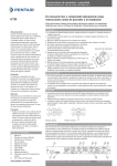
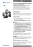
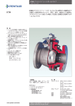
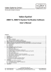
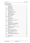
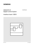
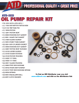
KTM OM-2 Split Body Floating Ball Valves (Soft seat - Gratite seat - Metal seat)
Installation and Maintenance Instructions
KTM
Section 1 - Storage
1.1. Preparation and preservation for storage
All valves should be properly packed in order to protect the parts that are subject to deterioration
during transportation and storage on site. In particular, the following precautions should be taken:
• The valves must be packed with the ball in the open position.
• The flange sealing surface (raised face) shall be protected with suitable protective oil.
• The end faces of the valve must be protected with appropriate seal discs.
• The type of packing must be defined in the Customer’s Order and be appropriate to ensure safe
transportation to the final destination and eventual storage before installation. Wrapping and/or
covers should be left in place until just prior to installation.
1.2. Handling requirements
1.2.1. Packed valves
Crates:Appropriate crate handling equipment should be used to prevent damage to crated
valves.
Boxes:Handling of valves packed in carton boxes should be done with extra caution, taking
specific note to lifting points and the center of gravity.
The transportation of all packed valves and components must be carried out safely and in
accordance with all local safety regulations. Pay particular attention to the lifting limits of
handling equipment with reference to the overall weight of packed and unpacked valves.
1.2.2. Unpacked valves
• The handling of valves unpacked from its original packing needs to be carried out with
additional exterior protection in order to avoid damages to machined surfaces. Use pallets at
all times, where appropriate.
• When handling large valves, appropriate tools (brackets, hooks, fasteners, ropes) should
be used to secure valves firmly; and lifting loads should be balanced in order to prevent the
valves from falling or moving during the handling process.
Caution
• When handling valves, the correct equipment and accessories (slings, fasteners, hooks,
etc.) must be sized and selected, taking into consideration the individual and/or overall
valves weight indicated in the packing list and/or delivery note.
• Lifting and handling must be made only by qualified personnel. Improper hoisting can
cause valve deformation or damage from dropping the valve.
• Do not lift valves by using lifting points or lugs located on the actuator as these lifting
points/lugs are for the actuator only.
• Do not lift the valve by its hand-lever as these levers are not designed to take the load of
the whole valve. Doing so may cause the lever to break off or be disconnected from the
valve, resulting in possible valve damage or injury.
• Avoid lifting over a worker’s head or equipment, or any other thing that can possibly
be damaged or cause of injury in the event that the lifted load falls off the handling
equipment.
• All local safety regulations must be observed and complied with at all times.
1.3. Storage and preservation before installation
The storage of the valves should be in accordance with the following criteria:
• Storage room should be clean and dry.
• The ball must be in the open position and the end faces must be protected with appropriate seal
discs.
• Periodical checks have to be carried out in the storage area to verify that the above mentioned
conditions are maintained.
Caution
The ball valves are delivered with the ball in the full-open position and should be stored as
they are. Keeping the ball in other positions or half-open position for an extended period of
time could cause seat leakage.
Note
• Do not place consignment package directly on the ground.
• Do not expose consignment packages to the rain/wind or directly to the sun.
• Storage in an open area for a limited period can be considered only if the valves have appropriate
packing (packed in cases covered with vinyl sheets protecting from rain, wind, dust etc, and
contents well protected with barrier sacks).
• Store in a dry and well ventilated condition.
• If storage is anticipated for an extended period, the desiccant bags (if supplied) should be
changed every 6 months.
www.pentair.com/valves
Pentair reserves the right to change the contents without notice
KTMWY-0002-EN-1306
KTM OM-2 Split Body Floating Ball Valves (Soft seat - Gratite seat - Metal seat)
Installation and Maintenance Instructions
Section 2 - Installation
2.1. Preparation before installation
• Remove the valve from the shipping package (box or pallet) with care taken to avoid any damage
to the valve and actuator (plus accessories where applicable).
• Before installation, remove the seal discs from the flange. Clean the inside of the valve using
an air line that includes an appropriate air-filter. Ensure that there are no solid objects such as
pieces of wood, plastic or packing materials within the valve or on the valve seat.
• Confirm that the materials of construction listed on the valve nameplates are appropriate for
the service intended for and are as specified. When in doubt contact KTM, or your local Pentair
facility.
• Define the preferred mounting orientation with respect to the system pressure. The arrow on the
body helps to identify the upstream side (high pressure) and downstream side (low pressure).
• Ensure that all stud bolts and nuts of the body joint are firmly fastened.
Caution
• Verify that the direction of the flow in the line corresponds to the arrow indicated on the
valve body. Valves without the arrow are bi-directional.
• See the Actuator User Manual for the actuator preparation.
2.2. Installation Instructions
• Ball valves are normally installed in horizontal pipes with the stem facing up. However, there are
no limitations regarding the pipe or stem orientation.
• Unless otherwise recommended by KTM, the valve should be installed with the ball in the open
position, to ensure that the seat rings are not damaged during installation.
• Particular care should be taken for valves equipped with “fail-close” actuators.
• For operating temperatures above 200°C (392°F), thermal insulation of the valve body is
recommended to protect the actuator/accessories from heat beyond the recommended
temperature range.
• Handling and lifting of the valves during installation MUST be performed following the same
criteria and instructions described in points 1.2. and 1.3.
Important
• It is recommended to perform pipe flushing before installation of the valve. If this is not
possible, the installed valve must be in its open position before flushing takes place.
• When conducting pressure test of the pipe system, the valve should be in a full or half
open position. Check for any leakage from the joint flange and gland portion during the
pressure test.
• If the piping system is pressurized with water for testing, and if the piping system has
been shut down for a long time after testing, the following recommendation should be
adopted:
1. Use corrosion inhibitor with water to pressurize the piping system.
2. After testing, the piping system should be depressurized and the test water
completely drained.
3. Ensure that the corrosion inhibitor does not leave a residue within the system as the
particulates may damage the valve sealing surfaces.
Caution
During the pipe system pressure test, care must be taken not to set the valve in the closed
position to avoid overload pressure which may cause seat deformation or seat leakage.
2.3. Valve verification before start-up
• Tighten the gland nut just enough to prevent stem leakage. Over-tightening will decrease
packing life and increase operating torque. There is no need to over-tighten the stud bolts/nuts
to assure gasket tightness.
• Check the operation of the valve by stroking it to “full open” and “full close”. The valve ball
travels clockwise to close.
Pentair reserves the right to change the contents without notice
page 2
KTM OM-2 Split Body Floating Ball Valves (Soft seat - Gratite seat - Metal seat)
Installation and Maintenance Instructions
Section 3 - Operation instructions
Either the hand lever or the direction of the parallel flats on the top of the stem indicate the open
or closed position of the KTM ball valve. For gear operated valves, the position is indicated by the
arrow-indicator (see picture).
Open position
Excessive over travel during handle operation may break the lever, injure the operator, and/or
deform the stopper or the stem, which may lead to seat leakage.
The following instructions will help provide a satisfactory and long life service.
1. Perform periodic valve verification.
2.In the case of actuated valves, always follow the specific instructions given by the actuator’s
manufacturer.
3.Never change the setting of torque and/or limit switches set during the final test by the
manufacturer.
4.Never change the setting of the mechanical stops of the gearbox.
Closed position
Adjustment Screws
Locking device (option)
A locking device can be provided to prevent unauthorized operation.
Lock pin dimensions (options)
Indicator
Valve nominal diameter Unit: mm
Pin dimensions
Nominal pad lock
(full bore)
L
d
diameter alpha number
15 - 25
40 - 50
65 - 100
150 - 200
25
31
39
-
4,9
6,5
8
-
1,000 - 25 m/m
1,000 - 25 m/m
1,000 - 25 m/m
1,000 - 25 m/m
Lock
Section 4 - Maintenance
No routine maintenance is required other than periodic inspection to ensure satisfactory operation.
4.1. Gland packing maintenance
If leakage is observed through the gland packing, tighten the gland nuts slowly and evenly until
the leakage stops. Do not over-tighten the packing gland nuts. Over-tightening will increase the
torque required to operate the valve. Follow the torque table to ensure correct torque used when
tightening the gland nut.
Tightening torque for body joint and gland
Body joint
Gland
Class
150
Packing material
300
RTFE or Soft carbon
Valve size
150 and 300
PTFE
Soft carbon
2
2
3
7
7
16
16
19
19
32
4
4
6
15
15
30
30
40
40
65
Standard tightening torque* (Nm)
(mm)
(inch)
Bolt size
15
20
25
40
50
65
80
100
150
200
1/2”
3/4”
1”
1 1/2”
2”
2 1/2”
3”
4”
6”
8”
M8
M8
M10
M8
M10
M12
M12
M14
M16
M20
13 - 18
13 - 18
27 - 35
13 - 18
27 - 35
49 - 54
49 - 54
75 - 86
118 - 131
220 - 270
Bolt size
18 - 23
18 - 23
36 - 46
36 - 46
61 - 77
93 - 123
93 - 123
148 - 187
385 - 488
492 - 625
M8
M8
M10
M10
M12
M14
M14
M16
M22
M24
* Standard for Soft (E) seat, Gratite seat and Metal seat
Pentair reserves the right to change the contents without notice
page 3
KTM OM-2 Split Body Floating Ball Valves (Soft seat - Gratite seat - Metal seat)
Installation and Maintenance Instructions
Replace the gland packing as and when necessary.
• Remove the lever or gear operator, snap ring and stopper.
• Remove the gland bolts and flange.
• Replace the gland packing.
Reverse the procedure.
Gland bolt
Gland flange
Gland packing
Gland bolt
Stopper
Stem
Snap ring
EB11 - 15 mm - 100 mm
EB12 - 15 mm - 100 mm
Stopper
Gland bolt
Gland bolt
Stopper
Gland flange
Gland cover
Gland packing
Stem
EB11 - 150 mm - 200 mm
EB12 - 150 mm - 200 mm
EB21 - 150 mm - 250 mm
EB22 - 150 mm - 250 mm
4.2. Body seal maintenance
Any sign of leakage through the body joint seal should be addressed immediately by tightening the
stud nuts until the leakage stops. Follow the torque table to ensure the correct torque is used when
tightening the gland nut.
Gasket
Caution
Before removing the valve from the piping, ensure that the system has been fully
depressurized and any dangerous fluids have been drained off. Failure to do so may cause
serious personal injury and/or damage to the valve.
4.3. Valve disassembly
Refer to the respective construction drawing(s) on the following page(s) of the valve(s) when
disassembling. Numbers of parts vary slightly depending on the valve size, but the basic structures
are identical.
The valve shall be in the half open position.
• Before disassembling the valve, ensure that it has been decontaminated from any harmful
gasses or fluids and is within a safe temperature range for maintenance.
• Rotate the ball to a closed position.
• Loosen the hexagon nuts and remove the body cap from the body. The seat and gasket can then
be easily removed.
• Remove the ball and seat with care so as to prevent damage to the seal face of the ball.
• Remove the snap ring of the stem with a pair of pincers and remove the gland bolts. Tap the
stem head with a plastic hammer and withdraw it towards the interior of the body.
Note
The stem has been designed as “anti-blow out” to improve safety during system operation. This
means that the stem cannot be removed from the valve body through the top of the body. It must
be removed from within the valve body.
Pentair reserves the right to change the contents without notice
page 4
Bolt
Nut
KTM OM-2 Split Body Floating Ball Valves (Soft seat - Gratite seat - Metal seat)
Installation and Maintenance Instructions
Stem
Stem bearing
Thrust bearing
4.4. Valve re-assembly
This work shall be carried out by reversing the aforementioned disassembling procedure. Further,
the following points should be noted:
• As shown in the diagram, slip a stem bearing over the stem; set in such a way so that it does not
detach from the stem. Then insert it into the gland from the interior of the body.
• Insert the gland packing (see 4.1.) and tighten the gland bolts lightly.
• Since old gaskets occasionally adhere to the body and body cap when the valve is disassembled,
the wastes of old gaskets should be completely scraped off and the sealing surfaces should be
cleaned before fitting new gaskets.
• When inserting the ball into the valve body, hold the stem in the “SHUT” position as in the case
of disassembling and perform insertion in the reversed manner for disassembling.
• Tighten the body cap with the ball in the “SHUT” position. Nuts which face each other
are diagonally and uniformly tightened with equal strength, taking care to avoid one-sided
tightening.
• Exercise care in re-assembling the valve because its opening and closing vary depending upon
whether the correct facing of the stopper (indicating OPEN and CLOSE) is well-set upwards.
• Check the valve operation torque under no load in a dry form before pressure test. Ensure that
the measured torque is within range of the standard torque table. In the event the torque is more
than the standard torque for Metal and Gratite seated ball valves, reduce the torque by adding an
extra gasket for the body joint.
Valve torque after assembly
Class
150 & 300
Seat
Soft (E)
Gland Packing
PTFE
Soft carbon
Valve size
Gratite
PTFE or Soft carbon
Metal
PTFE or Soft carbon
Standard valve torque* (Nm)
(mm)(inch)
15
20
25
40
50
65
80
100
150
200
1/2”
3/4”
1”
1 1/2”
2”
2 1/2”
3”
4”
6”
8”
2 - 6
3 - 8
3 - 9
6 - 16
8 - 22
14 - 40
20 - 60
37 - 110
104 - 310
167 - 500
5 - 10
6 - 12
8 - 14
19 - 29
21 - 35
39 - 65
45 - 85
76 - 149
170 - 374
265 - 598
max 15
max 19
max 23
max 38
max 55
max 88
max 125
max 225
max 525
max 1000
max 7
max 7
max 11
max 20
max 25
max 35
max 40
max 55
max 100
max 150
* Torque measured after 2-3 times of operations under no load in a dry form before pressure test
Pentair reserves the right to change the contents without notice
page 5
KTM OM-2 Split Body Floating Ball Valves
Installation and Maintenance Instructions
Construction - Soft (E) seat ball valves (1/2” to 1”)
Parts list
No.
Part name
1Body
2Cap
3Ball
4Stem
5Seat
6
Stem bearing
7
Stem bearing
8Stopper
9
Snap ring (C-type)
10
Thrust washer
11
Gland packing
12
Gland flange
13
Gland bolt
14
Stud bolt
15
Hexagon nut
16
Hexagon bolt
17Gasket
18Spring
19
Sp. washer
20
Pl. washer
21
Pk. washer
22Handle
23
Live loading spring
Construction - Soft (E) seat ball valves (1-1/2” to 2-1/2”)
1
1
1
1
2
1
1
1
1
1
1 set
1
2
4
4
1
1
1
1
1
1
1
2
Parts list
No.
Part name
1Body
2Cap
3Ball
4Stem
5Seat
6
Stem bearing
7
Stem bearing
8
Thrust bearing
9Stopper
10
Snap ring (c-type)
11
Gland packing
12
Gland flange
14
Gland bolt
15
Stud bolt
16
Hexagon nut
17
Hexagon bolt
18Gasket
19Spring
21
Sp. washer
22
Pl. washer
23
Pk. washer
24Handle
28
Live loading spring
Pentair reserves the right to change the contents without notice
Qty.
page 6
Qty.
1
1
1
1
2
1
1
1
1
1
1 set
1
2
6
6
1
1
1
1
1
1
1
2
KTM OM-2 Split Body Floating Ball Valves
Installation and Maintenance Instructions
Construction - Gratite seat ball valves
Parts list
No.
Part name
1Body
2
Body cap
3Ball
4Stem
5Seat
6
Seat retainer
7
Inner ring
8Cushion
9
Stem bearing
10
Stem bearing
11
Thrust bearing
12
Gland packing
13
Pk. washer
14
Gland flange
15Gasket
16
Stud bolt
17
Hexagon nut
18
Gland bolt
19
Live loading spring
20Stopper
21
Sp. washer
22
Hexagon bolt
23Handle
24
Snap ring
25
Pl. washer
Qty.
1
1
1
1
2
2
2
2
1
1
2
1 set
1
1
1
4-12
4-12
2
2
1
1
1
1
1
1
Part name
1Body
2
Body cap
3Ball
4Stem
5A
Seat (A)
5B
Seat (B)
6Gasket
7A
Stem bearing (A)
7B
Stem bearing (B)
8
Thrust bearing
9
Pk. washer
10
Gland packing
11
Gland flange
12
Live loading spring
13
Gland bolt
14
Stud bolt
15
Hexagon nut
16A
Seat gasket (A)
16B
Seat gasket (B)
17
Spring holder
18Spring
19Stopper
20
Hexagon bolt
21
Sp. washer
22Handle
23
Snap ring
24
Pl. washer
Gland packing set
Construction - Metal seat ball valves
Parts list
No.
Adapter
(2pcs)
Qty.
1
1
1
1
1
1
1
1
1
2
1
1 set
1
2
2
4-12
4-12
1
1
1
1
1
1
1
1
1
1
Adapter
(2pcs)
Gland packing
(3pcs)
Gland packing set
Note
Before assembling, ball and seats shall be lapped with each other.
Fine compound of approximately #1500 is recommended for the lapping.
Pentair reserves the right to change the contents without notice
page 7