1
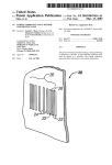
CARBON DIOXIDE TRANSMITTERS
CDT2000 Series
INSTALLATION
INSTRUCTIONS
INTRODUCTION
WARNING
Thank you for choosing an HK Instruments CDT2000 series carbon dioxide transmitter. The CDT2000 series is intended for use in
commercial environments in HVAC/R applications.
• READ THESE INSTRUCTIONS CAREFULLY BEFORE
ATTEMPTING TO INSTALL, OPERATE OR SERVICE THIS
DEVICE.
• Failure to observe safety information and comply with
instructions can result in PERSONAL INJURY, DEATH AND/OR
PROPERTY DAMAGE.
• To avoid electrical shock or damage to equipment, disconnect
power before installing or servicing and use only wiring with
insulation rated for full device operating voltage.
• To avoid potential fire and/or explosion do not use in potentially
flammable or explosive atmospheres.
• Retain these instructions for future reference.
• This product, when installed, will be part of an engineered
system whose specifications and performance characteristics
are not designed or controlled by HK Instruments. Review
applications and national and local codes to assure that the
installation will be functional and safe. Use only experienced
and knowledgeable technicians to install this device.
The CDT2000 series measures carbon dioxide (CO2), utilizing the
industry standard NDIR measurement principle, and temperature
(T). Optional relative humidity (rH) measurement is also available in
the same device. Each measurement parameter (CO2, rH, T) has a
separate field configurable output.
The CDT2000 series carbon dioxide transmitters are available with
Modbus configuration, relay and touchscreen display.
APPLICATIONS
CDT series devices are commonly used to monitor:
• CO2 and humidity levels in offices, public spaces, meeting rooms
and classrooms
• CO2 levels of return air in ventilation systems
• incoming air and return air humidity levels in ventilation system
• humidity in various industrial applications
SPECIFICATIONS
• temperatures in HVAC/R environment
SPECIFICATIONS
Performance
Physical
Electrical
Measurement ranges:
CO2: 400–2000 ppm
Temperature: 0...50 °C
Relative humidity: 0–90 %
Accuracy:
CO2: ±40 ppm + 2 % of reading
Temperature: <0.5 ºC
Relative humidity: ±4 % max @0...50 °C and 0–90 % rH
Total error band includes accuracy, hysteresis and
temperature effect over 5...50 °C and
10–90% rH.
Dimensions:
Case: 99 x 90 x 32 mm
Weight:
150 g
Mounting:
3 screw holes slotted, 3.8 mm
Materials:
Case: ABS
Protection standard:
IP20
Display (Optional)
Touchscreen
Size: 77.4 x 52.4 mm
Electrical connections:
Power supply: 5-screw terminal block
(24 V, GND, CO2, rH, T)
12–24 AWG (0.2–1.5 mm2)
Relay out: 3-screw terminal block
(NC, COM, NO)
12–24 AWG (0.2–1.5 mm2)
Input: 24 VAC or VDC, ±10 %
Current consumption 150 mA (Avg)
CO2 output signal: 0–10 V, R>1 kΩ
2–10 V, R>1 kΩ
4–20 mA, R<500 Ω
Temperature output signal: 0–10 V, R>1 kΩ
2–10 V, R>1 kΩ
4–20 mA, R<500 Ω
Relative humidity output signal: 0–10 V, R>1 kΩ
2–10 V, R>1 kΩ
4–20 mA, R<500 Ω
Relay out:
SPDT Relay, 250 V–30 V, 6 A
Technical Specifications
Media compatibility:
Dry air or non-aggressive gases
Measuring units:
ppm, °C and % rH
Measuring element:
CO2: Non-dispersive infrared (NDIR)
Temperature: Pt1000
Relative humidity: Thermoset polymer capacitive
sensing element
Environment:
Operating temperature: 0...50 °C
Storage temperature: -20...70 °C
Humidity: 0 to 95 % rH, non condensing
Copyright HK Instruments 2014
www.hkinstruments.fi
Conformance
Meets requirements for CE marking:
EMC Directive: 2004/108/EC
RoHS Directive: 2002/95/EC
WEEE Directive: 2002/96/EC
Installation version 2.0 2014
SCHEMATICS
INSTALLATION
1) Mount the device in the desired location (see step 1).
2) Route the cables and connect the wires (see step 2).
3) The device is now ready for configuration.
WARNING! Apply power only after the device is properly wired.
Display locking
jumper
Terminal block
Terminal block for relay
Contact pins for
terminal block
Jumpers
Contact pins for
relay terminal
DIMENSIONAL DRAWINGS
99.0
32.0
STEP 1: MOUNTING THE DEVICE
1) Select a mounting location on the wall at 1.2 m (4 ft) above the
floor. Locate the unit in an area with good ventilation and an
average temperature, where it will be responsive to changes
to the room conditions. The CDT may be mounted on a flat
surface.
Do not locate the CDT where it can be effected by:
• Direct sunlight
• Drafts or dead areas behind doors
• Radiant heat from appliances
• Concealed pipes or chimneys
• Outside walls or unheated / uncooled areas
90.0
2) Use the device as a template and mark the screw holes.
3) Mount the wall plate with screws.
Figure 1 - Surface mounting
83.0
45.0
14.0
49.5
Ø4
.0
Copyright HK Instruments 2014
18.0
www.hkinstruments.fi
Installation version 2.0 2014
STEP 2: WIRING DIAGRAMS
WIRING DIAGRAMS CONTINUED
CAUTION!
Figure 2b - Wiring diagram: Power input & signal output
• For CE compliance, a properly grounded shielding cable is
required.
• Use copper wire only. Insulate or wire nut all unused leads.
• Supply a separate cable for relay and signal out when using line
voltage to power the relay.
• Any wiring may carry the full operating line voltage current
based on field installation. The cover locking screw must be
installed if the line voltage is supplied to the relay.
• Care should be used to avoid electrostatic discharge to the
device.
• This unit has configuration jumpers. You may need to
reconfigure this device for your application.
+
24 V
GND
Output 0/2–10 V / 4–20 mA
CO2
Output 0/2–10 V / 4–20 mA
rH
Output 0/2–10 V / 4–20 mA
Temp
Figure 2c - Wiring diagram: Relay
NC
1) Route the cables through the square opening in the back plate
or for surface wiring select a knockout on the top or bottom of
the wall plate, as shown in Figure 2a.
2) Connect the wires as shown in Figure 2b and 2c.
COM
NO
Figure 2a - Routing the cables
STEP 3: CONFIGURATION
Configuration of the CDT series device consists of:
1) Configuring the jumpers (see step 4).
2) Configuration menu options.
(Display versions only. See the user manual for further details.)
Wires can be routed through the square opening in the back plate
No jumper
Circuit open
Jumper installed
Circuit closed
Jumper stored
(Grey colour indicates that a jumper is installed)
Wires can be routed through the top knockouts
Wires can be routed through the bottom knockouts
Copyright HK Instruments 2014
www.hkinstruments.fi
Installation version 2.0 2014
STEP 4: SELECTING THE OUTPUT MODE
WARRANTY POLICY
1) Configuration of the output modes of:
• Carbon dioxide (CO2)
• Relative humidity (rH)
• Temperature (Temp)
The seller is obligated to provide a warranty of 24 months for the delivered goods regarding material and manufacturing. The warranty
period is considered to start on the delivery date of the product. If
a defect in raw materials or a production flaw is found, the seller is
obligated, when the product is sent to the seller without delay or before expiration of the warranty, to amend the mistake at his/her discretion either by repairing the defective product or by delivering free
of charge to the buyer a new flawless product and sending it to the
buyer. Delivery costs for the repair under warranty will be paid by the
buyer and the return costs by the seller. The warranty does not comprise damages caused by accident, lightning, flood or other natural
phenomenon, normal wear and tear, improper or careless handling,
abnormal use, overloading, improper storage, incorrect care or reconstruction, or changes and installation work not done by the seller
or his/her authorized representative. The selection of materials for devices prone to corrosion is the buyer’s responsibility, unless otherwise
is legally agreed upon. Should the manufacturer alter the structure of
the device, the seller is not obligated to make comparable changes to
devices already purchased. Appealing for warranty requires that the
buyer has correctly fulfilled his/her duties arisen from the delivery and
stated in the contract. The seller will give a new warranty for goods
that have been replaced or repaired within the warranty, however only
to the expiration of the original product’s warranty time. The warranty
includes the repair of a defective part or device, or if needed, a new
part or device, but not installation or exchange costs. Under no circumstance is the seller liable for damages compensation for indirect
damage.
Select the output mode, current (4–20 mA) or voltage (0–10 V),
by installing jumpers as shown in Figure 4. Each output, CO2,
relative humidity, and temperature are configured separately.
To select 2–10 V output mode on a display version of the device:
First, select 0–10 V output by jumper(s), then change the voltage (V)
output from 0–10 V to 2–10 V via the configuration menu. Please
see the user manual for more details.
Figure 4
Jumper installed to the left side pins:
0–10 V output selected
CO2
rH
Temp
0–10 V 4–20 mA
Jumper installed to the right side pins:
4–20 mA output selected
CO2
rH
Temp
0–10 V 4–20 mA
First jumper installed to the right side pins:
4–20 mA output selected for CO2
Second and third jumper installed to the left side pins
0–10 V outputs selected for relative humidity & temperature
CO2
rH
Temp
0–10 V 4–20 mA
2) Locking the display:
Install the jumper to lock the display to prevent access to the configuration menu after installation is completed (see the schematics for the
location of the pins).
Copyright HK Instruments 2014
www.hkinstruments.fi
Installation version 2.0 2014