1
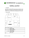
TY-ND621S
NETWORK VIDEO DECODER
USER’S MANUAL
1. Features and Benefits
The video decoder is a high resolution, Ethernet ready digital video product. Via an Ethernet network
such as LAN or WAN, the video decoder takes a H.264 stream from our IP camera or video server, and
converts it in real-time with high quality analog video signals. This allows analog video devices such as
TV system, analog monitors or existing analog video switches to be connected to our IP-base
surveillance video system.
● Up to D1 H.264 video decoding
The video decoder can convert network H.264 stream into analog video signals. It also can
automatically detect remote stream format, resolution and video standards. It can decode video at
full frame rate(30/25 fps).
● Supports both BNC and VGA video output
The video decoder has 1 BNC and 1 VGA interface. This feature allows analog video devices such as
LCD TV sets and analog monitors to be connected to our IP surveillance video system.
● Digital Time Code Embedded
The “Digital Time Code Embedded” function is to embed the recording time in the H.264 bit stream.
Therefore, each image frame has its respective time when it was recorded. It is very useful when
users want to find the video at an exact time or between a certain time intervals.
● Powerful Surveillance Software
To extend the capabilities of the video server, a powerful surveillance program is included in the
package and is totally free to use. Users can easily utilize the existing PC to be a digital video
recorder. Schedule recording, alarm recording and manual recording keep every important image
recorded in the local disk. Reliable and accurate motion detection with instant warning makes you
responsive in every condition. Quick and simple search and playback function lets you easily find
the images you want.
2. Parameters
Technical Specification
TY-ND621S Network Video Decoder
Video Interface
1 BNC and 1 VGA video output
Audio Interface
RCA Interface: 1 Channel Audio Input, 1 Channel Audio Output
Video Compression Mode
H.264
Audio Compression Mode
G.726
Image Resolution
720×576 (1 picture) / 352×288(4 pictures)
Frame Rate
25 fps / 30 fps
Network Interface
10BaseT/100BaseTX Ethernet Interface
Network Protocol
TCP/UDP/HTTP/MULTICAST
IP Address
Support Static IP Address and Dynamic IP Analysis
Transmission Bandwidth
64k~3M bps
Alarm Output
1 Channel Alarm Output (Contact Closure)
Clock
Embedded Clock
Control Interface
RS-485 Interface: 1 Channel 485 PTZ Control
System Upgrade
Support Remote Upgrade
Operating Temperature
0℃~50℃
Operating Humidity
20~80% RHG
Output Voltage
DC 12V / 3A
Power
Less than 5Watt
Dimension
180mm×122mm×44mm
3. Safety Instructions
● Don’t use the power supply with other voltages
● Don’t open the housing of the product
● Cleaning
Disconnect this video product from the power supply before cleaning.
● Attachments
Do not use attachments not recommended by the video product manufacturer as they may cause
hazards.
● Water and Moisture
Do not use this video product near water, for example, near a bahtub, washbowl, kitchen sink, or
laundry tub, in a wet basement, or near a swimming pool and the like.
● Only install this device and the power supply in a dry place protected from weather.
4. Physical Description
① Power Input: DC 12V&3A Input: When the power supply is normal, the red light on.
② COM: Alarm Output GND
NO: Alarm Output
③ A: PTZ Control 485 Signal A
B: PTZ Control 485 Signal B
G: PTZ Control 485 Signal GND
④ AUD IN: Audio Input
⑤ AUD OUT: Audio Output
⑥ VIDEO OUTPUT: Video output, BNC
⑦ VGA: Video output, VGA
⑧ RJ-45:10/100BASE-T, self-adapted
⑨ RST: Reset button. Using a suitable pointed object, press and continue to hold the reset button
depressed for 3 seconds when the power on.
5. Basic Connections
Follow the procedures below to connect the video decoder to the respective apparatuses.
1. The IP camera or other encoding devices as a video source.
2. The video server or other encoding devices as a video source.
3. Connect video server / IP camera and video decoder to and Ethernet hub
4. Video Decoder is the receiver side.
5. Connect a coaxial cable to TV monitor and display the video which encoded and transferred from
video server / IP camera.
Note: software installation and operation please refers to software user manual.