Download Quick Start Guide
Transcript
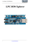
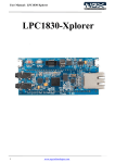
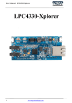
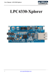
Quick Start Guide: LPC4330-Xplorer LPC1830-Xplorer User Manuals for Xplorer: For KEIL MDK-ARM with ULINK2/ME: Click here For LPC-Xpresso with NXP-LPCLink: Click here Sample projects for Xplorer: For KEIL MDK-ARM: Click here For LPC-Xpresso: Click here Schematic for Xplorer Board: Click here to download Schematic. USB Virtual Com INF file: Click here to download USB Virtual Com INF file. 1 www.ngxtechnologies.com Quick Start Guide: LPC1830-Xplorer About NGX Technologies NGX Technologies is a premier supplier of development tools for the ARM7, ARM Cortex M0, M3 and M4 series of microcontrollers. NGX provides innovative and cost effective design solutions for embedded systems. We specialize in ARM MCU portfolio, which includes ARM7, Cortex-M0, M3 & M4 microcontrollers. Our experience with developing evaluation platforms for NXP controller enables us to provide solutions with shortened development time thereby ensuring reduced time to market and lower development costs for our customers. Our cost effective and feature rich development tool offering, serves as a testimony for our expertise, cost effectiveness and quality. Contact Information: NGX Technologies Pvt. Ltd. No.216, 5th main Road, R.P.C. Layout, Vijayanagar 2nd Stage, Bangalore – 560 104 Phone : +91-80-40925507 email:[email protected] CE certification: NGX Technologies LPC1830-Xplorer board has been tested for radiated emission as per EN55022 class a standard. The device is under the limits of the standard EN55022 class A and hence CE marked. No other test have been conducted other than the radiated emission (EN55022 class A standard). The device was tested with the ports like USB, Serial, and Power excluding the GPIO ports. Any external connection made to the GPIO ports may alter the EMC behavior. Usage of this device under domestic environment may cause unwanted interference with other electronic equipment’s. User is expected to take adequate measures. The device is not intended to be used in and end product or any subsystem unless the user re-evaluates applicable directive/conformance. 2 www.ngxtechnologies.com Quick Start Guide: LPC1830-Xplorer Table of Contents 1.0 INTRODUCTION ................................................................................................................................. 4 1.1 LPC1830 Xplorer Ordering Options ................................................................................................. 4 1.2 ARM JTAG (20-pin) to Cortex JTAG (10-pin) Adaptor .................................................................. 6 1.3 ULINK-ME and KEIL ...................................................................................................................... 7 1.4 ULINK2 and KEIL ............................................................................................................................ 7 1.5 NXP-LPCLink and LPCXpresso....................................................................................................... 8 2.0 LPC1830-Xplorer Overview ................................................................................................................. 8 2.1 Introduction ....................................................................................................................................... 8 2.2 Board Features ................................................................................................................................... 9 2.3 BLOCK DIAGRAM ......................................................................................................................... 9 2.4 LPC1830-Xplorer pin out ................................................................................................................ 10 2.5 LPC1830 description ....................................................................................................................... 10 3.0 LPC1830-Xplorer verification ............................................................................................................ 12 3.1 Board Image with pointers to the peripherals ................................................................................. 12 3.2 Powering the Board ......................................................................................................................... 13 3.3 Verifying all the peripherals on LPC1830-Xplorer ......................................................................... 13 3.3.1 LEDs ............................................................................................................................................. 19 3.3.2 USB1 (Virtual COM port) ............................................................................................................ 19 3.3.3 User Input Switch ......................................................................................................................... 22 3.3.4 USB0 (HID device) ...................................................................................................................... 22 3.3.5 Ethernet ........................................................................................................................................ 23 3.3.6 Micro SD connector ..................................................................................................................... 25 3.3.7 Audio Interface ............................................................................................................................. 25 3 www.ngxtechnologies.com Quick Start Guide: LPC1830-Xplorer 1.0 INTRODUCTION This document is a ‘Quick Start Guide’ for LPC1830-Xplorer; a cost effective evaluation platform for NXP’s LPC18xx MCU. This document focuses on the kit contents, board verification, possible debuggers and IDEs that can be used. 1.1 LPC1830 Xplorer Ordering Options Option A: With ULINK-ME debugger This option is recommended for customers that do not already have a suitable debug probe. The Xplorer is packaged as shown in the image below. TBD Fig. 1 4 www.ngxtechnologies.com Quick Start Guide: LPC1830-Xplorer After unboxing the package you should find Xplorer Board, ULINK-ME, 2 ‘USB AM to Micro B’ cable and ‘USB AF to Micro B’ cable as shown in the following image. Fig. 2 Option B: Without the debugger This option is recommended for customers who already own and wish to use a debugger such as. ULINK2 with KEIL uVision NXP LPCLink with LPCXpresso Red Probe+ with Red Suite from Code Red I-jet with IAR Embedded Workbench Segger JLink with IAR Embedded Workbench or KEIL uVision The Xplorer is packaged as shown in the following image. Fig. 3 5 www.ngxtechnologies.com Quick Start Guide: LPC1830-Xplorer After unboxing the package you should find Xplorer Board, ‘USB AM to Micro B’ cable and ‘USB AF to Micro B’ cable as shown in the following image. Fig. 4 1.2 ARM JTAG (20-pin) to Cortex JTAG (10-pin) Adaptor Please note that your existing debugger might be supporting only the ‘20-pin ARM JTAG connector’. In such scenarios one would require a ‘20-pin to 10-pin adaptor’ and the necessary cables. The Xplorer has on board ‘Cortex SWD/JTAG 10-pin male connector’, the ‘20-pin to 10-pin adaptor’ is not a part of the Xplorer package and user needs to buy them separately. If the debugger supports the ‘10-pin Cortex header’ one needs to have the 10-pin ribbon cable and can directly connect to the Xplorer. Please note even the 10-pin ribbon cable is not a part of standard delivery and needs to be procured separately. The picture below shows 20-pin ribbon cable, 10-pin ribbon cable and ‘20-pin to 10-pin adaptor’. Fig. 5 6 www.ngxtechnologies.com Quick Start Guide: LPC1830-Xplorer 1.3 ULINK-ME and KEIL Connect one end of 10-pin ribbon cable ‘ULINK-ME 10-pin box header’ and other end to Xplorer as shown in the below image. The hardware setup is now ready for programing an Xplorer board with ULINK-ME and KEIL IDE. Please refer keil knowledgebase article for connecting ‘ULINK-ME 10-pin ribbon cable’ to NGX Xplorer. Fig. 6 1.4 ULINK2 and KEIL Connect ‘ULINK2 20-pin cable’ to ‘20-pin to 10-pin adaptor’ and connect one end of 10-pin ribbon cable to ‘20-pin to 10-pin adaptor’ and other end to Xplorer as shown in the below image. The hardware setup is now ready for programing an Xplorer board with ULINK2 and KEIL IDE. Please refer keil knowledgebase article for connecting ULINK2 to NGX Xplorer. Fig. 7 7 www.ngxtechnologies.com Quick Start Guide: LPC1830-Xplorer 1.5 NXP-LPCLink and LPCXpresso Separate the LPCXpresso controller part and use only the NXP LPCLink as shown in the following image. Fig. 8 The Xplorer board has on board ‘Cortex SWD/JTAG 10-pin box header’; connect one end of the 10-pin ribbon cable to NXP LPCLink and other end to Xplorer. Make sure the 10-pin ribbon cable notch on the connector is facing towards the arrow mark on the NXP LPCLink. The hardware setup is now ready for programing an Xplorer board with NXP LPCLink and LPCXpresso. 2.0 LPC1830-Xplorer Overview 2.1 Introduction The NGX LPC1830-Xplorer is a compact and versatile evaluation platform for the NXP's Cortex-M3 based MCUS. NGX's evaluation platforms are generally not tied up to any particular debugger or compiler/IDE. However it is not practical to test and ensure that the solution would work out of box with all the available debuggers and compilers/IDE. As long as the compiler supports the particular MCU and the debugger supports the standard debug interfaces like the SWD/JTAG you can use this platform with any tool. The board is supported by extensive sample examples allowing you to focus on the application development. 8 www.ngxtechnologies.com Quick Start Guide: LPC1830-Xplorer 2.2 Board Features Following are the salient features of the board Dimensions: 86mm X 40mm Controller: LPC1830, 100 pin BGA PCB: 4-layer (RoHS complaint) Two LEDs One user switch and one reset switch Boot select switch 32Mb Quad flash On board crystals for controller, RTC and audio codec On board Ethernet PHY, 50 MHz Oscillator and RJ45 connector with magnetics On board audio codec and audio jacks On board USB host power switch Two USB ports, one HS (High speed) port and one FS (Full Speed) port 10-pin cortex debug header The board is shipped with two USB cables, one USB device cable and one USB host adapter cable Unused I/Os brought to a header (pin compatible with Xpresso pinning*) *The I/0s brought out to the header are not 100% pin compatible with Xpresso Pinning, unlike the Xpresso boards, this evaluation platform has lot of connectors on board. We have put in our best efforts to have maximum number of pins to be Xpresso pin compatible. 2.3 BLOCK DIAGRAM Fig. 9 9 www.ngxtechnologies.com Quick Start Guide: LPC1830-Xplorer 2.4 LPC1830-Xplorer pin out Fig.10 2.5 LPC1830 description The LPC1830 is a high-performance, cost-effective Cortex-M3 microcontroller featuring 200 kB of SRAM, and advanced peripherals including Ethernet, High Speed USB 2.0 Host/OTG/Device and CAN 2.0B. Operating at speeds up to 180 MHz, the LPC1830 also features two new configurable peripherals: a SPI Flash Interface and a State Configurable Timer. All members of the series include a Wakeup Interrupt Controller allowing automatic wake from any priority interrupt as well as four reduced power modes: Sleep, Deep-Sleep, Power-Down, and Deep Power-Down. 10 ARM Cortex-M3 processor, running at frequencies of up to 180 MHz ARM Cortex-M3 built-in Memory Protection Unit (MPU) supporting eight regions ARM Cortex-M3 built-in Nested Vectored Interrupt Controller (NVIC) Non-maskable Interrupt (NMI) input JTAG and Serial Wire Debug ETM and ETB support System tick timer 200 kB SRAM for code and data use 32 kB ROM containing boot code and on-chip software drivers Crystal oscillator with an operating range of 1 MHz to 25 MHz 12 MHz internal RC oscillator trimmed to 1 % accuracy Ultra-low power RTC crystal oscillator www.ngxtechnologies.com Quick Start Guide: LPC1830-Xplorer Clock output Two PLLs allow CPU operation up to the maximum CPU rate Quad SPI Flash Interface with four lanes and data rates of up to 40 MB/s 10/100T Ethernet MAC with RMII and MII interfaces and DMA support One High-speed USB 2.0 Host/Device/OTG interface with DMA support One High-speed USB 2.0 Host/Device interface with DMA support Four 550 UARTs with DMA support: one UART with full modem interface One UART with IrDA interface One C_CAN 2.0B controller with one channel Two SSP controllers with FIFO and multi-protocol support One Fast-mode Plus I2C-bus interface with monitor mode One standard I2C-bus interface with monitor mode and standard I/O pins One I2S interface with DMA support and with one input and one output External Memory Controller (EMC) SD/MMC card interface Eight-channel General-Purpose DMA (GPDMA) controller Up to 49 General-Purpose Input/Output (GPIO) pins GPIO registers are located on the AHB for fast access State Configurable Timer (SCT) subsystem on AHB Four general-purpose timer/counters with capture and match capabilities One motor control PWM for three-phase motor control One Quadrature Encoder Interface (QEI) Repetitive Interrupt timer (RI timer) Windowed watchdog timer Ultra-low power Real-Time Clock (RTC) on separate power domain Alarm timer; can be battery powered One 10-bit DAC with DMA support and a data conversion rate of 400 kSamples/s Two 10-bit ADCs with DMA support and a data conversion rate of 400 kSamples/s Hardware-based AES security engine programmable through an on-chip API Two 128-bit secure OTP memories for AES key storage and customer use Unique ID for each device Single 3.3 V (2.2 V to 3.6 V) power supply with on-chip voltage regulator RTC power domain can be powered separately by a 3 V battery supply Four reduced power modes Overdrive mode to increase CPU and bus clock frequency Processor wake-up from Sleep mode via wake-up interrupts Wake-up from Deep-sleep, Power-down, and Deep power-down modes Brownout detect with four separate thresholds for interrupt and forced reset Power-On Reset (POR) For the most updated information on the MCU please refer to NXP's website. 11 www.ngxtechnologies.com Quick Start Guide: LPC1830-Xplorer 3.0 LPC1830-Xplorer verification NGX's evaluation platforms ship with a factory-programmed test firmware that verifies all the on-board peripherals. It is highly recommended that you verify the board, before you start programming. Also this exercise helps you get acclimatized with the board quickly. To run the tests you will need the following: LPC1830-Xplorer Power: USB cable (you can power it through either port, we recommend to use USB1 for the verification) or external power supply (Alternatively the Xplorer has a 5V in pin available for powering through external power source) PC: With Windows7 or XP (32-bit) One USB AM to Micro B cable in addition to the one provided with the KIT Micro SD card 2-GB USB pen drive Audio-in (Auxiliary) cable (3.5mm diameter connector) 3.1 Board Image with pointers to the peripherals Fig.11 12 www.ngxtechnologies.com Quick Start Guide: LPC1830-Xplorer 3.2 Powering the Board The LPC1830-Xplorer can be powered through USB; we can either power it from USB0 port or USB1 port. It is highly recommended that the user tests all the peripherals as soon as the board is received. A regulated supply can be supplied to the 5V pin on the Xplorer-LPC1830 header. Note: The USB power can source only up to 500 mA of current. For applications having higher current requirements we recommend to use an external power supply. Please note that the external power supply is not a part of standard delivery. 3.3 Verifying all the peripherals on LPC1830-Xplorer The following section focuses on the verification of all the peripherals supported on the LPC1830Xplorer. The order of the tests is mentioned in the same manner as the flow of the test firmware. We highly recommend that you follow the order of the test. The test firmware is designed in a manner that the user needs to spend as minimum time as possible to verify all the on-board peripherals. The test firmware executable resides on the Quad Flash. The BOOT select switch is configured to execute from the Quad Flash interface. Note: The test firmware “Debug Messages” or flow might be changed in due course. Generally these are only cosmetic changes so that the usage is easier. If you observe a different message than the one mentioned in the Manual, do not worry and please proceed with the test. Important Note: The user needs to press the RESET switch twice to be able to reset the controller. This is due to the issue with the silicon. However for the power up reset (USB power cycle) the controller boots up fine. Power up the board over USB1 port and we are all set to verify the LPC1830-Xplorer peripherals. Before we get to the verification we need to install the Virtual COM port drivers needed for the LPC1830-Xplorer (USB1 port) to appear as a Virtual COM port (Used for viewing the debug messages on serial emulation tool). Fortunately, this is a one-time setup and fairly simple. On a Windows machine the user needs to point to the location of the INF file. Download INF file Click Here 13 www.ngxtechnologies.com Quick Start Guide: LPC1830-Xplorer Steps to install the VCOM drivers on windows 7 machine: Step 1: Connect USB1 to the computer, Open device manager, you can find “NXP LPC18xx VCOM” new device listed under ‘Other devices’. Fig.12 Step 2: Right click on the “NXP LPC18xx VCOM” and then left click on ‘Update Driver Software’. Fig.13 14 www.ngxtechnologies.com Quick Start Guide: LPC1830-Xplorer Step 3: Click on Browse my computer for driver software. Fig.14 Step 4: Click Browse, select downloaded LPC1830_Xplorer_VCOM_inf unzipped driver folder and then click on OK. Fig.15 15 www.ngxtechnologies.com Quick Start Guide: LPC1830-Xplorer Step 5: Click on Next to continue driver installation. Fig.16 Step 6: Click on ‘Install this driver software anyway’. Fig.17 16 www.ngxtechnologies.com Quick Start Guide: LPC1830-Xplorer Step 7: The ‘LPC18xx USB VCom driver’ is successfully installed, click on close. Fig.18 Step 8: Now ‘LPC18xx USB VCom Port’ (COM12) is ready to use. Fig.19 Note: The Virtual COM is listed under the device manager. Please note that the COM port list under the Device Manager is automatically updated with the COM port number for the Virtual COM. On our test machine we see two COM ports listed COM1 and COM12. COM1 is the actual COM port and COM12 is the virtual COM port. The COM12 will appear only if the Xplorer board is connected (USB1) to the PC. Every time the Xplorer is reset the user needs to close the Hyper Terminal application and restart it again. 17 www.ngxtechnologies.com Quick Start Guide: LPC1830-Xplorer The orders in which the on-board peripherals are verified by the firmware are as follows: Test Firmware Flowchart: A START Is VCOM Enumeration Completed? Ethernet PHY Verification NO Audio codec Verification YES Wait for user input flag == 1? B NO YES Xplorer peripheral initialization USB0 HID Enumeration B SD card Verification LED Blink (D2 and D3) A 18 www.ngxtechnologies.com Quick Start Guide: LPC1830-Xplorer 3.3.1 LEDs Test setup and verification: As soon as the Xplorer is turned ON or reset; the test LEDs go ON & OFF for a couple of times, this simple test validates the LEDs. The Xplorer has one Green LED and one Blue LED. These LEDs are also connected to the outputs of the SCT lines. Please refer to the schematics for more details. 3.3.2 USB1 (Virtual COM port) Test setup and verification: For the very first time the windows machine will ask for the appropriate virtual COM drivers to be installed. Steps to select ‘USB1 VCOM port’ on HyperTerminal in windows 7 machine: Step 1: Open a HyperTerminal, type name and click on OK. Fig.20 19 www.ngxtechnologies.com Quick Start Guide: LPC1830-Xplorer Step 2: Select ‘USB1 Vcom Port’ (COM12) and click on OK. Fig.21 Step 3: Click on ‘Restore Defaults’ and click on OK. Fig.22 20 www.ngxtechnologies.com Quick Start Guide: LPC1830-Xplorer Step 4: Now the ‘USB1 VCom’ is ready to use. Fig.23 Note: You would not be able to proceed with the verification unless the Virtual COM drivers are installed. The firmware waits for the USB1 to enumerate as VCOM port. 21 www.ngxtechnologies.com Quick Start Guide: LPC1830-Xplorer 3.3.3 User Input Switch Test setup and verification: Once the VCOM drivers are installed the Xplorer waits for the User Input Switch to be pressed. Only after detecting a user button (SW2) press the test firmware proceeds with validating other peripherals. This synchronization is necessary to ensure that the debug messages on the VCOM port can be viewed from the start of the test. Without this synchronization the test firmware would proceed with the debug messages being displayed, while the user is still configuring the Hyper-Terminal or other serial emulation tool. Fig.24 3.3.4 USB0 (HID device) Test setup and verification: Connect the USB cable to USB0 connector. The USB enumeration can be checked in device manager. The Xplorer enumerates as a Human Interface Device (HID). On a Windows machine this can be confirmed by looking in to the ‘Device Manager’ under ‘Human Interface Devices’. 22 www.ngxtechnologies.com Quick Start Guide: LPC1830-Xplorer Fig.25 Note: The Xplorer is shipped with only one ‘USB AM to micro B’; to test the USB1 interface you would require another similar cable. In the subsequent firmware releases the firmware would configure the USB0 port as USB host. 3.3.5 Ethernet Test setup and verification: The test firmware configures the Xplorer board as a webserver. Fig.26 23 www.ngxtechnologies.com Quick Start Guide: LPC1830-Xplorer The ethernet interface can be verified by either using a PING command in the windows command prompt. Fig.27 The IP address of the Xplorer board is configured as 192.168.1.123. Type the same IP address in the browser. Clicking the ON button will TURN-ON LED D3 and clicking OFF button will TURN-OFF LED D3. Fig.28 24 www.ngxtechnologies.com Quick Start Guide: LPC1830-Xplorer 3.3.6 Micro SD connector Test setup and verification: The firmware validates the micro SD card interface by writing and reading a sector of the SD card connected. Please note that we need to use a micro SD card with FAT file system. The result of this test is displayed over the VCOM port. Fig.29 3.3.7 Audio Interface Test setup and verification: For the audio interface the LPC1830 Xplorer incorporates external audio codec from NXP. The codec is interfaced to the MCU over I2S0 for data and over I2C0 for command interface. The test firmware verifies both the audio-in and audio-out path. To verify the audio interface the user needs to feed some audio data through the audio-in (LINE-IN) interface and then connect a headphone at the audio-out jack. If one is able to hear the same audio data that is being fed over audio-in interface, we have verified the audio interface. Fig.30 25 www.ngxtechnologies.com Quick Start Guide: LPC1830-Xplorer About this document: Revision History Version: V1 author: Nagaraj Baddi Company Terms & Conditions Legal NGX Technologies Pvt. Ltd. provides the enclosed product(s) under the following conditions: This evaluation board/kit is intended for use for ENGINEERING DEVELOPMENT, DEMONSTRATION, and EDUCATION OR EVALUATION PURPOSES ONLY and is not considered by NGX Technologies Pvt. Ltd to be a finished end-product fit for general consumer use. Persons handling the product(s) must have electronics training and observe good engineering practice standards. As such, the goods being provided are not intended to be complete in terms of required design-, marketing-, and/or manufacturing-related protective considerations, including product safety and environmental measures typically found in end products that incorporate such semiconductor components or circuit boards. This evaluation board/kit does not fall within the scope of the European Union directives regarding electromagnetic compatibility, restricted substances (RoHS), recycling (WEEE), FCC, CE or UL and therefore may not meet the technical requirements of these directives or other related directives. The user assumes all responsibility and liability for proper and safe handling of the goods. Further, the user indemnifies NGX Technologies from all claims arising from the handling or use of the goods. Due to the open construction of the product, it is the user’s responsibility to take any and all appropriate precautions with regard to electrostatic discharge. EXCEPT TO THE EXTENT OF THE INDEMNITY SET FORTH ABOVE, NEITHER PARTY SHALL BE LIABLE TO THE OTHER FOR ANY INDIRECT, SPECIAL, INCIDENTAL, OR CONSEQUENTIAL DAMAGES. NGX Technologies currently deals with a variety of customers for products, and therefore our arrangement with the user is not exclusive. NGX Technologies assumes no liability for applications assistance, customer product design, software performance, or infringement of patents or services described herein. Please read the User’s Guide and, specifically, the Warnings and Restrictions notice in the User’s Guide prior to handling the product. This notice contains important safety information about temperatures and voltages. No license is granted under any patent right or other intellectual property right of NGX Technologies covering or relating to any machine, process, or combination in which such NGX Technologies products or services might be or are used. 26 www.ngxtechnologies.com Quick Start Guide: LPC1830-Xplorer Disclaimers Information in this document is believed to be reliable and accurate. However, NGX Technologies does not give any representations or warranties, expressed or implied, as to the completeness or accuracy of such information and shall have no liability for the consequences of use of such information. NGX Technologies reserves the right to make changes to information published in this document, at any time and without notice, including without limitation specifications and product descriptions. This document replaces and supersedes all information supplied prior to the publication hereof. Trademarks All referenced trademarks, product names, brands and service names are the property of their respective owners. 27 www.ngxtechnologies.com