1
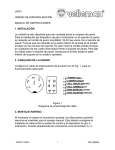
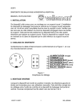
VISP1
PAN/TILT UNIT
USER MANUAL
1. INSTALLATION
The unit is intended to be mounted on a Wall Mount. Installation of the pan
and tilt drive to the wall mount requires a stainless steel 1/4-20 screw
supplied with the wall mount. Note the ribs on the underside of the unit base
engage slots in the mount. This allows positioning of the unit in any of four
directions with respect to the wall mount. Secure unit to the wall mount using
screw from underside of wall mount into unit and tighten.
2. WIRING OF UNIT
Fabricate the interconnecting cable in accordance with Figure 1. for proper
operation.
POWER (red)
COMMON (black)
TILT DOWN (yellow)
TILT UP (blue)
PAN RIGHT (green)
PAN LEFT (white)
Figure 1
Cable Assembly Diagram
3. INVERTED MOUNTING
When the unit is mounted in the inverted position, the left-right directions are
reversed for manual operation. This must be corrected when wiring the cable
between control unit and the pan and tilt drive. Simply reverse leads going to
terminals 3 and 4.
4. ADJUSTING LIMIT STOPS
After cable is installed and unit has been mounted, proceed as follow :
1. Plug control unit into AC 24V source. Be sure auto switch is in the OFF
position.
VSCP1-VISP1
1
VELLEMAN
2.
3.
To adjust pan limit stops (see Figure 2), loosen screws securing both
stops (1) and (3) to unit. Slide stops around unit to desired locations and
secure by tightening screws.
To adjust tilt limit stops (see Figure 2) located in each end plate, remove
two screws securing each end cap to unit. Loosen and adjust tilt limit
stop screws for desired tilt limit position. Tighten limit stop screws and
reinstall each end caps to unit and secure with two screws.
Figure 2
Limit Stop Adjustment and Camera Mounting Plate
VSCP1-VISP1
2
VELLEMAN
1.
2.
3.
4.
5.
6.
7.
8.
9.
10.
Right Pan Limit Stop
Limit-Switch Actuator
Left Pan Limit Stop
Tilt Limit Stop Screw
Camera Mounting Plate
Screw
Down Limit Stop
4-conductor cable for video signal
Connection to control (VSCP1)
Video Output
5. MAINTENANCE
This pan and tilt drive requires no lubrication or maintenance for the life of the
unit. If the unit fails to function, turn it off and check the fuse on the control
unit. Replacement fuse values are given in the instructions supplied with the
control unit.
6. SPECIFICATIONS
Angular travel :
Limited Stop :
Speed :
Load Rating :
Duty Cycle :
Input Voltage :
Power Consumption :
Normal Operating Current :
Cable Requirement :
Operating Temperature :
Construction :
Finish :
Dimensions :
Weight :
VSCP1-VISP1
Pan : 350° / Tilt : ± 75°
Externally adjustable
Pan : 6° / second
Tilt : 4° / second
Pan : 7 kg / Tilt : 5 kg
Pan : continuous
Tilt : intermittent
AC 24V
6W
24V-200mA
Six-conductor, unshielded
-5°C to + 60°C
Aluminium and plastic
Off white baked enamel finish
150 x 160 x 200mm
2.3 kg
3
VELLEMAN
VSCP1
PAN/TILT SCANNER CONTROL
USER MANUAL
Feature :
► Auto on : LED - Green
► Bypass on : LED - Red
► Non light during off
► Special screw terminal-detachable connector easy for installation
Specifications :
Tilt control :
Pan control :
Power control :
Input Voltage :
Output Voltage to Scanner :
Temperature Operating :
Connector :
Construction :
Dimensions :
Weight :
VSCP1-VISP1
Push Button, UP/DOWN
Push Button, LEFT/RIGHT
Slide Switch MAN/OFF/AUTO
AC 220-230V
AC 24V
-10°C to +60°C
Screw Terminal-Detachable
Steel, Off-White Textured
212 x 218 x 45mm
1.2Kg
4
VELLEMAN
Operations :
FRONT PANEL 1. Power :
Push the rocker switch to "AUTO", the Green LED
will illuminate.
Scanner automatic left and right adjust.
Push the rocker switch to "MAN", the Red LED
will illuminate.
Scanner adjust by manual.
2.
3.
UP AND DOWN :
LEFT AND RIGHT :
BACK PANEL 1. AC POWER :
2. LEFT :
3. RIGHT :
4. COM :
5. UP :
6. DOWN :
VSCP1-VISP1
Non light during "OFF"
Paddle switch, UP/DOWN
Paddle switch, LEFT/RIGHT
Terminal block no. 1 point
Terminal block no. 2 point
Terminal block no. 3 point
Terminal block no. 4 point
Terminal block no. 5 point
Terminal block no. 6 point
5
VELLEMAN